EP3317088B1 - Unité d'entraînement hydroélectrique - Google Patents
Unité d'entraînement hydroélectrique Download PDFInfo
- Publication number
- EP3317088B1 EP3317088B1 EP16795020.3A EP16795020A EP3317088B1 EP 3317088 B1 EP3317088 B1 EP 3317088B1 EP 16795020 A EP16795020 A EP 16795020A EP 3317088 B1 EP3317088 B1 EP 3317088B1
- Authority
- EP
- European Patent Office
- Prior art keywords
- drive unit
- unit according
- hydraulic
- cylinder
- flange
- Prior art date
- Legal status (The legal status is an assumption and is not a legal conclusion. Google has not performed a legal analysis and makes no representation as to the accuracy of the status listed.)
- Active
Links
- 239000012530 fluid Substances 0.000 claims description 21
- 238000005086 pumping Methods 0.000 claims description 10
- 230000002441 reversible effect Effects 0.000 claims description 3
- 238000001816 cooling Methods 0.000 description 5
- 238000010586 diagram Methods 0.000 description 5
- 230000008901 benefit Effects 0.000 description 4
- 230000006837 decompression Effects 0.000 description 4
- 238000013461 design Methods 0.000 description 4
- 238000011161 development Methods 0.000 description 4
- 238000003825 pressing Methods 0.000 description 4
- 238000004891 communication Methods 0.000 description 2
- 230000001419 dependent effect Effects 0.000 description 2
- 238000001914 filtration Methods 0.000 description 2
- 238000009434 installation Methods 0.000 description 2
- 238000012986 modification Methods 0.000 description 2
- 230000004048 modification Effects 0.000 description 2
- 230000008859 change Effects 0.000 description 1
- 238000006073 displacement reaction Methods 0.000 description 1
- 230000002349 favourable effect Effects 0.000 description 1
- 238000012423 maintenance Methods 0.000 description 1
- 238000004519 manufacturing process Methods 0.000 description 1
- 238000000034 method Methods 0.000 description 1
- 238000012544 monitoring process Methods 0.000 description 1
- 230000008569 process Effects 0.000 description 1
- 230000009467 reduction Effects 0.000 description 1
- 238000009423 ventilation Methods 0.000 description 1
Images


Classifications
-
- B—PERFORMING OPERATIONS; TRANSPORTING
- B30—PRESSES
- B30B—PRESSES IN GENERAL
- B30B15/00—Details of, or accessories for, presses; Auxiliary measures in connection with pressing
- B30B15/16—Control arrangements for fluid-driven presses
- B30B15/18—Control arrangements for fluid-driven presses controlling the reciprocating motion of the ram
- B30B15/20—Control arrangements for fluid-driven presses controlling the reciprocating motion of the ram controlling the speed of the ram, e.g. the speed of the approach, pressing or return strokes
-
- B—PERFORMING OPERATIONS; TRANSPORTING
- B30—PRESSES
- B30B—PRESSES IN GENERAL
- B30B15/00—Details of, or accessories for, presses; Auxiliary measures in connection with pressing
- B30B15/16—Control arrangements for fluid-driven presses
-
- F—MECHANICAL ENGINEERING; LIGHTING; HEATING; WEAPONS; BLASTING
- F15—FLUID-PRESSURE ACTUATORS; HYDRAULICS OR PNEUMATICS IN GENERAL
- F15B—SYSTEMS ACTING BY MEANS OF FLUIDS IN GENERAL; FLUID-PRESSURE ACTUATORS, e.g. SERVOMOTORS; DETAILS OF FLUID-PRESSURE SYSTEMS, NOT OTHERWISE PROVIDED FOR
- F15B11/00—Servomotor systems without provision for follow-up action; Circuits therefor
- F15B11/02—Systems essentially incorporating special features for controlling the speed or actuating force of an output member
- F15B11/022—Systems essentially incorporating special features for controlling the speed or actuating force of an output member in which a rapid approach stroke is followed by a slower, high-force working stroke
-
- F—MECHANICAL ENGINEERING; LIGHTING; HEATING; WEAPONS; BLASTING
- F15—FLUID-PRESSURE ACTUATORS; HYDRAULICS OR PNEUMATICS IN GENERAL
- F15B—SYSTEMS ACTING BY MEANS OF FLUIDS IN GENERAL; FLUID-PRESSURE ACTUATORS, e.g. SERVOMOTORS; DETAILS OF FLUID-PRESSURE SYSTEMS, NOT OTHERWISE PROVIDED FOR
- F15B15/00—Fluid-actuated devices for displacing a member from one position to another; Gearing associated therewith
- F15B15/18—Combined units comprising both motor and pump
-
- F—MECHANICAL ENGINEERING; LIGHTING; HEATING; WEAPONS; BLASTING
- F15—FLUID-PRESSURE ACTUATORS; HYDRAULICS OR PNEUMATICS IN GENERAL
- F15B—SYSTEMS ACTING BY MEANS OF FLUIDS IN GENERAL; FLUID-PRESSURE ACTUATORS, e.g. SERVOMOTORS; DETAILS OF FLUID-PRESSURE SYSTEMS, NOT OTHERWISE PROVIDED FOR
- F15B1/00—Installations or systems with accumulators; Supply reservoir or sump assemblies
- F15B1/26—Supply reservoir or sump assemblies
-
- F—MECHANICAL ENGINEERING; LIGHTING; HEATING; WEAPONS; BLASTING
- F15—FLUID-PRESSURE ACTUATORS; HYDRAULICS OR PNEUMATICS IN GENERAL
- F15B—SYSTEMS ACTING BY MEANS OF FLUIDS IN GENERAL; FLUID-PRESSURE ACTUATORS, e.g. SERVOMOTORS; DETAILS OF FLUID-PRESSURE SYSTEMS, NOT OTHERWISE PROVIDED FOR
- F15B2211/00—Circuits for servomotor systems
- F15B2211/20—Fluid pressure source, e.g. accumulator or variable axial piston pump
- F15B2211/205—Systems with pumps
- F15B2211/20507—Type of prime mover
- F15B2211/20515—Electric motor
-
- F—MECHANICAL ENGINEERING; LIGHTING; HEATING; WEAPONS; BLASTING
- F15—FLUID-PRESSURE ACTUATORS; HYDRAULICS OR PNEUMATICS IN GENERAL
- F15B—SYSTEMS ACTING BY MEANS OF FLUIDS IN GENERAL; FLUID-PRESSURE ACTUATORS, e.g. SERVOMOTORS; DETAILS OF FLUID-PRESSURE SYSTEMS, NOT OTHERWISE PROVIDED FOR
- F15B2211/00—Circuits for servomotor systems
- F15B2211/20—Fluid pressure source, e.g. accumulator or variable axial piston pump
- F15B2211/205—Systems with pumps
- F15B2211/2053—Type of pump
- F15B2211/20538—Type of pump constant capacity
-
- F—MECHANICAL ENGINEERING; LIGHTING; HEATING; WEAPONS; BLASTING
- F15—FLUID-PRESSURE ACTUATORS; HYDRAULICS OR PNEUMATICS IN GENERAL
- F15B—SYSTEMS ACTING BY MEANS OF FLUIDS IN GENERAL; FLUID-PRESSURE ACTUATORS, e.g. SERVOMOTORS; DETAILS OF FLUID-PRESSURE SYSTEMS, NOT OTHERWISE PROVIDED FOR
- F15B2211/00—Circuits for servomotor systems
- F15B2211/20—Fluid pressure source, e.g. accumulator or variable axial piston pump
- F15B2211/205—Systems with pumps
- F15B2211/2053—Type of pump
- F15B2211/20561—Type of pump reversible
-
- F—MECHANICAL ENGINEERING; LIGHTING; HEATING; WEAPONS; BLASTING
- F15—FLUID-PRESSURE ACTUATORS; HYDRAULICS OR PNEUMATICS IN GENERAL
- F15B—SYSTEMS ACTING BY MEANS OF FLUIDS IN GENERAL; FLUID-PRESSURE ACTUATORS, e.g. SERVOMOTORS; DETAILS OF FLUID-PRESSURE SYSTEMS, NOT OTHERWISE PROVIDED FOR
- F15B2211/00—Circuits for servomotor systems
- F15B2211/30—Directional control
- F15B2211/305—Directional control characterised by the type of valves
- F15B2211/3056—Assemblies of multiple valves
- F15B2211/30565—Assemblies of multiple valves having multiple valves for a single output member, e.g. for creating higher valve function by use of multiple valves like two 2/2-valves replacing a 5/3-valve
- F15B2211/3057—Assemblies of multiple valves having multiple valves for a single output member, e.g. for creating higher valve function by use of multiple valves like two 2/2-valves replacing a 5/3-valve having two valves, one for each port of a double-acting output member
-
- F—MECHANICAL ENGINEERING; LIGHTING; HEATING; WEAPONS; BLASTING
- F15—FLUID-PRESSURE ACTUATORS; HYDRAULICS OR PNEUMATICS IN GENERAL
- F15B—SYSTEMS ACTING BY MEANS OF FLUIDS IN GENERAL; FLUID-PRESSURE ACTUATORS, e.g. SERVOMOTORS; DETAILS OF FLUID-PRESSURE SYSTEMS, NOT OTHERWISE PROVIDED FOR
- F15B2211/00—Circuits for servomotor systems
- F15B2211/60—Circuit components or control therefor
- F15B2211/665—Methods of control using electronic components
- F15B2211/6651—Control of the prime mover, e.g. control of the output torque or rotational speed
-
- F—MECHANICAL ENGINEERING; LIGHTING; HEATING; WEAPONS; BLASTING
- F15—FLUID-PRESSURE ACTUATORS; HYDRAULICS OR PNEUMATICS IN GENERAL
- F15B—SYSTEMS ACTING BY MEANS OF FLUIDS IN GENERAL; FLUID-PRESSURE ACTUATORS, e.g. SERVOMOTORS; DETAILS OF FLUID-PRESSURE SYSTEMS, NOT OTHERWISE PROVIDED FOR
- F15B2211/00—Circuits for servomotor systems
- F15B2211/70—Output members, e.g. hydraulic motors or cylinders or control therefor
- F15B2211/775—Combined control, e.g. control of speed and force for providing a high speed approach stroke with low force followed by a low speed working stroke with high force, e.g. for a hydraulic press
Definitions
- the present invention relates to an electro-hydraulic drive unit, in particular for use on a machine press.
- Electro-hydraulic drive units such as are suitable and intended in particular for use on machine presses (namely for moving the respective tool up and down) are known in various designs and designs.
- the respective drive units are designed so that the piston (at least in one of the two directions of movement) can be moved at different speeds, namely on the one hand with a rapid traverse (with comparatively low achievable pressing force) and on the other hand with a power gear (with comparatively high achievable pressing force)
- Two fundamentally different concepts of the electro-hydraulic drive of machine presses differ in that for the rapid downwards movement of the tool carrier / tool unit either an active loading of the sink working space of the cylinder-piston unit (s) from the (respective) hydraulic unit is required , Namely, because the permanently acting restoring force of a spring device is overcome, or the tool carrier / tool unit due to their own weight until the contact of the tool with the workpiece (braked) drops and only for the subsequent power stroke of the sink working space Cylinder-piston unit (s) from the (
- WO 2011/003506 A1 relevant to the prior art include the WO 2011/003506 A1 . US 2010/0212521 A1 . AT 8633 U1 . DE 102012013098 A1 . WO 2011/021986 A1 . EP 103727 A1 and DE 102013000725 A1 ,
- the present invention is concerned with electro-hydraulic drive units, as are suitable for machine presses according to the second of the above-mentioned concepts (rapid downwards movement of the tool carrier / tool unit due to its own weight).
- Typical such electrohydraulic drive units include a cylinder-piston arrangement having a first hydraulic working space associated with a first direction of movement of the piston and a second hydraulic working space associated with an opposite second direction of movement of the piston, a hydraulic fluid storing tank, a hydraulic pump driven by an electric motor, one between the two Hydraulic pump and the cylinder-piston assembly switched, electrically controllable switching valves comprehensive valve assembly and acting on the switching valves and the electric motor machine control means of which the switching valves between acting on the first hydraulic working space and the second hydraulic working space of the cylinder-piston assembly in the pumping operation the hydraulic pump from the pressure port can be reversed.
- Electro-hydraulic drive devices of the type in question here must in practice a number of Meet requirements that are partly in conflict with each other. Depending on the individual installation situation, more or less pronounced demands are demanded, in particular efficiency, compact dimensions, ease of maintenance, longevity, reliability, low production costs, high energy efficiency, operational safety, high dynamics, stable operating behavior even under strongly changing conditions and low noise emission.
- the present invention has set itself the task of providing an electro-hydraulic drive unit, which forms a balanced, particularly practical compromise in terms of typical requirements, as they exist in particular in applications of machine presses.
- the hydraulic pump is designed as a 2-quadrant hydraulic pump, which by means of a (in particular designed as a servo motor) electric motor in pumping operation (For an active movement of the piston in both directions of movement, ie downwards for pressing in power and up to raise the tool carrier / tool unit) is driven variable speed in exactly one predetermined direction of rotation and a directly (ie typically without further controls) in the tank opening tank port and a pressure port, wherein the hydraulic pump further by means of the engine control in a braking operation with the Pump operation reverse rotational and flow direction is reversible.
- a powerful, reliable and reliable electro-hydraulic drive unit can be provided with comparatively low expenditure on equipment, which also meets the other requirements set out above to a high degree.
- the cylinder-piston arrangement is oriented with at least substantially vertical movement axis, wherein the first direction of movement of a downward movement and the second direction of movement corresponds to an upward movement of the piston.
- the hydraulic pump is both in a first movement phase (rapid-down), while (via the valve assembly) is a flow connection of the second hydraulic working space of the cylinder-piston assembly with the pressure port of the hydraulic pump, as well as in a second movement phase (decompression-up ), in which there is a flow connection of the first hydraulic working space of the cylinder-piston arrangement with the pressure connection of the hydraulic pump, in the braking operation uncontrollable.
- a throttle for example in the form of a nozzle
- a throttle is provided, which is connected in braking mode in the second movement phase in series with the hydraulic pump. This relieves the hydraulic pump and limits its stress during braking operation during the second movement phase, so that possibly operating conditions (overspeeding) impairing process safety are avoided.
- a pressure-dependent control of the speed of the hydraulic pump driving - or in this mode - braking electric motor takes place in the decompression phase, ie in the second phase of movement during braking operation, a pressure-dependent control of the speed of the hydraulic pump driving - or in this mode - braking electric motor.
- a pressure sensor is provided in this case, which detects the pressure prevailing in the first hydraulic working space pressure and the signal is switched to the machine control.
- the hydraulic pump is disposed inside lying in the tank. This permits a course of the pressure line which follows the pressure outlet of the hydraulic pump, which is a considerable advantage from the point of view of operating safety and is furthermore favorable for minimizing the risk of external leaks. In addition, this is under aspects of low noise emission and a constant cooling of the hydraulic pump advantage.
- a flange and connection block is provided with a first flange for connection to a valve block housing the switching valves and a second flange surface for connection to the cylinder of the cylinder-piston arrangement.
- the flange and connection block can be arranged in particular to a predominant part of its volume in the tank and adjacent only with the two flange surfaces Edge areas more or less protrude from this.
- the flange and connection block is arranged outside the tank, more preferably below its bottom.
- the hydraulic pump can be connected in particular via a pressure line extending inside the tank with a pressure connection provided on the flange and connection block, which in turn is connected via a channel to a pressure connection provided on the first flange surface; and on the first as well as the second flange surface may be provided in each case a hydraulic interface which comprises two communicating with the two working spaces of the cylinder-piston arrangement working ports.
- valve block is housed in a lateral recess of the tank.
- valve block receiving recess may be arranged in one of the corner regions of the tank.
- Yet another preferred embodiment of the invention is characterized in that a hydraulically releasable Nachsaugventil is arranged in the tank.
- a hydraulically releasable Nachsaugventil is arranged in the tank.
- the suction valve can in turn a connection flange for direct connection with the cylinder of the cylinder-piston assembly respectively.
- the suction valve is completely integrated in the - arranged outside the tank - flange and connection block; only the latter is connected via its second flange directly with the cylinder of the cylinder-piston assembly.
- the suction valve can be connected via a control line with a control output provided on the flange and connection block.
- the control output of the flange and connection block is connected via a channel with a control fluid interface to the first flange in connection.
- an electro-hydraulic drive unit having distinct advantages (particularly in the case of use as a machine press drive) can be provided.
- These include in particular: By factory pre-assembled and tested units, which are equipped with a mechanical interface to the respective cylinder-piston assembly and thus easy to connect to the latter, there are minimal assembly and commissioning times on the machine.
- the piping-reduced design and the consistent avoidance of external piping result in the greatest possible reliability and the reduction of the risk of external leaks.
- the drive unit uses a small amount of hydraulic fluid. It has a low temperature dependence on a very high energy efficiency, so that usually neither a designated oil cooling time is provided, nor an oil cooler is needed. So can the drive unit have particularly small dimensions.
- the noise is minimal.
- a return stroke of the tool is possible at working speed.
- Additional functions such as tool clamping and crowning can be integrated into the drive unit without any additional effort or connected to it.
- the drive unit requires no accumulator and no proportional directional control valves. Equally, it is absolutely not necessary to use any pressure sensors, although those may definitely be provided with advantage in certain embodiments of the drive unit according to the invention (see above).
- a variable displacement pump is not required. It is possible to realize highly dynamic machine presses (eg press brakes) with a rapid traverse speed of, for example, 200-230 mm / sec.
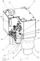
- the in the FIGS. 1 and 2 shown electrohydraulic drive unit comprises as main components a cylinder-piston assembly 1 with vertical axis of movement Y, a hydraulic fluid-storing tank 2, a hydraulic unit 3 with an electric motor 4 and driven by this hydraulic pump 5 and a valve block 6 with a plurality arranged thereon or housed therein hydraulically active elements (in particular valves) and a change-oil filter 20.
- the cylinder-piston assembly 1 comprises in known manner such a linear in a cylinder 7 displaceable, with a piston rod 8 connected piston 9, through which the interior of the cylinder 7 is divided into two working spaces, namely a first hydraulic working space 10 which is so associated with a first movement direction Y1 of the piston, that during this increases its volume, and a second hydraulic working space 11, which is associated with a second movement direction Y2 of the piston, which is opposite to the first movement direction Y1, during which it increases its volume.
- a first hydraulic working space 10 which is so associated with a first movement direction Y1 of the piston, that during this increases its volume
- a second hydraulic working space 11 which is associated with a second movement direction Y2 of the piston, which is opposite to the first movement direction Y1, during which it increases its volume.
- In the existing installation position corresponds to the first direction of movement Y1 of the downward movement of the piston 9 and piston rod 8 and the second direction of movement Y2 their upward movement.
- the tank 2 which is ventilated via a ventilation filter 12, so that ambient pressure prevails therein (so-called "open system”), has an L-shape. He thus has a lateral recess 13 in which the valve block 6 is housed. On one of the side walls of the tank 2, a level sensor 34 is arranged.
- the hydraulic pump 5 is disposed inside the tank 2 ("under oil"). However, the drive 4 serving electric motor 4 is located outside of the tank 2, flanged to the bottom 14. Also in the tank 2 are a suction valve 15 and (with a major part of its volume) a flange and terminal block 16. However, the latter protrudes through corresponding openings in the side wall 17 and the bottom 14 of the tank 2 out of this.
- a first flange 19 for Connection provided with the valve block 6; and on the protruding through the bottom 14 of the tank 2 portion of the flange and terminal block 16 is a second flange 21 for connection to the cylinder 7 of the cylinder-piston assembly 1.
- 21 is respectively a hydraulic interface is provided, which comprises two with the two working spaces 10, 11 of the cylinder-piston assembly 1 communicating working ports A, B.
- the flange and connection block 16 has an opening 22, in which the Nachsaugventil 15 is inserted. This has in turn a connection flange for direct connection with the cylinder 7 of the cylinder-piston assembly 1.
- the Nachsaugventil 15 is hydraulically unlocked, what it over a - within the tank 2 misplaced - control line 23 with a on the flange and terminal block 16th is provided, which in turn communicates via a - the flange and terminal block 16 passing through - channel and provided on the first flange 19 control fluid interface with a control output of the valve block 6.
- a near-ground opening intake 24 is provided at the tank side of the hydraulic pump 5, which forms the suction side in their pumping operation.
- the pressure side of the hydraulic pump 5, at which the pumped hydraulic fluid exits in its pumping operation is connected via a pressure hose 25, which is laid inside the tank 2, to a pressure connection provided on the flange and connection block 16. which, in turn, communicates with a pressurized fluid port of the valve block 6 via a channel passing through the flange and port block 16 and a pressure fluid interface provided on the first flange surface 19.
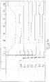
- Fig. 3 The arrangement and connection of the switching valves and other components (suction valve, throttle, pressure limiting valves, filters, etc.) of the hydraulic circuit is in Fig. 3 illustrated. (To avoid any misunderstanding, it should be noted that in Fig. 3 the valve block 6 symbolizing line the physical valve block 6 FIGS. 1 and 2 including the bodily flange and terminal block 16; these two after the FIGS.
- the suction valve 15 By the suction valve 15, the first working space 10 of the cylinder-piston assembly 7 is filled directly from the tank 2.
- This Phase II extends to a - stored in the machine control - switching point, the freely programmable and is suitably chosen near the touchdown of the tool on the workpiece.
- the servomotor 27 is at a standstill.
- the switching valves S2, S4 and S5 are reversed, d. H. the switching valves S2 and S5 are deactivated (switch position "0"), and the switching valve S4 is activated (switch position "I").
- the first working space 10 of the cylinder-piston arrangement 7 is brought into fluid communication with the pressure side 29 of the hydraulic pump 5 via the switching valve S4.
- the second working space 11 of the cylinder-piston arrangement 7 is brought into fluid communication with the tank side via the pressure-limiting valve 30, the switching valve S3, the flow path bT of the switching valve S5 and the oil filter 20.
- the servomotor 27 For force pressing (phase IV), the servomotor 27 is set in operation with its direction of rotation corresponding to the pumping operation of the hydraulic pump 5 (clockwise rotation according to the operating state R *). This operating state of the switching valves S1 to S6 and the servomotor 27 is also maintained over the subsequent holding phase (phase V).
- the servomotor 27 For decompressing the hydraulic fluid in the first working chamber 10 (phase VI), the servomotor 27 is reversed. It now rotates counterclockwise, ie in its braking mode L *, so that hydraulic fluid is conveyed from the first working chamber 10 via the switching valve S4 and the throttle 31 (designed as a nozzle) into the tank 2 in a controlled manner.
- the switching valves S4, S5 and S6 are reversed, d. H.
- the switching valves S4 and S6 are deactivated (switching state "0") and the switching valve S5 is activated (switching state "I").
- the suction valve 15 is opened (unlocked).
- the second working space 11 of the cylinder-piston arrangement 7 is connected to the pressure side 29 of the hydraulic pump 5 via the admission pressure valve 32 and the two switching valves S3 and S2 (in each case through the path protected by the check valve).
- the piston 9 is raised in the rapid-stroke (Phase VII). If necessary, the lifting of the piston 9 can be subdivided into two subphases, in which the rapid lifting is first preceded by a slow lifting. During this first partial phase, the hydraulic fluid displaced from the first working space 10 can flow into the tank 2 via the switching valve S4 (path aT) and the oil filter 20, with the suction valve 15 not yet unlocked.
- the hydraulic pump 5 can, if necessary, be put into operation to hydraulic fluid via the (open) switching valve S1 through the oil filter 20 to promote.
- an oil cooler 33 can be connected to the oil filter 20, connected in series therewith.
- Fig. 3 is illustrated that the switching valves S1, S2, S3, S4 and S6 are equipped with a switch position monitoring 34. In the case of lower safety requirements, this can possibly be dispensed with, in which case the switching valve S3 can also be omitted.
- an optional oil cooler 33 is provided, this is preferably arranged directly outside on one of the side walls of the tank 2.
- the oil supply to the oil cooler 33 takes place via a - inside the tank 2 laid pipe, which is connected to a provided on the flange and terminal block 16 cooling power connection, which in turn via a - the flange and terminal block 16 passing through - channel and at the the first flange 19 provided cooling flow interface with a cooling flow connection of the valve block 6 communicates.
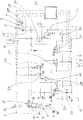
- FIGS. 5 to 7 documented second preferred embodiment of the invention is explained - due to the existing parallels - to a considerable extent by the above explanations to that of the FIGS. 1 to 4 affected first embodiment. To avoid repetition, reference is made to the latter. However, special attention should be drawn to the relevant deviations discussed below as follows:
- the flange and port block 16 ' is not located in the tank, but rather (completely) outside the tank 2'. It is located below the tank 2 ', ie below its bottom 14.
- This allows a particularly compact design.
- Fig. 6 recognizable that in the first embodiment in the decompression phase effective, with the hydraulic pump functionally connected in series throttle is omitted.
- This is related to the (in the second embodiment provided) pressure-dependent control of the decompression by appropriate control of the hydraulic pump 5 in braking operation by the controller, for which purpose the signal of a hydraulic pressure in the first hydraulic working chamber detecting pressure sensor 34 is connected to the controller.
- the filtering of the hydraulic fluid is designed differently.
- a filter unit 35 is provided such that in the pumping operation of the hydraulic pump 5, the entire hydraulic fluid delivered by the latter is cleaned by the filter 20 '. Only when the filter 20 'is obstructed does the hydraulic fluid delivered by the hydraulic pump 5' flow via the "small" bypass 36, in which the check valve 37 acts as a pressure relief valve and opens when the filter 20 'is laden or clogged, in order to prevent filter breakage.
- the hydraulic fluid flows past the filter unit 35 via the "large" bypass 38.
- Fig. 6 shows, for safety reasons, a shut-off valve S7 added. This locks in his non-energized Position the hydraulic pump 5 from the other valve assembly and prevents in this way an unintentional pressure build-up in the system.
Landscapes
- Engineering & Computer Science (AREA)
- Mechanical Engineering (AREA)
- Physics & Mathematics (AREA)
- Fluid Mechanics (AREA)
- General Engineering & Computer Science (AREA)
- Fluid-Pressure Circuits (AREA)
- Details Of Reciprocating Pumps (AREA)
Claims (16)
- Unité d'entraînement hydroélectrique, en particulier pour une utilisation sur une presse automatique, comprenant :- un ensemble vérin-piston (1) comprenant un premier espace de travail hydraulique (10) associé avec un premier sens de déplacement (Y1) du piston (9) et un deuxième espace de travail hydraulique (11) associé avec un deuxième sens opposé de déplacement (Y2) du piston (9),- un réservoir (2; 2') stockant le fluide hydraulique,- une pompe hydraulique (5) à opération dans 2 quadrants qui, en mode de pompage, est entraînée à vitesse variable dans exactement un sens de rotation prédéterminé par un moteur électrique (4) et qui comporte un raccord de réservoir débouchant directement dans le réservoir (2; 2') et un raccord de refoulement (29),- un ensemble de valves qui est disposé entre ledit raccord de refoulement (29) de la pompe hydraulique (5) et ledit ensemble vérin-piston (1) et qui comprend des valves de commutation (S1-S6; S2'-S6', S7) à commande électrique, et- une commande de machine (26) qui agit sur les valves de commutation (S1-S6; S2'-S6', S7) et le moteur électrique (4) et moyennant laquelle les valves de commutation (S1-S6; S2'-S6', S7) sont aptes à être commutées entre une pressurisation dudit premier espace de travail hydraulique (10) et dudit deuxième espace de travail hydraulique (11) dudit ensemble vérin-piston (1) en mode de pompage de la pompe hydraulique (5) par son raccord de refoulement (29),ladite pompe hydraulique (5) étant apte à être commutée par la commande de machine (26) à un mode de freinage présentant un sens de rotation et d'écoulement inverse au mode de pompage.
- Unité d'entraînement hydroélectrique selon la revendication 1, caractérisée en ce que ledit ensemble vérin-piston (1) est orienté de telle façon qu'il a un axe de déplacement (Y) sensiblement vertical, ledit premier sens de déplacement (Y1) correspondant à un mouvement descendant et ledit deuxième sens de déplacement (Y2) correspondant à un mouvement ascendant dudit piston (9).
- Unité d'entraînement hydroélectrique selon la revendication 1 ou la revendication 2, caractérisée en ce que la pompe hydraulique (5), non seulement dans une première phase de déplacement pendant laquelle le deuxième espace de travail hydraulique (11) de l'ensemble vérin-piston (1) est en communication fluidique avec ledit raccord de refoulement (29) de la pompe hydraulique (5), mais encore dans une deuxième phase de déplacement pendant laquelle le premier espace de travail hydraulique (10) de l'ensemble vérin-piston (1) est en communication fluidique avec ledit raccord de refoulement (29) de la pompe hydraulique (5), est apte à être commutée au mode de freinage.
- Unité d'entraînement hydroélectrique selon la revendication 3, caractérisée en ce qu'un étrangleur (31) est prévu qui, en mode de freinage dans la deuxième phase de déplacement, est raccordé en série avec la pompe hydraulique (5).
- Unité d'entraînement hydroélectrique selon l'une quelconque des revendications 1 à 4, caractérisée en ce que la pompe hydraulique (5) est disposée à l'intérieur dudit réservoir (2; 2').
- Unité d'entraînement hydroélectrique selon l'une quelconque des revendications 1 à 5, caractérisée en ce qu'un bloc de raccordement à bride (16) est prévu qui comprend une première surface de bride (19) reliée avec un bloc de valves (6) logeant les valves de commutation (S1-S6; S2'-S6', S7) et une deuxième surface de bride (21) reliée avec le vérin (7) dudit ensemble vérin-piston (1).
- Unité d'entraînement hydroélectrique selon la revendication 6, caractérisée en ce que la majeure partie du volume dudit bloc de raccordement à bride (16) est disposé dans le réservoir (2).
- Unité d'entraînement hydroélectrique selon la revendication 6 ou la revendication 7, caractérisée en ce que ledit bloc de valves (6) est logé dans un évidemment latéral (13) dudit réservoir (2; 2').
- Unité d'entraînement hydroélectrique selon l'une quelconque des revendications 6 à 8, caractérisée en ce qu'une interface hydraulique est prévue sur ladite deuxième surface de bride (21), ladite interface hydraulique comprenant deux raccords de travail (A, B) qui sont en communication avec les deux espaces de travail (10, 11) dudit ensemble vérin-piston (1).
- Unité d'entraînement hydroélectrique selon l'une quelconque des revendications 6 à 9, caractérisée en ce que la pompe hydraulique (5) est raccordée audit bloc de raccordement à bride (16) par l'intermédiaire d'un conduit de refoulement (25) s'étendant à l'intérieur dudit réservoir (2).
- Unité d'entraînement hydroélectrique selon l'une quelconque des revendications 1 à 10, caractérisée en ce qu'un clapet anti-cavitation (15) comprenant un clapet anti-retour hydrauliquement piloté est disposé dans ledit réservoir (2).
- Unité d'entraînement hydroélectrique selon la revendication 11, caractérisée en ce que ledit clapet anti-cavitation (15) comprend une bride de raccordement qui est reliée directement avec le vérin (7) de l'ensemble vérin-piston (1).
- Unité d'entraînement hydroélectrique selon la revendication 11 ou la revendication 12, caractérisée en ce que ledit clapet anti-cavitation (15) est relié, par l'intermédiaire d'un conduit pilote (23), avec une sortie pilote qui est prévue sur ledit bloc de raccordement à bride (16).
- Unité d'entraînement hydroélectrique selon la revendication 6, caractérisée en ce que ledit bloc de raccordement à bride (16') est disposé en dessous dudit réservoir (2').
- Unité d'entraînement hydroélectrique selon la revendication 14, caractérisée en ce qu'un clapet anti-cavitation (15') comprenant un clapet anti-retour hydrauliquement piloté est disposé dans ledit bloc de raccordement à bride (16').
- Unité d'entraînement hydroélectrique selon l'une quelconque des revendications 1 à 15, caractérisée en ce qu'elle comprend une unité de filtration (35) comprenant un filtre (20') destiné à être parcouru, lors du mode de pompage de la pompe hydraulique (5), par la totalité du fluide hydraulique refoulé par la pompe hydraulique (5).
Applications Claiming Priority (3)
| Application Number | Priority Date | Filing Date | Title |
|---|---|---|---|
| DE202015106161.7U DE202015106161U1 (de) | 2015-11-13 | 2015-11-13 | Elektrohydraulische Antriebseinheit |
| DE102016119823.4A DE102016119823A1 (de) | 2015-11-13 | 2016-10-18 | Elektrohydraulische Antriebseinheit |
| PCT/EP2016/077348 WO2017081202A1 (fr) | 2015-11-13 | 2016-11-10 | Unité d'entraînement hydroélectrique |
Publications (2)
| Publication Number | Publication Date |
|---|---|
| EP3317088A1 EP3317088A1 (fr) | 2018-05-09 |
| EP3317088B1 true EP3317088B1 (fr) | 2019-08-14 |
Family
ID=54866550
Family Applications (1)
| Application Number | Title | Priority Date | Filing Date |
|---|---|---|---|
| EP16795020.3A Active EP3317088B1 (fr) | 2015-11-13 | 2016-11-10 | Unité d'entraînement hydroélectrique |
Country Status (5)
| Country | Link |
|---|---|
| EP (1) | EP3317088B1 (fr) |
| CN (1) | CN108136707B (fr) |
| DE (2) | DE202015106161U1 (fr) |
| ES (1) | ES2755813T3 (fr) |
| WO (1) | WO2017081202A1 (fr) |
Families Citing this family (6)
| Publication number | Priority date | Publication date | Assignee | Title |
|---|---|---|---|---|
| DE102016114635B4 (de) | 2016-08-08 | 2018-09-20 | Hoerbiger Automatisierungstechnik Holding Gmbh | Bearbeitungsmaschine |
| DE102016118853B3 (de) | 2016-10-05 | 2017-10-26 | Hoerbiger Automatisierungstechnik Holding Gmbh | Elektrohydraulische Antriebseinheit |
| DE102016118854A1 (de) | 2016-10-05 | 2018-04-05 | Hoerbiger Automatisierungstechnik Holding Gmbh | Elektrohydraulische Antriebseinheit |
| CN108435854A (zh) * | 2018-03-27 | 2018-08-24 | 芜湖卓越空调零部件有限公司 | 一种空调储液器压缩机连接支架成型用曲面液压装置 |
| DE102018126114A1 (de) * | 2018-10-19 | 2020-04-23 | Robert Bosch Gmbh | Hydraulikaggregat |
| DE102018218113A1 (de) | 2018-10-23 | 2020-04-23 | Robert Bosch Gmbh | Hydraulische Steueranordnung |
Family Cites Families (10)
| Publication number | Priority date | Publication date | Assignee | Title |
|---|---|---|---|---|
| EP0103727A1 (fr) | 1982-09-02 | 1984-03-28 | Inventio Ag | Dispositif de réglage de synchronisation pour la commande électrohydraulique d'une presse à plier |
| DE3734329A1 (de) * | 1987-10-10 | 1989-04-20 | Bosch Gmbh Robert | Hydraulische steuereinrichtung fuer eine presse |
| JP3782710B2 (ja) * | 2001-11-02 | 2006-06-07 | 日邦興産株式会社 | 油圧プレス装置 |
| AT8633U1 (de) | 2005-09-19 | 2006-10-15 | Hoerbiger Automatisierungstech | Hydraulikantriebseinheit |
| AT505724B1 (de) | 2007-09-12 | 2010-06-15 | Trumpf Maschinen Austria Gmbh | Antriebsvorrichtung für eine biegepresse |
| DE102009058408A1 (de) | 2009-07-09 | 2011-01-13 | Robert Bosch Gmbh | Elektrohydraulische Steuerung |
| TR200906352A2 (tr) | 2009-08-18 | 2010-12-21 | Demi̇rer Teknoloji̇k Si̇stemler Sanayi̇ Ti̇caret Li̇mi̇ted Şi̇rketi̇ | Hidrolik abkant preslerde enerji tasarrufu sağlayan bir yapılanma. |
| DE102012015118B3 (de) * | 2012-04-17 | 2013-10-10 | Hoerbiger Automatisierungstechnik Holding Gmbh | Maschinenpresse |
| DE102012013098B4 (de) | 2012-06-30 | 2014-08-07 | Hoerbiger Automatisierungstechnik Holding Gmbh | Maschinenpresse |
| DE102013000725B4 (de) | 2013-01-17 | 2024-02-08 | Robert Bosch Gmbh | Elektrohydraulische Steuerung |
-
2015
- 2015-11-13 DE DE202015106161.7U patent/DE202015106161U1/de active Active
-
2016
- 2016-10-18 DE DE102016119823.4A patent/DE102016119823A1/de not_active Withdrawn
- 2016-11-10 WO PCT/EP2016/077348 patent/WO2017081202A1/fr unknown
- 2016-11-10 ES ES16795020T patent/ES2755813T3/es active Active
- 2016-11-10 EP EP16795020.3A patent/EP3317088B1/fr active Active
- 2016-11-10 CN CN201680059698.1A patent/CN108136707B/zh active Active
Non-Patent Citations (1)
| Title |
|---|
| None * |
Also Published As
| Publication number | Publication date |
|---|---|
| WO2017081202A1 (fr) | 2017-05-18 |
| DE202015106161U1 (de) | 2015-11-27 |
| DE102016119823A1 (de) | 2017-05-18 |
| CN108136707B (zh) | 2020-05-29 |
| ES2755813T3 (es) | 2020-04-23 |
| CN108136707A (zh) | 2018-06-08 |
| EP3317088A1 (fr) | 2018-05-09 |
Similar Documents
| Publication | Publication Date | Title |
|---|---|---|
| EP3317088B1 (fr) | Unité d'entraînement hydroélectrique | |
| EP2039582B1 (fr) | Amortisseur hydraulique actif et mécanisme de commande hydraulique | |
| EP3233544B1 (fr) | Châssis de véhicule automobile | |
| EP2838719B1 (fr) | Presse | |
| EP2498982B1 (fr) | Presse | |
| EP2676036B1 (fr) | Système d'entraînement hydraulique sans accumulateur de pression pour un consommateur et comprenant un consommateur, en particulier pour des presses, et procédé permettant de faire fonctionner un tel système d'entraînement hydraulique sans accumulateur de pression | |
| AT516316B1 (de) | Verfahren zur Steuerung einer hydraulisch angetriebenen Maschine | |
| EP3077674B1 (fr) | Système hydraulique | |
| EP1252449A1 (fr) | Procede et dispositif de commande d'un verin hydraulique notamment d'engins de travail | |
| EP2846942B1 (fr) | Presse à filer hydraulique et procédé de fonctionnement d'une presse à filer hydraulique | |
| EP3356683B1 (fr) | Actionneur électrohydraulique | |
| EP3781819B1 (fr) | Dispositif de commande | |
| EP0284831B1 (fr) | Dispositif de commande hydraulique pour des groupes de consommateurs | |
| DE3539220A1 (de) | Steuereinrichtung fuer ein hydrostatisches getriebe | |
| WO2009015502A1 (fr) | Dispositif de commande pour au moins deux commandes hydrauliques | |
| WO2018108615A1 (fr) | Entraînement hydraulique à course rapide et course en charge | |
| EP3837446B1 (fr) | Système actionneur électrohydrostatique à réservoir d'aspiration | |
| WO2017186712A1 (fr) | Arbre hydraulique pour une presse | |
| EP2333351B1 (fr) | Module de levage hydroélectrique | |
| DE102017107994B4 (de) | Kraftfahrzeug-Fahrgestell | |
| EP3523120B1 (fr) | Groupe d'entraînement électo-hydraulique | |
| WO2008083772A1 (fr) | Dispositif de commande pour des consommateurs hydrauliques | |
| EP0559651B1 (fr) | Machine a entrainement hydraulique avec deux cylindres d'entrainement | |
| DE102021006222B3 (de) | Pressenvorrichtung und 2/2-Wege-Proportional-Sitzventil | |
| EP3762616B1 (fr) | Soupape |
Legal Events
| Date | Code | Title | Description |
|---|---|---|---|
| STAA | Information on the status of an ep patent application or granted ep patent |
Free format text: STATUS: UNKNOWN |
|
| STAA | Information on the status of an ep patent application or granted ep patent |
Free format text: STATUS: THE INTERNATIONAL PUBLICATION HAS BEEN MADE |
|
| PUAI | Public reference made under article 153(3) epc to a published international application that has entered the european phase |
Free format text: ORIGINAL CODE: 0009012 |
|
| STAA | Information on the status of an ep patent application or granted ep patent |
Free format text: STATUS: REQUEST FOR EXAMINATION WAS MADE |
|
| 17P | Request for examination filed |
Effective date: 20180119 |
|
| AK | Designated contracting states |
Kind code of ref document: A1 Designated state(s): AL AT BE BG CH CY CZ DE DK EE ES FI FR GB GR HR HU IE IS IT LI LT LU LV MC MK MT NL NO PL PT RO RS SE SI SK SM TR |
|
| AX | Request for extension of the european patent |
Extension state: BA ME |
|
| DAV | Request for validation of the european patent (deleted) | ||
| DAX | Request for extension of the european patent (deleted) | ||
| GRAP | Despatch of communication of intention to grant a patent |
Free format text: ORIGINAL CODE: EPIDOSNIGR1 |
|
| STAA | Information on the status of an ep patent application or granted ep patent |
Free format text: STATUS: GRANT OF PATENT IS INTENDED |
|
| RIC1 | Information provided on ipc code assigned before grant |
Ipc: F15B 11/02 20060101ALI20190220BHEP Ipc: F15B 15/18 20060101ALI20190220BHEP Ipc: F15B 1/26 20060101ALI20190220BHEP Ipc: B30B 15/20 20060101ALI20190220BHEP Ipc: B30B 15/16 20060101AFI20190220BHEP |
|
| INTG | Intention to grant announced |
Effective date: 20190305 |
|
| GRAS | Grant fee paid |
Free format text: ORIGINAL CODE: EPIDOSNIGR3 |
|
| GRAA | (expected) grant |
Free format text: ORIGINAL CODE: 0009210 |
|
| STAA | Information on the status of an ep patent application or granted ep patent |
Free format text: STATUS: THE PATENT HAS BEEN GRANTED |
|
| RAP1 | Party data changed (applicant data changed or rights of an application transferred) |
Owner name: HAWE ALTENSTADT HOLDING GMBH |
|
| AK | Designated contracting states |
Kind code of ref document: B1 Designated state(s): AL AT BE BG CH CY CZ DE DK EE ES FI FR GB GR HR HU IE IS IT LI LT LU LV MC MK MT NL NO PL PT RO RS SE SI SK SM TR |
|
| REG | Reference to a national code |
Ref country code: GB Ref legal event code: FG4D Free format text: NOT ENGLISH |
|
| REG | Reference to a national code |
Ref country code: CH Ref legal event code: EP Ref country code: AT Ref legal event code: REF Ref document number: 1166531 Country of ref document: AT Kind code of ref document: T Effective date: 20190815 |
|
| REG | Reference to a national code |
Ref country code: IE Ref legal event code: FG4D Free format text: LANGUAGE OF EP DOCUMENT: GERMAN |
|
| REG | Reference to a national code |
Ref country code: DE Ref legal event code: R096 Ref document number: 502016006134 Country of ref document: DE |
|
| REG | Reference to a national code |
Ref country code: NL Ref legal event code: MP Effective date: 20190814 |
|
| REG | Reference to a national code |
Ref country code: LT Ref legal event code: MG4D |
|
| PG25 | Lapsed in a contracting state [announced via postgrant information from national office to epo] |
Ref country code: PT Free format text: LAPSE BECAUSE OF FAILURE TO SUBMIT A TRANSLATION OF THE DESCRIPTION OR TO PAY THE FEE WITHIN THE PRESCRIBED TIME-LIMIT Effective date: 20191216 Ref country code: NO Free format text: LAPSE BECAUSE OF FAILURE TO SUBMIT A TRANSLATION OF THE DESCRIPTION OR TO PAY THE FEE WITHIN THE PRESCRIBED TIME-LIMIT Effective date: 20191114 Ref country code: SE Free format text: LAPSE BECAUSE OF FAILURE TO SUBMIT A TRANSLATION OF THE DESCRIPTION OR TO PAY THE FEE WITHIN THE PRESCRIBED TIME-LIMIT Effective date: 20190814 Ref country code: FI Free format text: LAPSE BECAUSE OF FAILURE TO SUBMIT A TRANSLATION OF THE DESCRIPTION OR TO PAY THE FEE WITHIN THE PRESCRIBED TIME-LIMIT Effective date: 20190814 Ref country code: LT Free format text: LAPSE BECAUSE OF FAILURE TO SUBMIT A TRANSLATION OF THE DESCRIPTION OR TO PAY THE FEE WITHIN THE PRESCRIBED TIME-LIMIT Effective date: 20190814 Ref country code: HR Free format text: LAPSE BECAUSE OF FAILURE TO SUBMIT A TRANSLATION OF THE DESCRIPTION OR TO PAY THE FEE WITHIN THE PRESCRIBED TIME-LIMIT Effective date: 20190814 Ref country code: BG Free format text: LAPSE BECAUSE OF FAILURE TO SUBMIT A TRANSLATION OF THE DESCRIPTION OR TO PAY THE FEE WITHIN THE PRESCRIBED TIME-LIMIT Effective date: 20191114 Ref country code: NL Free format text: LAPSE BECAUSE OF FAILURE TO SUBMIT A TRANSLATION OF THE DESCRIPTION OR TO PAY THE FEE WITHIN THE PRESCRIBED TIME-LIMIT Effective date: 20190814 |
|
| PG25 | Lapsed in a contracting state [announced via postgrant information from national office to epo] |
Ref country code: AL Free format text: LAPSE BECAUSE OF FAILURE TO SUBMIT A TRANSLATION OF THE DESCRIPTION OR TO PAY THE FEE WITHIN THE PRESCRIBED TIME-LIMIT Effective date: 20190814 Ref country code: LV Free format text: LAPSE BECAUSE OF FAILURE TO SUBMIT A TRANSLATION OF THE DESCRIPTION OR TO PAY THE FEE WITHIN THE PRESCRIBED TIME-LIMIT Effective date: 20190814 Ref country code: IS Free format text: LAPSE BECAUSE OF FAILURE TO SUBMIT A TRANSLATION OF THE DESCRIPTION OR TO PAY THE FEE WITHIN THE PRESCRIBED TIME-LIMIT Effective date: 20191214 Ref country code: RS Free format text: LAPSE BECAUSE OF FAILURE TO SUBMIT A TRANSLATION OF THE DESCRIPTION OR TO PAY THE FEE WITHIN THE PRESCRIBED TIME-LIMIT Effective date: 20190814 Ref country code: GR Free format text: LAPSE BECAUSE OF FAILURE TO SUBMIT A TRANSLATION OF THE DESCRIPTION OR TO PAY THE FEE WITHIN THE PRESCRIBED TIME-LIMIT Effective date: 20191115 |
|
| REG | Reference to a national code |
Ref country code: ES Ref legal event code: FG2A Ref document number: 2755813 Country of ref document: ES Kind code of ref document: T3 Effective date: 20200423 |
|
| PG25 | Lapsed in a contracting state [announced via postgrant information from national office to epo] |
Ref country code: RO Free format text: LAPSE BECAUSE OF FAILURE TO SUBMIT A TRANSLATION OF THE DESCRIPTION OR TO PAY THE FEE WITHIN THE PRESCRIBED TIME-LIMIT Effective date: 20190814 Ref country code: PL Free format text: LAPSE BECAUSE OF FAILURE TO SUBMIT A TRANSLATION OF THE DESCRIPTION OR TO PAY THE FEE WITHIN THE PRESCRIBED TIME-LIMIT Effective date: 20190814 Ref country code: DK Free format text: LAPSE BECAUSE OF FAILURE TO SUBMIT A TRANSLATION OF THE DESCRIPTION OR TO PAY THE FEE WITHIN THE PRESCRIBED TIME-LIMIT Effective date: 20190814 Ref country code: EE Free format text: LAPSE BECAUSE OF FAILURE TO SUBMIT A TRANSLATION OF THE DESCRIPTION OR TO PAY THE FEE WITHIN THE PRESCRIBED TIME-LIMIT Effective date: 20190814 |
|
| PG25 | Lapsed in a contracting state [announced via postgrant information from national office to epo] |
Ref country code: CZ Free format text: LAPSE BECAUSE OF FAILURE TO SUBMIT A TRANSLATION OF THE DESCRIPTION OR TO PAY THE FEE WITHIN THE PRESCRIBED TIME-LIMIT Effective date: 20190814 Ref country code: SM Free format text: LAPSE BECAUSE OF FAILURE TO SUBMIT A TRANSLATION OF THE DESCRIPTION OR TO PAY THE FEE WITHIN THE PRESCRIBED TIME-LIMIT Effective date: 20190814 Ref country code: IS Free format text: LAPSE BECAUSE OF FAILURE TO SUBMIT A TRANSLATION OF THE DESCRIPTION OR TO PAY THE FEE WITHIN THE PRESCRIBED TIME-LIMIT Effective date: 20200224 Ref country code: SK Free format text: LAPSE BECAUSE OF FAILURE TO SUBMIT A TRANSLATION OF THE DESCRIPTION OR TO PAY THE FEE WITHIN THE PRESCRIBED TIME-LIMIT Effective date: 20190814 |
|
| REG | Reference to a national code |
Ref country code: DE Ref legal event code: R097 Ref document number: 502016006134 Country of ref document: DE |
|
| REG | Reference to a national code |
Ref country code: CH Ref legal event code: PL |
|
| PLBE | No opposition filed within time limit |
Free format text: ORIGINAL CODE: 0009261 |
|
| STAA | Information on the status of an ep patent application or granted ep patent |
Free format text: STATUS: NO OPPOSITION FILED WITHIN TIME LIMIT |
|
| PG2D | Information on lapse in contracting state deleted |
Ref country code: IS |
|
| PG25 | Lapsed in a contracting state [announced via postgrant information from national office to epo] |
Ref country code: LI Free format text: LAPSE BECAUSE OF NON-PAYMENT OF DUE FEES Effective date: 20191130 Ref country code: MC Free format text: LAPSE BECAUSE OF FAILURE TO SUBMIT A TRANSLATION OF THE DESCRIPTION OR TO PAY THE FEE WITHIN THE PRESCRIBED TIME-LIMIT Effective date: 20190814 Ref country code: CH Free format text: LAPSE BECAUSE OF NON-PAYMENT OF DUE FEES Effective date: 20191130 Ref country code: LU Free format text: LAPSE BECAUSE OF NON-PAYMENT OF DUE FEES Effective date: 20191110 |
|
| 26N | No opposition filed |
Effective date: 20200603 |
|
| REG | Reference to a national code |
Ref country code: BE Ref legal event code: MM Effective date: 20191130 |
|
| PG25 | Lapsed in a contracting state [announced via postgrant information from national office to epo] |
Ref country code: SI Free format text: LAPSE BECAUSE OF FAILURE TO SUBMIT A TRANSLATION OF THE DESCRIPTION OR TO PAY THE FEE WITHIN THE PRESCRIBED TIME-LIMIT Effective date: 20190814 |
|
| PG25 | Lapsed in a contracting state [announced via postgrant information from national office to epo] |
Ref country code: FR Free format text: LAPSE BECAUSE OF NON-PAYMENT OF DUE FEES Effective date: 20191130 Ref country code: IE Free format text: LAPSE BECAUSE OF NON-PAYMENT OF DUE FEES Effective date: 20191110 |
|
| PG25 | Lapsed in a contracting state [announced via postgrant information from national office to epo] |
Ref country code: BE Free format text: LAPSE BECAUSE OF NON-PAYMENT OF DUE FEES Effective date: 20191130 |
|
| PG25 | Lapsed in a contracting state [announced via postgrant information from national office to epo] |
Ref country code: CY Free format text: LAPSE BECAUSE OF FAILURE TO SUBMIT A TRANSLATION OF THE DESCRIPTION OR TO PAY THE FEE WITHIN THE PRESCRIBED TIME-LIMIT Effective date: 20190814 |
|
| GBPC | Gb: european patent ceased through non-payment of renewal fee |
Effective date: 20201110 |
|
| PG25 | Lapsed in a contracting state [announced via postgrant information from national office to epo] |
Ref country code: HU Free format text: LAPSE BECAUSE OF FAILURE TO SUBMIT A TRANSLATION OF THE DESCRIPTION OR TO PAY THE FEE WITHIN THE PRESCRIBED TIME-LIMIT; INVALID AB INITIO Effective date: 20161110 Ref country code: MT Free format text: LAPSE BECAUSE OF FAILURE TO SUBMIT A TRANSLATION OF THE DESCRIPTION OR TO PAY THE FEE WITHIN THE PRESCRIBED TIME-LIMIT Effective date: 20190814 |
|
| PG25 | Lapsed in a contracting state [announced via postgrant information from national office to epo] |
Ref country code: GB Free format text: LAPSE BECAUSE OF NON-PAYMENT OF DUE FEES Effective date: 20201110 |
|
| PG25 | Lapsed in a contracting state [announced via postgrant information from national office to epo] |
Ref country code: MK Free format text: LAPSE BECAUSE OF FAILURE TO SUBMIT A TRANSLATION OF THE DESCRIPTION OR TO PAY THE FEE WITHIN THE PRESCRIBED TIME-LIMIT Effective date: 20190814 |
|
| REG | Reference to a national code |
Ref country code: AT Ref legal event code: MM01 Ref document number: 1166531 Country of ref document: AT Kind code of ref document: T Effective date: 20211110 |
|
| PG25 | Lapsed in a contracting state [announced via postgrant information from national office to epo] |
Ref country code: AT Free format text: LAPSE BECAUSE OF NON-PAYMENT OF DUE FEES Effective date: 20211110 |
|
| P01 | Opt-out of the competence of the unified patent court (upc) registered |
Effective date: 20230523 |
|
| PGFP | Annual fee paid to national office [announced via postgrant information from national office to epo] |
Ref country code: ES Payment date: 20231215 Year of fee payment: 8 |
|
| PGFP | Annual fee paid to national office [announced via postgrant information from national office to epo] |
Ref country code: TR Payment date: 20231030 Year of fee payment: 8 Ref country code: IT Payment date: 20231130 Year of fee payment: 8 Ref country code: DE Payment date: 20231128 Year of fee payment: 8 |