EP3317088B1 - Electro-hydraulic drive unit - Google Patents
Electro-hydraulic drive unit Download PDFInfo
- Publication number
- EP3317088B1 EP3317088B1 EP16795020.3A EP16795020A EP3317088B1 EP 3317088 B1 EP3317088 B1 EP 3317088B1 EP 16795020 A EP16795020 A EP 16795020A EP 3317088 B1 EP3317088 B1 EP 3317088B1
- Authority
- EP
- European Patent Office
- Prior art keywords
- drive unit
- unit according
- hydraulic
- cylinder
- flange
- Prior art date
- Legal status (The legal status is an assumption and is not a legal conclusion. Google has not performed a legal analysis and makes no representation as to the accuracy of the status listed.)
- Active
Links
- 239000012530 fluid Substances 0.000 claims description 21
- 238000005086 pumping Methods 0.000 claims description 10
- 230000002441 reversible effect Effects 0.000 claims description 3
- 238000001816 cooling Methods 0.000 description 5
- 238000010586 diagram Methods 0.000 description 5
- 230000008901 benefit Effects 0.000 description 4
- 230000006837 decompression Effects 0.000 description 4
- 238000013461 design Methods 0.000 description 4
- 238000011161 development Methods 0.000 description 4
- 238000003825 pressing Methods 0.000 description 4
- 238000004891 communication Methods 0.000 description 2
- 230000001419 dependent effect Effects 0.000 description 2
- 238000001914 filtration Methods 0.000 description 2
- 238000009434 installation Methods 0.000 description 2
- 238000012986 modification Methods 0.000 description 2
- 230000004048 modification Effects 0.000 description 2
- 230000008859 change Effects 0.000 description 1
- 238000006073 displacement reaction Methods 0.000 description 1
- 230000002349 favourable effect Effects 0.000 description 1
- 238000012423 maintenance Methods 0.000 description 1
- 238000004519 manufacturing process Methods 0.000 description 1
- 238000000034 method Methods 0.000 description 1
- 238000012544 monitoring process Methods 0.000 description 1
- 230000008569 process Effects 0.000 description 1
- 230000009467 reduction Effects 0.000 description 1
- 238000009423 ventilation Methods 0.000 description 1
Images


Classifications
-
- B—PERFORMING OPERATIONS; TRANSPORTING
- B30—PRESSES
- B30B—PRESSES IN GENERAL
- B30B15/00—Details of, or accessories for, presses; Auxiliary measures in connection with pressing
- B30B15/16—Control arrangements for fluid-driven presses
- B30B15/18—Control arrangements for fluid-driven presses controlling the reciprocating motion of the ram
- B30B15/20—Control arrangements for fluid-driven presses controlling the reciprocating motion of the ram controlling the speed of the ram, e.g. the speed of the approach, pressing or return strokes
-
- B—PERFORMING OPERATIONS; TRANSPORTING
- B30—PRESSES
- B30B—PRESSES IN GENERAL
- B30B15/00—Details of, or accessories for, presses; Auxiliary measures in connection with pressing
- B30B15/16—Control arrangements for fluid-driven presses
-
- F—MECHANICAL ENGINEERING; LIGHTING; HEATING; WEAPONS; BLASTING
- F15—FLUID-PRESSURE ACTUATORS; HYDRAULICS OR PNEUMATICS IN GENERAL
- F15B—SYSTEMS ACTING BY MEANS OF FLUIDS IN GENERAL; FLUID-PRESSURE ACTUATORS, e.g. SERVOMOTORS; DETAILS OF FLUID-PRESSURE SYSTEMS, NOT OTHERWISE PROVIDED FOR
- F15B11/00—Servomotor systems without provision for follow-up action; Circuits therefor
- F15B11/02—Systems essentially incorporating special features for controlling the speed or actuating force of an output member
- F15B11/022—Systems essentially incorporating special features for controlling the speed or actuating force of an output member in which a rapid approach stroke is followed by a slower, high-force working stroke
-
- F—MECHANICAL ENGINEERING; LIGHTING; HEATING; WEAPONS; BLASTING
- F15—FLUID-PRESSURE ACTUATORS; HYDRAULICS OR PNEUMATICS IN GENERAL
- F15B—SYSTEMS ACTING BY MEANS OF FLUIDS IN GENERAL; FLUID-PRESSURE ACTUATORS, e.g. SERVOMOTORS; DETAILS OF FLUID-PRESSURE SYSTEMS, NOT OTHERWISE PROVIDED FOR
- F15B15/00—Fluid-actuated devices for displacing a member from one position to another; Gearing associated therewith
- F15B15/18—Combined units comprising both motor and pump
-
- F—MECHANICAL ENGINEERING; LIGHTING; HEATING; WEAPONS; BLASTING
- F15—FLUID-PRESSURE ACTUATORS; HYDRAULICS OR PNEUMATICS IN GENERAL
- F15B—SYSTEMS ACTING BY MEANS OF FLUIDS IN GENERAL; FLUID-PRESSURE ACTUATORS, e.g. SERVOMOTORS; DETAILS OF FLUID-PRESSURE SYSTEMS, NOT OTHERWISE PROVIDED FOR
- F15B1/00—Installations or systems with accumulators; Supply reservoir or sump assemblies
- F15B1/26—Supply reservoir or sump assemblies
-
- F—MECHANICAL ENGINEERING; LIGHTING; HEATING; WEAPONS; BLASTING
- F15—FLUID-PRESSURE ACTUATORS; HYDRAULICS OR PNEUMATICS IN GENERAL
- F15B—SYSTEMS ACTING BY MEANS OF FLUIDS IN GENERAL; FLUID-PRESSURE ACTUATORS, e.g. SERVOMOTORS; DETAILS OF FLUID-PRESSURE SYSTEMS, NOT OTHERWISE PROVIDED FOR
- F15B2211/00—Circuits for servomotor systems
- F15B2211/20—Fluid pressure source, e.g. accumulator or variable axial piston pump
- F15B2211/205—Systems with pumps
- F15B2211/20507—Type of prime mover
- F15B2211/20515—Electric motor
-
- F—MECHANICAL ENGINEERING; LIGHTING; HEATING; WEAPONS; BLASTING
- F15—FLUID-PRESSURE ACTUATORS; HYDRAULICS OR PNEUMATICS IN GENERAL
- F15B—SYSTEMS ACTING BY MEANS OF FLUIDS IN GENERAL; FLUID-PRESSURE ACTUATORS, e.g. SERVOMOTORS; DETAILS OF FLUID-PRESSURE SYSTEMS, NOT OTHERWISE PROVIDED FOR
- F15B2211/00—Circuits for servomotor systems
- F15B2211/20—Fluid pressure source, e.g. accumulator or variable axial piston pump
- F15B2211/205—Systems with pumps
- F15B2211/2053—Type of pump
- F15B2211/20538—Type of pump constant capacity
-
- F—MECHANICAL ENGINEERING; LIGHTING; HEATING; WEAPONS; BLASTING
- F15—FLUID-PRESSURE ACTUATORS; HYDRAULICS OR PNEUMATICS IN GENERAL
- F15B—SYSTEMS ACTING BY MEANS OF FLUIDS IN GENERAL; FLUID-PRESSURE ACTUATORS, e.g. SERVOMOTORS; DETAILS OF FLUID-PRESSURE SYSTEMS, NOT OTHERWISE PROVIDED FOR
- F15B2211/00—Circuits for servomotor systems
- F15B2211/20—Fluid pressure source, e.g. accumulator or variable axial piston pump
- F15B2211/205—Systems with pumps
- F15B2211/2053—Type of pump
- F15B2211/20561—Type of pump reversible
-
- F—MECHANICAL ENGINEERING; LIGHTING; HEATING; WEAPONS; BLASTING
- F15—FLUID-PRESSURE ACTUATORS; HYDRAULICS OR PNEUMATICS IN GENERAL
- F15B—SYSTEMS ACTING BY MEANS OF FLUIDS IN GENERAL; FLUID-PRESSURE ACTUATORS, e.g. SERVOMOTORS; DETAILS OF FLUID-PRESSURE SYSTEMS, NOT OTHERWISE PROVIDED FOR
- F15B2211/00—Circuits for servomotor systems
- F15B2211/30—Directional control
- F15B2211/305—Directional control characterised by the type of valves
- F15B2211/3056—Assemblies of multiple valves
- F15B2211/30565—Assemblies of multiple valves having multiple valves for a single output member, e.g. for creating higher valve function by use of multiple valves like two 2/2-valves replacing a 5/3-valve
- F15B2211/3057—Assemblies of multiple valves having multiple valves for a single output member, e.g. for creating higher valve function by use of multiple valves like two 2/2-valves replacing a 5/3-valve having two valves, one for each port of a double-acting output member
-
- F—MECHANICAL ENGINEERING; LIGHTING; HEATING; WEAPONS; BLASTING
- F15—FLUID-PRESSURE ACTUATORS; HYDRAULICS OR PNEUMATICS IN GENERAL
- F15B—SYSTEMS ACTING BY MEANS OF FLUIDS IN GENERAL; FLUID-PRESSURE ACTUATORS, e.g. SERVOMOTORS; DETAILS OF FLUID-PRESSURE SYSTEMS, NOT OTHERWISE PROVIDED FOR
- F15B2211/00—Circuits for servomotor systems
- F15B2211/60—Circuit components or control therefor
- F15B2211/665—Methods of control using electronic components
- F15B2211/6651—Control of the prime mover, e.g. control of the output torque or rotational speed
-
- F—MECHANICAL ENGINEERING; LIGHTING; HEATING; WEAPONS; BLASTING
- F15—FLUID-PRESSURE ACTUATORS; HYDRAULICS OR PNEUMATICS IN GENERAL
- F15B—SYSTEMS ACTING BY MEANS OF FLUIDS IN GENERAL; FLUID-PRESSURE ACTUATORS, e.g. SERVOMOTORS; DETAILS OF FLUID-PRESSURE SYSTEMS, NOT OTHERWISE PROVIDED FOR
- F15B2211/00—Circuits for servomotor systems
- F15B2211/70—Output members, e.g. hydraulic motors or cylinders or control therefor
- F15B2211/775—Combined control, e.g. control of speed and force for providing a high speed approach stroke with low force followed by a low speed working stroke with high force, e.g. for a hydraulic press
Definitions
- the present invention relates to an electro-hydraulic drive unit, in particular for use on a machine press.
- Electro-hydraulic drive units such as are suitable and intended in particular for use on machine presses (namely for moving the respective tool up and down) are known in various designs and designs.
- the respective drive units are designed so that the piston (at least in one of the two directions of movement) can be moved at different speeds, namely on the one hand with a rapid traverse (with comparatively low achievable pressing force) and on the other hand with a power gear (with comparatively high achievable pressing force)
- Two fundamentally different concepts of the electro-hydraulic drive of machine presses differ in that for the rapid downwards movement of the tool carrier / tool unit either an active loading of the sink working space of the cylinder-piston unit (s) from the (respective) hydraulic unit is required , Namely, because the permanently acting restoring force of a spring device is overcome, or the tool carrier / tool unit due to their own weight until the contact of the tool with the workpiece (braked) drops and only for the subsequent power stroke of the sink working space Cylinder-piston unit (s) from the (
- WO 2011/003506 A1 relevant to the prior art include the WO 2011/003506 A1 . US 2010/0212521 A1 . AT 8633 U1 . DE 102012013098 A1 . WO 2011/021986 A1 . EP 103727 A1 and DE 102013000725 A1 ,
- the present invention is concerned with electro-hydraulic drive units, as are suitable for machine presses according to the second of the above-mentioned concepts (rapid downwards movement of the tool carrier / tool unit due to its own weight).
- Typical such electrohydraulic drive units include a cylinder-piston arrangement having a first hydraulic working space associated with a first direction of movement of the piston and a second hydraulic working space associated with an opposite second direction of movement of the piston, a hydraulic fluid storing tank, a hydraulic pump driven by an electric motor, one between the two Hydraulic pump and the cylinder-piston assembly switched, electrically controllable switching valves comprehensive valve assembly and acting on the switching valves and the electric motor machine control means of which the switching valves between acting on the first hydraulic working space and the second hydraulic working space of the cylinder-piston assembly in the pumping operation the hydraulic pump from the pressure port can be reversed.
- Electro-hydraulic drive devices of the type in question here must in practice a number of Meet requirements that are partly in conflict with each other. Depending on the individual installation situation, more or less pronounced demands are demanded, in particular efficiency, compact dimensions, ease of maintenance, longevity, reliability, low production costs, high energy efficiency, operational safety, high dynamics, stable operating behavior even under strongly changing conditions and low noise emission.
- the present invention has set itself the task of providing an electro-hydraulic drive unit, which forms a balanced, particularly practical compromise in terms of typical requirements, as they exist in particular in applications of machine presses.
- the hydraulic pump is designed as a 2-quadrant hydraulic pump, which by means of a (in particular designed as a servo motor) electric motor in pumping operation (For an active movement of the piston in both directions of movement, ie downwards for pressing in power and up to raise the tool carrier / tool unit) is driven variable speed in exactly one predetermined direction of rotation and a directly (ie typically without further controls) in the tank opening tank port and a pressure port, wherein the hydraulic pump further by means of the engine control in a braking operation with the Pump operation reverse rotational and flow direction is reversible.
- a powerful, reliable and reliable electro-hydraulic drive unit can be provided with comparatively low expenditure on equipment, which also meets the other requirements set out above to a high degree.
- the cylinder-piston arrangement is oriented with at least substantially vertical movement axis, wherein the first direction of movement of a downward movement and the second direction of movement corresponds to an upward movement of the piston.
- the hydraulic pump is both in a first movement phase (rapid-down), while (via the valve assembly) is a flow connection of the second hydraulic working space of the cylinder-piston assembly with the pressure port of the hydraulic pump, as well as in a second movement phase (decompression-up ), in which there is a flow connection of the first hydraulic working space of the cylinder-piston arrangement with the pressure connection of the hydraulic pump, in the braking operation uncontrollable.
- a throttle for example in the form of a nozzle
- a throttle is provided, which is connected in braking mode in the second movement phase in series with the hydraulic pump. This relieves the hydraulic pump and limits its stress during braking operation during the second movement phase, so that possibly operating conditions (overspeeding) impairing process safety are avoided.
- a pressure-dependent control of the speed of the hydraulic pump driving - or in this mode - braking electric motor takes place in the decompression phase, ie in the second phase of movement during braking operation, a pressure-dependent control of the speed of the hydraulic pump driving - or in this mode - braking electric motor.
- a pressure sensor is provided in this case, which detects the pressure prevailing in the first hydraulic working space pressure and the signal is switched to the machine control.
- the hydraulic pump is disposed inside lying in the tank. This permits a course of the pressure line which follows the pressure outlet of the hydraulic pump, which is a considerable advantage from the point of view of operating safety and is furthermore favorable for minimizing the risk of external leaks. In addition, this is under aspects of low noise emission and a constant cooling of the hydraulic pump advantage.
- a flange and connection block is provided with a first flange for connection to a valve block housing the switching valves and a second flange surface for connection to the cylinder of the cylinder-piston arrangement.
- the flange and connection block can be arranged in particular to a predominant part of its volume in the tank and adjacent only with the two flange surfaces Edge areas more or less protrude from this.
- the flange and connection block is arranged outside the tank, more preferably below its bottom.
- the hydraulic pump can be connected in particular via a pressure line extending inside the tank with a pressure connection provided on the flange and connection block, which in turn is connected via a channel to a pressure connection provided on the first flange surface; and on the first as well as the second flange surface may be provided in each case a hydraulic interface which comprises two communicating with the two working spaces of the cylinder-piston arrangement working ports.
- valve block is housed in a lateral recess of the tank.
- valve block receiving recess may be arranged in one of the corner regions of the tank.
- Yet another preferred embodiment of the invention is characterized in that a hydraulically releasable Nachsaugventil is arranged in the tank.
- a hydraulically releasable Nachsaugventil is arranged in the tank.
- the suction valve can in turn a connection flange for direct connection with the cylinder of the cylinder-piston assembly respectively.
- the suction valve is completely integrated in the - arranged outside the tank - flange and connection block; only the latter is connected via its second flange directly with the cylinder of the cylinder-piston assembly.
- the suction valve can be connected via a control line with a control output provided on the flange and connection block.
- the control output of the flange and connection block is connected via a channel with a control fluid interface to the first flange in connection.
- an electro-hydraulic drive unit having distinct advantages (particularly in the case of use as a machine press drive) can be provided.
- These include in particular: By factory pre-assembled and tested units, which are equipped with a mechanical interface to the respective cylinder-piston assembly and thus easy to connect to the latter, there are minimal assembly and commissioning times on the machine.
- the piping-reduced design and the consistent avoidance of external piping result in the greatest possible reliability and the reduction of the risk of external leaks.
- the drive unit uses a small amount of hydraulic fluid. It has a low temperature dependence on a very high energy efficiency, so that usually neither a designated oil cooling time is provided, nor an oil cooler is needed. So can the drive unit have particularly small dimensions.
- the noise is minimal.
- a return stroke of the tool is possible at working speed.
- Additional functions such as tool clamping and crowning can be integrated into the drive unit without any additional effort or connected to it.
- the drive unit requires no accumulator and no proportional directional control valves. Equally, it is absolutely not necessary to use any pressure sensors, although those may definitely be provided with advantage in certain embodiments of the drive unit according to the invention (see above).
- a variable displacement pump is not required. It is possible to realize highly dynamic machine presses (eg press brakes) with a rapid traverse speed of, for example, 200-230 mm / sec.
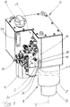
- the in the FIGS. 1 and 2 shown electrohydraulic drive unit comprises as main components a cylinder-piston assembly 1 with vertical axis of movement Y, a hydraulic fluid-storing tank 2, a hydraulic unit 3 with an electric motor 4 and driven by this hydraulic pump 5 and a valve block 6 with a plurality arranged thereon or housed therein hydraulically active elements (in particular valves) and a change-oil filter 20.
- the cylinder-piston assembly 1 comprises in known manner such a linear in a cylinder 7 displaceable, with a piston rod 8 connected piston 9, through which the interior of the cylinder 7 is divided into two working spaces, namely a first hydraulic working space 10 which is so associated with a first movement direction Y1 of the piston, that during this increases its volume, and a second hydraulic working space 11, which is associated with a second movement direction Y2 of the piston, which is opposite to the first movement direction Y1, during which it increases its volume.
- a first hydraulic working space 10 which is so associated with a first movement direction Y1 of the piston, that during this increases its volume
- a second hydraulic working space 11 which is associated with a second movement direction Y2 of the piston, which is opposite to the first movement direction Y1, during which it increases its volume.
- In the existing installation position corresponds to the first direction of movement Y1 of the downward movement of the piston 9 and piston rod 8 and the second direction of movement Y2 their upward movement.
- the tank 2 which is ventilated via a ventilation filter 12, so that ambient pressure prevails therein (so-called "open system”), has an L-shape. He thus has a lateral recess 13 in which the valve block 6 is housed. On one of the side walls of the tank 2, a level sensor 34 is arranged.
- the hydraulic pump 5 is disposed inside the tank 2 ("under oil"). However, the drive 4 serving electric motor 4 is located outside of the tank 2, flanged to the bottom 14. Also in the tank 2 are a suction valve 15 and (with a major part of its volume) a flange and terminal block 16. However, the latter protrudes through corresponding openings in the side wall 17 and the bottom 14 of the tank 2 out of this.
- a first flange 19 for Connection provided with the valve block 6; and on the protruding through the bottom 14 of the tank 2 portion of the flange and terminal block 16 is a second flange 21 for connection to the cylinder 7 of the cylinder-piston assembly 1.
- 21 is respectively a hydraulic interface is provided, which comprises two with the two working spaces 10, 11 of the cylinder-piston assembly 1 communicating working ports A, B.
- the flange and connection block 16 has an opening 22, in which the Nachsaugventil 15 is inserted. This has in turn a connection flange for direct connection with the cylinder 7 of the cylinder-piston assembly 1.
- the Nachsaugventil 15 is hydraulically unlocked, what it over a - within the tank 2 misplaced - control line 23 with a on the flange and terminal block 16th is provided, which in turn communicates via a - the flange and terminal block 16 passing through - channel and provided on the first flange 19 control fluid interface with a control output of the valve block 6.
- a near-ground opening intake 24 is provided at the tank side of the hydraulic pump 5, which forms the suction side in their pumping operation.
- the pressure side of the hydraulic pump 5, at which the pumped hydraulic fluid exits in its pumping operation is connected via a pressure hose 25, which is laid inside the tank 2, to a pressure connection provided on the flange and connection block 16. which, in turn, communicates with a pressurized fluid port of the valve block 6 via a channel passing through the flange and port block 16 and a pressure fluid interface provided on the first flange surface 19.
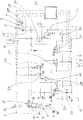
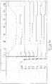
- Fig. 3 The arrangement and connection of the switching valves and other components (suction valve, throttle, pressure limiting valves, filters, etc.) of the hydraulic circuit is in Fig. 3 illustrated. (To avoid any misunderstanding, it should be noted that in Fig. 3 the valve block 6 symbolizing line the physical valve block 6 FIGS. 1 and 2 including the bodily flange and terminal block 16; these two after the FIGS.
- the suction valve 15 By the suction valve 15, the first working space 10 of the cylinder-piston assembly 7 is filled directly from the tank 2.
- This Phase II extends to a - stored in the machine control - switching point, the freely programmable and is suitably chosen near the touchdown of the tool on the workpiece.
- the servomotor 27 is at a standstill.
- the switching valves S2, S4 and S5 are reversed, d. H. the switching valves S2 and S5 are deactivated (switch position "0"), and the switching valve S4 is activated (switch position "I").
- the first working space 10 of the cylinder-piston arrangement 7 is brought into fluid communication with the pressure side 29 of the hydraulic pump 5 via the switching valve S4.
- the second working space 11 of the cylinder-piston arrangement 7 is brought into fluid communication with the tank side via the pressure-limiting valve 30, the switching valve S3, the flow path bT of the switching valve S5 and the oil filter 20.
- the servomotor 27 For force pressing (phase IV), the servomotor 27 is set in operation with its direction of rotation corresponding to the pumping operation of the hydraulic pump 5 (clockwise rotation according to the operating state R *). This operating state of the switching valves S1 to S6 and the servomotor 27 is also maintained over the subsequent holding phase (phase V).
- the servomotor 27 For decompressing the hydraulic fluid in the first working chamber 10 (phase VI), the servomotor 27 is reversed. It now rotates counterclockwise, ie in its braking mode L *, so that hydraulic fluid is conveyed from the first working chamber 10 via the switching valve S4 and the throttle 31 (designed as a nozzle) into the tank 2 in a controlled manner.
- the switching valves S4, S5 and S6 are reversed, d. H.
- the switching valves S4 and S6 are deactivated (switching state "0") and the switching valve S5 is activated (switching state "I").
- the suction valve 15 is opened (unlocked).
- the second working space 11 of the cylinder-piston arrangement 7 is connected to the pressure side 29 of the hydraulic pump 5 via the admission pressure valve 32 and the two switching valves S3 and S2 (in each case through the path protected by the check valve).
- the piston 9 is raised in the rapid-stroke (Phase VII). If necessary, the lifting of the piston 9 can be subdivided into two subphases, in which the rapid lifting is first preceded by a slow lifting. During this first partial phase, the hydraulic fluid displaced from the first working space 10 can flow into the tank 2 via the switching valve S4 (path aT) and the oil filter 20, with the suction valve 15 not yet unlocked.
- the hydraulic pump 5 can, if necessary, be put into operation to hydraulic fluid via the (open) switching valve S1 through the oil filter 20 to promote.
- an oil cooler 33 can be connected to the oil filter 20, connected in series therewith.
- Fig. 3 is illustrated that the switching valves S1, S2, S3, S4 and S6 are equipped with a switch position monitoring 34. In the case of lower safety requirements, this can possibly be dispensed with, in which case the switching valve S3 can also be omitted.
- an optional oil cooler 33 is provided, this is preferably arranged directly outside on one of the side walls of the tank 2.
- the oil supply to the oil cooler 33 takes place via a - inside the tank 2 laid pipe, which is connected to a provided on the flange and terminal block 16 cooling power connection, which in turn via a - the flange and terminal block 16 passing through - channel and at the the first flange 19 provided cooling flow interface with a cooling flow connection of the valve block 6 communicates.
- FIGS. 5 to 7 documented second preferred embodiment of the invention is explained - due to the existing parallels - to a considerable extent by the above explanations to that of the FIGS. 1 to 4 affected first embodiment. To avoid repetition, reference is made to the latter. However, special attention should be drawn to the relevant deviations discussed below as follows:
- the flange and port block 16 ' is not located in the tank, but rather (completely) outside the tank 2'. It is located below the tank 2 ', ie below its bottom 14.
- This allows a particularly compact design.
- Fig. 6 recognizable that in the first embodiment in the decompression phase effective, with the hydraulic pump functionally connected in series throttle is omitted.
- This is related to the (in the second embodiment provided) pressure-dependent control of the decompression by appropriate control of the hydraulic pump 5 in braking operation by the controller, for which purpose the signal of a hydraulic pressure in the first hydraulic working chamber detecting pressure sensor 34 is connected to the controller.
- the filtering of the hydraulic fluid is designed differently.
- a filter unit 35 is provided such that in the pumping operation of the hydraulic pump 5, the entire hydraulic fluid delivered by the latter is cleaned by the filter 20 '. Only when the filter 20 'is obstructed does the hydraulic fluid delivered by the hydraulic pump 5' flow via the "small" bypass 36, in which the check valve 37 acts as a pressure relief valve and opens when the filter 20 'is laden or clogged, in order to prevent filter breakage.
- the hydraulic fluid flows past the filter unit 35 via the "large" bypass 38.
- Fig. 6 shows, for safety reasons, a shut-off valve S7 added. This locks in his non-energized Position the hydraulic pump 5 from the other valve assembly and prevents in this way an unintentional pressure build-up in the system.
Description
Die vorliegende Erfindung betrifft eine elektrohydraulische Antriebseinheit, insbesondere zur Verwendung an einer Maschinenpresse.The present invention relates to an electro-hydraulic drive unit, in particular for use on a machine press.
Elektrohydraulische Antriebseinheiten, wie sie insbesondere zur Verwendung an Maschinenpressen (namentlich zum Auf- und Abbewegen des betreffenden Werkzeugs) geeignet und bestimmt sind, sind in verschiedenen Ausführungen und Bauweisen bekannt. Typischerweise sind die betreffenden Antriebseinheiten dahingehend ausgelegt, dass der Kolben (zumindest in einer der beiden Bewegungsrichtungen) mit unterschiedlichen Geschwindigkeiten bewegt werden kann, nämlich einerseits mit einem Eilgang (mit vergleichsweise geringer erzielbarer Presskraft) und andererseits mit einem Kraftgang (mit vergleichsweise hoher erzielbarer Presskraft). Zwei grundlegend verschiedene Konzepte des elektrohydraulischen Antriebs von Maschinenpressen unterscheiden sich dahingehend, dass für die Eil-Abwärtsbewegung der Werkzeugträger/Werkzeug-Einheit entweder eine aktive Beaufschlagung des Senken-Arbeitsraumes der Zylinder-Kolben-Einheit(en) aus dem (jeweiligen) Hydraulikaggregat erforderlich ist, namentlich weil die permanent wirkende Rückstellkraft einer Federeinrichtung zu überwinden ist, oder aber die Werkzeugträger/Werkzeug-Einheit aufgrund ihres Eigengewichts bis zum Kontakt des Werkzeugs mit dem Werkstück (gebremst) absinkt und allein für den anschließenden Kraftgang der Senken-Arbeitsraumes der Zylinder-Kolben-Einheit(en) aus dem (jeweiligen) Hydraulikaggregat beaufschlagt wird. Zum insoweit einschlägigen Stand der Technik zählen beispielsweise die
Die vorliegende Erfindung befasst sich mit elektrohydraulischen Antriebseinheiten, wie sie sich für Maschinenpressen gemäß der zweiten der weiter oben angesprochenen Konzeptionen (Eil-Abwärtsbewegung der Werkzeugträger/Werkzeug-Einheit infolge des Eigengewichts) eignen. Typische derartige elektrohydraulische Antriebseinheiten umfassen eine Zylinder-Kolben-Anordnung mit einem einer ersten Bewegungsrichtung des Kolbens zugeordneten ersten hydraulischen Arbeitsraum und einem einer entgegengesetzten zweiten Bewegungsrichtung des Kolbens zugeordneten zweiten hydraulischen Arbeitsraum, einen Hydraulikflüssigkeit bevorratenden Tank, eine mittels eines Elektromotors angetriebene Hydraulikpumpe, eine zwischen die Hydraulikpumpe und die Zylinder-Kolben-Anordnung geschaltete, elektrisch ansteuerbare Schaltventile umfassende Ventilanordnung und eine auf die Schaltventile und den Elektromotor einwirkende Maschinensteuerung, mittels derer die Schaltventile zwischen einer Beaufschlagung des ersten hydraulischen Arbeitsraums und des zweiten hydraulischen Arbeitsraums der Zylinder-Kolben-Anordnung im Pumpbetrieb der Hydraulikpumpe aus deren Druckanschluss umsteuerbar sind.The present invention is concerned with electro-hydraulic drive units, as are suitable for machine presses according to the second of the above-mentioned concepts (rapid downwards movement of the tool carrier / tool unit due to its own weight). Typical such electrohydraulic drive units include a cylinder-piston arrangement having a first hydraulic working space associated with a first direction of movement of the piston and a second hydraulic working space associated with an opposite second direction of movement of the piston, a hydraulic fluid storing tank, a hydraulic pump driven by an electric motor, one between the two Hydraulic pump and the cylinder-piston assembly switched, electrically controllable switching valves comprehensive valve assembly and acting on the switching valves and the electric motor machine control means of which the switching valves between acting on the first hydraulic working space and the second hydraulic working space of the cylinder-piston assembly in the pumping operation the hydraulic pump from the pressure port can be reversed.
Elektrohydraulische Antriebseinrichtungen der hier in Rede stehenden Art müssen in der Praxis eine Reihe von Anforderungen erfüllen, die teilweise in einem Konflikt zueinander stehen. Gefordert werden, je nach der individuellen Einbausituation mehr oder weniger ausgeprägt, insbesondere Leistungsfähigkeit, kompakte Abmessungen, Wartungsfreundlichkeit, Langlebigkeit, Zuverlässigkeit, geringe Herstellungskosten, hohe Energieeffizienz, Betriebssicherheit, hohe Dynamik, stabiles Betriebsverhalten auch unter stark wechselnden Bedingungen und geringe Lärmemission.Electro-hydraulic drive devices of the type in question here must in practice a number of Meet requirements that are partly in conflict with each other. Depending on the individual installation situation, more or less pronounced demands are demanded, in particular efficiency, compact dimensions, ease of maintenance, longevity, reliability, low production costs, high energy efficiency, operational safety, high dynamics, stable operating behavior even under strongly changing conditions and low noise emission.
Die vorliegende Erfindung hat sich zur Aufgabe gemacht, eine elektrohydraulische Antriebseinheit bereitzustellen, die im Hinblick auf typische Anforderungen, wie sie insbesondere bei Anwendungen an Maschinenpressen bestehen, einen ausgewogenen, besonders praxistauglichen Kompromiss bildet.The present invention has set itself the task of providing an electro-hydraulic drive unit, which forms a balanced, particularly practical compromise in terms of typical requirements, as they exist in particular in applications of machine presses.
Gelöst wird diese Aufgabenstellung gemäß der vorliegenden Erfindung, indem, wie im Anspruch 1 angegeben, bei einer die weiter oben dargelegten Merkmale aufweisenden elektrohydraulischen Antriebseinheit die Hydraulikpumpe als 2-Quadranten-Hydraulikpumpe ausgeführt ist, welche mittels eines (insbesondere als Servomotor ausgeführten) Elektromotors im Pumpbetrieb (für eine aktive Bewegung des Kolbens in beide Bewegungsrichtungen, d. h. abwärts zum Pressen im Kraftgang sowie aufwärts zum Anheben der Werkzeugträger/Werkzeug-Einheit) in genau einer vorgegebenen Drehrichtung drehzahlvariabel angetrieben ist und einen unmittelbar (d. h. typischerweise ohne weitergehende Steuerelemente) im Tank mündenden Tankanschluss und einen Druckanschluss aufweist, wobei die Hydraulikpumpe weiterhin mittels der Maschinensteuerung in einen Bremsbetrieb mit zum Pumpbetrieb umgekehrter Dreh- und Durchströmungsrichtung umsteuerbar ist. Auf diese Weise lässt sich mit vergleichsweise geringem apparativen Aufwand eine leistungsfähige, zuverlässige und betriebssichere elektrohydraulische Antriebseinheit bereitstellen, welche auch die weiteren weiter oben dargelegten Anforderungen in hohem Maße erfüllt.This object is achieved according to the present invention by, as indicated in
Besonders bevorzugt ist bei der erfindungsgemäßen elektrohydraulischen Antriebseinheit die Zylinder-Kolben-Anordnung mit zumindest im Wesentlichen senkrechter Bewegungsachse orientiert, wobei die erste Bewegungsrichtung einer Abwärtsbewegung und die zweite Bewegungsrichtung einer Aufwärtsbewegung des Kolbens entspricht. Und die Hydraulikpumpe ist sowohl in einer ersten Bewegungsphase (Eilgang-Abwärts), während (über die Ventilanordnung) eine Strömungsverbindung des zweiten hydraulischen Arbeitsraums der Zylinder-Kolben-Anordnung mit dem Druckanschluss der Hydraulikpumpe besteht, als auch in einer zweiten Bewegungsphase (Dekompression-Aufwärts), in der eine Strömungsverbindung des ersten hydraulischen Arbeitsraums der Zylinder-Kolben-Anordnung mit dem Druckanschluss der Hydraulikpumpe besteht, in den Bremsbetrieb unsteuerbar.Particularly preferably, in the electro-hydraulic drive unit according to the invention, the cylinder-piston arrangement is oriented with at least substantially vertical movement axis, wherein the first direction of movement of a downward movement and the second direction of movement corresponds to an upward movement of the piston. And the hydraulic pump is both in a first movement phase (rapid-down), while (via the valve assembly) is a flow connection of the second hydraulic working space of the cylinder-piston assembly with the pressure port of the hydraulic pump, as well as in a second movement phase (decompression-up ), in which there is a flow connection of the first hydraulic working space of the cylinder-piston arrangement with the pressure connection of the hydraulic pump, in the braking operation uncontrollable.
Besonders bevorzugt ist dabei eine Drossel (beispielsweise in Form einer Düse) vorgesehen, welche im Bremsbetrieb in der zweiten Bewegungsphase in Reihe mit der Hydraulikpumpe geschaltet ist. Dies entlastet die Hydraulikpumpe und limitiert deren Beanspruchung im Bremsbetrieb während der zweiten Bewegungsphase, so dass möglicherweise die Prozesssicherheit beeinträchtigende Betriebszustände (Überdrehen) vermieden werden. In alternativer Weiterbildung, die ohne eine derartige Drossel auskommt, erfolgt in der Dekompressionsphase, d. h. in der zweiten Bewegungsphase während des Bremsbetriebs eine druckabhängige Steuerung der Drehzahl des die Hydraulikpumpe antreibenden - bzw. bei diesem Betriebsmodus - bremsenden Elektromotors. Insoweit ist in diesem Falle ein Drucksensor vorgesehen, der den im ersten hydraulischen Arbeitsraum herrschenden Druck erfasst und dessen Signal auf die Maschinensteuerung geschaltet ist.Particularly preferred is a throttle (for example in the form of a nozzle) is provided, which is connected in braking mode in the second movement phase in series with the hydraulic pump. This relieves the hydraulic pump and limits its stress during braking operation during the second movement phase, so that possibly operating conditions (overspeeding) impairing process safety are avoided. In Alternative development that does not require such a throttle, takes place in the decompression phase, ie in the second phase of movement during braking operation, a pressure-dependent control of the speed of the hydraulic pump driving - or in this mode - braking electric motor. In that regard, a pressure sensor is provided in this case, which detects the pressure prevailing in the first hydraulic working space pressure and the signal is switched to the machine control.
Gemäß einer anderen bevorzugten Weiterbildung der Erfindung ist die Hydraulikpumpe innen liegend in dem Tank angeordnet. Dies erlaubt einen innerhalb des Tanks verlegten Verlauf der sich an den Druckausgang der Hydraulikpumpe anschließenden Druckleitung, was unter Gesichtspunkten der Betriebssicherheit einen erheblichen Vorteil darstellt und weiterhin günstig ist zur Minimierung des Risikos externer Leckagen. Zudem ist dies unter Aspekten einer geringen Geräuschemission und einer ständigen Kühlung der Hydraulikpumpe von Vorteil.According to another preferred embodiment of the invention, the hydraulic pump is disposed inside lying in the tank. This permits a course of the pressure line which follows the pressure outlet of the hydraulic pump, which is a considerable advantage from the point of view of operating safety and is furthermore favorable for minimizing the risk of external leaks. In addition, this is under aspects of low noise emission and a constant cooling of the hydraulic pump advantage.
Eine wiederum andere bevorzugte Weiterbildung der erfindungsgemäßen elektrohydraulischen Antriebseinheit zeichnet sich dadurch aus, dass ein Flansch- und Anschlussblock vorgesehen ist mit einer ersten Flanschfläche zur Verbindung mit einem die Schaltventile beherbergenden Ventilblock und einer zweiten Flanschfläche zur Verbindung mit dem Zylinder der Zylinder-Kolben-Anordnung. Der Flansch- und Anschlussblock kann dabei insbesondere zu einem überwiegenden Teil seines Volumens in dem Tank angeordnet sein und nur mit den beiden Flanschflächen benachbarten Randbereichen mehr oder weniger weit aus diesem herausragen. Gemäß einer alternativen bevorzugten Weiterbildung ist der Flansch- und Anschlussblock indessen außerhalb des Tanks angeordnet, und zwar besonders bevorzugt unterhalb von dessen Boden. Im Sinne obiger Ausführungen kann die Hydraulikpumpe dabei insbesondere über eine innerhalb des Tanks verlaufende Druckleitung mit einem an dem Flansch- und Anschlussblock vorgesehenen Druckanschluss verbunden sein, welcher seinerseits über einen Kanal mit einem an der ersten Flanschfläche vorgesehenen Druckanschluss in Verbindung steht; und an der ersten wie auch der zweiten Flanschfläche kann jeweils eine hydraulische Schnittstelle vorgesehen sein, welche zwei mit den beiden Arbeitsräumen der Zylinder-Kolben-Anordnung kommunizierende Arbeitsanschlüsse umfasst.Yet another preferred development of the electro-hydraulic drive unit according to the invention is characterized in that a flange and connection block is provided with a first flange for connection to a valve block housing the switching valves and a second flange surface for connection to the cylinder of the cylinder-piston arrangement. The flange and connection block can be arranged in particular to a predominant part of its volume in the tank and adjacent only with the two flange surfaces Edge areas more or less protrude from this. According to an alternative preferred development, however, the flange and connection block is arranged outside the tank, more preferably below its bottom. In the sense of the above embodiments, the hydraulic pump can be connected in particular via a pressure line extending inside the tank with a pressure connection provided on the flange and connection block, which in turn is connected via a channel to a pressure connection provided on the first flange surface; and on the first as well as the second flange surface may be provided in each case a hydraulic interface which comprises two communicating with the two working spaces of the cylinder-piston arrangement working ports.
Gemäß einer wiederum anderen bevorzugten Weiterbildung der Erfindung ist der Ventilblock in einer seitlichen Aussparung des Tanks untergebracht. Insbesondere kann eine derartige, den Ventilblock aufnehmende Aussparung in einem der Eckbereiche des Tanks angeordnet sein.According to yet another preferred embodiment of the invention, the valve block is housed in a lateral recess of the tank. In particular, such, the valve block receiving recess may be arranged in one of the corner regions of the tank.
Eine nochmals andere bevorzugte Weiterbildung der Erfindung zeichnet sich dadurch aus, dass in dem Tank ein hydraulisch entsperrbares Nachsaugventil angeordnet ist. Besonders vorteilhaft ist die Anordnung des Nachsaugventils in einem Durchbruch des weiter oben beschriebenen, zu einem überwiegenden Teil seines Volumens in dem Tank angeordneten Flansch- und Anschlussblocks; das Nachsaugventil kann dabei seinerseits einen Anschlussflansch zur unmittelbaren Verbindung mit dem Zylinder der Zylinder-Kolben-Anordnung aufweisen. In einer bevorzugten alternativen Weiterbildung ist das Nachsaugventil vollständig in den - außerhalb des Tanks angeordneten - Flansch- und Anschlussblock integriert; nur letzterer ist dabei über seine zweite Flanschfläche unmittelbar mit dem Zylinder der Zylinder-Kolben-Anordnung verbunden. Und das Nachsaugventil kann über eine Steuerleitung mit einem an dem Flansch- und Anschlussblock vorgesehenen Steuerausgang verbunden sein. Der Steuerausgang des Flansch- und Anschlussblocks steht dabei über einen Kanal mit einer Steuerfluid-Schnittstelle an der ersten Flanschfläche in Verbindung.Yet another preferred embodiment of the invention is characterized in that a hydraulically releasable Nachsaugventil is arranged in the tank. Particularly advantageous is the arrangement of the Nachsaugventils in a breakthrough of the above-described, arranged to a major part of its volume in the tank flange and terminal block; The suction valve can in turn a connection flange for direct connection with the cylinder of the cylinder-piston assembly respectively. In a preferred alternative development, the suction valve is completely integrated in the - arranged outside the tank - flange and connection block; only the latter is connected via its second flange directly with the cylinder of the cylinder-piston assembly. And the suction valve can be connected via a control line with a control output provided on the flange and connection block. The control output of the flange and connection block is connected via a channel with a control fluid interface to the first flange in connection.
Aus den vorstehenden Erläuterungen ist ersichtlich, dass sich in Anwendung der vorliegenden Erfindung eine elektrohydraulische Antriebseinheit mit ausgeprägten Vorteilen (insbesondere im Falle der Verwendung als Antrieb einer Maschinenpresse) bereitstellen lässt. Hierzu zählen insbesondere: Durch werksseitig vormontierte und geprüfte Einheiten, welche mit einer mechanischen Schnittstelle zur jeweiligen Zylinder-Kolben-Anordnung ausgestattet und somit leicht mit letzterem zu verbinden sind, ergeben sich minimale Montage- und Inbetriebnahmezeiten an der Maschine. Durch das rohrleitungsreduzierte Design und den konsequenten Verzicht auf externe Verrohrung ergeben sich größtmögliche Zuverlässigkeit und die Reduzierung der Gefahr externer Leckagen. Die Antriebseinheit kommt mit einer geringen Menge an Hydraulikflüssigkeit aus. Sie verfügt bei geringer Temperaturabhängigkeit über eine sehr hohe energetische Effizienz, so dass in der Regel weder eine ausgewiesene Ölkühlzeit vorzusehen ist, noch ein Ölkühler benötigt wird. So kann die Antriebseinheit besonders geringe Baumaße aufweisen. Die Geräuschentwicklung ist minimal. Mittels der Ventilsteuerung ist ein Rückhub des Werkzeugs in Arbeitsgeschwindigkeit möglich. Hierdurch sind besonders kurze Zykluszeiten und eine dementsprechend hohe Produktivität möglich. Zusatzfunktionen wie Werkzeugklemmung und Bombierung lassen sich ohne Mehraufwand in die Antriebseinheit integrieren bzw. an diese anbinden. Die Antriebseinheit kommt ohne Druckspeicher und ohne proportionale Wegeventile aus. Ebenso wenig bedarf es zwingend irgend welcher Drucksensoren, wobei solche allerdings bei bestimmten Ausgestaltungen der erfindungsgemäße Antriebseinheit durchaus mit Vorteil vorgesehen sein können (s. o.). Auch eine Verstellpumpe ist nicht erforderlich. Es lassen sich hochdynamische Maschinenpressen (z. B. Abkantpressen) realisieren mit einer Eilgang-Geschwindigkeit von beispielsweise 200-230mm/sec.It will be appreciated from the foregoing discussion that in application of the present invention, an electro-hydraulic drive unit having distinct advantages (particularly in the case of use as a machine press drive) can be provided. These include in particular: By factory pre-assembled and tested units, which are equipped with a mechanical interface to the respective cylinder-piston assembly and thus easy to connect to the latter, there are minimal assembly and commissioning times on the machine. The piping-reduced design and the consistent avoidance of external piping result in the greatest possible reliability and the reduction of the risk of external leaks. The drive unit uses a small amount of hydraulic fluid. It has a low temperature dependence on a very high energy efficiency, so that usually neither a designated oil cooling time is provided, nor an oil cooler is needed. So can the drive unit have particularly small dimensions. The noise is minimal. By means of the valve control a return stroke of the tool is possible at working speed. As a result, particularly short cycle times and a correspondingly high productivity are possible. Additional functions such as tool clamping and crowning can be integrated into the drive unit without any additional effort or connected to it. The drive unit requires no accumulator and no proportional directional control valves. Equally, it is absolutely not necessary to use any pressure sensors, although those may definitely be provided with advantage in certain embodiments of the drive unit according to the invention (see above). A variable displacement pump is not required. It is possible to realize highly dynamic machine presses (eg press brakes) with a rapid traverse speed of, for example, 200-230 mm / sec.
Im Folgenden wird die vorliegende Erfindung anhand zweier in der Zeichnung veranschaulichter bevorzugter Ausführungsbeispiele näher erläutert. Dabei zeigt
- Fig. 1
- in perspektivischer Ansicht eine elektrohydraulische Antriebseinheit nach einem ersten Ausführungsbeispiel der Erfindung ohne die zugehörige Maschinensteuerung,
- Fig. 2
- die elektrohydraulische Antriebseinheit nach
Fig. 1 bei teilweise geschnittenen Seitenwänden des Tanks zur Veranschaulichung von dessen Einbauten, allerdings ohne die Zylinder-Kolben-Einheit, - Fig. 3
- den Hydraulikschaltplan zu der elektrohydraulischen Antriebseinheit nach den
Figuren 12 , - Fig. 4
- in Form eines Diagramms die Ansteuerung der Schaltventile und des Elektromotors der elektrohydraulischen Antriebseinheit nach den
Figuren 1 bis 3 - Fig. 5
- in perspektivischer Ansicht eine elektrohydraulische Antriebseinheit nach einem zweiten Ausführungsbeispiel der Erfindung ohne die zugehörige Maschinensteuerung,
- Fig. 6
- den Hydraulikschaltplan zu der elektrohydraulischen Antriebseinheit nach
Fig. 5 (ohne die zugehörige Maschinensteuerung) und - Fig. 7
- ein die Ansteuerung der Schaltventile und des Elektromotors der elektrohydraulischen Antriebseinheit nach den
Figuren 56 und die sich ergebende Bewegung des Kolbens veranschaulichendes Funktionsdiagramm.
- Fig. 1
- in a perspective view of an electro-hydraulic drive unit according to a first embodiment of the invention without the associated machine control,
- Fig. 2
- the electro-hydraulic drive unit after
Fig. 1 with partially cut side walls of the tank to illustrate its internals, but without the cylinder-piston unit, - Fig. 3
- the hydraulic circuit diagram to the electro-hydraulic drive unit after the
FIGS. 1 and2 . - Fig. 4
- in the form of a diagram, the control of the switching valves and the electric motor of the electro-hydraulic drive unit according to the
FIGS. 1 to 3 and the resulting movement of the piston, - Fig. 5
- a perspective view of an electro-hydraulic drive unit according to a second embodiment of the invention without the associated machine control,
- Fig. 6
- the hydraulic circuit diagram to the electro-hydraulic drive unit according to
Fig. 5 (without the associated machine control) and - Fig. 7
- a control of the switching valves and the electric motor of the electro-hydraulic drive unit after the
Figures 5 and6 and the resulting movement of the piston illustrating functional diagram.
Die in den
Der Tank 2, der über einen Belüftungsfilter 12 belüftet ist, so dass in ihm Umgebungsdruck herrscht (sog. "offenes System"), weist eine L-Form auf. Er verfügt somit über eine seitliche Aussparung 13, in welcher der Ventilblock 6 untergebracht ist. An einer der Seitenwände des Tanks 2 ist ein Füllstandssensor 34 angeordnet.The
Die Hydraulikpumpe 5 ist innen in dem Tank 2 ("unter Öl") angeordnet. Der ihrem Antrieb dienende Elektromotor 4 befindet sich allerdings außerhalb des Tanks 2, an dessen Boden 14 angeflanscht. Ebenfalls in dem Tank 2 befinden sich ein Nachsaugventil 15 sowie (mit einem überwiegenden Teil seines Volumens) ein Flansch- und Anschlussblock 16. Letzterer ragt allerdings durch entsprechende Öffnungen in der Seitenwand 17 und dem Boden 14 des Tanks 2 aus diesem heraus. An dem durch die Seitenwand 17 des Tanks herausragenden Abschnitt 18 des Flansch- und Anschlussblocks 16 ist eine erste Flanschfläche 19 zur Verbindung mit dem Ventilblock 6 vorgesehen; und an dem durch den Boden 14 des Tanks 2 herausragenden Abschnitt des Flansch- und Anschlussblocks 16 befindet sich eine zweite Flanschfläche 21 zur Verbindung mit dem Zylinder 7 der Zylinder-Kolben-Anordnung 1. An der ersten sowie der zweiten Flanschfläche 19, 21 ist jeweils eine hydraulische Schnittstelle vorgesehen, welche zwei mit den beiden Arbeitsräumen 10, 11 der Zylinder-Kolben-Anordnung 1 kommunizierende Arbeitsanschlüsse A, B umfasst.The
Der Flansch- und Anschlussblock 16 weist einen Durchbruch 22 auf, in welchen das Nachsaugventil 15 eingesetzt ist. Dieses verfügt seinerseits über einen Anschlussflansch zur unmittelbaren Verbindung mit dem Zylinder 7 der Zylinder-Kolben-Anordnung 1. Das Nachsaugventil 15 ist hydraulisch entsperrbar, wozu es über eine - innerhalb des Tanks 2 verlegte - Steuerleitung 23 mit einem an dem Flansch- und Anschlussblock 16 vorgesehenen Steueranschluss verbunden ist, welcher seinerseits über einen - den Flansch- und Anschlussblock 16 durchsetzenden - Kanal und eine an der ersten Flanschfläche 19 vorgesehene Steuerfluid-Schnittstelle mit einem Steuerausgang des Ventilblocks 6 kommuniziert.The flange and
An der Tankseite der Hydraulikpumpe 5, welche in deren Pumpbetrieb die Saugseite bildet, ist ein bodennah mündender Ansaugstutzen 24 vorgesehen. Die Druckseite der Hydraulikpumpe 5, an der in deren Pumpbetrieb die geförderte Hydraulikflüssigkeit austritt, ist demgegenüber über einen - innerhalb des Tanks 2 verlegten - Druckschlauch 25 mit einem an dem Flansch- und Anschlussblock 16 vorgesehenen Druckanschluss verbunden, welcher seinerseits über einen den Flansch- und Anschlussblock 16 durchsetzenden Kanal und eine an der ersten Flanschfläche 19 vorgesehene Druckfluid-Schnittstelle mit einem Druckfluid-Anschluss des Ventilblocks 6 kommuniziert.At the tank side of the
Die Anordnung und Verschaltung der Schaltventile und sonstigen Komponenten (Nachsaugventil, Drossel, Druckbegrenzungsventile, Filter, etc.) der Hydraulikschaltung ist in
Und zwar ist in während des Haltens das Kolbens im oberen Totpunkt (Phase I) der Servomotor 27 im Stillstand (Betriebszustand "0"); und keines der sechs Schaltventile S1 bis S6 ist aktiviert, so dass alle Schaltventile die in
Zur Bewegung Eil-Abwärts von Kolben 9 und Kolbenstange 8 (Phase II) sind mit Ausnahme des Schaltventils S4 sämtliche Schaltventile, d. h. die Schaltventile S1, S2, S3, S5 und S6 aktiviert (Schaltstellung "I"). Der zweite Arbeitsraum 11 (Heben-Arbeitsraum) der Zylinder-KolbenEinheit 7 steht über die (geöffneten) Schaltventile S2 und S3 und das gemäß bP geöffnete Schaltventil S5 mit dem Druckanschluss 29 der Hydraulikpumpe 5 in Verbindung. Der Servomotor 27 dreht im Linkslauf (Betriebszustand L*), d. h. in seinem Bremsbetrieb, um die durch das Eigengewicht der von der Antriebseinheit angetriebenen, mit der Kolbenstange 8 verbundenen angetriebenen Maschinenkomponente (Werkzeugträger plus Werkzeug) induzierte Abwärtsbewegung des Kolbens 9 gesteuert zu bremsen. Durch das Nachsaugventil 15 wird der erste Arbeitsraum 10 der Zylinder-Kolben-Anordnung 7 direkt aus dem Tank 2 gefüllt. Diese Phase II erstreckt sich bis zu einem - in der Maschinensteuerung hinterlegten - Umschaltpunkt, der frei programmierbar und zweckmäßigerweise nahe dem Aufsetzpunkt des Werkzeugs auf dem Werkstück gewählt ist.For the movement Eil-down of
In der Lastwechselphase III befindet sich der Servomotor 27 im Stillstand. Die Schaltventile S2, S4 und S5 werden umgesteuert, d. h. die Schaltventile S2 und S5 werden deaktiviert (Schaltstellung "0"), und das Schaltventil S4 wird aktiviert (Schaltstellung "I"). Auf diese Weise wird der erste Arbeitsraum 10 der Zylinder-Kolben-Anordnung 7 über das Schaltventil S4 mit der Druckseite 29 der Hydraulikpumpe 5 in Strömungsverbindung gebracht. Der zweite Arbeitsraum 11 der Zylinder-Kolben-Anordnung 7 wird demgegenüber über das Druckbegrenzungsventil 30, das Schaltventil S3, den Strömungspfad bT des Schaltventils S5 und den Ölfilter 20 mit der Tankseite in Strömungsverbindung gebracht.In the load change phase III, the
Zum Kraftpressen (Phase IV) wird der Servomotor 27 mit seiner dem Pumpbetrieb der Hydraulikpumpe 5 entsprechenden Drehrichtung (Rechtslauf gemäß Betriebszustand R*) in Betrieb gesetzt. Dieser Betriebszustand der Schaltventile S1 bis S6 und des Servomotors 27 wird auch über die anschließende Haltephase (Phase V) aufrechterhalten.For force pressing (phase IV), the
Zum Dekomprimieren der in dem ersten Arbeitsraum 10 befindlichen Hydraulikflüssigkeit (Phase VI) wird der Servomotor 27 umgesteuert. Er dreht nun im Linkslauf, d. h. in seinem Bremsbetrieb L*, so dass Hydraulikflüssigkeit gesteuert aus dem ersten Arbeitsraum 10 über das Schaltventil S4 und die (als Düse ausgeführte) Drossel 31 in den Tank 2 gefördert wird.For decompressing the hydraulic fluid in the first working chamber 10 (phase VI), the
Am Ende der Dekompressionsphase werden die Schaltventile S4, S5 und S6 umgesteuert, d. h. die Schaltventile S4 und S6 werden deaktiviert (Schaltzustand "0") und das Schaltventil S5 wird aktiviert (Schaltzustand "I"). Infolge seiner Beaufschlagung mit Steuerdruck über das Schaltventil S6 (Pfad Pb) wird das Nachsaugventil 15 geöffnet (entsperrt). Und der zweite Arbeitsraum 11 der Zylinder-Kolben-Anordnung 7 ist über das Vordruckventil 32 und die beiden Schaltventile S3 und S2 (jeweils durch den mittels des Rückschlagventils abgesicherten Pfad) mit der Druckseite 29 der Hydraulikpumpe 5 verbunden. Durch Umsteuern des Servomotors 27 in Rechtslauf, d. h. Betrieb mit seiner dem Pumpbetrieb der Hydraulikpumpe entsprechenden Drehrichtung (Betriebszustand R*) wird der Kolben 9 im Eil-Hub angehoben (Phase VII). Bedarfsweise kann das Anheben des Kolbens 9 in zwei Teilphasen unterteilt werden, indem dem Eil-Heben zunächst ein langsames Heben vorgeschaltet ist. Während dieser ersten Teilphase kann, bei noch nicht entsperrtem Nachsaugventil 15, die aus dem ersten Arbeitsraum 10 verdrängte Hydraulikflüssigkeit über das Schaltventil S4 (Pfad aT) und den Ölfilter 20 in den Tank 2 abfließen.At the end of the decompression phase, the switching valves S4, S5 and S6 are reversed, d. H. the switching valves S4 and S6 are deactivated (switching state "0") and the switching valve S5 is activated (switching state "I"). As a result of its application of control pressure via the switching valve S6 (path Pb), the
Bei Erreichen des oberen Totpunktes (OT) geht der Servomotor 27 in Stillstand über; und die Schaltventile S1 und S5 werden umgesteuert, so dass nun wieder sämtliche Schaltventile deaktiviert sind (Haltephase VIII, analog der Haltephase I zu Beginn des Zyklus'; s. o.).Upon reaching the top dead center (TDC), the
In der Haltephase I, VIII kann die Hydraulikpumpe 5 bedarfsweise in Betrieb genommen werden, um Hydraulikflüssigkeit über das (geöffnete) Schaltventil S1 durch den Ölfilter 20 zu fördern. Optional kann sich an den Ölfilter 20, mit diesem in Reihe geschaltet, ein Ölkühler 33 anschließen.In the holding phase I, VIII, the
Zu der in den
In
Ist, wie oben erwähnt und in
Das durch die
Der Flansch- und Anschlussblock 16' ist nicht in dem Tank angeordnet, sondern vielmehr (vollständig) außerhalb des Tanks 2'. Er befindet sich nämlich unterhalb des Tanks 2', d. h. unterhalb von dessen Boden 14. Anders als nach dem ersten Ausführungsbeispiel, bei dem ein selbständig funktionstüchtiges Nachsaugventil in eine Aussparung bzw. einen Durchbruch des Flansch- und Anschlussblock eingesetzt ist, ist bei dem zweiten Ausführungsbeispiel nach den
The flange and port block 16 'is not located in the tank, but rather (completely) outside the tank 2'. It is located below the tank 2 ', ie below its bottom 14. Unlike in the first embodiment, in which a self-functional suction valve is inserted into a recess or an opening of the flange and connection block is in the second embodiment after the
Weiterhin ist in
Anders gestaltet ist bei dem zweiten Ausführungsbeispiel auch die Filterung der Hydraulikflüssigkeit. Hier ist eine Filtereinheit 35 dergestalt vorgesehen, dass im Pumpbetrieb der Hydraulikpumpe 5 die gesamte von letzterer geförderte Hydraulikflüssigkeit durch den Filter 20' gereinigt wird. Nur bei Verstopfung des Filters 20' strömt die von der Hydraulikpumpe 5' geförderte Hydraulikflüssigkeit über den "kleinen" Bypass 36, in dem das Rückschlagventil 37 wie ein Druckbegrenzungsventil wirkt und bei beladenem bzw. verstopften Filter 20' öffnet, um einem Filterbruch vorzubeugen. Im Bremsbetrieb der Hydraulikpumpe 5' strömt die Hydraulikflüssigkeit über den "großen" Bypass 38 an der Filtereinheit 35 vorbei.In the second embodiment, the filtering of the hydraulic fluid is designed differently. Here, a filter unit 35 is provided such that in the pumping operation of the
Infolge der vorstehend beschriebenen Ausführung der Filterung der Hydraulikflüssigkeit ist weiterhin teilweise die Funktion des bei dem ersten Ausführungsbeispiel vorgesehenen Schaltventils S1 entfallen; denn es gibt bei dem zweiten Ausführungsbeispiel keinen reinen Umwälz-Filterbetrieb mehr. Damit könnte das zweite Ausführungsbeispiel mit einem Schaltventil weniger auskommen als das erste Ausführungsbeispiel. Allerdings ist, wie
Hinzuweisen ist schließlich auf den Wegfall eines gesonderten Ölkühlers; denn ein solcher ist bei dem dargestellten zweiten Ausführungsbeispiel nicht erforderlich.Attention should finally be drawn to the omission of a separate oil cooler; because such is not required in the illustrated second embodiment.
Claims (16)
- Electrohydraulic drive unit, in particular for use on a machine press, comprising- a cylinder-piston arrangement (1) having a first hydraulic working chamber (10) assigned to a first direction of movement (Y1) of the piston (9) and a second hydraulic working chamber (11) assigned to an opposite second direction of movement (Y2) of the piston (9),- a tank storing hydraulic fluid (2; 2'),- a 2-quadrant hydraulic pump (5) which is driven by means of an electric motor (4) in pumping operation in exactly one predetermined direction of rotation in variable rotational speed and which has a tank connection opening directly into the tank (2; 2') and a pressure connection (29),- a valve arrangement which is connected between the pressure connection (29) of the hydraulic pump (5) and the cylinder-piston arrangement (1) and which comprises a plurality of electrically controllable switching valves (S1- S6; S2' -S6', S7),- and a machine controller (26) which acts on the switching valves (S1 - S6; S2' - S6' ,S7) and the electric motor (4) and by means of which the switching valves (S1 - S6; S2' - S6', S7) are switchable between a loading of the first hydraulic working chamber (10) and the second hydraulic working chamber (11) of the cylinder-piston arrangement (1) during the pumping operation of the hydraulic pump (5) from the pressure connection (29),wherein the hydraulic pump (5) is switchable by means of the machine controller (26) into a braking operation with the direction of rotation and flow reverse to the pump operation.
- Electrohydraulic drive unit according to claim 1, characterized in that the cylinder-piston arrangement (1) is oriented with an at least substantially perpendicular axis of movement (Y), the first direction of movement (Y1) corresponding to a downward movement and the second direction of movement (Y2) corresponding to an upward movement of the piston (9).
- Electrohydraulic drive unit according to claim 1 or claim 2, characterized in that the hydraulic pump (5) can be switched over into braking operation both in a first movement phase, while a flow connection of the second hydraulic working chamber (11) of the cylinder-piston arrangement (1) with the pressure connection (29) of the hydraulic pump (5) exists, and in a second movement phase, in which a flow connection of the first hydraulic working chamber (10) of the cylinder-piston arrangement (1) with the pressure connection (29) of the hydraulic pump (5) exists, into braking operation.
- Electrohydraulic drive unit according to claim 3, characterized in that a throttle (31) is provided which, in braking operation, is connected in series with the hydraulic pump (5) in the second movement phase.
- Electrohydraulic drive unit according to one of claims 1 to 4, characterized in that the hydraulic pump (5) is disposed on the inside in the tank (2; 2').
- Electrohydraulic drive unit according to one of claims 1 to 5, characterized in that a flange and connection block (16) is provided with a first flange surface (19) for connection to a valve block (6) accommodating the switching valves (S1 - S6; S2' - S6', S7) and a second flange surface (21) for connection to the cylinder (7) of the cylinder-piston arrangement (1).
- Electrohydraulic drive unit according to claim 6, characterized in that the flange and connection block (16) is arranged in the tank (2) to a predominant part of its volume.
- Electrohydraulic drive unit according to claim 6 or claim 7, characterized in that the valve block (6) is disposed in a lateral recess (13) of the tank (2; 2').
- Electrohydraulic drive unit according to one of claims 6 to 8, characterized in that a hydraulic interface is provided on the second flange face (21), which comprises two working connections (A, B) communicating with the two working chambers (10, 11) of the cylinder-piston arrangement (1).
- Electrohydraulic drive unit according to one of claims 6 to 9, characterized in that the hydraulic pump (5) is connected to the flange and connection block (16) via a pressure line (25) running inside the tank (2).
- Electrohydraulic drive unit according to one of claims 1 to 10, characterized in that a suction valve (15) with a hydraulically unlockable non-return valve is arranged in the tank (2).
- Electrohydraulic drive unit according to claim 11, characterized in that the suction valve (15) has a connecting flange for direct connection to the cylinder (7) of the cylinder-piston arrangement (1).
- Electrohydraulic drive unit according to claim 11 or claim 12, characterized in that the suction valve (15) is connected via a control line (23) to a control output provided on the flange and connection block (16).
- Electrohydraulic drive unit according to claim 6, characterized in that the flange and connection block (16') is arranged below the tank (2').
- Electrohydraulic drive unit according to claim 14, characterized in that a suction valve (15') with a hydraulically unlockable non-return valve (15') is disposed into the flange and connection block (16').
- Electrohydraulic drive unit according to one of claims 1 to 15, characterized in that it comprises a filter unit (35) with a filter (20') through which the entire hydraulic fluid conveyed by the hydraulic pump (5) flows during pumping operation of the hydraulic pump (5).
Applications Claiming Priority (3)
| Application Number | Priority Date | Filing Date | Title |
|---|---|---|---|
| DE202015106161.7U DE202015106161U1 (en) | 2015-11-13 | 2015-11-13 | Electrohydraulic drive unit |
| DE102016119823.4A DE102016119823A1 (en) | 2015-11-13 | 2016-10-18 | Electrohydraulic drive unit |
| PCT/EP2016/077348 WO2017081202A1 (en) | 2015-11-13 | 2016-11-10 | Electro-hydraulic drive unit |
Publications (2)
| Publication Number | Publication Date |
|---|---|
| EP3317088A1 EP3317088A1 (en) | 2018-05-09 |
| EP3317088B1 true EP3317088B1 (en) | 2019-08-14 |
Family
ID=54866550
Family Applications (1)
| Application Number | Title | Priority Date | Filing Date |
|---|---|---|---|
| EP16795020.3A Active EP3317088B1 (en) | 2015-11-13 | 2016-11-10 | Electro-hydraulic drive unit |
Country Status (5)
| Country | Link |
|---|---|
| EP (1) | EP3317088B1 (en) |
| CN (1) | CN108136707B (en) |
| DE (2) | DE202015106161U1 (en) |
| ES (1) | ES2755813T3 (en) |
| WO (1) | WO2017081202A1 (en) |
Families Citing this family (6)
| Publication number | Priority date | Publication date | Assignee | Title |
|---|---|---|---|---|
| DE102016114635B4 (en) | 2016-08-08 | 2018-09-20 | Hoerbiger Automatisierungstechnik Holding Gmbh | processing machine |
| DE102016118853B3 (en) | 2016-10-05 | 2017-10-26 | Hoerbiger Automatisierungstechnik Holding Gmbh | Electrohydraulic drive unit |
| DE102016118854A1 (en) | 2016-10-05 | 2018-04-05 | Hoerbiger Automatisierungstechnik Holding Gmbh | Electrohydraulic drive unit |
| CN108435854A (en) * | 2018-03-27 | 2018-08-24 | 芜湖卓越空调零部件有限公司 | A kind of air conditioning liquid reservoir compressor connecting bracket molding curved surface hydraulic device |
| DE102018126114A1 (en) * | 2018-10-19 | 2020-04-23 | Robert Bosch Gmbh | Hydraulic unit |
| DE102018218113A1 (en) | 2018-10-23 | 2020-04-23 | Robert Bosch Gmbh | Hydraulic control arrangement |
Family Cites Families (10)
| Publication number | Priority date | Publication date | Assignee | Title |
|---|---|---|---|---|
| EP0103727A1 (en) | 1982-09-02 | 1984-03-28 | Inventio Ag | Synchronization control apparatus for the electro-hydraulic drive of a press brake |
| DE3734329A1 (en) * | 1987-10-10 | 1989-04-20 | Bosch Gmbh Robert | HYDRAULIC CONTROL DEVICE FOR A PRESS |
| JP3782710B2 (en) * | 2001-11-02 | 2006-06-07 | 日邦興産株式会社 | Hydraulic press device |
| AT8633U1 (en) | 2005-09-19 | 2006-10-15 | Hoerbiger Automatisierungstech | HYDRAULIC DRIVE UNIT |
| AT505724B1 (en) | 2007-09-12 | 2010-06-15 | Trumpf Maschinen Austria Gmbh | DRIVE DEVICE FOR A BEND PRESS |
| DE102009058408A1 (en) | 2009-07-09 | 2011-01-13 | Robert Bosch Gmbh | Electrohydraulic control |
| TR200906352A2 (en) | 2009-08-18 | 2010-12-21 | Demi̇rer Teknoloji̇k Si̇stemler Sanayi̇ Ti̇caret Li̇mi̇ted Şi̇rketi̇ | Energy saving structure in hydraulic press brakes. |
| DE102012015118B3 (en) * | 2012-04-17 | 2013-10-10 | Hoerbiger Automatisierungstechnik Holding Gmbh | machine press |
| DE102012013098B4 (en) | 2012-06-30 | 2014-08-07 | Hoerbiger Automatisierungstechnik Holding Gmbh | machine press |
| DE102013000725B4 (en) | 2013-01-17 | 2024-02-08 | Robert Bosch Gmbh | Electro-hydraulic control |
-
2015
- 2015-11-13 DE DE202015106161.7U patent/DE202015106161U1/en active Active
-
2016
- 2016-10-18 DE DE102016119823.4A patent/DE102016119823A1/en not_active Withdrawn
- 2016-11-10 ES ES16795020T patent/ES2755813T3/en active Active
- 2016-11-10 WO PCT/EP2016/077348 patent/WO2017081202A1/en unknown
- 2016-11-10 EP EP16795020.3A patent/EP3317088B1/en active Active
- 2016-11-10 CN CN201680059698.1A patent/CN108136707B/en active Active
Non-Patent Citations (1)
| Title |
|---|
| None * |
Also Published As
| Publication number | Publication date |
|---|---|
| EP3317088A1 (en) | 2018-05-09 |
| DE102016119823A1 (en) | 2017-05-18 |
| WO2017081202A1 (en) | 2017-05-18 |
| DE202015106161U1 (en) | 2015-11-27 |
| CN108136707A (en) | 2018-06-08 |
| ES2755813T3 (en) | 2020-04-23 |
| CN108136707B (en) | 2020-05-29 |
Similar Documents
| Publication | Publication Date | Title |
|---|---|---|
| EP3317088B1 (en) | Electro-hydraulic drive unit | |
| EP2039582B1 (en) | Active hydraulic damper and hydraulic actuator | |
| EP3233544B1 (en) | Motor vehicle chassis | |
| EP2838719B1 (en) | Machine press | |
| EP2498982B1 (en) | Machine press | |
| EP2676036B1 (en) | Pressure-accumulator-free hydraulic drive arrangement for and comprising a consumer, in particular for presses, and method for operating a pressure-accumulator-free hydraulic drive arrangement of said type | |
| AT516316B1 (en) | Method for controlling a hydraulically driven machine | |
| EP3077674B1 (en) | Hydraulic arrangement | |
| WO2001057405A1 (en) | Method and device for controlling a lift cylinder, especially of working machines | |
| EP2846942B1 (en) | Hydraulic extrusion press and method for operating a hydraulic extrusion press | |
| EP3356683B1 (en) | Electrohydraulic actuator unit | |
| EP3781819B1 (en) | Control device | |
| DE3539220A1 (en) | CONTROL DEVICE FOR A HYDROSTATIC GEARBOX | |
| EP0284831B1 (en) | Hydraulic control device for groups of consumers | |
| WO2009015502A1 (en) | Control device for at least two hydraulic drives | |
| WO2018108615A1 (en) | Hydraulic drive with fast stroke and load stroke | |
| EP3837446B1 (en) | Electrohydrostatic actuator system with an expansion reservoir | |
| WO2017186712A1 (en) | Hydraulic spindle for a press | |
| EP2333351B1 (en) | Electro-hydraulic lifting module | |
| DE102017107994B4 (en) | Motor vehicle chassis | |
| EP3523120B1 (en) | Electro-hydraulic drive unit | |
| WO2008083772A1 (en) | Controlling device for hydraulic consumers | |
| EP0559651B1 (en) | Hydraulically driven machine with two drive cylinders | |
| DE102021006222B3 (en) | Press device and 2/2-way proportional poppet valve | |
| EP3762616B1 (en) | Valve |
Legal Events
| Date | Code | Title | Description |
|---|---|---|---|
| STAA | Information on the status of an ep patent application or granted ep patent |
Free format text: STATUS: UNKNOWN |
|
| STAA | Information on the status of an ep patent application or granted ep patent |
Free format text: STATUS: THE INTERNATIONAL PUBLICATION HAS BEEN MADE |
|
| PUAI | Public reference made under article 153(3) epc to a published international application that has entered the european phase |
Free format text: ORIGINAL CODE: 0009012 |
|
| STAA | Information on the status of an ep patent application or granted ep patent |
Free format text: STATUS: REQUEST FOR EXAMINATION WAS MADE |
|
| 17P | Request for examination filed |
Effective date: 20180119 |
|
| AK | Designated contracting states |
Kind code of ref document: A1 Designated state(s): AL AT BE BG CH CY CZ DE DK EE ES FI FR GB GR HR HU IE IS IT LI LT LU LV MC MK MT NL NO PL PT RO RS SE SI SK SM TR |
|
| AX | Request for extension of the european patent |
Extension state: BA ME |
|
| DAV | Request for validation of the european patent (deleted) | ||
| DAX | Request for extension of the european patent (deleted) | ||
| GRAP | Despatch of communication of intention to grant a patent |
Free format text: ORIGINAL CODE: EPIDOSNIGR1 |
|
| STAA | Information on the status of an ep patent application or granted ep patent |
Free format text: STATUS: GRANT OF PATENT IS INTENDED |
|
| RIC1 | Information provided on ipc code assigned before grant |
Ipc: F15B 11/02 20060101ALI20190220BHEP Ipc: F15B 15/18 20060101ALI20190220BHEP Ipc: F15B 1/26 20060101ALI20190220BHEP Ipc: B30B 15/20 20060101ALI20190220BHEP Ipc: B30B 15/16 20060101AFI20190220BHEP |
|
| INTG | Intention to grant announced |
Effective date: 20190305 |
|
| GRAS | Grant fee paid |
Free format text: ORIGINAL CODE: EPIDOSNIGR3 |
|
| GRAA | (expected) grant |
Free format text: ORIGINAL CODE: 0009210 |
|
| STAA | Information on the status of an ep patent application or granted ep patent |
Free format text: STATUS: THE PATENT HAS BEEN GRANTED |
|
| RAP1 | Party data changed (applicant data changed or rights of an application transferred) |
Owner name: HAWE ALTENSTADT HOLDING GMBH |
|
| AK | Designated contracting states |
Kind code of ref document: B1 Designated state(s): AL AT BE BG CH CY CZ DE DK EE ES FI FR GB GR HR HU IE IS IT LI LT LU LV MC MK MT NL NO PL PT RO RS SE SI SK SM TR |
|
| REG | Reference to a national code |
Ref country code: GB Ref legal event code: FG4D Free format text: NOT ENGLISH |
|
| REG | Reference to a national code |
Ref country code: CH Ref legal event code: EP Ref country code: AT Ref legal event code: REF Ref document number: 1166531 Country of ref document: AT Kind code of ref document: T Effective date: 20190815 |
|
| REG | Reference to a national code |
Ref country code: IE Ref legal event code: FG4D Free format text: LANGUAGE OF EP DOCUMENT: GERMAN |
|
| REG | Reference to a national code |
Ref country code: DE Ref legal event code: R096 Ref document number: 502016006134 Country of ref document: DE |
|
| REG | Reference to a national code |
Ref country code: NL Ref legal event code: MP Effective date: 20190814 |
|
| REG | Reference to a national code |
Ref country code: LT Ref legal event code: MG4D |
|
| PG25 | Lapsed in a contracting state [announced via postgrant information from national office to epo] |
Ref country code: PT Free format text: LAPSE BECAUSE OF FAILURE TO SUBMIT A TRANSLATION OF THE DESCRIPTION OR TO PAY THE FEE WITHIN THE PRESCRIBED TIME-LIMIT Effective date: 20191216 Ref country code: NO Free format text: LAPSE BECAUSE OF FAILURE TO SUBMIT A TRANSLATION OF THE DESCRIPTION OR TO PAY THE FEE WITHIN THE PRESCRIBED TIME-LIMIT Effective date: 20191114 Ref country code: SE Free format text: LAPSE BECAUSE OF FAILURE TO SUBMIT A TRANSLATION OF THE DESCRIPTION OR TO PAY THE FEE WITHIN THE PRESCRIBED TIME-LIMIT Effective date: 20190814 Ref country code: FI Free format text: LAPSE BECAUSE OF FAILURE TO SUBMIT A TRANSLATION OF THE DESCRIPTION OR TO PAY THE FEE WITHIN THE PRESCRIBED TIME-LIMIT Effective date: 20190814 Ref country code: LT Free format text: LAPSE BECAUSE OF FAILURE TO SUBMIT A TRANSLATION OF THE DESCRIPTION OR TO PAY THE FEE WITHIN THE PRESCRIBED TIME-LIMIT Effective date: 20190814 Ref country code: HR Free format text: LAPSE BECAUSE OF FAILURE TO SUBMIT A TRANSLATION OF THE DESCRIPTION OR TO PAY THE FEE WITHIN THE PRESCRIBED TIME-LIMIT Effective date: 20190814 Ref country code: BG Free format text: LAPSE BECAUSE OF FAILURE TO SUBMIT A TRANSLATION OF THE DESCRIPTION OR TO PAY THE FEE WITHIN THE PRESCRIBED TIME-LIMIT Effective date: 20191114 Ref country code: NL Free format text: LAPSE BECAUSE OF FAILURE TO SUBMIT A TRANSLATION OF THE DESCRIPTION OR TO PAY THE FEE WITHIN THE PRESCRIBED TIME-LIMIT Effective date: 20190814 |
|
| PG25 | Lapsed in a contracting state [announced via postgrant information from national office to epo] |
Ref country code: AL Free format text: LAPSE BECAUSE OF FAILURE TO SUBMIT A TRANSLATION OF THE DESCRIPTION OR TO PAY THE FEE WITHIN THE PRESCRIBED TIME-LIMIT Effective date: 20190814 Ref country code: LV Free format text: LAPSE BECAUSE OF FAILURE TO SUBMIT A TRANSLATION OF THE DESCRIPTION OR TO PAY THE FEE WITHIN THE PRESCRIBED TIME-LIMIT Effective date: 20190814 Ref country code: IS Free format text: LAPSE BECAUSE OF FAILURE TO SUBMIT A TRANSLATION OF THE DESCRIPTION OR TO PAY THE FEE WITHIN THE PRESCRIBED TIME-LIMIT Effective date: 20191214 Ref country code: RS Free format text: LAPSE BECAUSE OF FAILURE TO SUBMIT A TRANSLATION OF THE DESCRIPTION OR TO PAY THE FEE WITHIN THE PRESCRIBED TIME-LIMIT Effective date: 20190814 Ref country code: GR Free format text: LAPSE BECAUSE OF FAILURE TO SUBMIT A TRANSLATION OF THE DESCRIPTION OR TO PAY THE FEE WITHIN THE PRESCRIBED TIME-LIMIT Effective date: 20191115 |
|
| REG | Reference to a national code |
Ref country code: ES Ref legal event code: FG2A Ref document number: 2755813 Country of ref document: ES Kind code of ref document: T3 Effective date: 20200423 |
|
| PG25 | Lapsed in a contracting state [announced via postgrant information from national office to epo] |
Ref country code: RO Free format text: LAPSE BECAUSE OF FAILURE TO SUBMIT A TRANSLATION OF THE DESCRIPTION OR TO PAY THE FEE WITHIN THE PRESCRIBED TIME-LIMIT Effective date: 20190814 Ref country code: PL Free format text: LAPSE BECAUSE OF FAILURE TO SUBMIT A TRANSLATION OF THE DESCRIPTION OR TO PAY THE FEE WITHIN THE PRESCRIBED TIME-LIMIT Effective date: 20190814 Ref country code: DK Free format text: LAPSE BECAUSE OF FAILURE TO SUBMIT A TRANSLATION OF THE DESCRIPTION OR TO PAY THE FEE WITHIN THE PRESCRIBED TIME-LIMIT Effective date: 20190814 Ref country code: EE Free format text: LAPSE BECAUSE OF FAILURE TO SUBMIT A TRANSLATION OF THE DESCRIPTION OR TO PAY THE FEE WITHIN THE PRESCRIBED TIME-LIMIT Effective date: 20190814 |
|
| PG25 | Lapsed in a contracting state [announced via postgrant information from national office to epo] |
Ref country code: CZ Free format text: LAPSE BECAUSE OF FAILURE TO SUBMIT A TRANSLATION OF THE DESCRIPTION OR TO PAY THE FEE WITHIN THE PRESCRIBED TIME-LIMIT Effective date: 20190814 Ref country code: SM Free format text: LAPSE BECAUSE OF FAILURE TO SUBMIT A TRANSLATION OF THE DESCRIPTION OR TO PAY THE FEE WITHIN THE PRESCRIBED TIME-LIMIT Effective date: 20190814 Ref country code: IS Free format text: LAPSE BECAUSE OF FAILURE TO SUBMIT A TRANSLATION OF THE DESCRIPTION OR TO PAY THE FEE WITHIN THE PRESCRIBED TIME-LIMIT Effective date: 20200224 Ref country code: SK Free format text: LAPSE BECAUSE OF FAILURE TO SUBMIT A TRANSLATION OF THE DESCRIPTION OR TO PAY THE FEE WITHIN THE PRESCRIBED TIME-LIMIT Effective date: 20190814 |
|
| REG | Reference to a national code |
Ref country code: DE Ref legal event code: R097 Ref document number: 502016006134 Country of ref document: DE |
|
| REG | Reference to a national code |
Ref country code: CH Ref legal event code: PL |
|
| PLBE | No opposition filed within time limit |
Free format text: ORIGINAL CODE: 0009261 |
|
| STAA | Information on the status of an ep patent application or granted ep patent |
Free format text: STATUS: NO OPPOSITION FILED WITHIN TIME LIMIT |
|
| PG2D | Information on lapse in contracting state deleted |
Ref country code: IS |
|
| PG25 | Lapsed in a contracting state [announced via postgrant information from national office to epo] |
Ref country code: LI Free format text: LAPSE BECAUSE OF NON-PAYMENT OF DUE FEES Effective date: 20191130 Ref country code: MC Free format text: LAPSE BECAUSE OF FAILURE TO SUBMIT A TRANSLATION OF THE DESCRIPTION OR TO PAY THE FEE WITHIN THE PRESCRIBED TIME-LIMIT Effective date: 20190814 Ref country code: CH Free format text: LAPSE BECAUSE OF NON-PAYMENT OF DUE FEES Effective date: 20191130 Ref country code: LU Free format text: LAPSE BECAUSE OF NON-PAYMENT OF DUE FEES Effective date: 20191110 |
|
| 26N | No opposition filed |
Effective date: 20200603 |
|
| REG | Reference to a national code |
Ref country code: BE Ref legal event code: MM Effective date: 20191130 |
|
| PG25 | Lapsed in a contracting state [announced via postgrant information from national office to epo] |
Ref country code: SI Free format text: LAPSE BECAUSE OF FAILURE TO SUBMIT A TRANSLATION OF THE DESCRIPTION OR TO PAY THE FEE WITHIN THE PRESCRIBED TIME-LIMIT Effective date: 20190814 |
|
| PG25 | Lapsed in a contracting state [announced via postgrant information from national office to epo] |
Ref country code: FR Free format text: LAPSE BECAUSE OF NON-PAYMENT OF DUE FEES Effective date: 20191130 Ref country code: IE Free format text: LAPSE BECAUSE OF NON-PAYMENT OF DUE FEES Effective date: 20191110 |
|
| PG25 | Lapsed in a contracting state [announced via postgrant information from national office to epo] |
Ref country code: BE Free format text: LAPSE BECAUSE OF NON-PAYMENT OF DUE FEES Effective date: 20191130 |
|
| PG25 | Lapsed in a contracting state [announced via postgrant information from national office to epo] |
Ref country code: CY Free format text: LAPSE BECAUSE OF FAILURE TO SUBMIT A TRANSLATION OF THE DESCRIPTION OR TO PAY THE FEE WITHIN THE PRESCRIBED TIME-LIMIT Effective date: 20190814 |
|
| GBPC | Gb: european patent ceased through non-payment of renewal fee |
Effective date: 20201110 |
|
| PG25 | Lapsed in a contracting state [announced via postgrant information from national office to epo] |
Ref country code: HU Free format text: LAPSE BECAUSE OF FAILURE TO SUBMIT A TRANSLATION OF THE DESCRIPTION OR TO PAY THE FEE WITHIN THE PRESCRIBED TIME-LIMIT; INVALID AB INITIO Effective date: 20161110 Ref country code: MT Free format text: LAPSE BECAUSE OF FAILURE TO SUBMIT A TRANSLATION OF THE DESCRIPTION OR TO PAY THE FEE WITHIN THE PRESCRIBED TIME-LIMIT Effective date: 20190814 |
|
| PG25 | Lapsed in a contracting state [announced via postgrant information from national office to epo] |
Ref country code: GB Free format text: LAPSE BECAUSE OF NON-PAYMENT OF DUE FEES Effective date: 20201110 |
|
| PG25 | Lapsed in a contracting state [announced via postgrant information from national office to epo] |
Ref country code: MK Free format text: LAPSE BECAUSE OF FAILURE TO SUBMIT A TRANSLATION OF THE DESCRIPTION OR TO PAY THE FEE WITHIN THE PRESCRIBED TIME-LIMIT Effective date: 20190814 |
|
| REG | Reference to a national code |
Ref country code: AT Ref legal event code: MM01 Ref document number: 1166531 Country of ref document: AT Kind code of ref document: T Effective date: 20211110 |
|
| PG25 | Lapsed in a contracting state [announced via postgrant information from national office to epo] |
Ref country code: AT Free format text: LAPSE BECAUSE OF NON-PAYMENT OF DUE FEES Effective date: 20211110 |
|
| P01 | Opt-out of the competence of the unified patent court (upc) registered |
Effective date: 20230523 |
|
| PGFP | Annual fee paid to national office [announced via postgrant information from national office to epo] |
Ref country code: ES Payment date: 20231215 Year of fee payment: 8 |
|
| PGFP | Annual fee paid to national office [announced via postgrant information from national office to epo] |
Ref country code: TR Payment date: 20231030 Year of fee payment: 8 Ref country code: IT Payment date: 20231130 Year of fee payment: 8 Ref country code: DE Payment date: 20231128 Year of fee payment: 8 |