EP3316775B1 - Wegwerfbares klebstoffsubstrat zur anordnung an einer medizinischen vorrichtung - Google Patents
Wegwerfbares klebstoffsubstrat zur anordnung an einer medizinischen vorrichtung Download PDFInfo
- Publication number
- EP3316775B1 EP3316775B1 EP16734293.0A EP16734293A EP3316775B1 EP 3316775 B1 EP3316775 B1 EP 3316775B1 EP 16734293 A EP16734293 A EP 16734293A EP 3316775 B1 EP3316775 B1 EP 3316775B1
- Authority
- EP
- European Patent Office
- Prior art keywords
- substrate
- medical device
- contact areas
- recess
- charging station
- Prior art date
- Legal status (The legal status is an assumption and is not a legal conclusion. Google has not performed a legal analysis and makes no representation as to the accuracy of the status listed.)
- Active
Links
Images



Classifications
-
- A—HUMAN NECESSITIES
- A61—MEDICAL OR VETERINARY SCIENCE; HYGIENE
- A61B—DIAGNOSIS; SURGERY; IDENTIFICATION
- A61B5/00—Measuring for diagnostic purposes; Identification of persons
- A61B5/24—Detecting, measuring or recording bioelectric or biomagnetic signals of the body or parts thereof
- A61B5/25—Bioelectric electrodes therefor
- A61B5/279—Bioelectric electrodes therefor specially adapted for particular uses
- A61B5/296—Bioelectric electrodes therefor specially adapted for particular uses for electromyography [EMG]
-
- A—HUMAN NECESSITIES
- A61—MEDICAL OR VETERINARY SCIENCE; HYGIENE
- A61B—DIAGNOSIS; SURGERY; IDENTIFICATION
- A61B5/00—Measuring for diagnostic purposes; Identification of persons
- A61B5/45—For evaluating or diagnosing the musculoskeletal system or teeth
- A61B5/4538—Evaluating a particular part of the muscoloskeletal system or a particular medical condition
- A61B5/4542—Evaluating the mouth, e.g. the jaw
- A61B5/4557—Evaluating bruxism
-
- A—HUMAN NECESSITIES
- A61—MEDICAL OR VETERINARY SCIENCE; HYGIENE
- A61B—DIAGNOSIS; SURGERY; IDENTIFICATION
- A61B5/00—Measuring for diagnostic purposes; Identification of persons
- A61B5/68—Arrangements of detecting, measuring or recording means, e.g. sensors, in relation to patient
- A61B5/6801—Arrangements of detecting, measuring or recording means, e.g. sensors, in relation to patient specially adapted to be attached to or worn on the body surface
- A61B5/683—Means for maintaining contact with the body
- A61B5/6832—Means for maintaining contact with the body using adhesives
- A61B5/6833—Adhesive patches
-
- A—HUMAN NECESSITIES
- A61—MEDICAL OR VETERINARY SCIENCE; HYGIENE
- A61B—DIAGNOSIS; SURGERY; IDENTIFICATION
- A61B2560/00—Constructional details of operational features of apparatus; Accessories for medical measuring apparatus
- A61B2560/02—Operational features
- A61B2560/0204—Operational features of power management
- A61B2560/0214—Operational features of power management of power generation or supply
-
- A—HUMAN NECESSITIES
- A61—MEDICAL OR VETERINARY SCIENCE; HYGIENE
- A61B—DIAGNOSIS; SURGERY; IDENTIFICATION
- A61B2560/00—Constructional details of operational features of apparatus; Accessories for medical measuring apparatus
- A61B2560/04—Constructional details of apparatus
- A61B2560/0456—Apparatus provided with a docking unit
-
- A—HUMAN NECESSITIES
- A61—MEDICAL OR VETERINARY SCIENCE; HYGIENE
- A61B—DIAGNOSIS; SURGERY; IDENTIFICATION
- A61B2562/00—Details of sensors; Constructional details of sensor housings or probes; Accessories for sensors
- A61B2562/04—Arrangements of multiple sensors of the same type
-
- A—HUMAN NECESSITIES
- A61—MEDICAL OR VETERINARY SCIENCE; HYGIENE
- A61B—DIAGNOSIS; SURGERY; IDENTIFICATION
- A61B2562/00—Details of sensors; Constructional details of sensor housings or probes; Accessories for sensors
- A61B2562/04—Arrangements of multiple sensors of the same type
- A61B2562/043—Arrangements of multiple sensors of the same type in a linear array
-
- A—HUMAN NECESSITIES
- A61—MEDICAL OR VETERINARY SCIENCE; HYGIENE
- A61B—DIAGNOSIS; SURGERY; IDENTIFICATION
- A61B2562/00—Details of sensors; Constructional details of sensor housings or probes; Accessories for sensors
- A61B2562/16—Details of sensor housings or probes; Details of structural supports for sensors
- A61B2562/164—Details of sensor housings or probes; Details of structural supports for sensors the sensor is mounted in or on a conformable substrate or carrier
-
- A—HUMAN NECESSITIES
- A61—MEDICAL OR VETERINARY SCIENCE; HYGIENE
- A61N—ELECTROTHERAPY; MAGNETOTHERAPY; RADIATION THERAPY; ULTRASOUND THERAPY
- A61N1/00—Electrotherapy; Circuits therefor
- A61N1/02—Details
- A61N1/04—Electrodes
- A61N1/0404—Electrodes for external use
- A61N1/0408—Use-related aspects
- A61N1/0452—Specially adapted for transcutaneous muscle stimulation [TMS]
-
- A—HUMAN NECESSITIES
- A61—MEDICAL OR VETERINARY SCIENCE; HYGIENE
- A61N—ELECTROTHERAPY; MAGNETOTHERAPY; RADIATION THERAPY; ULTRASOUND THERAPY
- A61N1/00—Electrotherapy; Circuits therefor
- A61N1/02—Details
- A61N1/04—Electrodes
- A61N1/0404—Electrodes for external use
- A61N1/0472—Structure-related aspects
- A61N1/0492—Patch electrodes
-
- A—HUMAN NECESSITIES
- A61—MEDICAL OR VETERINARY SCIENCE; HYGIENE
- A61N—ELECTROTHERAPY; MAGNETOTHERAPY; RADIATION THERAPY; ULTRASOUND THERAPY
- A61N1/00—Electrotherapy; Circuits therefor
- A61N1/18—Applying electric currents by contact electrodes
- A61N1/32—Applying electric currents by contact electrodes alternating or intermittent currents
- A61N1/36—Applying electric currents by contact electrodes alternating or intermittent currents for stimulation
- A61N1/36014—External stimulators, e.g. with patch electrodes
-
- H—ELECTRICITY
- H02—GENERATION; CONVERSION OR DISTRIBUTION OF ELECTRIC POWER
- H02J—ELECTRIC POWER NETWORKS; CIRCUIT ARRANGEMENTS OR SYSTEMS FOR SUPPLYING OR DISTRIBUTING ELECTRIC POWER; SYSTEMS FOR STORING ELECTRIC ENERGY
- H02J50/00—Circuit arrangements or systems for wireless supply or distribution of electric power
- H02J50/10—Circuit arrangements or systems for wireless supply or distribution of electric power using inductive coupling
Definitions
- the present disclosure relates to a disposable adhesive substrate, a medical device and a charging station.
- the substrate may be adapted to be arranged on the medical device, which correspondingly may be charged in the charging station, with or without the substrate.
- the medical device may be used for monitoring and treatment of bruxism.
- muscles can be monitored, e.g. for diagnostic purposes, by measuring the electric signals involved in muscle contraction or they can be stimulated, e.g. for therapeutic purposes, by applying electrical signals to the skin.
- This monitoring and stimulation can be provided by means of electrodes and in order to ensure contact with the skin the electrodes can be provided with an adhesive and conductive material. Electrically conductive adhesive solid hydrogels and liquid gels can provide this electrical interface to the skin.
- the conductive material can be applied to the electrode at the electrode manufacturer such that the material cannot be removed from the electrode and reused.
- the electrode with conductive material has been in contact with a patient, it is generally not desirable to apply the same electrode with the same conductive material to a different patient.
- the electrodes and the conductive material must be configured such that the conductive material can be applied and removed and new conductive material re-applied when needed.
- This operation is typically purely manual and with medical devices for home use, it may even be the patient that applies the conductive material.
- To assist the user in applying the conductive material can be made part of a disposable adhesive substrate (aka "gel-pad") that is applied to the medical device by the user shortly before use.
- a disposable adhesive substrate aka "gel-pad”
- the adhesive substrate is placed at exactly the correct position, e.g. in relation to electrodes, for the medical device to function optimally.
- US 2010/222734 discloses a double-sided patch, wherein each side of the patch facilitates a treatment, such as generating electricity for electrical stimulation.
- US 2015/174392 discloses an adhesive element for attachment to a medical device for monitoring muscle activity of an individual.
- the adhesive element is adapted for being applied to the skin of an individual and provide electrical contact between the skin and the medical device.
- US 2013/325096 discloses an electrode for a biomedical systems.
- the electrode includes an adhesive film layer having a top surface and a bottom surface.
- a conductive element is substantially surrounded by the adhesive film layer.
- a conductive gel layer covers at least portion of a surface of the conductive element.
- the circumferential outline, i.e. outside shape, of the adhesive substrate and the arrangement of the conductive material should be formed such that the substrate is easy to apply to the medical device and such that conductive material matches the configuration of the electrodes.
- the present disclosure in a first aspect relates to a disposable adhesive substrate, preferably adapted to be arranged on a medical device having electrodes, such as EMG electrodes.
- the substrate preferably comprises at least a first adhesive, e.g. a first adhesive layer, on a first side of the substrate, e.g. configured for attaching the substrate to the medical device.
- the substrate may further comprise at least a second adhesive, e.g.
- the substrate may further comprise conductive contact areas, which may be configured for providing electrical connection between the electrodes and e.g. the skin of a user of the medical device.
- the circumferential outline of the substrate may be rotationally asymmetric around any two perpendicular rotation axes in the plane of the substrate.
- the inventor has however realized that even though prior art substrates are matched to a specific electrode configuration on a medical device and provided with guidance to the user on how to apply the substrate, the users in many instances apply the substrates in the wrong way, especially in the case where the substrate is a double adhesive, i.e. with adhesives on both sides of the substrate, whereas the conductive material is typically provided on only one (adhesive) side of the substrate, which side must be in contact with the skin of the user. This can result in the conductive material not being arranged in the correct configuration in order to ensure electrical connection between skin and electrodes.
- the problem is that at least initially the medical device might function properly because even if arranged improperly the substrate might establish a (poor) electrical connection between skin and electrodes that might "fool" the medical device and consequently the user to believe that the substrate is arranged properly.
- the solution is to make sure that the substrate has a shape and/or a configuration that ensures a one-to-one correspondence with a specific medical device. I.e. the substrate must be configured such that it can only be mounted in one unique way on the medical device.
- the substrate is asymmetric, e.g. that the circumferential outline of the substrate is asymmetric, e.g.
- the presently disclosed substrate is asymmetric around any rotation axis, e.g. any rotation axis in the plane of the substrate and/or a rotation axis which is perpendicular to the plane of the substrate.
- the circumferential outline of the substrate may be configured to be laterally irreversible in the plane of the substrate.
- Asymmetry may also be provided from the location of the conductive contact areas on the substrate because the arrangement of the conductive contact areas typically is adapted to match the location of the electrodes.
- the invention provides a disposable adhesive substrate according to claim 1. Preferred embodiments are defined in the dependent claims.
- the substrate is asymmetric it may also be advantageous if the circumferential outline of the substrate is configured to match a shape of the medical device, i.e. the shape of an electrode assembly, a slot, groove, trace, recess, etc. of the medical device whereon or wherein the substrate can be attached in only one configuration where the conductive material of the conductive contact areas are facing the skin of the user of the medical device in the correct configuration.
- a shape of the medical device i.e. the shape of an electrode assembly, a slot, groove, trace, recess, etc. of the medical device whereon or wherein the substrate can be attached in only one configuration where the conductive material of the conductive contact areas are facing the skin of the user of the medical device in the correct configuration.
- a medical device for monitoring muscular activity of an individual comprising a housing for accommodating a power source, a control unit and a processing unit, two wings bendably attached to opposite sides of the housing, and at least three electrodes, such as EMG electrodes, mounted and distributed on the housing and each wing such that the electrodes extend substantially in a plane across the housing and the wings.
- EMG electrodes EMG electrodes
- the medical device may be configured such that the wings can flexibly and/or elastically adapt to 1) the local contour of the skin of the individual, 2) to movement of the individual, and/or to muscular flexion and/or abduction of the individual.
- the medical device is preferably configured to receive a disposable adhesive substrate in the electrode plane on the surface of the housing, a substrate such as the disposable adhesive substrate as herein disclosed.
- a charging station for a wireless battery driven medical device comprising a housing with an upper cover, the upper cover having a recess shaped to hold the medical device in a one-to-one correspondence.
- the contour of the recess may be at least partly rounded such that the recess is configured to match a rounded medical device, e.g. the medical device as herein disclosed.
- a further aspect relates to a kit of parts comprising the medical device and the charging station as herein disclosed, wherein the medical device and the charging station are configured such that the medical device matches the recess of the charging station.
- a first aspect of the present disclosure relates to a disposable adhesive substrate.
- the substrate is adapted to be arranged on a medical device having EMG electrodes, the substrate comprising a first adhesive layer on a first plane side of the substrate configured for attaching the substrate to the medical device, a second adhesive layer on a second opposite plane side of the substrate configured for attaching the substrate to the skin of a user of the medical device, and conductive contact areas configured for providing electrical connection between the EMG electrodes and the skin of a user of the medical device,
- the circumferential outline of the substrate is rotationally asymmetric around any two perpendicular rotation axes in the plane of the substrate.
- the circumferential outline of the substrate is asymmetric around every perpendicular rotation axis in the plane of the substrate.
- the substrate may be elongated, e.g. along the direction of extension of the conductive contact areas.
- a prior art substrate for a medical device is disclosed in WO 2014/001520 .
- the substrate is preferably configured to form an adhesive bond between a medical device, such as herein disclosed, and the skin of a user of the medical device.
- the substrate is preferably further configured to form a conductive connection between the EMG electrodes and the skin of the user.
- the substrate is preferably flexible and/or bendable.
- the thickness of the substrate may be less than 2 mm, more preferably less than 1 mm, however in a limited area around the electrode contact areas the conductive material may increase the height of the substrate to around 2 mm, i.e. a maximal thickness of the substrate of less than 3 mm, more preferably less than 2.5 mm, most preferably less than 2.2 mm.
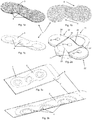
- the substrate 1 is substantially plane and comprises three conductive contact areas 4 with a first adhesive surface 2 configured for attaching the substrate to a medical device and a second adhesive surface 3 (opposite the first adhesive surface 2) configured for adhesive contact with skin such that adhesive and conductive contact is established between the medical device and the skin of a user of the medical device.
- the conductive contact areas 4 of the substrate 1 are not arranged in a line, which can be seen in fig.
- the conductive contact areas 4 are actually arranged such that the centres of the conductive contact areas 4 follow an arc of a circle and are also forming an isosceles triangle.
- the circumferential outline of the substrate 1 also substantially follows the bend of the conductive contact area which is visualized in fig. 6 .
- the circumferential outline of the substrate 1 further comprises two cut-outs 5, 5' which are also visualized in fig. 6 .
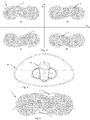
- Fig. 4a corresponds to fig. 1b .
- Fig. 4b shows the substrate of fig. 4a which has been reflected in the (vertical) Y-axis shown in fig. 4 .
- Such a reflection corresponds to a 180° rotation around an axis in the plane of the substrate 1 through the centre of the substrate 1 and parallel with the Y-axis.
- Fig. 4c shows the substrate of fig. 4a which has been reflected in the (horizontal) X-axis shown in fig. 4 .
- fig. 4d shows the substrate of fig. 4b reflected in the X-axis which also corresponds to the substrate of fig. 4c reflected in the Y-axis.
- Fig. 4d is also the result of a rotation of 180° of the substrate in fig. 4a around an axis perpendicular to the plane of the substrate.
- Fig. 5 shows the bottom of one embodiment of the presently disclosed medical device 21 when located in one embodiment of the presently disclosed charging station 41.
- the medical device 21 is also illustrated in fig. 2 .
- the medical device 21 comprises three electrodes 23, 23', 30 and protrusions 25, 25' and is configured to receive a disposable adhesive substrate on top of the electrodes and between the protrusions.
- the substrate 1 of fig. 4 is configured to match the medical device 21.
- Fig. 4 shows the four most likely orientations of the substrate 1 a user of the medical device 21 would choose between when facing the task of applying the substrate 1 to the medical device 21 because the conductive contact areas 4 in figs. 4a-d are arranged along the longitudinal extension of the electrodes 23, 23', 30 of the medical device 21.
- a disposable adhesive substrate can be provided with an asymmetric circumferential outline that helps a user with applying the substrate in the correct orientation and configuration on a medical device to ensure correct operation of the medical device.
- the substrate comprises at least three of said conductive contact areas wherein the circumferential outline is axially asymmetric along an axis perpendicular to a line connecting the centres of the outermost contact areas.
- the substrate comprises at least three of said conductive contact areas arranged in fixed isosceles triangular relationship one to another, wherein the circumferential outline of the substrate is axially asymmetric along an axis through the centre of the middle contact area which is perpendicular to a line connecting the centres of the outermost contact areas.
- the circumferential outline of the substrate is axially asymmetric along a long axis in the plane of the substrate and axially asymmetric along an axis perpendicular to the long axis in the plane of the substrate.
- the substrate may be configured to match one or more slot(s) and/or groove(s) on the medical device, preferably such that the substrate and the medical device have a one-to-one attachment correspondence.
- One way of providing a correspondence with a slot/groove is to provide one, two or more cut-outs in the circumferential outline of the substrate.
- Each cut-out may for example be shaped like an asymmetric wave pulse as exemplified in fig. 6 .
- Each cut-out may be rounded as also exemplified in the drawings.
- the cut-outs may be asymmetrically arranged along the circumferential outline of the substrate.
- the circumferential outline of the substrate may be substantially S-shaped as seen in the drawings.
- the shape of the cut-outs may be configured to match a slot / groove on the medical device, such that the substrate and the medical device has a one-to-one attachment correspondence.
- An exemplified shape of the cut-outs 5, 5' are visualized in fig. 6 where stippled lines indicate the circumferential outline of the substrate 1 without the cut-outs 5, 5'.
- the substrate comprises apertures.
- each of said contact areas at least partly encircles a corresponding aperture and the location and size of said apertures are preferably configured to match the location and size of the EMG electrodes of the medical device.
- the presently disclosed substrate may comprise at least three of such apertures arranged in a fixed spatial relationship one to another, such as arranged in a fixed triangular relationship one to another.
- the at least three apertures may be arranged such that the centres of said apertures are not on a line. Possibly the at least three apertures may be arranged such that the centres of said apertures lie on a line which is an arc of a circle having a radius of from 60-200 mm.
- centres of the apertures are arranged in a triangular arrangement in which the longest side of the triangle so defined is not more than 40 mm.
- Such arrangements of the apertures are exemplified and visualized in fig. 6 where a stippled line indicated the bending of the substrate 1 and the arrangement of the apertures.
- the presently disclosed substrate may further comprise two layers of removable protective sheet located on each plane side of the substrate as illustrated in fig. 3a-b , i.e. the substrate 1 is sandwiched between these protective sheets 9, 9'.
- the substrate 1 is stored with these sheets 9, 9' to protect and maintain the adhesiveness of the adhesive layers 2, 3.
- the protective sheets 9, 9' are preferably configured to be removed before use of the substrate 1 and may be arranged such that one sheet 9' is initially removed from the substrate exposing the adhesive side 2 of the substrate 1 that is attached to the medical device 21. After attachment to the medical device 21 the other protective sheet 9 can be removed from the substrate 1.
- Fig. 3 also illustrates a possible configuration of the conductive contact areas 4 which is best visualized in the cut-through illustration in fig. 3b showing the three conductive contact areas 4 encircling three apertures but are only exposed on the side 3 of the substrate 1 that is supposed to be attached to the skin of the user whereas the conductive contact areas 4 do not extend through the full thickness of the substrate 1.
- a medical device for monitoring muscular activity of an individual comprising a housing for accommodating a power source, a control unit and a processing unit, two wings bendably attached to opposite sides of the housing, and at least three electrodes, such as EMG electrodes, mounted and distributed on the housing and each wing such that the electrodes extend substantially in a plane across the housing and the wings.
- EMG electrodes e.g. for monitoring and treatment of bruxism
- the medical device is preferably configured such that the wings can flexibly and/or elastically adapt to 1) the local contour of the skin of the individual, 2) to movement of the individual, and/or to muscular flexion and/or abduction of the individual.
- the flexibility of the wings helps to provide a better contact with the muscles of the temple region, where the contour can be both concave and convex.
- the flexibility of the wings further helps to maintain the contact with the user during e.g. muscle contraction and in general when the user is moving.
- the presently disclosed medical device may be configured such that the two wings are elastically bendable in the plane of the electrodes.
- the two wings may be hingedly attached to the housing as exemplary illustrated in fig. 12 , where the upper electrode side of each wing is bendably attached to the upper side of the housing by means of a thinned connection formed by an elongated groove in the shell of the housing.
- the connection between the lower side of each wing (opposite the electrodes) and the housing may be formed by means of an edge of the wing which is adapted to slide on a corresponding edge of the housing.
- the presently disclosed medical device is preferably configured such that "in rest" the electrode are substantially arranged in the electrode plane, but when submitted to a pressure / force the wings can flex elastically from this plane.
- the medical device is preferably configured such that each of the two wings has a predefined maximal angular deflection from the electrode plane.
- the predefined maximal angular deflection may be more than ⁇ 5°, more preferably more than ⁇ 10°.
- the predefined maximal angular deflection may further preferably be less than ⁇ 30°, even more preferably less than ⁇ 20° and most preferably ⁇ 15°. As illustrated in figs.
- the wings 22, 22' can rotate around an axis defined by the innermost side 38 of the wall the housing 28 having a camming surface 34.
- the predefined maximal angular deflection of the wing 22 can upwardly be defined by the interface 35 abutting the inside wall 38 of the housing 28.
- the distance from the interface 35 to the inside wall 38 determines the amount by which the wing 22 can be bent upwards. Bending downwards is limited by the camming surface 34, i.e. the angular gap formed between the camming surface 34 and the underside 33 of wing 22 defines the maximum angle of downward bending of the wing 22.
- any un-skilled user can take advantage of the presently disclosed medical device and use it correctly. Correct use might imply that the user must apply a disposable adhesive substrate on the electrodes in order to provide adhesive and conductive contact with the skin of user. If a one-to-one correspondence is provided between a substrate and a medical device it can be ensured that the substrate is applied correctly each time.
- One way of providing this correspondence is to provide some kind of pattern or trace on the medical device wherein the substrate fits in a unique way. This may be provided by one or more protrusions on the housing of the medical device extending from the electrode plane as exemplary illustrated in the drawings, most noticeable in fig.
- the outline of the protrusion may be made asymmetric in order to match a corresponding asymmetric substrate.
- the maximal height of the protrusions is preferably less than the thickness of the corresponding substrate. E.g. the maximal height of the protrusions may be less than 1 mm.
- the outline of the protrusion(s) in the electrode plane can be shaped as an asymmetric wave.
- the protrusion(s) may furthermore be rounded, preferably both the contour and the outline of the protrusion(s) are rounded, to avoid sharp edges that may be uncomfortable for the user.
- two of said protrusions may be arranged to form a slot on the surface of the device.
- the protrusions are preferably arranged asymmetrically.
- the presently disclosed medical device is preferably configured to receive a disposable adhesive substrate in the electrode plane on the surface of the housing, wherein the substrate is configured to form an adhesive bond between the medical device and the skin of the individual and configured to form a conductive connection between the electrodes and the skin of the user.
- the medical device may be configured to receive a disposable adhesive substrate in a one-to-one correspondence on the surface of the housing in the electrode plane.
- the medical device may be configured to receive a disposable adhesive substrate in the abovementioned slot.
- the housing and the wings are at least partly manufactured in mouldable plastic and wherein the electrodes and terminals connecting the electrodes to the control unit are cast into and/or embedded into moulded plastic in the housing and the wings.
- An example of this is illustrated in figs. 9 , 12c and 12d where the electrode terminals 30', 32 and 32' are embedded into the housing and the wings.
- the presently disclosed medical device is configured such that the electrical power source can be wirelessly charged.
- the medical device is preferably also configured for storing data corresponding to measured and/or processed signals from muscular activity and configured for exchanging data with a terminal, e.g. the herein disclosed charging station.
- the data exchange is preferably wireless, e.g. by means of infrared communication between medical device and terminal / charging station.
- the medical device comprises two hollow pipes embedded in the housing and an infrared transmitter and an infrared receiver mounted in the housing, each of said IR units located in the housing at the end of one of said hollow pipes extending from the IR units to the shell of the housing, whereby said two-way infrared communication is provided via said hollow pipes.
- the hollow pipes thereby function as a sort of waveguide for the IR light. This is exemplified and illustrated in fig. 10 and described in further detail below.
- the presently disclosed medical device is configured for receiving and monitoring electrical signals via said electrodes and/or providing electrical stimulation to said individual via said electrodes.
- the medical device is configured for receiving and monitoring electrical signals via said electrodes, and wherein the processing unit is configured for processing the received signals in order to detect said bruxism, and wherein the medical device is configured to generate a feedback signal in response to said detection of bruxism, the feedback in the form of electrical stimulation provided via said electrodes to a user of the device.
- Detection of bruxism can be provided automatically as disclosed in pending application PCT/EP2015/060091 filed 07.05.2015 and entitled "Automatic detection of teeth clenching and/or teeth grinding”. This application is hereby incorporated by reference in its entirety.
- a charging station for a wireless battery driven medical device comprising a housing with an upper cover, the upper cover having a recess shaped to hold the medical device in a one-to-one correspondence.
- An exemplary charging station is illustrated in the drawings, in particular figs. 5 , 7 , 10 , 13 and 14 .
- the contour of the recess may be at least partly rounded such that the recess is configured to match a rounded medical device, e.g. the medical device as herein disclosed.
- the contour of the recess is at least partly rounded such that a rounded medical device can slide into the recess.
- the contour of the recess is at least partly bowl shaped, and/or at least partly ellipsoid as exemplified in fig. 13 .
- the presently disclosed charging station is configured such that when the medical device is located in the recess the medical device can be slit out of the recess by pushing down on a predefined first area of the surface of the medical device.
- the charging station may be configured such that the medical device is securely located in the charger (like a bumblebee in a nest) but also such that the medical device can be picked up easily by pushing on a predefined part of the device. This is exemplified by the big black arrow in fig. 7d .
- the charging station may be configured such that when the medical device is located in the recess the medical device is fixed in the recess when pushing down on a predefined second area of the surface of the medical device, as exemplified by the big black arrow in fig. 7b .
- This feature may be utilized during attachment of a disposable adhesive substrate on the medical device.
- This fixing in the recess may be provided by means of a protrusion on the upper cover of the charging station, a protrusion which may be covering, extending and/or protruding over at least a part of the recess, preferably such that when the medical device is located in the recess the protrusion is covering at least a part of the medical device.
- the charging station may be configured such that when pushing down on the second area of the surface of the medical device, an opposite side of the surface of the medical device engages with the protrusion such that the medical device is fixed in the recess, as exemplified by the protrusion 46 in fig. 7b .
- the recess of the charging station may be configured such that when the medical device is located in the recess the upper side of the medical device is substantially level with the upper side of the cover.
- a further advantage of a recess in the charging station for a corresponding medical device is that it provides the option of arranging an induction coil around the recess such that wireless charging of the medical device can be enable when the device is located in the recess.
- the housing of the charging station preferably also comprises an induction coil surrounding the recess and configured such that the medical device can be wirelessly charged when located in the recess.
- the presently disclosed charging station may further be configured for exchanging data wirelessly with the medical device. With the recess in the housing it can be ensured that the medical device is always arranged appropriately and in the correct configuration each time. This can be utilized for using infrared communication for the mutual data exchange between medical device and charging station, because IR communication usually requires a correct line of sight between transmitter and receiver.
- the presently disclosed charging station comprises an assembly of visual signalling units, such as LEDs, located in the housing and configured to indicate 1) the status of charging the battery of a medical device located in the recess, and/or 2) the status of data exchange with between charging station and a medical device located in the recess.
- the assembly of visual signalling units may be configured to be visible on and/or through the upper cover when indicating the charging status and/or the data exchange status. This is exemplified in fig. 14 where LEDs 48 are located at a circuit board of the charging station. Hollow pipes 48' leads to the upper cover 49; the upper surface of upper cover 49 is however unbroken. But light from the LEDs 48 can however penetrate the upper cover such that the LEDs can function as visual signalling units.
- the assembly of visual signalling units may furthermore be configured such that the signalling units are substantially invisible and/or inactive after a predefined period of time of activation of the signalling units and/or after a predefined period of time of inactivation of the charging station. If the medical device is used for monitoring and treatment of nocturnal bruxism the charging station may well be located in the bedroom. Hence, with an automatic lights-off functionality the charging station is not lighting up the bedroom during the night.
- the charging station may further comprise a touch sensitive area, such as a capacitive touch sensitive area, located on the upper cover and configured such that the assembly of visual signalling units indicates the charging status and/or the data exchange status for a predefined period of time when the touch sensitive area is activated. This provides the option of requesting e.g. charging status even if the signalling units have turned off.
- the housing of the presently disclosed charging station comprises a non-slip bottom surface, preferably configured to provide a slip-resistant contact with a supporting surface, i.e. in order to provide a solid and sturdy support for the medical device that does not move when the device is placed in the charging station.
- the housing may further comprise a weight plate, preferably configured to increase the stability of the charging station when located on a supporting surface.
- the presently disclosed charging station may further be configured to exchange data with a computing device, such as a smartphone, personal computer, etc.
- the data exchange with a computing device may be wireless, such by means of Bluetooth communication.
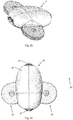
- FIG. 2a An example of the presently disclosed medical device 21 is illustrated in fig. 2a showing a perspective bottom view of the device 21. It is the same exemplary medical device that is illustrated in all the drawings, in particular figs. 2b, 2c , 5 , 7b, 7d , 8, 9, 10, 11 , 12a-d and 14 , and the numbering used is consistent in all figures.
- the medical device comprises two wings, right wing 22 and left wing 22' as illustrated in the top view in fig. 2c that are hingedly connected to the housing 28.
- a centre EMG electrode 30 and an EMG electrode 23, 23' on each wing provides a total of three EMG electrodes that are protruding slightly from the electrode plane 24, whereon a disposable adhesive asymmetric substrate 1 can be applied.
- Two push buttons 27, 27 are provided at opposite ends of the housing, the front button 27' and the back button 27.
- One of the push buttons is used to increase the stimulus level provided to the user upon detection of bruxism, the other push button is used to decrease this stimulus level.
- These are the only controls available to the user on the device itself and these are sufficient to control the device 21 - many other features are automatic, e.g. auto start-stop, automatic adjustment of the background / noise level and automatic adjustment of the threshold level of bruxism for providing a stimulus signal.
- Additional controls and input settings can be provided and controlled via a computing device, such as a smartphone, which can be arranged to communicate with the device 21 via the charging station 41, e.g. by means of software, e.g. an App, running on the computing device.
- the bottom side of the housing 28 of the medical device 21 protrudes slightly from the electrode plane 24 and two protrusions 25, 25' extends into the electrode plane 24 such that only a substrate with the outline as the substrate 1 in fig. 1 can be applied to the electrode plane 24 in the slot / groove / trace defined between the protrusions 25, 25'.
- Figs. 12c-d show different cut-through front view illustrations of the medical device 21.
- the battery 29 is visible in the housing 28.
- the wings 22, 22' are hingedly attached to the housing 28.
- the upper electrode side of each wing 22, 22' is bendably attached to the upper side of the housing by means of a thinned connection formed by an elongated groove 31, 31' in the shell of the housing 28.
- the housing 28 has two camming surfaces 34, 34' to allow downwards bending of the wings 22, 22'.
- the interfaces 36, 36' of the undersides 33, 33' of wings 22, 22' constitute the points of contact during bending of the wings 22, 22'.
- the wings 22, 22' are bendable up and down, and if e.g.
- Bending the wing 22 downwards is limited by the camming surface 34, i.e. the angular gap formed between the camming surface 34 and the underside 33 of wing 22 defines the maximum angle of downward bending of the wing 22, because when the wing 22 is bended downwards camming surface 34 will eventually abut the inner underside 33 of the wing 22 preventing the wing 22 from bending further downward.
- the same arrangement determining the maximum bending angles is provided for the left wing 22'.
- the wings 22, 22' are able to bend approx. 15° upwards and downwards, i.e. a maximum deflection of, in total, 30°.
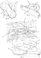
- FIG. 7a An example of the presently disclosed charging station 41 is illustrated in fig. 7a showing a perspective top view of the device 41. It is the same exemplary charging station that is at least partly illustrated in figs. 5 , 7a-d , 10 , 13a-c and 14 .
- This particular charging station 41 is configured to match (and charge) the illustrated medical device 21.
- the charging station 41 comprises a housing with an upper cover 42, the upper cover 42 having a recess 44 shaped to hold the medical device 21 in a one-to-one correspondence.
- the contour of the recess 44 is at least partly rounded such that the recess 44 is configured to match a medical device 21 with a rounded upper surface of the housing 28.
- the medical device 21 is located in the recess (nest) and a substrate 1 has been applied to the electrode surface of the device 21.
- the rounded surfaces of the device 21 and the recess 44 provides for the device sliding out of the recess 44 as also indicated in fig. 7d .
- the recess 44 in the housing provides for an elegant integration of the device 21 during charging but also for an easy removal of the device 21 by simply sliding it out of the recess 44.
- Fig. 7c shows the charging station 41 without the upper cover 42.
- the lower cover 45 is now visible and visible is also the outline / edge 43 of the recess and the trace 37 for an induction coil such that wireless charging of the medical device 21 can be provided.
- the charging station 41 has been disassembled further in fig. 13a-b showing the circuit board 46. It can be seen that the recess 44 is attached directly to the circuit board by means of screws 47.
- the trace 37 for the induction coil (not shown) is seen more clearly in fig. 13c showing a close-up of the recess (nest) 44.
- the cut-through illustration in fig. 14 shows three hollow pipes 48' in the upper cover 42 such that three LEDs 48 on the circuit board 46 are visible through the upper cover 42, approx. at the position indicated by arrow 49.
- FIG. 10 Another cut-through illustration is shown in fig. 10 where the device 21 is located in the charger 41.
- Two IR communication units 51, 51' are located in the charging station 41 and two IR communication units 54, 54' are located in the device 21 providing a total of four IR units.
- the IR units are paired and facing each other providing a line of sight between a transmitter in the charging station 41 and a receiver in the device 21, and between a receiver in the charging station 41 and a transmitter in the device 21.
- This line of sight vision is provided through hollow tubes / pipes 52, 52', 53, 53'.
Landscapes
- Health & Medical Sciences (AREA)
- Life Sciences & Earth Sciences (AREA)
- Surgery (AREA)
- Public Health (AREA)
- Pathology (AREA)
- Engineering & Computer Science (AREA)
- Biomedical Technology (AREA)
- Heart & Thoracic Surgery (AREA)
- Medical Informatics (AREA)
- Molecular Biology (AREA)
- Physics & Mathematics (AREA)
- Animal Behavior & Ethology (AREA)
- General Health & Medical Sciences (AREA)
- Biophysics (AREA)
- Veterinary Medicine (AREA)
- Physical Education & Sports Medicine (AREA)
- Dentistry (AREA)
- Oral & Maxillofacial Surgery (AREA)
- Orthopedic Medicine & Surgery (AREA)
- Rheumatology (AREA)
- Electrotherapy Devices (AREA)
- Measurement And Recording Of Electrical Phenomena And Electrical Characteristics Of The Living Body (AREA)
- Orthopedics, Nursing, And Contraception (AREA)
Claims (13)
- Wegwerfbares Klebstoffsubstrat (1), das dazu ausgelegt ist, an einer medizinischen Vorrichtung (21) mit EMG-Elektroden (23, 23', 30) angeordnet zu werden, wobei das Substrat (1) Folgendes umfasst:- eine erste Klebeschicht (2) auf einer ersten ebenen Seite des Substrats (1), die zum Anbringen des Substrats (1) an der medizinischen Vorrichtung (21) konfiguriert ist,- eine zweite Klebeschicht (3) auf einer zweiten ebenen Seite des Substrats (1), die zum Anbringen des Substrats (1) an der Haut eines Benutzers der medizinischen Vorrichtung (21) konfiguriert ist, und- leitfähige Kontaktbereiche (4), die zum Bereitstellen einer elektrischen Verbindung zwischen den EMG-Elektroden (23, 23', 30) und der Haut eines Benutzers der medizinischen Vorrichtung (21) konfiguriert sind,dadurch gekennzeichnet, dass die Umfangskontur des Substrats (1) um beliebige zwei senkrechte Rotationsachsen durch den Mittelpunkt des Substrats (1) und in der Ebene des Substrats (1) rotationssymmetrisch ist.
- Substrat (1) nach Anspruch 1, wobei die Umfangskontur des Substrats (1) um jede senkrechte Rotationsachse in der Ebene des Substrats (1) asymmetrisch ist.
- Substrat (1) nach einem der vorhergehenden Ansprüche, wobei die Umfangskontur des Substrats (1) ferner um eine zu der Ebene des Substrats (1) senkrechte Rotationsachse asymmetrisch ist.
- Substrat (1) nach einem der vorhergehenden Ansprüche, umfassend mindestens drei der leitfähigen Kontaktbereiche (4), wobei die Umfangskontur entlang einer Achse axial asymmetrisch ist, die zu einer Linie senkrecht ist, welche die Mittelpunkte der äußersten Kontaktbereiche verbindet.
- Substrat (1) nach einem der vorhergehenden Ansprüche, umfassend mindestens drei der leitfähigen Kontaktbereiche (4), die in einer festen gleichschenkligen Dreiecksbeziehung zueinander angeordnet sind, wobei die Umfangskontur des Substrats (1) entlang einer Achse durch den Mittelpunkt des mittleren Kontaktbereichs axial asymmetrisch ist, der zu einer Linie senkrecht ist, welche die Mittelpunkt der äußersten Kontaktbereiche (4) verbindet.
- Substrat (1) nach einem der vorhergehenden Ansprüche, ferner umfassend zwei rundliche Ausschnitte (5, 5') in der Umfangskontur des Substrats (1).
- Substrat nach Anspruch 6, wobei die Ausschnitte (5, 5') asymmetrisch entlang der Umfangskontur des Substrats (1) angeordnet sind.
- Substrat (1) nach einem der vorhergehenden Ansprüche 6-7, wobei die Ausschnitte (5, 5') in der Kontur wie ein asymmetrischer Wellenimpuls geformt sind.
- Substrat (1) nach einem der vorhergehenden Ansprüche, wobei die Umfangskontur des Substrats (1) im Wesentlichen S-förmig ist.
- Substrat (1) nach einem der vorhergehenden Ansprüche, ferner umfassend mindestens drei Öffnungen, die in einer festen Dreiecksbeziehung zueinander angeordnet sind.
- Substrat (1) nach Anspruch 10, wobei jeder der Kontaktbereiche (4) zumindest teilweise eine entsprechende Öffnung umgibt.
- Substrat (1) nach einem der vorhergehenden Ansprüche, das dazu konfiguriert ist, eine Klebeverbindung zwischen der medizinischen Vorrichtung (21) und der Haut des Benutzers zu bilden, und die dazu konfiguriert ist, eine leitende Verbindung zwischen den EMG-Elektroden (23, 23', 30) und der Haut des Benutzers zu bilden.
- Substrat (1) nach einem der vorhergehenden Ansprüche, wobei das Substrat (1) flexibel und/oder biegbar ist.
Applications Claiming Priority (2)
| Application Number | Priority Date | Filing Date | Title |
|---|---|---|---|
| EP15174601 | 2015-06-30 | ||
| PCT/EP2016/065133 WO2017001470A1 (en) | 2015-06-30 | 2016-06-29 | Disposable adhesive substrate adapted to be arranged on a medical device |
Publications (2)
| Publication Number | Publication Date |
|---|---|
| EP3316775A1 EP3316775A1 (de) | 2018-05-09 |
| EP3316775B1 true EP3316775B1 (de) | 2019-11-20 |
Family
ID=53498893
Family Applications (1)
| Application Number | Title | Priority Date | Filing Date |
|---|---|---|---|
| EP16734293.0A Active EP3316775B1 (de) | 2015-06-30 | 2016-06-29 | Wegwerfbares klebstoffsubstrat zur anordnung an einer medizinischen vorrichtung |
Country Status (12)
| Country | Link |
|---|---|
| US (1) | US10779749B2 (de) |
| EP (1) | EP3316775B1 (de) |
| JP (1) | JP6840924B2 (de) |
| CN (1) | CN107847179B (de) |
| AR (1) | AR105205A1 (de) |
| BR (1) | BR112017028236B1 (de) |
| CA (1) | CA2989731C (de) |
| DK (1) | DK3316775T3 (de) |
| ES (1) | ES2765195T3 (de) |
| RU (1) | RU2719953C2 (de) |
| TW (2) | TWI705796B (de) |
| WO (1) | WO2017001470A1 (de) |
Families Citing this family (16)
| Publication number | Priority date | Publication date | Assignee | Title |
|---|---|---|---|---|
| USD849955S1 (en) * | 2015-02-12 | 2019-05-28 | Sunstar Suisse Sa | Medical instrument with sensor for treatment of bruxism |
| KR101808605B1 (ko) * | 2016-12-22 | 2018-01-18 | 김재범 | 전파 전달이 가능하거나 방열특성을 가지는 전도층이 코팅된 비전도성 프레임 |
| USD862715S1 (en) * | 2017-06-06 | 2019-10-08 | Jiangsu Alphay Medical Device Co., Ltd. | Health-regain device |
| KR20200144550A (ko) * | 2018-03-20 | 2020-12-29 | 그래프웨어 테크놀로지스 인크. | 교체가능 센서 시스템들 및 방법들 |
| US11612344B2 (en) * | 2018-11-02 | 2023-03-28 | Biocircuit Technologies, Inc. | Electrode-based systems and devices for interfacing with biological tissue and related methods |
| JP6591097B1 (ja) * | 2019-01-09 | 2019-10-16 | 株式会社レーベン | 粘着シート |
| US11484265B2 (en) | 2019-06-06 | 2022-11-01 | Biointellisense, Inc. | Adhesive device |
| CN112716500A (zh) * | 2019-10-28 | 2021-04-30 | 苏州匡迪医疗科技有限公司 | 一种便携式心电图机 |
| US11583218B2 (en) * | 2019-11-20 | 2023-02-21 | Advancer Technologies, Llc | EMG device |
| USD1015545S1 (en) * | 2019-11-20 | 2024-02-20 | Advancer Technologies, Llc | Electromyography device |
| US12589021B2 (en) | 2019-12-28 | 2026-03-31 | Morari, Inc. | Apparatus and method of treating an approaching physiological event and increasing an intensity of the event |
| US11963901B2 (en) * | 2019-12-28 | 2024-04-23 | Jeffrey Bennett | Apparatus and method of treating an approaching physiological event and increasing an intensity of the event |
| AU2021322280B2 (en) * | 2020-08-06 | 2025-02-06 | Irhythm Technologies, Inc. | Adhesive physiological monitoring device |
| WO2026014016A1 (ja) * | 2024-07-08 | 2026-01-15 | サンスター スイス エスエー | ブラキシズムマネジメント法に対する適応性を予測し、当該マネジメント法の適用範囲を示す情報処理システム、情報処理方法、および制御プログラム |
| JP7782082B1 (ja) * | 2025-01-18 | 2025-12-08 | ピー ボー | 取り外し可能な電極パッチユニットを備えた生理的信号モニタリング装置 |
| CN120679081B (zh) * | 2025-08-18 | 2026-01-27 | 长春爱康医疗器械股份有限公司 | 一种集成中频治疗仪及电极贴片 |
Citations (1)
| Publication number | Priority date | Publication date | Assignee | Title |
|---|---|---|---|---|
| WO2016138176A1 (en) * | 2015-02-24 | 2016-09-01 | Elira Therapeutics Llc | Systems and methods for enabling appetite modulation and/or improving dietary compliance using an electro-dermal patch |
Family Cites Families (20)
| Publication number | Priority date | Publication date | Assignee | Title |
|---|---|---|---|---|
| US6385473B1 (en) * | 1999-04-15 | 2002-05-07 | Nexan Limited | Physiological sensor device |
| US6602201B1 (en) | 2000-07-10 | 2003-08-05 | Cardiodynamics International Corporation | Apparatus and method for determining cardiac output in a living subject |
| US20100222734A1 (en) * | 2005-09-01 | 2010-09-02 | Dalia Jayes | Double-sided patch |
| US8214007B2 (en) * | 2006-11-01 | 2012-07-03 | Welch Allyn, Inc. | Body worn physiological sensor device having a disposable electrode module |
| CN201073301Y (zh) * | 2007-06-15 | 2008-06-18 | 张卫红 | 一次性医用蝶形电极贴 |
| EP2200510B1 (de) * | 2007-09-21 | 2011-12-28 | Medotech A/S | Elektrodenanordnungen und bruxismusüberwachungsgerät |
| CA2794409C (en) * | 2010-04-08 | 2019-03-12 | Med Storm Innovation As | Disposable electrode patch |
| US8690800B2 (en) * | 2010-05-18 | 2014-04-08 | Erik Lillydahl | Systems and methods for reducing subconscious neuromuscular tension including bruxism |
| US20120089000A1 (en) * | 2010-10-08 | 2012-04-12 | Jon Mikalson Bishay | Ambulatory Electrocardiographic Monitor For Providing Ease Of Use In Women And Method Of Use |
| CN201929957U (zh) * | 2011-01-14 | 2011-08-17 | 魏邦敏 | 一种烧伤植皮用面积计算贴 |
| IL218146A (en) | 2012-02-16 | 2016-02-29 | New N I Medical (2011) Ltd | Biomedical electrode assembly |
| WO2013181508A1 (en) | 2012-05-31 | 2013-12-05 | Zoll Medical Corporation | Long term wear multifunction biomedical electrode |
| CN104427933A (zh) * | 2012-06-29 | 2015-03-18 | 盛势达瑞士股份公司 | 凝胶垫分配器 |
| EP2892422B1 (de) * | 2012-09-04 | 2022-04-06 | LKC Technologies, Inc. | Elektrodenmatrix und messverfahren unter verwendung derselben |
| WO2014052884A1 (en) * | 2012-09-28 | 2014-04-03 | Cardiac Insight, Inc. | Flexible, lightweight physiological monitor |
| JP2015534495A (ja) * | 2012-10-12 | 2015-12-03 | デルタ、ダンスク・エレクトリニク、リス・オ・アクスティクDelta,Dansk Elektronik,Lys Og Akustik | 監視デバイス |
| KR20140004168U (ko) | 2012-12-28 | 2014-07-08 | 주식회사 씨유메디칼시스템 | 심전도 측정용 전극패드 |
| KR20140088390A (ko) * | 2013-01-02 | 2014-07-10 | (주) 태웅메디칼 | 생체신호 측정용 패치형 전극 |
| SG11201509901VA (en) * | 2013-06-06 | 2016-01-28 | Tricord Holdings L L C | Modular physiologic monitoring systems, kits, and methods |
| JP6134865B2 (ja) | 2013-09-16 | 2017-05-24 | コーニンクレッカ フィリップス エヌ ヴェKoninklijke Philips N.V. | 生物医学的電極パッド |
-
2016
- 2016-06-29 US US15/740,515 patent/US10779749B2/en active Active
- 2016-06-29 ES ES16734293T patent/ES2765195T3/es active Active
- 2016-06-29 JP JP2017566327A patent/JP6840924B2/ja active Active
- 2016-06-29 CA CA2989731A patent/CA2989731C/en active Active
- 2016-06-29 RU RU2018102711A patent/RU2719953C2/ru active
- 2016-06-29 CN CN201680039310.1A patent/CN107847179B/zh active Active
- 2016-06-29 TW TW106125733A patent/TWI705796B/zh active
- 2016-06-29 WO PCT/EP2016/065133 patent/WO2017001470A1/en not_active Ceased
- 2016-06-29 TW TW105120650A patent/TWI603713B/zh active
- 2016-06-29 EP EP16734293.0A patent/EP3316775B1/de active Active
- 2016-06-29 BR BR112017028236-4A patent/BR112017028236B1/pt active IP Right Grant
- 2016-06-29 DK DK16734293.0T patent/DK3316775T3/da active
- 2016-06-30 AR ARP160101988A patent/AR105205A1/es active IP Right Grant
Patent Citations (1)
| Publication number | Priority date | Publication date | Assignee | Title |
|---|---|---|---|---|
| WO2016138176A1 (en) * | 2015-02-24 | 2016-09-01 | Elira Therapeutics Llc | Systems and methods for enabling appetite modulation and/or improving dietary compliance using an electro-dermal patch |
Also Published As
| Publication number | Publication date |
|---|---|
| DK3316775T3 (da) | 2020-03-02 |
| RU2018102711A3 (de) | 2019-11-11 |
| EP3316775A1 (de) | 2018-05-09 |
| US20180184939A1 (en) | 2018-07-05 |
| CA2989731A1 (en) | 2017-01-05 |
| JP6840924B2 (ja) | 2021-03-10 |
| RU2719953C2 (ru) | 2020-04-23 |
| US10779749B2 (en) | 2020-09-22 |
| TWI603713B (zh) | 2017-11-01 |
| TW201707649A (zh) | 2017-03-01 |
| CN107847179A (zh) | 2018-03-27 |
| TW201808225A (zh) | 2018-03-16 |
| BR112017028236B1 (pt) | 2022-11-16 |
| TWI705796B (zh) | 2020-10-01 |
| AR105205A1 (es) | 2017-09-13 |
| RU2018102711A (ru) | 2019-07-31 |
| WO2017001470A1 (en) | 2017-01-05 |
| JP2018526051A (ja) | 2018-09-13 |
| CA2989731C (en) | 2024-06-11 |
| CN107847179B (zh) | 2021-07-23 |
| BR112017028236A2 (pt) | 2018-09-04 |
| ES2765195T3 (es) | 2020-06-08 |
Similar Documents
| Publication | Publication Date | Title |
|---|---|---|
| CA2989731C (en) | Disposable adhesive substrate adapted to be arranged on a medical device | |
| US7722249B2 (en) | Body-temperature measuring device and body-temperature measuring system having the device | |
| CN109328088B (zh) | 可植入医疗设备的外部充电器 | |
| US9242091B2 (en) | Systems and methods for therapeutic electrical stimulation | |
| US8560040B2 (en) | Shielded biomedical electrode patch | |
| EP2164389B1 (de) | Abgeschirmte biomedizinische elektrodenfläche | |
| AU2014203618B2 (en) | Systems and methods for therapeutic electrical stimulation | |
| CN108853724B (zh) | 神经电刺激装置 | |
| CN115276254B (zh) | 用于向可植入医疗设备(imd)无线地提供能量的外部充电器 | |
| WO2008033669A3 (en) | Moisture resistant electrode with edge protection | |
| CN105457158A (zh) | 可佩戴的经皮神经刺激器 | |
| JP3227463U (ja) | 電気刺激装置の加熱構造 | |
| CN207493061U (zh) | 神经电刺激装置 | |
| JP2019155009A (ja) | 電極パッド | |
| JP7199276B2 (ja) | 筋肉電気刺激装置 | |
| JP6868153B2 (ja) | 通信装置 | |
| KR20190080572A (ko) | 스마트 근전도감지기의 접촉면 증대구조 |
Legal Events
| Date | Code | Title | Description |
|---|---|---|---|
| STAA | Information on the status of an ep patent application or granted ep patent |
Free format text: STATUS: THE INTERNATIONAL PUBLICATION HAS BEEN MADE |
|
| PUAI | Public reference made under article 153(3) epc to a published international application that has entered the european phase |
Free format text: ORIGINAL CODE: 0009012 |
|
| STAA | Information on the status of an ep patent application or granted ep patent |
Free format text: STATUS: REQUEST FOR EXAMINATION WAS MADE |
|
| 17P | Request for examination filed |
Effective date: 20180130 |
|
| AK | Designated contracting states |
Kind code of ref document: A1 Designated state(s): AL AT BE BG CH CY CZ DE DK EE ES FI FR GB GR HR HU IE IS IT LI LT LU LV MC MK MT NL NO PL PT RO RS SE SI SK SM TR |
|
| AX | Request for extension of the european patent |
Extension state: BA ME |
|
| DAV | Request for validation of the european patent (deleted) | ||
| DAX | Request for extension of the european patent (deleted) | ||
| RIC1 | Information provided on ipc code assigned before grant |
Ipc: A61B 5/0492 20060101AFI20190221BHEP Ipc: A61N 1/36 20060101ALN20190221BHEP Ipc: A61N 1/04 20060101ALN20190221BHEP Ipc: A61B 5/00 20060101ALN20190221BHEP |
|
| GRAP | Despatch of communication of intention to grant a patent |
Free format text: ORIGINAL CODE: EPIDOSNIGR1 |
|
| STAA | Information on the status of an ep patent application or granted ep patent |
Free format text: STATUS: GRANT OF PATENT IS INTENDED |
|
| INTG | Intention to grant announced |
Effective date: 20190429 |
|
| GRAJ | Information related to disapproval of communication of intention to grant by the applicant or resumption of examination proceedings by the epo deleted |
Free format text: ORIGINAL CODE: EPIDOSDIGR1 |
|
| STAA | Information on the status of an ep patent application or granted ep patent |
Free format text: STATUS: REQUEST FOR EXAMINATION WAS MADE |
|
| INTC | Intention to grant announced (deleted) | ||
| GRAR | Information related to intention to grant a patent recorded |
Free format text: ORIGINAL CODE: EPIDOSNIGR71 |
|
| GRAS | Grant fee paid |
Free format text: ORIGINAL CODE: EPIDOSNIGR3 |
|
| STAA | Information on the status of an ep patent application or granted ep patent |
Free format text: STATUS: GRANT OF PATENT IS INTENDED |
|
| GRAA | (expected) grant |
Free format text: ORIGINAL CODE: 0009210 |
|
| STAA | Information on the status of an ep patent application or granted ep patent |
Free format text: STATUS: THE PATENT HAS BEEN GRANTED |
|
| RIC1 | Information provided on ipc code assigned before grant |
Ipc: A61N 1/36 20060101ALN20190918BHEP Ipc: A61N 1/04 20060101ALN20190918BHEP Ipc: A61B 5/0492 20060101AFI20190918BHEP Ipc: A61B 5/00 20060101ALN20190918BHEP |
|
| AK | Designated contracting states |
Kind code of ref document: B1 Designated state(s): AL AT BE BG CH CY CZ DE DK EE ES FI FR GB GR HR HU IE IS IT LI LT LU LV MC MK MT NL NO PL PT RO RS SE SI SK SM TR |
|
| INTG | Intention to grant announced |
Effective date: 20191011 |
|
| REG | Reference to a national code |
Ref country code: GB Ref legal event code: FG4D |
|
| REG | Reference to a national code |
Ref country code: CH Ref legal event code: EP |
|
| REG | Reference to a national code |
Ref country code: IE Ref legal event code: FG4D |
|
| REG | Reference to a national code |
Ref country code: DE Ref legal event code: R096 Ref document number: 602016024688 Country of ref document: DE |
|
| REG | Reference to a national code |
Ref country code: AT Ref legal event code: REF Ref document number: 1203224 Country of ref document: AT Kind code of ref document: T Effective date: 20191215 |
|
| REG | Reference to a national code |
Ref country code: CH Ref legal event code: NV Representative=s name: STOLMAR AND PARTNER INTELLECTUAL PROPERTY S.A., CH |
|
| REG | Reference to a national code |
Ref country code: NL Ref legal event code: FP |
|
| REG | Reference to a national code |
Ref country code: DK Ref legal event code: T3 Effective date: 20200225 |
|
| REG | Reference to a national code |
Ref country code: SE Ref legal event code: TRGR |
|
| REG | Reference to a national code |
Ref country code: LT Ref legal event code: MG4D |
|
| PG25 | Lapsed in a contracting state [announced via postgrant information from national office to epo] |
Ref country code: GR Free format text: LAPSE BECAUSE OF FAILURE TO SUBMIT A TRANSLATION OF THE DESCRIPTION OR TO PAY THE FEE WITHIN THE PRESCRIBED TIME-LIMIT Effective date: 20200221 Ref country code: NO Free format text: LAPSE BECAUSE OF FAILURE TO SUBMIT A TRANSLATION OF THE DESCRIPTION OR TO PAY THE FEE WITHIN THE PRESCRIBED TIME-LIMIT Effective date: 20200220 Ref country code: LT Free format text: LAPSE BECAUSE OF FAILURE TO SUBMIT A TRANSLATION OF THE DESCRIPTION OR TO PAY THE FEE WITHIN THE PRESCRIBED TIME-LIMIT Effective date: 20191120 Ref country code: FI Free format text: LAPSE BECAUSE OF FAILURE TO SUBMIT A TRANSLATION OF THE DESCRIPTION OR TO PAY THE FEE WITHIN THE PRESCRIBED TIME-LIMIT Effective date: 20191120 Ref country code: BG Free format text: LAPSE BECAUSE OF FAILURE TO SUBMIT A TRANSLATION OF THE DESCRIPTION OR TO PAY THE FEE WITHIN THE PRESCRIBED TIME-LIMIT Effective date: 20200220 Ref country code: LV Free format text: LAPSE BECAUSE OF FAILURE TO SUBMIT A TRANSLATION OF THE DESCRIPTION OR TO PAY THE FEE WITHIN THE PRESCRIBED TIME-LIMIT Effective date: 20191120 |
|
| PG25 | Lapsed in a contracting state [announced via postgrant information from national office to epo] |
Ref country code: RS Free format text: LAPSE BECAUSE OF FAILURE TO SUBMIT A TRANSLATION OF THE DESCRIPTION OR TO PAY THE FEE WITHIN THE PRESCRIBED TIME-LIMIT Effective date: 20191120 Ref country code: HR Free format text: LAPSE BECAUSE OF FAILURE TO SUBMIT A TRANSLATION OF THE DESCRIPTION OR TO PAY THE FEE WITHIN THE PRESCRIBED TIME-LIMIT Effective date: 20191120 Ref country code: IS Free format text: LAPSE BECAUSE OF FAILURE TO SUBMIT A TRANSLATION OF THE DESCRIPTION OR TO PAY THE FEE WITHIN THE PRESCRIBED TIME-LIMIT Effective date: 20200320 |
|
| REG | Reference to a national code |
Ref country code: ES Ref legal event code: FG2A Ref document number: 2765195 Country of ref document: ES Kind code of ref document: T3 Effective date: 20200608 |
|
| PG25 | Lapsed in a contracting state [announced via postgrant information from national office to epo] |
Ref country code: AL Free format text: LAPSE BECAUSE OF FAILURE TO SUBMIT A TRANSLATION OF THE DESCRIPTION OR TO PAY THE FEE WITHIN THE PRESCRIBED TIME-LIMIT Effective date: 20191120 |
|
| PG25 | Lapsed in a contracting state [announced via postgrant information from national office to epo] |
Ref country code: PT Free format text: LAPSE BECAUSE OF FAILURE TO SUBMIT A TRANSLATION OF THE DESCRIPTION OR TO PAY THE FEE WITHIN THE PRESCRIBED TIME-LIMIT Effective date: 20200412 Ref country code: EE Free format text: LAPSE BECAUSE OF FAILURE TO SUBMIT A TRANSLATION OF THE DESCRIPTION OR TO PAY THE FEE WITHIN THE PRESCRIBED TIME-LIMIT Effective date: 20191120 Ref country code: CZ Free format text: LAPSE BECAUSE OF FAILURE TO SUBMIT A TRANSLATION OF THE DESCRIPTION OR TO PAY THE FEE WITHIN THE PRESCRIBED TIME-LIMIT Effective date: 20191120 Ref country code: RO Free format text: LAPSE BECAUSE OF FAILURE TO SUBMIT A TRANSLATION OF THE DESCRIPTION OR TO PAY THE FEE WITHIN THE PRESCRIBED TIME-LIMIT Effective date: 20191120 |
|
| REG | Reference to a national code |
Ref country code: AT Ref legal event code: MK05 Ref document number: 1203224 Country of ref document: AT Kind code of ref document: T Effective date: 20191120 |
|
| REG | Reference to a national code |
Ref country code: DE Ref legal event code: R097 Ref document number: 602016024688 Country of ref document: DE |
|
| PG25 | Lapsed in a contracting state [announced via postgrant information from national office to epo] |
Ref country code: SK Free format text: LAPSE BECAUSE OF FAILURE TO SUBMIT A TRANSLATION OF THE DESCRIPTION OR TO PAY THE FEE WITHIN THE PRESCRIBED TIME-LIMIT Effective date: 20191120 Ref country code: SM Free format text: LAPSE BECAUSE OF FAILURE TO SUBMIT A TRANSLATION OF THE DESCRIPTION OR TO PAY THE FEE WITHIN THE PRESCRIBED TIME-LIMIT Effective date: 20191120 |
|
| PLBE | No opposition filed within time limit |
Free format text: ORIGINAL CODE: 0009261 |
|
| STAA | Information on the status of an ep patent application or granted ep patent |
Free format text: STATUS: NO OPPOSITION FILED WITHIN TIME LIMIT |
|
| 26N | No opposition filed |
Effective date: 20200821 |
|
| REG | Reference to a national code |
Ref country code: DE Ref legal event code: R079 Ref document number: 602016024688 Country of ref document: DE Free format text: PREVIOUS MAIN CLASS: A61B0005049200 Ipc: A61B0005296000 |
|
| PG25 | Lapsed in a contracting state [announced via postgrant information from national office to epo] |
Ref country code: AT Free format text: LAPSE BECAUSE OF FAILURE TO SUBMIT A TRANSLATION OF THE DESCRIPTION OR TO PAY THE FEE WITHIN THE PRESCRIBED TIME-LIMIT Effective date: 20191120 Ref country code: PL Free format text: LAPSE BECAUSE OF FAILURE TO SUBMIT A TRANSLATION OF THE DESCRIPTION OR TO PAY THE FEE WITHIN THE PRESCRIBED TIME-LIMIT Effective date: 20191120 Ref country code: SI Free format text: LAPSE BECAUSE OF FAILURE TO SUBMIT A TRANSLATION OF THE DESCRIPTION OR TO PAY THE FEE WITHIN THE PRESCRIBED TIME-LIMIT Effective date: 20191120 |
|
| PG25 | Lapsed in a contracting state [announced via postgrant information from national office to epo] |
Ref country code: MC Free format text: LAPSE BECAUSE OF FAILURE TO SUBMIT A TRANSLATION OF THE DESCRIPTION OR TO PAY THE FEE WITHIN THE PRESCRIBED TIME-LIMIT Effective date: 20191120 |
|
| PG25 | Lapsed in a contracting state [announced via postgrant information from national office to epo] |
Ref country code: LU Free format text: LAPSE BECAUSE OF NON-PAYMENT OF DUE FEES Effective date: 20200629 |
|
| REG | Reference to a national code |
Ref country code: BE Ref legal event code: MM Effective date: 20200630 |
|
| PG25 | Lapsed in a contracting state [announced via postgrant information from national office to epo] |
Ref country code: IE Free format text: LAPSE BECAUSE OF NON-PAYMENT OF DUE FEES Effective date: 20200629 |
|
| PG25 | Lapsed in a contracting state [announced via postgrant information from national office to epo] |
Ref country code: BE Free format text: LAPSE BECAUSE OF NON-PAYMENT OF DUE FEES Effective date: 20200630 |
|
| PG25 | Lapsed in a contracting state [announced via postgrant information from national office to epo] |
Ref country code: TR Free format text: LAPSE BECAUSE OF FAILURE TO SUBMIT A TRANSLATION OF THE DESCRIPTION OR TO PAY THE FEE WITHIN THE PRESCRIBED TIME-LIMIT Effective date: 20191120 Ref country code: MT Free format text: LAPSE BECAUSE OF FAILURE TO SUBMIT A TRANSLATION OF THE DESCRIPTION OR TO PAY THE FEE WITHIN THE PRESCRIBED TIME-LIMIT Effective date: 20191120 Ref country code: CY Free format text: LAPSE BECAUSE OF FAILURE TO SUBMIT A TRANSLATION OF THE DESCRIPTION OR TO PAY THE FEE WITHIN THE PRESCRIBED TIME-LIMIT Effective date: 20191120 |
|
| PG25 | Lapsed in a contracting state [announced via postgrant information from national office to epo] |
Ref country code: MK Free format text: LAPSE BECAUSE OF FAILURE TO SUBMIT A TRANSLATION OF THE DESCRIPTION OR TO PAY THE FEE WITHIN THE PRESCRIBED TIME-LIMIT Effective date: 20191120 |
|
| P01 | Opt-out of the competence of the unified patent court (upc) registered |
Effective date: 20230331 |
|
| PGFP | Annual fee paid to national office [announced via postgrant information from national office to epo] |
Ref country code: NL Payment date: 20250520 Year of fee payment: 10 |
|
| PGFP | Annual fee paid to national office [announced via postgrant information from national office to epo] |
Ref country code: DE Payment date: 20250520 Year of fee payment: 10 |
|
| PGFP | Annual fee paid to national office [announced via postgrant information from national office to epo] |
Ref country code: GB Payment date: 20250616 Year of fee payment: 10 Ref country code: DK Payment date: 20250624 Year of fee payment: 10 |
|
| PGFP | Annual fee paid to national office [announced via postgrant information from national office to epo] |
Ref country code: IT Payment date: 20250521 Year of fee payment: 10 |
|
| PGFP | Annual fee paid to national office [announced via postgrant information from national office to epo] |
Ref country code: FR Payment date: 20250616 Year of fee payment: 10 |
|
| PGFP | Annual fee paid to national office [announced via postgrant information from national office to epo] |
Ref country code: SE Payment date: 20250616 Year of fee payment: 10 |
|
| PGFP | Annual fee paid to national office [announced via postgrant information from national office to epo] |
Ref country code: ES Payment date: 20250708 Year of fee payment: 10 |
|
| PGFP | Annual fee paid to national office [announced via postgrant information from national office to epo] |
Ref country code: CH Payment date: 20250701 Year of fee payment: 10 |