EP3315879B1 - Auswerfer und kältekreislaufvorrichtung mit einem auswerfer - Google Patents
Auswerfer und kältekreislaufvorrichtung mit einem auswerfer Download PDFInfo
- Publication number
- EP3315879B1 EP3315879B1 EP17184724.7A EP17184724A EP3315879B1 EP 3315879 B1 EP3315879 B1 EP 3315879B1 EP 17184724 A EP17184724 A EP 17184724A EP 3315879 B1 EP3315879 B1 EP 3315879B1
- Authority
- EP
- European Patent Office
- Prior art keywords
- needle
- ejector
- drive
- refrigerant
- nozzle
- Prior art date
- Legal status (The legal status is an assumption and is not a legal conclusion. Google has not performed a legal analysis and makes no representation as to the accuracy of the status listed.)
- Not-in-force
Links
Images


Classifications
-
- F—MECHANICAL ENGINEERING; LIGHTING; HEATING; WEAPONS; BLASTING
- F25—REFRIGERATION OR COOLING; COMBINED HEATING AND REFRIGERATION SYSTEMS; HEAT PUMP SYSTEMS; MANUFACTURE OR STORAGE OF ICE; LIQUEFACTION SOLIDIFICATION OF GASES
- F25B—REFRIGERATION MACHINES, PLANTS OR SYSTEMS; COMBINED HEATING AND REFRIGERATION SYSTEMS; HEAT PUMP SYSTEMS
- F25B9/00—Compression machines, plants or systems, in which the refrigerant is air or other gas of low boiling point
- F25B9/08—Compression machines, plants or systems, in which the refrigerant is air or other gas of low boiling point using ejectors
-
- F—MECHANICAL ENGINEERING; LIGHTING; HEATING; WEAPONS; BLASTING
- F25—REFRIGERATION OR COOLING; COMBINED HEATING AND REFRIGERATION SYSTEMS; HEAT PUMP SYSTEMS; MANUFACTURE OR STORAGE OF ICE; LIQUEFACTION SOLIDIFICATION OF GASES
- F25B—REFRIGERATION MACHINES, PLANTS OR SYSTEMS; COMBINED HEATING AND REFRIGERATION SYSTEMS; HEAT PUMP SYSTEMS
- F25B41/00—Fluid-circulation arrangements
-
- F—MECHANICAL ENGINEERING; LIGHTING; HEATING; WEAPONS; BLASTING
- F25—REFRIGERATION OR COOLING; COMBINED HEATING AND REFRIGERATION SYSTEMS; HEAT PUMP SYSTEMS; MANUFACTURE OR STORAGE OF ICE; LIQUEFACTION SOLIDIFICATION OF GASES
- F25B—REFRIGERATION MACHINES, PLANTS OR SYSTEMS; COMBINED HEATING AND REFRIGERATION SYSTEMS; HEAT PUMP SYSTEMS
- F25B49/00—Arrangement or mounting of control or safety devices
- F25B49/02—Arrangement or mounting of control or safety devices for compression type machines, plants or systems
-
- B—PERFORMING OPERATIONS; TRANSPORTING
- B60—VEHICLES IN GENERAL
- B60H—ARRANGEMENTS OF HEATING, COOLING, VENTILATING OR OTHER AIR-TREATING DEVICES SPECIALLY ADAPTED FOR PASSENGER OR GOODS SPACES OF VEHICLES
- B60H1/00—Heating, cooling or ventilating devices
- B60H1/32—Cooling devices
- B60H2001/3286—Constructional features
- B60H2001/3298—Ejector-type refrigerant circuits
-
- F—MECHANICAL ENGINEERING; LIGHTING; HEATING; WEAPONS; BLASTING
- F04—POSITIVE - DISPLACEMENT MACHINES FOR LIQUIDS; PUMPS FOR LIQUIDS OR ELASTIC FLUIDS
- F04F—PUMPING OF FLUID BY DIRECT CONTACT OF ANOTHER FLUID OR BY USING INERTIA OF FLUID TO BE PUMPED; SIPHONS
- F04F5/00—Jet pumps, i.e. devices in which flow is induced by pressure drop caused by velocity of another fluid flow
- F04F5/44—Component parts, details, or accessories not provided for in, or of interest apart from, groups F04F5/02 - F04F5/42
- F04F5/46—Arrangements of nozzles
- F04F5/461—Adjustable nozzles
-
- F—MECHANICAL ENGINEERING; LIGHTING; HEATING; WEAPONS; BLASTING
- F04—POSITIVE - DISPLACEMENT MACHINES FOR LIQUIDS; PUMPS FOR LIQUIDS OR ELASTIC FLUIDS
- F04F—PUMPING OF FLUID BY DIRECT CONTACT OF ANOTHER FLUID OR BY USING INERTIA OF FLUID TO BE PUMPED; SIPHONS
- F04F5/00—Jet pumps, i.e. devices in which flow is induced by pressure drop caused by velocity of another fluid flow
- F04F5/44—Component parts, details, or accessories not provided for in, or of interest apart from, groups F04F5/02 - F04F5/42
- F04F5/46—Arrangements of nozzles
- F04F5/463—Arrangements of nozzles with provisions for mixing
-
- F—MECHANICAL ENGINEERING; LIGHTING; HEATING; WEAPONS; BLASTING
- F05—INDEXING SCHEMES RELATING TO ENGINES OR PUMPS IN VARIOUS SUBCLASSES OF CLASSES F01-F04
- F05D—INDEXING SCHEME FOR ASPECTS RELATING TO NON-POSITIVE-DISPLACEMENT MACHINES OR ENGINES, GAS-TURBINES OR JET-PROPULSION PLANTS
- F05D2260/00—Function
- F05D2260/60—Fluid transfer
- F05D2260/601—Fluid transfer using an ejector or a jet pump
-
- F—MECHANICAL ENGINEERING; LIGHTING; HEATING; WEAPONS; BLASTING
- F25—REFRIGERATION OR COOLING; COMBINED HEATING AND REFRIGERATION SYSTEMS; HEAT PUMP SYSTEMS; MANUFACTURE OR STORAGE OF ICE; LIQUEFACTION SOLIDIFICATION OF GASES
- F25B—REFRIGERATION MACHINES, PLANTS OR SYSTEMS; COMBINED HEATING AND REFRIGERATION SYSTEMS; HEAT PUMP SYSTEMS
- F25B2341/00—Details of ejectors not being used as compression device; Details of flow restrictors or expansion valves
- F25B2341/001—Ejectors not being used as compression device
- F25B2341/0011—Ejectors with the cooled primary flow at reduced or low pressure
-
- F—MECHANICAL ENGINEERING; LIGHTING; HEATING; WEAPONS; BLASTING
- F25—REFRIGERATION OR COOLING; COMBINED HEATING AND REFRIGERATION SYSTEMS; HEAT PUMP SYSTEMS; MANUFACTURE OR STORAGE OF ICE; LIQUEFACTION SOLIDIFICATION OF GASES
- F25B—REFRIGERATION MACHINES, PLANTS OR SYSTEMS; COMBINED HEATING AND REFRIGERATION SYSTEMS; HEAT PUMP SYSTEMS
- F25B2341/00—Details of ejectors not being used as compression device; Details of flow restrictors or expansion valves
- F25B2341/001—Ejectors not being used as compression device
- F25B2341/0012—Ejectors with the cooled primary flow at high pressure
-
- F—MECHANICAL ENGINEERING; LIGHTING; HEATING; WEAPONS; BLASTING
- F25—REFRIGERATION OR COOLING; COMBINED HEATING AND REFRIGERATION SYSTEMS; HEAT PUMP SYSTEMS; MANUFACTURE OR STORAGE OF ICE; LIQUEFACTION SOLIDIFICATION OF GASES
- F25B—REFRIGERATION MACHINES, PLANTS OR SYSTEMS; COMBINED HEATING AND REFRIGERATION SYSTEMS; HEAT PUMP SYSTEMS
- F25B2341/00—Details of ejectors not being used as compression device; Details of flow restrictors or expansion valves
- F25B2341/001—Ejectors not being used as compression device
- F25B2341/0013—Ejector control arrangements
-
- F—MECHANICAL ENGINEERING; LIGHTING; HEATING; WEAPONS; BLASTING
- F25—REFRIGERATION OR COOLING; COMBINED HEATING AND REFRIGERATION SYSTEMS; HEAT PUMP SYSTEMS; MANUFACTURE OR STORAGE OF ICE; LIQUEFACTION SOLIDIFICATION OF GASES
- F25B—REFRIGERATION MACHINES, PLANTS OR SYSTEMS; COMBINED HEATING AND REFRIGERATION SYSTEMS; HEAT PUMP SYSTEMS
- F25B2341/00—Details of ejectors not being used as compression device; Details of flow restrictors or expansion valves
- F25B2341/001—Ejectors not being used as compression device
- F25B2341/0015—Ejectors not being used as compression device using two or more ejectors
-
- F—MECHANICAL ENGINEERING; LIGHTING; HEATING; WEAPONS; BLASTING
- F25—REFRIGERATION OR COOLING; COMBINED HEATING AND REFRIGERATION SYSTEMS; HEAT PUMP SYSTEMS; MANUFACTURE OR STORAGE OF ICE; LIQUEFACTION SOLIDIFICATION OF GASES
- F25B—REFRIGERATION MACHINES, PLANTS OR SYSTEMS; COMBINED HEATING AND REFRIGERATION SYSTEMS; HEAT PUMP SYSTEMS
- F25B2400/00—General features or devices for refrigeration machines, plants or systems, combined heating and refrigeration systems or heat-pump systems, i.e. not limited to a particular subgroup of F25B
- F25B2400/23—Separators
-
- F—MECHANICAL ENGINEERING; LIGHTING; HEATING; WEAPONS; BLASTING
- F25—REFRIGERATION OR COOLING; COMBINED HEATING AND REFRIGERATION SYSTEMS; HEAT PUMP SYSTEMS; MANUFACTURE OR STORAGE OF ICE; LIQUEFACTION SOLIDIFICATION OF GASES
- F25B—REFRIGERATION MACHINES, PLANTS OR SYSTEMS; COMBINED HEATING AND REFRIGERATION SYSTEMS; HEAT PUMP SYSTEMS
- F25B2600/00—Control issues
- F25B2600/02—Compressor control
Definitions
- a refrigeration cycle apparatus includes a compressor configured to compress a refrigerant, a high pressure side heat exchanger configured to cool the compressed refrigerant, an expansion device configured to depressurize and expand the refrigerant, and an evaporator configured to evaporate the refrigerant as the refrigerant absorbs latent heat.
- An ejector connected to each of a high pressure side heat exchanger and the evaporator is provided at a part of the refrigeration cycle apparatus.
- the ejector used in the refrigeration cycle apparatus is configured to prevent loss occurring during an expansion process by expanding a high pressure refrigerant (main flow), and to reduce power consumption of the apparatus by increasing a pressure of a low pressure refrigerant (suction flow) discharged from an outlet of the evaporator.
- the conventional ejector and the refrigeration cycle apparatus having the same may have the following problems.
- the sectional area (diameter, inner diameter) of the neck of the nozzle should be controlled in a sophisticated manner. More specifically, as the diameter of the neck of the nozzle requires precise dimension control so as to have a tolerance of several tens of microns ( ⁇ m), it is not easy to process and fabricate the nozzle.
- an ejector having a moveable needle capable of controlling a size of a diameter of a neck of a nozzle (a sectional area of a discharge side end of the nozzle), by relatively moving the needle with respect to the nozzle.
- the ejector having such a moveable needle, and a refrigeration cycle apparatus having the same may have the following problems. That is, only a diameter of a neck of the nozzle, a factor influencing efficiency of the ejector, may be controlled. Further, it is difficult to control a diameter of an expansion portion of the nozzle. Even if the diameter of the expansion portion is controlled, it is dependent on a control of a diameter of the nozzle neck. This may cause the control not to correspond to various driving conditions, that is, this may cause difficulty in micro-controlling a flow amount.
- WO 2012/092685 A1 describes an ejector according to the preamble of claim 1, having a primary inlet, a secondary inlet, and an outlet.
- a primary flowpath extends from the primary inlet to the outlet and a secondary flowpath extends from the secondary inlet to the outlet, merging with the primary flowpath.
- a motive nozzle surrounds the primary flowpath upstream of a junction with the secondary flowpath.
- the motive nozzle has a throat and an exit.
- An effective area of the exit and/or of a mixer is variable. The effective area of the exit and mixer is varied by using an exit needle coaxial arranged with a throat needle along a centerline of the ejector.
- the throat needle has a tip positioned at the throat and a shaft that extends in an upstream direction i.e. in a direction away from the exit.
- the exit needle has a tip portion opposite and facing the tip portion of the throat needle.
- the exit needle has a shaft extending downstream from the tip i.e. towards the exit.
- An actuator moves the throat needle and thus moving the tip of the throat needle into and out of the throat.
- Another actuator is coupled to the exit needle and moves the tip of the exit needle back and forth between the throat and the exit.
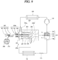
- FIG. 1 is a schematic diagram of a refrigeration cycle apparatus having an ejector according to an embodiment.
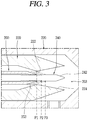
- FIG. 2 is an enlarged view of the ejector of FIG. 1 .
- a refrigeration cycle apparatus having an ejector may include a compressor 110 configured to compress a refrigerant; a high pressure side heat exchanger 130 connected to the compressor 110, and configured to cool the compressed refrigerant; a gas-liquid separator 150 connected to the compressor 110, and configured to separate the refrigerant therein into a gas phase and a liquid phase; an evaporator 170 connected to the gas-liquid separator 150, and configured to evaporate the refrigerant; and an ejector 190 having one or a first side connected to the high pressure side heat exchanger 130 and having another or a second side connected to the evaporator 170.
- the compressor 110 may suction in and compress a low temperature-low pressure gas refrigerant, and may discharge a high temperature-high pressure refrigerant.
- the gas-liquid separator 150 may be connected to a suction side of the compressor 110.
- the gas-liquid separator 150 may include a hermetic container 151, an inlet 152 formed at one side of the hermetic container 151, and a first outlet 154 and a second outlet 156 formed at another side of the hermetic container 151.
- a refrigerant may be divided into a gas refrigerant G and a liquid refrigerant L according to a specific gravity.
- the first outlet 154 may be formed such that the gas refrigerant G inside of the hermetic container 151 may be discharged therethrough.
- the second outlet 156 may be formed such that the liquid refrigerant L inside of the hermetic container 151 may be discharged therethrough.
- the inlet 152 may be connected to the ejector 190.
- the refrigerant of two phases in which gas and liquid are mixed with each other, discharged ejector 190, may be introduced into the hermetic container 151.
- the first outlet 154 may be connected to the compressor 110.
- the gas refrigerant separated inside of the hermetic container 151 may be suctioned into the compressor 110.
- the second outlet 156 may be connected to the evaporator 170.
- a throttle valve 175 may be provided at a suction side of the evaporator 170.
- the liquid refrigerant from the hermetic container 151 of the gas-liquid separator 150 may be depressurized and expanded after passing through the throttle valve 175.
- the refrigerant depressurized and expanded after passing through the throttle valve 175 may be evaporated at the evaporator 170 by absorbing latent heat.
- the high pressure side heat exchanger 130 may be connected to a discharge side of the compressor 110.
- the ejector 190 may include an ejector body 200 having an accommodation space therein, a suction part or portion 201, through which a high pressure refrigerant and a low pressure refrigerant may be suctioned into the accommodation space, and a mixing part or portion 203 configured to mix the high pressure refrigerant with the low pressure refrigerant; a nozzle 220 provided in the ejector body 200, having a nozzle neck 222 and an expansion portion 224, and configured to inject the high pressure refrigerant; a first needle 240 moveably provided at the expansion portion 224, and configured to control a flow sectional area of the expansion portion 224; a second needle 250 moveably provided at the nozzle neck 222, and configured to control a flow sectional area of the nozzle neck 222; a first needle driving unit or drive 270 configured to drive the first needle 240; and a second needle driving unit or drive 290 configured to drive the second needle 250.
- the ejector body 200 may be formed as a hollow body having therein the accommodation space.
- a high pressure refrigerant suction region 202a, into which a high pressure refrigerant having passed through the high pressure side heat exchanger 130 (hereinafter, referred to as 'high pressure refrigerant') may be suctioned, may be formed at one side of the ejector body 200.
- One or a first side of the ejector body 200 may be shielded from the outside.
- a shielding member 205 configured to shield the ejector body 200 from the outside may be provided at one side of the ejector body 200.
- Another or a second side of the ejector body 200 may be connected to the gas-liquid separator 150.
- a low pressure refrigerant suction region 202b, into which a low pressure refrigerant having passed through the evaporator 170 (hereinafter, referred to as 'low pressure refrigerant') may be suctioned, may be formed at another side of the ejector body 200.
- the nozzle 220 may be provided in the ejector body 200.
- the nozzle 220 may be provided with the nozzle neck 222 configured to inject the high pressure refrigerant at a high speed.
- the nozzle 220 may be provided with the expansion portion 224 configured to expand the refrigerant having passed through the nozzle neck 222.
- the first needle 240 may be provided in the expansion portion 224.
- the first needle 240 may be formed as a rod having a length greater than a diameter thereof.
- the first needle 240 may include a tapered portion 242 at one end thereof, an outer diameter of which decreases gradually.
- the first needle 240 may control a flow sectional area of the expansion portion 224 of the nozzle 220 to be increased or decreased, as the tapered portion 242 disposed in the expansion portion 224 is relatively moved with respect to the expansion portion 224 in an axial direction.
- the second needle 250 may be provided in the nozzle 220.
- the second needle 250 may be provided with a tapered portion 252 at one end thereof, an outer diameter of which decreases gradually.
- the tapered portion 252 of the second needle 250 may be disposed close to the nozzle neck 222 of the nozzle 220.
- the second needle 250 may control a flow sectional area of the nozzle neck 222 to be increased or decreased, as the tapered portion 252 disposed in the nozzle neck 222 is relatively moved with respect to the nozzle neck 222.
- the first needle 240 is penetratingly-coupled to an inside of the second needle 250.
- the first and second needles 240, 250 may be coupled to each other in a concentric (coaxial) manner.
- the first and second needles 240, 250 may be disposed at different positions according to a drive condition of a refrigeration cycle, for example, a refrigeration load amount.
- the drive condition may be classified into a first drive mode ('strong') where a refrigeration load amount is relatively large, a third drive mode ('weak') where a refrigeration load amount is relatively small, and a second drive mode ('middle') where a refrigeration load amount is smaller than that of the first drive mode, but is larger than that of the third drive mode.
- a first drive mode ('strong') where a refrigeration load amount is relatively large
- a third drive mode 'weak'
- 'middle' where a refrigeration load amount is smaller than that of the first drive mode, but is larger than that of the third drive mode.
- the second needle 250 may be moveable to one of a first position P1 corresponding to the first drive mode, a second position P2 corresponding to the second drive mode, and a third position P3 corresponding to the third drive mode.
- the first position P1 of the second needle 250 refers to a position where the end portion of the second needle 250 corresponds to the nozzle neck 222
- the second position P2 and the third position P3 may refer to positions where the end portion of the second needle 250 is moved close to the end portion of the first needle 240 by preset intervals, respectively.
- Efficiency of the ejector 190 may be increased when a flow sectional area (diameter) of the nozzle neck 222 of the nozzle 220 is relatively large in the first drive mode (the first position).
- a position of the first needle 240 may be controlled for enhanced efficiency of the cycle, such that a flow sectional area of the expansion portion 224 may be controlled. That is, for example, when the second needle 250 is disposed at one of the first to third positions, the first needle 240 may be moved in the axial direction for enhanced efficiency of the cycle, such that a flow sectional area of the expansion portion 224 may be properly increased or decreased.
- the position of the first needle 240 includes the first to third positions p1, p2 and p3.
- an increase of a flow sectional area of the expansion portion 224 does not always mean an increase in efficiency of the cycle.
- the first to third positions p1, p2 and p3 may be classified in to the first position p1 where the end portion of the first needle 240 is disposed inside the nozzle 220, the second position p2 where the end portion of the first needle 240 corresponds to the end portion of the nozzle 220 and the third position p3 where the end portion of the first needle 240 is disposed outside the nozzle 220.
- the first needle drive 270 configured to drive the first needle 240 in the axial direction may be provided at one side of the first needle 240.
- the first needle drive 270 may be a linear actuator having a piezoelectric device (piezo element) 272.
- the piezoelectric device 272 may be formed such that a displacement may be generated in the axial direction, in proportion to a voltage applied thereto.
- the piezoelectric device 272 may be configured to generate a displacement by being expanded or contracted in a thickness direction when a voltage is applied thereto.
- the first needle drive 270 may include a plurality of piezoelectric devices 272 laminated to each other in a thickness direction.
- the first needle drive 270 may include a fixing unit or device 274 provided at one side of the piezoelectric devices 272 and configured to fix the plurality of piezoelectric devices 272.
- the plurality of piezoelectric devices 272 may be fixed and supported by the fixing unit 274. Accordingly, as the first needle 240 connected to the plurality of piezoelectric devices 272 is relatively moved with respect to the nozzle 220, a flow sectional area (diameter) of the expansion portion 224 may be controlled.
- the second needle drive 290 configured to drive the second needle 250 may be provided at one side of the second needle 250.
- the second needle drive 290 may be an electric motor having a rotor 291 provided at the second needle 250, and having a stator 301 disposed around the rotor 291.
- the rotor 291 may include a permanent magnet 294 provided around the second needle 250.
- a permanent magnet coupling portion 260 concaved from an external surface of the second needle 250 so as to couple the permanent magnet 294 thereto, may be provided near the second needle 250.
- the permanent magnet 294 may have a cylindrical shape.
- the permanent magnet 294 may be provided at an outer surface of the second needle 250 for coupling.
- the permanent magnet 294 is formed to have a cylindrical shape.
- the stator 301 may be provided around the rotor 291.
- the stator 301 may include a stator core 303, and a stator coil 305 wound on the stator core 303.
- the permanent magnet 294 may have a length greater than a length in the axial direction of the stator 301. With such a configuration, even when the second needle 250 is relatively moved with respect to the first needle 240 in the axial direction when the permanent magnet 294 is rotated, a magnetic force may be smoothly generated between the permanent magnet 294 and the stator 301.
- the length in the axial direction of the permanent magnet 294 may be determined as a length long enough to generate a magnetic force to interact with the stator 301, considering a relatively moveable distance of the second needle 250 with respect to the nozzle neck 222.
- a stator supporting portion 307 configured to support the stator 301 may be provided at one side of the stator 301.
- one or a first side of the stator supporting portion 307 may be coupled to the stator core 303, and another or a second side thereof may be coupled to the first needle 240.
- stator supporting portion 307 is integrally fixed to an outer surface of the first needle 240.
- the refrigeration cycle apparatus having the ejector may be provided with a controller 320 configured to control a position of each of the first and second needles 240, 250 according to a drive condition.
- a drive mode selection unit or selector 325 configured to select a drive mode may be connected to the controller 320 in a communicable manner.
- the drive mode may be categorized into a plurality of drive modes according to a compression ratio or a refrigeration load amount.
- the plurality of drive modes may include a first mode where a compression ratio or a refrigeration load amount is relatively large, a third mode where a compression ratio or a refrigeration load amount is smaller than that of the first mode, and a second mode where a compression ratio or a refrigeration load amount is intermediate between that of the first mode and that of the third mode.
- the controller 320 may control the second needle drive 290 such that the second needle 250 may be moveable to one of the first to third positions, based on a drive mode selected by the drive mode selector 325.
- the controller 320 may control the first needle drive 270 such that the first needle 240 may be moveable in a direction to enhance a drive efficiency of the cycle.
- the controller 320 may control the first needle drive 270 such that a refrigerant pressure may be sensed and the sensed refrigerant pressure may reach a preset or predetermined pressure.
- the preset or predetermined pressure may be preset for maximization efficiency of the system, for example.
- the refrigerant pressure may be a condensation pressure and/or an evaporation pressure.
- a pressure sensor 330 configured to sense the refrigerant pressure may be connected to and communicated with the controller 320.
- the controller 320 may control the second needle drive 290 such that the second needle 250 may be disposed at a corresponding position according to the selected drive mode.
- the controller 320 may control the first needle drive 270 such that a refrigerant pressure at a preset or predetermined position may be sensed by the pressure sensor 330 and the sensed refrigerant pressure may reach a preset or predetermined pressure.
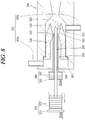
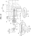
- FIGS. 6 to 8 Another embodiment will be explained with reference to FIGS. 6 to 8 .
- a refrigeration cycle apparatus having an ejector may include compressor 110 configured to compress a refrigerant; high pressure side heat exchanger 130 connected to the compressor 110, and configured to cool the compressed refrigerant; gas-liquid separator 150 connected to the compressor 110, and configured to separate the refrigerant therein into a gas phase G and a liquid phase L; evaporator 170 connected to the gas-liquid separator 150, and configured to evaporate the refrigerant; and an ejector 190a having one or a first side connected to the high pressure side heat exchanger 130 and having another or a second side connected to the evaporator 170.
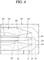
- the ejector 190a may include ejector body 200 having an accommodation space therein, suction portion 201 through which a high pressure refrigerant and a low pressure refrigerant may be suctioned into the accommodation space, and mixing portion 203 configured to mix the high pressure refrigerant with the low pressure refrigerant; nozzle 220 provided in the ejector body 200, nozzle neck 222 and expansion portion 224, and configured to inject the high pressure refrigerant; first needle 240 moveably provided at the expansion portion 224, and configured to control the flow sectional area of the expansion portion 224; second needle 250 moveably provided at the nozzle neck 222, and configured to control the flow sectional area of the nozzle neck 222; first needle drive 270 configured to drive the first needle 240; and a second needle driving unit or drive 340 configured to drive the second needle 250.
- the first needle 240 may be provided with tapered portion 242 at one end thereof, the outer width of which decreases gradually.
- the tapered portion 242 of the first needle 240 may be disposed in the expansion portion 224 of the nozzle 220.
- the second needle 250 may be provided with tapered portion 252 at one end thereof, the outer width of which decreases gradually.
- the tapered portion 252 of the second needle 250 may be disposed close to the nozzle neck 222.
- the first needle 240 is penetratingly-coupled to the inside of the second needle 250, so as to be relatively moveable with respect to the second needle 250 in the axial direction.
- a first needle accommodation opening 243 configured to accommodate the first needle 240 therein in a relatively-moveable manner may be provided in a middle of the second needle 250.
- the first needle accommodation opening 243 may be configured to support the first needle 240 so as to be relatively moveable in a concentric manner within the second needle 250.
- the first needle drive 270 configured to drive the first needle 240 may be provided outside of the ejector body 200.
- the first needle drive 270 may be formed as a linear actuator having a plurality of piezoelectric devices 272.
- the first needle drive 270 may include fixing unit 274 configured to fix the plurality of piezoelectric devices 272.
- the plurality of piezoelectric devices 272 When a voltage is applied to the plurality of piezoelectric devices 272 of the first needle drive 270, the plurality of piezoelectric devices 272 may be fixed and supported by the fixing unit 274. Accordingly, as the first needle 240 connected to the plurality of piezoelectric devices 272 is relatively moved with respect to the nozzle 220, the flow sectional area (diameter) of the expansion portion 224 may be controlled.
- the second needle drive 340 configured to drive the second needle 250 may be provided outside of the ejector body 200.
- the second needle drive 340 may be provided with a piezoelectric device 342, for example.
- the second needle drive 340 may be a linear actuator provided with a plurality of piezoelectric devices 342 laminated with each other in a thickness direction.
- the second needle drive 340 may be provided with a fixing unit or device 344 configured to support the plurality of piezoelectric devices 342.
- one or a first side of the plurality of piezoelectric devices 342 may be fixed and supported by the fixing unit 344. Accordingly, as the second needle 250 connected to another or a second side of the plurality of piezoelectric devices 342 is relatively moved with respect to the nozzle neck 222 of the nozzle 220, a flow sectional area (diameter) of the nozzle neck 222 may be controlled.
- the controller 320 may control a proper voltage to be applied to the plurality of piezoelectric devices 342 of the second needle drive 340. Accordingly, as the plurality of piezoelectric devices 342 of the second needle drive 340 are expanded or contracted, the tapered portion 252 of the second needle 250 may be relatively moved with respect to the nozzle neck 222. As a result, the flow sectional area of the nozzle neck 222 may be properly controlled.
- the controller 320 may control a proper voltage to be applied to the plurality of piezoelectric devices 272 of the first needle drive 270.
- the tapered portion 242 of the first needle 240 may be relatively moved with respect to the expansion portion 224 of the nozzle 220.
- the flow sectional area of the expansion portion 224 of the nozzle 220 may be properly controlled.
- a refrigeration cycle apparatus having an ejector may include compressor 110 configured to compress a refrigerant; high pressure side heat exchanger 130 connected to the compressor 110, and configured to cool the compressed refrigerant; gas-liquid separator 150 connected to the compressor 110, and configured to separate the refrigerant therein into a gas phase G and a liquid phase L; evaporator 170 connected to the gas-liquid separator 150, and configured to evaporate the refrigerant; and an ejector 190b having one or a first side connected to the high pressure side heat exchanger 130 and having another or a second side connected to the evaporator 170.
- the ejector 190b may include ejector body 200 having an accommodation space therein, suction portion 201 through which a high pressure refrigerant and a low pressure refrigerant may be suctioned into the accommodation space, and mixing portion 203 configured to mix the high pressure refrigerant with the low pressure refrigerant; nozzle 220 provided in the ejector body 200, having nozzle neck 222 and expansion portion 224, and configured to inject the high pressure refrigerant; first needle 240 moveably provided at the expansion portion 224, and configured to control a flow sectional area of the expansion portion 224; second needle 250 moveably provided at the nozzle neck 222, and configured to control the flow sectional area of the nozzle neck 222; a first needle driving unit or drive 360 configured to drive the first needle 240; and a second needle driving unit or drive 290a configured to drive the second needle 250.
- the first needle drive 360 configured to drive the first needle 240 may be provided outside of the ejector body 200.
- the first needle drive 360 may include a lead screw 362 disposed to be spaced from the first needle 240; a connection member 372 configured to connect the lead screw 362 and the first needle 240 with each other; and a lead screw drive portion or drive 382 configured to drive the lead screw 362.
- One or a first end of the connection member 372 may be connected to the first needle 240 so as to be relatively moveable, and a female screw portion 374 screw-coupled to the lead screw 362 may be provided at another or a second end of the connection member 372.
- the connection member 372 may be formed to have a 'U' shape.
- connection member 372 may include a first connection part or portion 373a connected to the first needle 240, a second connection part or portion 373b connected to the lead screw 362, and a third connection part or portion 373c configured to connect the first and second connection portions 373a, 373b with each other.
- the first connection portion 373a may be connected to the first needle 240 such that the first needle 240 may rotate in a relative manner.
- the second connection portion 373b may be connected to the lead screw 362 in a state in which the female screw portion 374 is interposed therebetween.
- the lead screw drive 382 may be an electric motor configured to generate a drive force when power is applied thereto.
- the lead screw drive (electric motor) 382 may be configured to perform a normal rotation and a counter rotation.
- a flow sectional area of the expansion portion 224 may be controlled.
- the first needle 240 may be penetratingly-coupled to the second needle 250.
- the second needle 250 may be coupled to an external surface of the first needle 240 in a relatively-moveable manner and in a slidable manner.
- Supporting units or supports 256 which may plane-contact an outer surface of the first needle 240, may be provided on an inner surface of the second needle 250.
- the supports 256 may be spaced from each other in the axial direction.
- a cut-out portion or cut-out 258, cut-out in a radial direction so as to be spaced from an outer surface of the first needle 240, may be formed between a female screw portion 228 and the support 256.
- the second needle 250 may be supported so as to be relatively rotatable with respect to the nozzle 220.
- a second needle supporting unit or support 225 configured to support the second needle 250 so as to be relatively-rotatable may be provided on an inner surface of the nozzle 220.
- the second needle support 225 may include a plurality of rods 226 spaced from each other in a circumferential direction of the nozzle 220, and a cylindrical part or portion 227 provided at a central region of the rods 226.
- the second needle 250 may be screw-coupled to the second needle support 225.
- a male screw portion 259 may be provided on an outer surface of the second needle 250.
- the female screw portion 228 screw-coupled to the male screw portion 259 may be provided at the second needle support 225.
- the female screw portion 228 may be provided at the cylindrical portion 227 of the second needle support 225.
- the second needle drive 290a configured to drive the second needle 250 may be provided outside of the ejector body 200.
- the second needle drive 290a may include a rotor 291 provided at the second needle 250, and a stator 301 provided around the rotor 291.
- the second needle drive 290a may be provided with a stator supporting portion or support 308 configured to support the stator 301.
- One or a first side of the stator support 308 may be coupled to an outer surface of the stator core 303.
- the stator support 308 may be forcibly-coupled to the stator core 303, for example.
- Another or a second side of the stator support 308 may be coupled to the ejector body 200.
- the stator support 308 may be coupled to shielding member 205 of the ejector body 200.
- Permanent magnet 294 may have a length greater than a length of the stator 301 in the axial direction.
- the controller 320 may control the second needle drive 290a such that the second needle 250 may perform a normal rotation or a counter rotation with respect to the nozzle 220.
- the male screw portion 259 of the second needle 250 may be relatively moved with respect to the female screw portion 228 of the second needle support 225, thereby moving in the axial direction.
- the tapered portion 252 of the second nozzle 250 may approach or move away from the nozzle neck 222, and the flow sectional area (diameter) of the nozzle neck 222 may be controlled.
- the controller 320 may control the lead screw drive 382 of the first needle drive 360 to perform a normal rotation or a counter rotation.
- the female screw portion 374 screw-coupled to the lead screw 362 may be relatively moved in the axial direction. Accordingly, as the first needle 240 connected to the expansion portion 224 of the nozzle 220 by the connection member 372 is relatively moved with respect to the expansion portion 224 of the nozzle 220, the flow sectional area of the expansion portion 224 may be controlled.
- a flow amount may be micro-controlled in correspondence to various drive conditions of the cycle, through various combinations of a diameter of the nozzle neck and a diameter of the expansion portion. This may enhance a drive efficiency of the cycle.
- first needle drive or the second needle drive is provided with piezoelectric devices, responsiveness may be enhanced. Furthermore, as the first needle drive or the second needle drive is provided with an electric motor, fabrication costs may be reduced.
- embodiments disclosed herein provide an ejector capable of independently controlling a flow sectional area of a nozzle neck and a flow sectional area of an expansion portion, and a refrigeration cycle apparatus having an ejector.
- Embodiments disclosed herein further provide an ejector capable of micro-controlling a flow amount through various combinations of a flow sectional area of a nozzle neck and a flow sectional area of an expansion portion of a nozzle, and a refrigeration cycle apparatus having an ejector.
- Embodiments disclosed herein provide an ejector that may include an ejector body having an accommodation space therein, having a suction part or portion through which a high pressure refrigerant and a low pressure refrigerant may be suctioned into the accommodation space, and having a mixing part or portion configured to mix the high pressure refrigerant with the low pressure refrigerant; a nozzle provided in the ejector body, having a nozzle neck and an expansion portion, and configured to inject the high pressure refrigerant; a first needle moveably provided at the expansion portion, and configured to control a flow sectional area of the expansion portion; a second needle moveably provided at the nozzle neck, and configured to control a flow sectional area of the nozzle neck; a first needle driving unit or drive configured to drive the first needle; and a second needle driving unit or drive configured to drive the second needle.
- the first needle may be provided with a tapered portion having its outer width decreased gradually. The tapered portion of the first needle may be disposed in the expansion portion
- the second needle may be provided with a tapered portion having its outer width decreased gradually.
- the tapered portion of the second needle may be disposed close to the nozzle neck of the nozzle.
- the first needle is penetratingly-coupled to the second needle so as to be relatively moveable.
- the first needle may be penetratingly-coupled to the second needle by screws.
- the first needle driving unit may be provided with piezoelectric devices.
- the piezoelectric devices may move the first needle in a shaft or axial direction, by being expanded and contracted when a voltage is applied thereto.
- a fixing unit configured to fix and support the piezoelectric devices may be formed at one side of the piezoelectric devices.
- the second needle driving unit may be formed as an electric motor having a rotor provided at the second needle and having a stator provided around the rotor.
- the rotor may be provided with a permanent magnet inserted into a surface of the second needle.
- the permanent magnet may have a cylindrical shape, or may be provided with a plurality of arc-shaped segment magnets.
- a male screw portion may be formed on an outer surface of the first needle, and a female screw portion may be formed on an inner surface of the second needle.
- a supporting unit or support, rotatable and slidable on an outer surface of the first needle, may be formed at one side of the female screw portion.
- the female screw portion and the supporting unit may be spaced from each other.
- a cut-out portion or cut-out, cut-out so as to be spaced from a surface of the first needle, may be formed between the female screw portion and the supporting unit.
- the second needle driving unit may be provided with piezoelectric devices.
- the piezoelectric devices may move the second needle in a shaft or axial direction, by being expanded and contracted when a voltage is applied thereto.
- a fixing unit configured to fix and support the piezoelectric devices may be formed at one side of the piezoelectric devices.
- the first needle driving unit may include a lead screw disposed to be spaced from the first needle; a connection member configured to connect the lead screw and the first needle with each other; and a lead screw driving portion configured to drive the lead screw.
- One or a first end of the connection member may be connected to the first needle so as to be relatively moveable, and a female screw portion screw-coupled to the lead screw may be provided at another or a second end of the connection member.
- the lead screw driving portion may be provided with an electric motor.
- Embodiments disclosed herein further provide a refrigeration cycle apparatus having an ejector that may include a compressor configured to compress a refrigerant; a high pressure side heat exchanger connected to the compressor, and configured to cool a high pressure refrigerant; a gas-liquid separator connected to the compressor, and configured to separate a refrigerant which exists therein into a gas phase and a liquid phase; an evaporator connected to the gas-liquid separator, and configured to evaporate a refrigerant; and the ejector having one or a first side connected to the high pressure side heat exchanger, and having another or a second side connected to the evaporator.
- the refrigeration cycle apparatus having an ejector may further include a throttle valve provided between the evaporator and the gas-liquid separator, and configured to control a flow sectional area of a flow path which connects the evaporator with the gas-liquid separator.
- the refrigeration cycle apparatus having an ejector may further include a drive mode selection unit or selector configured to select one of a plurality of drive modes, and a controller configured to control first and second needle drive units or drives, based on a drive mode selected by the driving mode selection unit.
- any reference in this specification to "one embodiment,” “an embodiment,” “example embodiment,” etc. means that a particular feature, structure, or characteristic described in connection with the embodiment is included in at least one embodiment.
- the appearances of such phrases in various places in the specification are not necessarily all referring to the same embodiment.
Landscapes
- Engineering & Computer Science (AREA)
- Physics & Mathematics (AREA)
- Mechanical Engineering (AREA)
- Thermal Sciences (AREA)
- General Engineering & Computer Science (AREA)
- Jet Pumps And Other Pumps (AREA)
- Nozzles (AREA)
Claims (14)
- Ausstoßeinrichtung, die Folgendes umfasst:einen Ausstoßkörper (200), der einen Aufnahmeraum, einen Saugabschnitt (201), durch den ein Kühlmittel mit hohem Druck und ein Kühlmittel mit niedrigem Druck in den Aufnahmeraum gesaugt werden, und einen Mischabschnitt (203), der konfiguriert ist, das Kühlmittel mit hohem Druck mit dem Kühlmittel mit niedrigem Druck zu mischen, aufweist;eine Düse (220), die in dem Ausstoßkörper (200) vorgesehen ist, die einen Düsenhals (222) und einen Expansionsabschnitt (224) aufweist und konfiguriert ist, das Kühlmittel mit hohem Druck in den Mischabschnitt (203) einzuspritzen;eine erste Nadel (240), die bei dem Expansionsabschnitt (224) beweglich vorgesehen ist und konfiguriert ist, eine Strömungsquerschnittsfläche des Expansionsabschnitts (224) zu steuern;eine zweite Nadel (250), die bei dem Düsenhals (222) beweglich vorgesehen ist und konfiguriert ist, eine Strömungsquerschnittsfläche des Düsenhalses (222) zu steuern;einen ersten Nadelantrieb (270), der konfiguriert ist, die erste Nadel (240) anzutreiben; undeinen zweiten Nadelantrieb (290), der konfiguriert ist, die zweite Nadel (250) anzutreiben,dadurch gekennzeichnet, dass
die erste Nadel (240) mit der zweiten Nadel (250) mittels Durchdringung so gekoppelt ist, dass sie relativ zur zweiten Nadel (250) bewegt werden kann. - Ausstoßeinrichtung nach Anspruch 1, wobei die erste und/oder die zweite Nadel (240, 250) mit einem konisch zulaufenden Abschnitt (242, 252) versehen ist, wovon eine äußere Breite schrittweise abnimmt.
- Ausstoßeinrichtung nach Anspruch 1 oder 2, wobei die erste Nadel (240) mit der zweiten Nadel (250) mittels Durchdringung über ein Gewinde gekoppelt ist.
- Ausstoßeinrichtung nach einem der vorhergehenden Ansprüche, wobei der Antrieb (270) der ersten Nadel piezoelektrische Vorrichtungen (272) umfasst.
- Ausstoßeinrichtung nach einem der vorhergehenden Ansprüche, wobei der Antrieb (290) der zweiten Nadel Folgendes umfasst:einen Rotor (291), der an der zweiten Nadel (250) vorgesehen ist; undeinen Stator (301), der um den Rotor (291) vorgesehen ist.
- Ausstoßeinrichtung nach Anspruch 5, wobei der Rotor (291) mit einem Permanentmagneten (294) versehen ist, der an einer Oberfläche der zweiten Nadel (250) vorgesehen ist.
- Ausstoßeinrichtung nach einem der vorhergehenden Ansprüche, wobei ein Außengewindeabschnitt (259) an einer äußeren Oberfläche der ersten Nadel (240) ausgebildet ist, wobei ein Innengewindeabschnitt (228) an einer inneren Oberfläche der zweiten Nadel (250) ausgebildet ist und wobei eine Halterung (256), die drehbar ist und auf einer äußeren Oberfläche der ersten Nadel (240) gleiten kann, an einer Seite des Innengewindeabschnitts (254) ausgebildet ist.
- Ausstoßeinrichtung nach Anspruch 7, wobei der Innengewindeabschnitt (228) und die Halterung (256) voneinander beabstandet sind und wobei eine Aussparung (258), die von einer Oberfläche der ersten Nadel (240) beabstandet ist, zwischen dem Innengewindeabschnitt (228) und der Halterung (256) ausgebildet ist.
- Ausstoßeinrichtung nach einem der Ansprüche 1 bis 8, wobei der Antrieb (340) der zweiten Nadel piezoelektrische Vorrichtungen (342) umfasst.
- Ausstoßeinrichtung nach einem der Ansprüche 1 bis 9, wobei der Antrieb (360) der ersten Nadel Folgendes umfasst:eine Leitspindel (362), die von der ersten Nadel (240) beabstandet ist;ein Verbindungselement (372), das konfiguriert ist, die Leitspindel (362) und die erste Nadel (240) miteinander zu verbinden; undeinen Antrieb (382) für die Leitspindel, der konfiguriert ist, die Leitspindel anzutreiben.
- Ausstoßeinrichtung nach Anspruch 10, wobei ein erstes Ende des Verbindungselements (372) mit der ersten Nadel (240) so verbunden ist, dass es relativ zur ersten Nadel (240) bewegt werden kann, und wobei ein Innengewindeabschnitt (374), der mit der Führungsschraube (362) über eine Schraubverbindung gekoppelt ist, an einem zweiten Ende des Verbindungselements (372) vorgesehen ist.
- Ausstoßeinrichtung nach Anspruch 10 oder 11, wobei der Antrieb der Führungsschraube einen Elektromotor (382) umfasst.
- Kühlkreislaufvorrichtung, die eine Ausstoßeinrichtung aufweist, wobei die Kühlkreislaufvorrichtung Folgendes umfasst:einen Kompressor (110), der konfiguriert ist, ein Kühlmittel zu komprimieren;einen Wärmetauscher (130) auf der Hochdruckseite, der mit dem Kompressor (110) verbunden ist und konfiguriert ist, das komprimierte Kühlmittel zu kühlen;einen Gas/Flüssigkeit-Separator (150), der mit dem Kompressor (110) verbunden ist und konfiguriert ist, das Kühlmittel in eine Gasphase und eine flüssige Phase zu trennen;einen Verdampfer (170), der mit dem Gas/Flüssigkeit-Separator (150) verbunden ist und konfiguriert ist, das Kühlmittel zu verdampfen; unddie Ausstoßeinrichtung nach einem der Ansprüche 1 bis 12, wobei die Ausstoßeinrichtung (200) eine erste Seite aufweist, die mit dem Wärmetauscher (130) auf der Hochdruckseite verbunden ist, und eine zweite Seite aufweist, die mit dem Verdampfer (170) verbunden ist.
- Kühlkreislaufvorrichtung nach Anspruch 13, die ferner Folgendes umfasst:eine Antriebbetriebsart-Auswahlvorrichtung (325), die konfiguriert ist, eine von mehreren Antriebsbetriebsarten auszuwählen; undeine Steuerung (320), die konfiguriert ist, auf der Basis einer Antriebsbetriebsart, die durch die Antriebsbetriebsart-Auswahlvorrichtung (325) ausgewählt wurde, die Antriebe (270, 290) der ersten und der zweiten Nadel zu steuern.
Applications Claiming Priority (1)
| Application Number | Priority Date | Filing Date | Title |
|---|---|---|---|
| KR1020160141233A KR101838636B1 (ko) | 2016-10-27 | 2016-10-27 | 이젝터 및 이를 구비한 냉동사이클 장치 |
Publications (2)
| Publication Number | Publication Date |
|---|---|
| EP3315879A1 EP3315879A1 (de) | 2018-05-02 |
| EP3315879B1 true EP3315879B1 (de) | 2019-02-13 |
Family
ID=59523005
Family Applications (1)
| Application Number | Title | Priority Date | Filing Date |
|---|---|---|---|
| EP17184724.7A Not-in-force EP3315879B1 (de) | 2016-10-27 | 2017-08-03 | Auswerfer und kältekreislaufvorrichtung mit einem auswerfer |
Country Status (4)
| Country | Link |
|---|---|
| US (1) | US10345018B2 (de) |
| EP (1) | EP3315879B1 (de) |
| KR (1) | KR101838636B1 (de) |
| CN (1) | CN108007008B (de) |
Families Citing this family (5)
| Publication number | Priority date | Publication date | Assignee | Title |
|---|---|---|---|---|
| CN110398131B (zh) | 2019-07-24 | 2020-06-02 | 西安交通大学 | 一种引射式冷能回收低温冷却装置 |
| KR102267893B1 (ko) | 2019-12-24 | 2021-06-23 | 한국에너지기술연구원 | 멤브레인을 이용한 냉각 장치 및 이를 이용한 냉각 방법 |
| KR102295566B1 (ko) | 2020-10-26 | 2021-08-31 | 한국에너지기술연구원 | 이젝터와 멤브레인을 이용한 냉방 시스템 |
| CN118988587A (zh) * | 2023-05-22 | 2024-11-22 | 开利公司 | 喷射器以及具有其的制冷系统 |
| CN120175691A (zh) * | 2023-12-18 | 2025-06-20 | 开利公司 | 喷射器及制冷系统 |
Family Cites Families (24)
| Publication number | Priority date | Publication date | Assignee | Title |
|---|---|---|---|---|
| JP3327934B2 (ja) | 1991-09-06 | 2002-09-24 | 株式会社東芝 | 蒸気インジェクタ |
| JPH05312421A (ja) * | 1992-05-14 | 1993-11-22 | Nippondenso Co Ltd | 冷凍装置 |
| JP3310042B2 (ja) | 1993-02-16 | 2002-07-29 | 株式会社不二工機 | 電動弁用のロータ中心体とロータ送りねじ及びロータの製造方法 |
| JP4599782B2 (ja) | 2001-09-19 | 2010-12-15 | 株式会社デンソー | エジェクタを用いた冷凍サイクル |
| JP3941602B2 (ja) | 2002-02-07 | 2007-07-04 | 株式会社デンソー | エジェクタ方式の減圧装置 |
| JP4120296B2 (ja) | 2002-07-09 | 2008-07-16 | 株式会社デンソー | エジェクタおよびエジェクタサイクル |
| JP3966157B2 (ja) | 2002-10-25 | 2007-08-29 | 株式会社デンソー | エジェクタ |
| JP4232484B2 (ja) * | 2003-03-05 | 2009-03-04 | 株式会社日本自動車部品総合研究所 | エジェクタおよび蒸気圧縮式冷凍機 |
| JP4273977B2 (ja) | 2004-01-21 | 2009-06-03 | 株式会社デンソー | エジェクタサイクル |
| JP4069880B2 (ja) * | 2004-02-18 | 2008-04-02 | 株式会社デンソー | エジェクタ |
| JP4367168B2 (ja) * | 2004-02-20 | 2009-11-18 | 株式会社日本自動車部品総合研究所 | 流量可変ノズル |
| JP4134931B2 (ja) * | 2004-03-30 | 2008-08-20 | 株式会社デンソー | エジェクタ |
| JP4572910B2 (ja) * | 2007-06-11 | 2010-11-04 | 株式会社デンソー | 二段減圧式エジェクタおよびエジェクタ式冷凍サイクル |
| JP5269407B2 (ja) * | 2007-12-14 | 2013-08-21 | 株式会社テイエルブイ | 蒸気エゼクタ |
| JP4814963B2 (ja) * | 2009-02-13 | 2011-11-16 | 本田技研工業株式会社 | エゼクタおよびこのエゼクタを用いた燃料電池システム |
| WO2012074650A1 (en) * | 2010-11-30 | 2012-06-07 | Carrier Corporation | Ejector |
| US9285146B2 (en) * | 2011-01-04 | 2016-03-15 | Carrier Corporation | Ejector |
| ITMI20112261A1 (it) * | 2011-12-14 | 2013-06-15 | Eni Spa | Eiettore multifase ad assetto variabile per recupero di produzione a testa pozzo |
| CN104718419A (zh) * | 2012-10-10 | 2015-06-17 | 松下知识产权经营株式会社 | 热交换装置以及热泵装置 |
| JP2016044964A (ja) * | 2014-08-21 | 2016-04-04 | パナソニックIpマネジメント株式会社 | 冷凍サイクル装置 |
| JP6792293B2 (ja) * | 2015-04-15 | 2020-11-25 | ユニバーシティー オブ デラウェア | 可変流量燃料排出のための装置、システム及び方法 |
| CN106322807B (zh) * | 2015-07-03 | 2021-05-28 | 开利公司 | 喷射器热泵 |
| KR102380053B1 (ko) * | 2015-10-16 | 2022-03-29 | 삼성전자주식회사 | 공기조화장치, 이에 사용되는 이젝터, 및 공기조화장치의 제어방법 |
| KR101794757B1 (ko) * | 2016-06-13 | 2017-12-01 | 엘지전자 주식회사 | 이젝터 및 이를 구비한 냉동사이클 장치 |
-
2016
- 2016-10-27 KR KR1020160141233A patent/KR101838636B1/ko active Active
-
2017
- 2017-03-02 US US15/447,585 patent/US10345018B2/en active Active
- 2017-06-13 CN CN201710440935.5A patent/CN108007008B/zh not_active Expired - Fee Related
- 2017-08-03 EP EP17184724.7A patent/EP3315879B1/de not_active Not-in-force
Non-Patent Citations (1)
| Title |
|---|
| None * |
Also Published As
| Publication number | Publication date |
|---|---|
| EP3315879A1 (de) | 2018-05-02 |
| CN108007008B (zh) | 2020-06-09 |
| US10345018B2 (en) | 2019-07-09 |
| CN108007008A (zh) | 2018-05-08 |
| KR101838636B1 (ko) | 2018-03-14 |
| US20180120004A1 (en) | 2018-05-03 |
Similar Documents
| Publication | Publication Date | Title |
|---|---|---|
| EP3315879B1 (de) | Auswerfer und kältekreislaufvorrichtung mit einem auswerfer | |
| US9803770B2 (en) | Motor operated valve | |
| DK2646763T3 (en) | Ejector. | |
| CN105579788B (zh) | 喷射器式制冷循环 | |
| US6904769B2 (en) | Ejector-type depressurizer for vapor compression refrigeration system | |
| US10215196B2 (en) | Ejector using swirl flow | |
| US11959561B2 (en) | Electronic expansion valve and refrigeration system | |
| JP2012082896A (ja) | 電動弁 | |
| CN107490207B (zh) | 喷射器及具有该喷射器的制冷循环装置 | |
| CN105492778B (zh) | 喷射器 | |
| WO2014103276A1 (ja) | エジェクタ | |
| KR102796832B1 (ko) | 전자 팽창 밸브 및 상기 전자 팽창 밸브를 사용한 공조 시스템 | |
| CN110173586A (zh) | 电动阀以及冷冻循环系统 | |
| CN104428541A (zh) | 喷射器 | |
| US20040031286A1 (en) | Suction connection for dual centrifugal compressor refrigeration systems | |
| WO2014091701A1 (ja) | エジェクタ | |
| US20200068668A1 (en) | Magnetic induction style furnace or heat pump incorporating forced air or fluid blowers | |
| WO2014108974A1 (ja) | エジェクタ | |
| WO2015111113A1 (ja) | エジェクタ | |
| KR20200093327A (ko) | 전열관 및 칠러용 열교환기 | |
| JP2019045058A (ja) | 流量調節弁 | |
| CN108603519B (zh) | 喷射器 | |
| JP2017089963A (ja) | エジェクタ式冷凍サイクル | |
| WO2020096970A1 (en) | Magnetic induction style furnace or heat pump incorporating forced air or fluid blowers | |
| KR19990032266A (ko) | 유량제어용 밸브 |
Legal Events
| Date | Code | Title | Description |
|---|---|---|---|
| PUAI | Public reference made under article 153(3) epc to a published international application that has entered the european phase |
Free format text: ORIGINAL CODE: 0009012 |
|
| STAA | Information on the status of an ep patent application or granted ep patent |
Free format text: STATUS: THE APPLICATION HAS BEEN PUBLISHED |
|
| AK | Designated contracting states |
Kind code of ref document: A1 Designated state(s): AL AT BE BG CH CY CZ DE DK EE ES FI FR GB GR HR HU IE IS IT LI LT LU LV MC MK MT NL NO PL PT RO RS SE SI SK SM TR |
|
| AX | Request for extension of the european patent |
Extension state: BA ME |
|
| STAA | Information on the status of an ep patent application or granted ep patent |
Free format text: STATUS: REQUEST FOR EXAMINATION WAS MADE |
|
| 17P | Request for examination filed |
Effective date: 20180625 |
|
| RBV | Designated contracting states (corrected) |
Designated state(s): AL AT BE BG CH CY CZ DE DK EE ES FI FR GB GR HR HU IE IS IT LI LT LU LV MC MK MT NL NO PL PT RO RS SE SI SK SM TR |
|
| GRAP | Despatch of communication of intention to grant a patent |
Free format text: ORIGINAL CODE: EPIDOSNIGR1 |
|
| STAA | Information on the status of an ep patent application or granted ep patent |
Free format text: STATUS: GRANT OF PATENT IS INTENDED |
|
| INTG | Intention to grant announced |
Effective date: 20180821 |
|
| GRAS | Grant fee paid |
Free format text: ORIGINAL CODE: EPIDOSNIGR3 |
|
| GRAA | (expected) grant |
Free format text: ORIGINAL CODE: 0009210 |
|
| STAA | Information on the status of an ep patent application or granted ep patent |
Free format text: STATUS: THE PATENT HAS BEEN GRANTED |
|
| AK | Designated contracting states |
Kind code of ref document: B1 Designated state(s): AL AT BE BG CH CY CZ DE DK EE ES FI FR GB GR HR HU IE IS IT LI LT LU LV MC MK MT NL NO PL PT RO RS SE SI SK SM TR |
|
| REG | Reference to a national code |
Ref country code: GB Ref legal event code: FG4D |
|
| REG | Reference to a national code |
Ref country code: CH Ref legal event code: EP Ref country code: AT Ref legal event code: REF Ref document number: 1096448 Country of ref document: AT Kind code of ref document: T Effective date: 20190215 |
|
| REG | Reference to a national code |
Ref country code: IE Ref legal event code: FG4D |
|
| REG | Reference to a national code |
Ref country code: DE Ref legal event code: R096 Ref document number: 602017002133 Country of ref document: DE |
|
| REG | Reference to a national code |
Ref country code: LT Ref legal event code: MG4D |
|
| REG | Reference to a national code |
Ref country code: NL Ref legal event code: MP Effective date: 20190213 |
|
| PG25 | Lapsed in a contracting state [announced via postgrant information from national office to epo] |
Ref country code: SE Free format text: LAPSE BECAUSE OF FAILURE TO SUBMIT A TRANSLATION OF THE DESCRIPTION OR TO PAY THE FEE WITHIN THE PRESCRIBED TIME-LIMIT Effective date: 20190213 Ref country code: NL Free format text: LAPSE BECAUSE OF FAILURE TO SUBMIT A TRANSLATION OF THE DESCRIPTION OR TO PAY THE FEE WITHIN THE PRESCRIBED TIME-LIMIT Effective date: 20190213 Ref country code: LT Free format text: LAPSE BECAUSE OF FAILURE TO SUBMIT A TRANSLATION OF THE DESCRIPTION OR TO PAY THE FEE WITHIN THE PRESCRIBED TIME-LIMIT Effective date: 20190213 Ref country code: FI Free format text: LAPSE BECAUSE OF FAILURE TO SUBMIT A TRANSLATION OF THE DESCRIPTION OR TO PAY THE FEE WITHIN THE PRESCRIBED TIME-LIMIT Effective date: 20190213 Ref country code: PT Free format text: LAPSE BECAUSE OF FAILURE TO SUBMIT A TRANSLATION OF THE DESCRIPTION OR TO PAY THE FEE WITHIN THE PRESCRIBED TIME-LIMIT Effective date: 20190613 Ref country code: NO Free format text: LAPSE BECAUSE OF FAILURE TO SUBMIT A TRANSLATION OF THE DESCRIPTION OR TO PAY THE FEE WITHIN THE PRESCRIBED TIME-LIMIT Effective date: 20190513 |
|
| PG25 | Lapsed in a contracting state [announced via postgrant information from national office to epo] |
Ref country code: BG Free format text: LAPSE BECAUSE OF FAILURE TO SUBMIT A TRANSLATION OF THE DESCRIPTION OR TO PAY THE FEE WITHIN THE PRESCRIBED TIME-LIMIT Effective date: 20190513 Ref country code: RS Free format text: LAPSE BECAUSE OF FAILURE TO SUBMIT A TRANSLATION OF THE DESCRIPTION OR TO PAY THE FEE WITHIN THE PRESCRIBED TIME-LIMIT Effective date: 20190213 Ref country code: HR Free format text: LAPSE BECAUSE OF FAILURE TO SUBMIT A TRANSLATION OF THE DESCRIPTION OR TO PAY THE FEE WITHIN THE PRESCRIBED TIME-LIMIT Effective date: 20190213 Ref country code: IS Free format text: LAPSE BECAUSE OF FAILURE TO SUBMIT A TRANSLATION OF THE DESCRIPTION OR TO PAY THE FEE WITHIN THE PRESCRIBED TIME-LIMIT Effective date: 20190613 Ref country code: LV Free format text: LAPSE BECAUSE OF FAILURE TO SUBMIT A TRANSLATION OF THE DESCRIPTION OR TO PAY THE FEE WITHIN THE PRESCRIBED TIME-LIMIT Effective date: 20190213 |
|
| REG | Reference to a national code |
Ref country code: AT Ref legal event code: MK05 Ref document number: 1096448 Country of ref document: AT Kind code of ref document: T Effective date: 20190213 |
|
| PG25 | Lapsed in a contracting state [announced via postgrant information from national office to epo] |
Ref country code: CZ Free format text: LAPSE BECAUSE OF FAILURE TO SUBMIT A TRANSLATION OF THE DESCRIPTION OR TO PAY THE FEE WITHIN THE PRESCRIBED TIME-LIMIT Effective date: 20190213 Ref country code: AL Free format text: LAPSE BECAUSE OF FAILURE TO SUBMIT A TRANSLATION OF THE DESCRIPTION OR TO PAY THE FEE WITHIN THE PRESCRIBED TIME-LIMIT Effective date: 20190213 Ref country code: SK Free format text: LAPSE BECAUSE OF FAILURE TO SUBMIT A TRANSLATION OF THE DESCRIPTION OR TO PAY THE FEE WITHIN THE PRESCRIBED TIME-LIMIT Effective date: 20190213 Ref country code: IT Free format text: LAPSE BECAUSE OF FAILURE TO SUBMIT A TRANSLATION OF THE DESCRIPTION OR TO PAY THE FEE WITHIN THE PRESCRIBED TIME-LIMIT Effective date: 20190213 Ref country code: DK Free format text: LAPSE BECAUSE OF FAILURE TO SUBMIT A TRANSLATION OF THE DESCRIPTION OR TO PAY THE FEE WITHIN THE PRESCRIBED TIME-LIMIT Effective date: 20190213 Ref country code: EE Free format text: LAPSE BECAUSE OF FAILURE TO SUBMIT A TRANSLATION OF THE DESCRIPTION OR TO PAY THE FEE WITHIN THE PRESCRIBED TIME-LIMIT Effective date: 20190213 Ref country code: RO Free format text: LAPSE BECAUSE OF FAILURE TO SUBMIT A TRANSLATION OF THE DESCRIPTION OR TO PAY THE FEE WITHIN THE PRESCRIBED TIME-LIMIT Effective date: 20190213 Ref country code: ES Free format text: LAPSE BECAUSE OF FAILURE TO SUBMIT A TRANSLATION OF THE DESCRIPTION OR TO PAY THE FEE WITHIN THE PRESCRIBED TIME-LIMIT Effective date: 20190213 |
|
| REG | Reference to a national code |
Ref country code: DE Ref legal event code: R097 Ref document number: 602017002133 Country of ref document: DE |
|
| PG25 | Lapsed in a contracting state [announced via postgrant information from national office to epo] |
Ref country code: PL Free format text: LAPSE BECAUSE OF FAILURE TO SUBMIT A TRANSLATION OF THE DESCRIPTION OR TO PAY THE FEE WITHIN THE PRESCRIBED TIME-LIMIT Effective date: 20190213 Ref country code: SM Free format text: LAPSE BECAUSE OF FAILURE TO SUBMIT A TRANSLATION OF THE DESCRIPTION OR TO PAY THE FEE WITHIN THE PRESCRIBED TIME-LIMIT Effective date: 20190213 |
|
| PLBE | No opposition filed within time limit |
Free format text: ORIGINAL CODE: 0009261 |
|
| STAA | Information on the status of an ep patent application or granted ep patent |
Free format text: STATUS: NO OPPOSITION FILED WITHIN TIME LIMIT |
|
| PG25 | Lapsed in a contracting state [announced via postgrant information from national office to epo] |
Ref country code: AT Free format text: LAPSE BECAUSE OF FAILURE TO SUBMIT A TRANSLATION OF THE DESCRIPTION OR TO PAY THE FEE WITHIN THE PRESCRIBED TIME-LIMIT Effective date: 20190213 |
|
| 26N | No opposition filed |
Effective date: 20191114 |
|
| PG25 | Lapsed in a contracting state [announced via postgrant information from national office to epo] |
Ref country code: TR Free format text: LAPSE BECAUSE OF FAILURE TO SUBMIT A TRANSLATION OF THE DESCRIPTION OR TO PAY THE FEE WITHIN THE PRESCRIBED TIME-LIMIT Effective date: 20190213 |
|
| PG25 | Lapsed in a contracting state [announced via postgrant information from national office to epo] |
Ref country code: LU Free format text: LAPSE BECAUSE OF NON-PAYMENT OF DUE FEES Effective date: 20190803 Ref country code: MC Free format text: LAPSE BECAUSE OF FAILURE TO SUBMIT A TRANSLATION OF THE DESCRIPTION OR TO PAY THE FEE WITHIN THE PRESCRIBED TIME-LIMIT Effective date: 20190213 |
|
| REG | Reference to a national code |
Ref country code: BE Ref legal event code: MM Effective date: 20190831 |
|
| PG25 | Lapsed in a contracting state [announced via postgrant information from national office to epo] |
Ref country code: IE Free format text: LAPSE BECAUSE OF NON-PAYMENT OF DUE FEES Effective date: 20190803 Ref country code: FR Free format text: LAPSE BECAUSE OF NON-PAYMENT OF DUE FEES Effective date: 20190831 |
|
| PG25 | Lapsed in a contracting state [announced via postgrant information from national office to epo] |
Ref country code: BE Free format text: LAPSE BECAUSE OF NON-PAYMENT OF DUE FEES Effective date: 20190831 |
|
| REG | Reference to a national code |
Ref country code: CH Ref legal event code: PL |
|
| PG25 | Lapsed in a contracting state [announced via postgrant information from national office to epo] |
Ref country code: CH Free format text: LAPSE BECAUSE OF NON-PAYMENT OF DUE FEES Effective date: 20200831 Ref country code: LI Free format text: LAPSE BECAUSE OF NON-PAYMENT OF DUE FEES Effective date: 20200831 |
|
| PG25 | Lapsed in a contracting state [announced via postgrant information from national office to epo] |
Ref country code: CY Free format text: LAPSE BECAUSE OF FAILURE TO SUBMIT A TRANSLATION OF THE DESCRIPTION OR TO PAY THE FEE WITHIN THE PRESCRIBED TIME-LIMIT Effective date: 20190213 |
|
| PG25 | Lapsed in a contracting state [announced via postgrant information from national office to epo] |
Ref country code: GR Free format text: LAPSE BECAUSE OF FAILURE TO SUBMIT A TRANSLATION OF THE DESCRIPTION OR TO PAY THE FEE WITHIN THE PRESCRIBED TIME-LIMIT Effective date: 20190213 |
|
| PG25 | Lapsed in a contracting state [announced via postgrant information from national office to epo] |
Ref country code: MT Free format text: LAPSE BECAUSE OF FAILURE TO SUBMIT A TRANSLATION OF THE DESCRIPTION OR TO PAY THE FEE WITHIN THE PRESCRIBED TIME-LIMIT Effective date: 20190213 Ref country code: HU Free format text: LAPSE BECAUSE OF FAILURE TO SUBMIT A TRANSLATION OF THE DESCRIPTION OR TO PAY THE FEE WITHIN THE PRESCRIBED TIME-LIMIT; INVALID AB INITIO Effective date: 20170803 |
|
| PG25 | Lapsed in a contracting state [announced via postgrant information from national office to epo] |
Ref country code: SI Free format text: LAPSE BECAUSE OF FAILURE TO SUBMIT A TRANSLATION OF THE DESCRIPTION OR TO PAY THE FEE WITHIN THE PRESCRIBED TIME-LIMIT Effective date: 20190213 |
|
| GBPC | Gb: european patent ceased through non-payment of renewal fee |
Effective date: 20210803 |
|
| PG25 | Lapsed in a contracting state [announced via postgrant information from national office to epo] |
Ref country code: MK Free format text: LAPSE BECAUSE OF FAILURE TO SUBMIT A TRANSLATION OF THE DESCRIPTION OR TO PAY THE FEE WITHIN THE PRESCRIBED TIME-LIMIT Effective date: 20190213 |
|
| PG25 | Lapsed in a contracting state [announced via postgrant information from national office to epo] |
Ref country code: GB Free format text: LAPSE BECAUSE OF NON-PAYMENT OF DUE FEES Effective date: 20210803 |
|
| PGFP | Annual fee paid to national office [announced via postgrant information from national office to epo] |
Ref country code: DE Payment date: 20220615 Year of fee payment: 6 |
|
| REG | Reference to a national code |
Ref country code: DE Ref legal event code: R119 Ref document number: 602017002133 Country of ref document: DE |
|
| PG25 | Lapsed in a contracting state [announced via postgrant information from national office to epo] |
Ref country code: DE Free format text: LAPSE BECAUSE OF NON-PAYMENT OF DUE FEES Effective date: 20240301 |