EP3315362A1 - Duschvorrichtung und damit ausgestattetes nutzfahrzeug - Google Patents
Duschvorrichtung und damit ausgestattetes nutzfahrzeug Download PDFInfo
- Publication number
- EP3315362A1 EP3315362A1 EP17196879.5A EP17196879A EP3315362A1 EP 3315362 A1 EP3315362 A1 EP 3315362A1 EP 17196879 A EP17196879 A EP 17196879A EP 3315362 A1 EP3315362 A1 EP 3315362A1
- Authority
- EP
- European Patent Office
- Prior art keywords
- bellows
- cab
- driver
- trough
- lower opening
- Prior art date
- Legal status (The legal status is an assumption and is not a legal conclusion. Google has not performed a legal analysis and makes no representation as to the accuracy of the status listed.)
- Granted
Links
Images



Classifications
-
- B—PERFORMING OPERATIONS; TRANSPORTING
- B60—VEHICLES IN GENERAL
- B60R—VEHICLES, VEHICLE FITTINGS, OR VEHICLE PARTS, NOT OTHERWISE PROVIDED FOR
- B60R15/00—Arrangements or adaptations of sanitation devices
- B60R15/02—Washing facilities
Definitions
- the present invention relates to a shower device for a commercial vehicle and a commercial vehicle equipped with such a device.
- a major problem for long-distance drivers is the often lacking opportunity to take a shower at the end of a working day, since drivers and vehicles do not have to park in a rest area but on a parking space on a motorway or in an industrial area without a shower facility, which is not equipped with stationary showers. In some cases, drivers manage to carry water with canisters to pour it over themselves.
- the object is to provide a shower facility in long-distance transport regardless of stationary facilities in the parking lot.
- An alternative or further object is to provide the base of a driver's cab space-saving and optionally with such a shower option.
- An alternative or further task is the avoidance of residual moisture in the driver's cab.
- a shower device which is installed or installable in a driver's cab of a commercial vehicle.
- the device comprises a trough which is installed or installable on a floor of the driver's cab.
- the device further comprises a water-impermeable bellows, which is stretchable in the vertical direction, and whose lower opening is arranged opposite to an edge of the trough for conducting water draining within the bellows into the trough or can be arranged.
- the shower device or a part of the device can be adjusted to a short space of the cab either to a use (for example, depending on a commercial vehicle of a vehicle fleet or depending on the commercial vehicle).
- the device may be installed as special equipment of the commercial vehicle or installed as retrofit option in an existing commercial vehicle or be installed.
- the device in the installed state due to an unstretched (for example, fully contracted) position of the bellows claim no or a small volume of the cab.
- the device in the unstretched position of the bellows, the device may be (at least substantially) reduced in size to the volume of the trough.
- a flexible hose and / or a showerhead connected to the hose may be stowable within the tub.
- the device or a part of the device for example, the bellows and / or the tub
- they are dried after use and / or residual moisture can be removed from the driver's cab.
- the installable and / or removable shower device can be retrofitted in existing commercial vehicles.
- the trough can be inserted into a recess (provided, for example, for storage space) on the cabin floor.
- the device makes it possible to upgrade the profession of truckers and to improve the everyday working life of the truck driver. Freight forwarders could save costs, for example by eliminating costs for external shower facilities at rest areas and / or driving shorter routes without the constraints of a stationary shower facility.
- the device enables a flexible, cost-effective and significant increase in the equipment level of commercial vehicles.
- the shower device can be used when parked commercial vehicle. Alternatively or additionally, use of the shower device while driving is possible, for example, by a replacement driver, during an autonomous journey or during a networked ride as a trailing vehicle in a vehicle association (which can also be referred to as a platoon).
- the bellows may be movable between a position stretched in the vertical direction and an unstretched position.
- the bellows can be a bellows.
- the unstretched position may be a multiple folded position of the bellows.
- the bellows can be plastic-coated or covered with plastic film.
- the bellows can be taken at its ends in each case a frame.
- the interior of the stretched bellows may be sized to accommodate a standing person.
- the bellows may have a rectangular cross-section.
- the cross-section of the bellows may correspond (eg, in terms of shape and size) to the edge of the trough.
- the cross section of the bellows may be uniform over the entire length of the bellows.
- the run-off water can be drained from a wetted inner surface of the bellows into the tub.
- the lower opening of the bellows may be completely disposed on or within the edge of the tub or be arrangeable.
- the bellows can be translucent. Alternatively or additionally, the bellows may be intransparent, for example opaque, light-scattering or matt.
- the lower opening of the bellows may be attached to the edge of the tub.
- An upper end of the bellows opposite the lower opening may be movable along the vertical direction (upward) in the transition from an unstretched position to an extended position of the bellows.
- the lower opening of the bellows be permanently mounted on the edge of the trough.
- the upper end of the bellows may be releasably secured or attachable to a ceiling of the cab in the extended position of the bellows.
- a ceiling of the cab in the extended position of the bellows.
- points or fasteners may be arranged for releasable attachment.
- an upper end of the bellows opposite the lower opening may be fastened to a ceiling of the driver's cab.
- the lower opening of the bellows may be movable along the vertical direction (downward) in the transition from an unstretched position to an extended position of the bellows.
- the lower opening of the bellows can be permanently mounted on the ceiling of the driver's cab.
- the lower opening of the bellows can be detachably fastened in the extended position of the bellows on the edge of the tub.
- the upper frame and the lower frame of the bellows may have a matching shape and / or size.
- the shape and / or size of the upper frame and / or the lower frame may correspond to a cross section of the bellows and / or determine the cross section of the bellows.
- the bellows may include a zipper extending in the vertical direction.
- a length of the zipper may be sized to enter and exit the interior of the bellows.
- the cross section of the bellows may include a corner corresponding to a longitudinal edge of the bellows.
- the zipper can allow opening and closing of the stretched bellows along the longitudinal edge.
- the tub can include a water drain.
- the water drainage can be accessible via an outer flap from outside the utility vehicle.
- the device may further comprise a tank, a supply line and / or a pump.
- the tank can be designed to receive fresh water.
- the tank can be filled with fresh water via the supply line with the pump.
- On the output side the tank can be in fluid connection with the shower head.
- the pump can be electrically operated.
- the pump may be attached to an outside of the tub or inside the tub. In the latter case may be provided (for example, in addition to an opening in the tub for the water drain) in the tub an opening for a water connection to the pump.
- a fresh water connection which is for example in fluid communication with an input side of the pump, can be accessible via an outer flap from outside the utility vehicle.
- the fresh water can be heated in the tank and / or when flowing through the supply line or the pump.
- a heating function for example a heat source or a heat exchanger
- the fresh water can by waste heat (during operation) or residual heat (after operation) of a drive or a drive component of the commercial vehicle (for example an internal combustion engine or an electric traction energy storage) may be heated.
- a drive or a drive component of the commercial vehicle for example an internal combustion engine or an electric traction energy storage
- the fresh water while driving for later use in a parking position be heated.
- the heating of the fresh water can be controlled location-dependent.
- the heating of the fresh water during a driving route can be controlled until the parking position is reached on the basis of the parking position stored in a navigation system of the commercial vehicle.
- the navigation system may retrieve, display and / or underlie heating control information about the availability or lack of an external shower facility at the parking position.
- At least the tub can be installed or installed in a recess at the bottom of the cab.
- the recess may be a depression in the cabin floor or a storage space on the cabin floor.
- the tub, the pump, the fresh water connection and / or the water drain can be installed or installed.
- the recess may be accessible via an outer flap from outside the utility vehicle (for example, laterally on the vehicle).
- a fan In the recess may be arranged between the tub and the outer flap, a fan.
- the fan can promote moist air and / or residual moisture from the device to the outside.
- the fan may be connected to a controller that detects humidity within the bellows, recess or cab and operates the fan when a threshold is exceeded.
- the water drain, the fresh water connection and / or the fan can be accessed via the same external flap.
- the device can be stowed with the bellows in its unstretched position within the recess at the bottom of the cab.
- the device may be at least partially stowed within the recess at the bottom of the driver's cab.
- the tub, the bladder in the unstretched position and / or the shower head can be stowed within the recess.
- the recess can be closed at the bottom of the cab by a cover.
- the cover may prevent the evaporation of residual moisture from the tub and / or bellows into the cab.
- the device may be installed behind a seat (eg a driver's seat) and / or with respect to the direction of travel behind a B-pillar of the driver's cab or be installable.
- the device Can be installed or installed on the driver's side in the driver's cab.
- the trough may be adapted to be received in a recess provided behind the driver's seat and / or in a part of the driver's cab behind the B-pillar.
- a utility vehicle in particular a tractor unit, is provided with a shower device according to the above aspect.
- the utility vehicle may include a driver's cab, in which the shower device may be installed.
- FIG. 1 shows a schematic and spatial representation of a generally designated by reference numeral 100 shower device.
- the device 100 comprises a bellows 102, which is stretchable in its longitudinal direction 104.
- the device 100 further includes a pan 106.
- the bellows 102 has a lower opening 108 which is, for example, enclosed in a rectangular frame. At a longitudinal direction 104 of the lower opening 108 opposite upper end 110, the bellows 102 is attachable to a ceiling of a cab of a utility vehicle, so that in the extended position, the longitudinal direction 104 is (at least substantially) the vertical.
- the lower opening 108 of the bellows 102 may be located at or within an upper edge 112 of the tub 106.
- effluent water is thus passed into the trough 106.
- an inner periphery of the rim 112 of the tub 106 corresponds to an inner or outer periphery of the lower opening 108 of the bellows 102.
- the trough 106 is designed to be received in a recess of a floor of the driver's cab of the commercial vehicle.
- the tub 106 includes a drain for the water received therein.
- the bellows 102 is fixed in the installed state of the shower device 100 with its upper end 110 on the cabin ceiling. In a first position (eg, before or after use), the collapsed bellows 102 is stowed on the cabin ceiling. In a second position, the stretched bellows 102 with its lower opening 108 on the edge 112 of the trough 106 into abutment for use of the shower device 100.
- the frame of the lower opening 108 of the bellows 102 by a releasable positive connection at the edge 112 of the trough 106th be attached (for example by means of a suspension function or a snap-in function).
- the releasable form-fitting can be realized by at the opening 108 and the edge 112 each circumferentially arranged and in pairs interlocking eyelets and hooks or locking elements.
- the lower opening 108 of the bellows 102 is fastened in the installed state of the device 100 to the edge 112 of the trough 106.
- the folded bladder 102 is stowed on or in the tub 106.
- the upper end 100 of the bellows 102 is moved vertically upwardly and releasably secured to the car ceiling, for example, with a releasable positive engagement as described above (eg, the suspension function or the latching function).
- the bellows 102 is fixedly connected to the ceiling of the driver's cab and detachably fastened to the trough 106.
- the bellows 102 be firmly connected to the trough 106 and releasably fastened to the ceiling of the cab.
- the upper end 110 of the bellows 102 may be formed coincident with the lower opening 108.
- identical frames may terminate the bladder 102 at its two ends 108 and 110.
- the installation of the bellows can be facilitated.
- the upper end 110 of the bellows (for example, in the second variant) may be closed watertight.
- the bellows can be made of water-impermeable and foldable plastic.
- the bellows 102 is translucent (for example matt).
- a zipper 114 extends, for example, along an edge of the rectangular cross section of the bellows 102.
- the interior of the bellows 102 can also be entered or left in the extended position.
- a slider of the zipper 114 is connected to a grip element within the bellows 102 and a grip element outside the bellows 102.
- FIG. 2 shows a schematic perspective view of a second embodiment of the shower device 100.
- the second embodiment may be a development of the first embodiment, with corresponding features are provided with matching reference numerals.
- the driver climbs into the tub 106 inside the cabin of the commercial vehicle, for example, behind the driver's seat, and pulls up the bellows 102, for example, according to the second variant.
- the driver secures the bellows 102 at multiple locations on the cabin ceiling of the utility vehicle.
- fastening points 116 for attachment to the ceiling of the driver's cab are provided in the frame at the upper end 110 of the bellows 102.
- a water drain 118 for example a flexible hose, is connected laterally to a first opening in the trough 106. Through the water outlet 118, the waste water from the tub 106, for example, into the open, are discharged. Alternatively or additionally, a collecting vessel 120 may be connected to the outlet 118.
- a water supply tank 122 for fresh water is arranged in the upper area of the driver's cab.
- a heating function for example, a heat exchanger or a direct heat source
- the heat supplied to the water in the tank 122 may be provided via heat sinks, as waste heat of an internal combustion engine of the commercial vehicle or by an electric heater.
- a favorable for showering water pressure can be achieved by the height of the tank 122.
- the tank 122 may be disposed on the ceiling of the driver's cab.
- a water pressure favorable for showering may be established within the tank 122 by operating a pump 126 in fluid communication with the tank 122 via a supply line 124 during showering.
- the pump 126 may be electrically powered (eg, via the 24 volt utility vehicle network).
- the electric pump 126 can be switched on and off via a switch (for example in the trough 106 or directly on a shower head 128).
- the electric pump 126 for controlling the water pressure in the tank 122 is connected to a control which detects the pressure prevailing in the water tank 122 via a pressure sensor.
- the shower head 128 is connected within the bellows 102 via a flexible hose to an outlet on the tank 122.
- a flow heater can be arranged on the pump 126 or in the supply line 124.
- FIG. 3 schematically shows in a side elevational view of a commercial vehicle 130 (for example, a tractor) a location of the device 100.
- the device 100 is disposed in a rear portion of the cab 132.
- the upper end 110 of the bellows 102 is secured to the ceiling 134 of the cab 132 (at least in the extended position of the bellows 102).
- the water drain 118 and / or the pump 126 are accessible from outside the commercial vehicle 130 via a pivotable flap 136.
- the waste water is released into the open air via the outlet 118 which protrudes from the open outer flap 136 during showering.
- a fan is optionally arranged behind the outer flap 136.
- the fan sucks Air from the recess in which the trough 106 is arranged, and these are on the open outer flap 136 to the outside.
- Outer surfaces of the trough 106 are formed for surface abutment in a recess formed on the floor in the rear part of the driver's cabin 132 (for example for storage space).
- the outer flap 136 can open and close a lateral access to the recess.
- the recess may be a loading box.
- the device 100 can be installed in a recess behind the driver's seat and / or in the direction of travel behind a B-pillar 138 of the driver's cab 132.
- FIG. 4 schematically shows a crack supervision of the commercial vehicle 130.
- the device 100 is arranged, for example, including the fresh water tank 122, on the driver's side.
- one or more transverse struts 140 are disposed within the bellows 102.
- the transverse struts 140 are each connected horizontally, ie at a uniform height with the foldable wall of the bellows 102, so that the crossbars 140 or the transverse struts 140 assume a position at a favorable gripping height and / or overhead height during the stretching of the bellows 102.
- On at least one of the horizontal cross struts 140 of the shower head 128 can be fastened.
- FIG. 5 shows a schematic spatial representation of a development of the second embodiment of the device 100, which is installed at the bottom 142 of the driver's cab.
- the floor 142 comprises in the rear part of the driver's cab on the driver's side and on the passenger's side a recess 144, which are each accessible via an outer flap (for example the outer flap 136) from outside the commercial vehicle 130.
- the tub 106 and the pump 126 are disposed in the recess 144 on the driver's side.
- a fresh water connection 146 on the pump 126 is accessible.
- a vehicle-external fresh water line can be connected.
- the bellows 102 and / or the tub 106 may be adapted for an existing recess (which may also be referred to as a box or loading box) behind the driver's seat.
- the tub 106 is installed with water connection 146 and water outlet 118, z. B. inserted positively against lateral slipping and / or horizontal turning.
- the trough 106 can be inserted into the recess 144 without removal in the vertical direction 104 and removed therefrom.
- the trough for example by a twist lock on the edge 112, be fastened in the recess 144.
- the driver may remove the tub 106 (eg, along with the plastic bellows 102) from the cab 132.
- the pan 106 and bellows 102 may be stowed in the recess 144 behind the driver's seat.
- a cover for example, a lid or a pivoting flap
- the recess can be closed, so that there is no accumulation of moisture in the driver's cab 132 outside of the recess 144.
- FIG. 6 shows a schematic spatial representation of the cab 132, in which the second embodiment is installed.
- the tank 122 may be mounted outside the cab 132, for example on a rear wall of the cab 132.
- FIGS. 7 and 8 show a schematic spatial representation and a schematic plan view of a third embodiment of the device 100.
- the third embodiment may be a further development of the first or second embodiment, wherein übergroundintry reference numerals refer to the same or interchangeable features.
- inwardly projecting handles 150 are arranged.
- two opposing handles 150 extend transversely to the longitudinal direction 104 of the bellows 102, starting from the upper frame of the bellows.
- a person standing in the tub 106 can lift the upper end 110 of the bladder 102 toward the ceiling 134 where the upper end 110 is releasably secured in the extended position of the bladder 102, for example.
- a person standing in the tub 106 can lower the upper end 110 of the bellows 102 into the folded, unstretched position of the bellows 102.
- the showerhead 128 may be attached to the cabin ceiling 134 or in fluid communication with the tank 122 via a flexible hose 148. In the unused state, the hose 148 and the shower head 128 may be stowed in the tub 106.
Landscapes
- Health & Medical Sciences (AREA)
- Epidemiology (AREA)
- General Health & Medical Sciences (AREA)
- Public Health (AREA)
- Engineering & Computer Science (AREA)
- Mechanical Engineering (AREA)
- Vehicle Waterproofing, Decoration, And Sanitation Devices (AREA)
Abstract
Description
- Die vorliegende Erfindung betrifft eine Duschvorrichtung für ein Nutzfahrzeug und ein mit einer solchen Vorrichtung ausgestattetes Nutzfahrzeug.
- Ein großes Problem von Fernfahrern ist die oft fehlende Möglichkeit, sich am Ende eines Arbeitstages zu duschen, da Fahrer und Fahrzeug beispielsweise nicht auf einem Rastplatz sondern auf einem nicht mit stationären Duschen ausgestatteten Parkplatz einer Autobahn oder innerhalb eines Industriegebiets ohne Duschmöglichkeit parken müssen. Zum Teil behelfen sich Fahrer durch die Mitnahme von Kanistern mit Wasser, um dieses im Freien über sich zu schütten.
- Aus dem Dokument
DE 10 2006 044 412 A1 ist eine Nutzfahrzeugkabine mit Innenraumtüren bekannt, die eine Vielzahl von Funktionsraumbereichen innerhalb der Nutzfahrzeugkabine gegeneinander abtrennen. - Jedoch erlaubt die knappe Grundfläche einer Nutzfahrzeugkabine im Fernverkehr oftmals nicht eine Belegung mit einer solchen Vielzahl von Funktionsraumbereichen.
- Somit besteht die Aufgabe, eine Duschmöglichkeit im Fernverkehr unabhängig von stationären Einrichtungen am Parkplatz bereitzustellen. Eine alternative oder weitere Aufgabe ist, die Grundfläche einer Fahrerkabine platzsparend und wahlweise mit einer solchen Duschmöglichkeit auszustatten. Eine alternative oder weitere Aufgabe ist die Vermeidung von Restnässe in der Fahrerkabine.
- Diese Aufgabe oder Aufgaben werden durch eine Duschvorrichtung und ein Nutzfahrzeug mit den Merkmalen der unabhängigen Ansprüche gelöst. Vorteilhafte Ausführungsformen und Anwendungen der Erfindung sind Gegenstand der abhängigen Ansprüche und werden in der folgenden Beschreibung unter teilweiser Bezugnahme auf die Figuren näher erläutert.
- Gemäß einem ersten Aspekt ist eine Duschvorrichtung bereitgestellt, die in einer Fahrerkabine eines Nutzfahrzeugs eingebaut oder einbaubar ist. Die Vorrichtung umfasst eine Wanne, die an einem Boden der Fahrerkabine eingebaut oder einbaubar ist. Die Vorrichtung umfasst ferner einen wasserundurchlässigen Balg, der in vertikaler Richtung streckbar ist, und dessen untere Öffnung gegenüber einem Rand der Wanne zur Leitung von innerhalb des Balgs herablaufendem Wasser in die Wanne angeordnet oder anordenbar ist.
- Durch die Einbaubarkeit und/oder die Ausbaubarkeit der Duschvorrichtung oder eines Teils der Vorrichtung (beispielsweise des Balgs und/oder der Wanne) kann ein knapper Raum der Fahrerkabine wahlweise an eine Nutzung (beispielsweise je Nutzfahrzeug einer Fahrzeugflotte oder je Fahrt des Nutzfahrzeugs) angepasst werden.
- Die Vorrichtung kann als Sonderausstattung des Nutzfahrzeugs eingebaut sein oder als Nachrüstmöglichkeit in ein bestehendes Nutzfahrzeug eingebaut oder einbaubar sein.
- Zudem kann die Vorrichtung im eingebauten Zustand aufgrund einer ungestreckten (beispielsweise vollständig kontrahierten) Stellung des Balgs kein oder ein geringes Volumen der Fahrerkabine beanspruchen. Beispielsweise kann die Vorrichtung in der ungestreckten Stellung des Balgs (zumindest im Wesentlichen) auf das Volumen der Wanne verkleinert sein. Ein flexibler Schlauch und/oder ein mit dem Schlauch verbundener Duschkopf kann innerhalb der Wanne verstaubar sein.
- Alternativ oder ergänzend kann durch den Ausbau der Vorrichtung oder eines Teils der Vorrichtung (beispielsweise des Balgs und/oder der Wanne) diese nach einer Nutzung getrocknet werden und/oder Restfeuchtigkeit aus der Fahrerkabine entfernt werden.
- Die einbaubare und/oder ausbaubare Duschvorrichtung kann in bestehenden Nutzfahrzeugen nachgerüstet werden. Dazu kann die Wanne in eine (beispielsweise für Stauraum vorgesehene) Ausnehmung am Kabinenboden eingesetzt werden.
- Die Vorrichtung ermöglicht den Berufsstand der Fernfahrer und Fernfahrerinnen aufzuwerten und den Arbeitsalltag des Fernfahrers bzw. der Fernfahrerinnen zu verbessern. Spediteure könnten Kosten einsparen, beispielsweise indem Kosten für externe Duschmöglichkeiten an Rastplatzen entfallen und/oder kürzere Fahrtrouten ohne die Nebenbedingung einer stationären Duschmöglichkeit befahren werden können. Die Vorrichtung ermöglicht eine flexible, kostengünstige und signifikante Erhöhung des Ausstattungsstandrads von Nutzfahrzeugen.
- Die Duschvorrichtung kann bei abgestelltem Nutzfahrzeug genutzt werden. Alternativ oder ergänzend ist eine Nutzung der Duschvorrichtung während der Fahrt möglich, beispielsweise durch einen Ersatzfahrer, während einer autonomen Fahrt oder während einer vernetzten Fahrt als nachfahrendes Fahrzeug in einem Fahrzeugverband (der auch als Platoon bezeichnet werden kann).
- Der Balg kann zwischen einer in der vertikalen Richtung gestreckten Stellung und eine ungestreckte Stellung beweglich sein. Der Balg kann ein Faltenbalg sein. Die ungestreckte Stellung kann eine mehrfach gefaltete Stellung des Balgs sein.
- Der Balg kann kunststoffbeschichtet oder mit einer Folie aus Kunststoff bespannt sein. Der Balg kann an seinen Enden in jeweils einen Rahmen gefasst sein.
- Das Innere des gestreckten Balgs kann zur Aufnahme einer stehenden Person bemessen sein. Der Balg kann einen rechteckigen Querschnitt aufweisen. Der Querschnitt des Balgs kann (beispielsweise hinsichtlich Form und Größe) dem Rand der Wanne entsprechen. Der Querschnitt des Balgs kann über die gesamte Länge des Balgs einheitlich sein.
- Das herablaufende Wasser kann durch Abtropfen von einer benetzten Innenfläche des Balgs in die Wanne geleitet werden. Die untere Öffnung des Balgs kann vollständig am oder innerhalb des Rands der Wanne angeordnet oder anordenbar sein.
- Der Balg kann lichtdurchlässig sein. Alternativ oder ergänzend kann der Balg intransparent sein, beispielsweise blickdicht, lichtstreuend oder matt.
- Die untere Öffnung des Balgs kann am Rand der Wanne befestigt sein. Ein der unteren Öffnung gegenüberliegendes oberes Ende des Balgs kann beim Übergang von einer ungestreckten Stellung in eine gestreckten Stellung des Balgs entlang der vertikalen Richtung (nach oben) beweglich sein. In einem eingebauten Zustand der Vorrichtung kann, bei einer ersten Variante, die untere Öffnung des Balgs dauerhaft am Rand der Wanne montiert sein.
- Das obere Ende des Balgs kann in der gestreckten Stellung des Balgs lösbar an einer Decke der Fahrerkabine befestigt oder befestigbar sein. An der Kabinendecke und/oder am oberen Ende des Balgs (beispielsweise an einem oberen Rahmen des Balgs) können Befestigungsstellen oder Befestigungselemente zur lösbaren Befestigung angeordnet sein.
- Alternativ oder ergänzend kann ein der unteren Öffnung gegenüberliegendes oberes Ende des Balgs an einer Decke der Fahrerkabine befestigt sein. Die untere Öffnung des Balgs kann beim Übergang von einer ungestreckten Stellung in eine gestreckte Stellung des Balgs entlang der vertikalen Richtung (nach unten) beweglich sein. In einem eingebauten Zustand der Vorrichtung kann, bei einer zweiten Variante, die untere Öffnung des Balgs dauerhaft an der Decke der Fahrerkabine montiert sein.
- Die untere Öffnung des Balgs kann in der gestreckten Stellung des Balgs lösbar am Rand der Wanne befestigbar sein. Am Rand der Wanne und/oder an der unteren Öffnung des Balgs (beispielsweise einem unteren Rahmen des Balgs) können Befestigungsstellen oder Befestigungselemente zur lösbaren Befestigung angeordnet sein.
- In jeder Variante können der obere Rahmen und der untere Rahmen des Balgs eine übereinstimmende Form und/oder Größe aufweisen. Die Form und/oder die Größe des oberen Rahmens und/oder des unteren Rahmens können einem Querschnitt des Balgs entsprechen und/oder den Querschnitt des Balgs bestimmen.
- Der Balg kann einen sich in die vertikale Richtung erstreckenden Reißverschluss umfassen. Eine Länge des Reißverschlusses kann zum Betreten und Verlassen des Inneren des Balgs bemessen sein. Der Querschnitt des Balgs kann eine Ecke umfassen, die einer Längskante des Balgs entspricht. Der Reißverschluss kann ein Öffnen und Schließen des gestreckten Balgs entlang der Längskante ermöglichen.
- Die Wanne kann einen Wasserablauf umfassen. Der Wasserablauf kann über eine Außenklappe von außerhalb des Nutzfahrzeugs zugänglich sein.
- Die Vorrichtung kann ferner einen Tank, eine Zuleitung und/oder eine Pumpe umfassen. Der Tank kann zur Aufnahme von Frischwasser ausgebildet sein. Der Tank kann über die Zuleitung mit der Pumpe mit Frischwasser befüllbar sein. Der Tank kann ausgangsseitig mit dem Duschkopf in Fluidverbindung stehen. Die Pumpe kann elektrisch betrieben sein. Die Pumpe kann an einer Außenseite der Wanne oder innerhalb der Wanne befestigt sein. Im letzteren Fall kann (beispielsweise neben einer Öffnung in der Wanne für den Wasserablauf) in der Wanne eine Öffnung für einen Wasseranschluss zur Pumpe vorgesehen sein.
- Ein Frischwasseranschluss, der beispielsweise mit einer Eingangsseite der Pumpe in Fluidverbindung steht, kann über eine Außenklappe von außerhalb des Nutzfahrzeugs zugänglich sein.
- Das Frischwasser kann im Tank und/oder beim Durchströmen der Zuleitung oder der Pumpe beheizbar sein. Eine Heizfunktion (beispielsweise eine Wärmequelle oder ein Wärmetauscher) kann im Tank, an/in der Zuleitung oder an der Pumpe angeordnet sein.
- Das Frischwasser kann durch Abwärme (während des Betriebs) oder Restwärme (nach dem Betrieb) eines Antriebs oder einer Antriebskomponente des Nutzfahrzeugs (beispielsweise einer Brennkraftmaschine oder eines elektrischen Traktionsenergiespeichers) beheizbar sein. Alternativ oder ergänzend kann das Frischwasser während der Fahrt für eine spätere Nutzung in einer Parkposition beheizbar sein. Die Beheizung des Frischwassers kann ortsabhängig gesteuert sein. Beispielsweise kann die Beheizung des Frischwassers während einer Fahrstrecke bis zum Erreichen der Parkposition aufgrund der in einem Navigationssystem des Nutzfahrzeugs gespeicherten Parkposition gesteuert sein. Optional kann das Navigationssystem Informationen über die Verfügbarkeit oder das Fehlen einer externen Duschmöglichkeit an der Parkposition abrufen, anzeigen und/oder der Heizsteuerung zugrunde legen.
- Zumindest die Wanne kann in einer Ausnehmung am Boden der Fahrerkabine eingebaut oder einbaubar sein. Die Ausnehmung kann eine Vertiefung im Kabinenboden oder ein Stauraum am Kabinenboden sein. In der Ausnehmung kann die Wanne, die Pumpe, der Frischwasseranschluss und/oder der Wasserablauf eingebaut oder einbaubar sein.
- Die Ausnehmung kann über eine Außenklappe von außerhalb des Nutzfahrzeugs (beispielsweise seitlich am Fahrzeug) zugänglich sein. In der Ausnehmung kann zwischen der Wanne und der Außenklappe ein Lüfter angeordnet sein. Der Lüfter kann feuchte Luft und/oder Restfeuchte aus der Vorrichtung ins Freie fördern. Der Lüfter kann mit einer Steuerung verbunden sein, die eine Luftfeuchtigkeit innerhalb des Balgs, der Ausnehmung oder der Fahrerkabine erfasst und bei Überschreiten eines Grenzwerts den Lüfter betreibt.
- Der Wasserablauf, der Frischwasseranschluss und/oder der Lüfter können über dieselbe Außenklappe zugänglich sein.
- Die Vorrichtung kann mit dem Balg in seiner ungestreckten Stellung innerhalb der Ausnehmung am Boden der Fahrerkabine verstaubar ist. Die Vorrichtung kann zumindest teilweise innerhalb der Ausnehmung am Boden der Fahrerkabine verstaubar sein. Beispielsweise können die Wanne, der Balg in der ungestreckten Stellung und/oder der Duschkopf innerhalb der Ausnehmung verstaubar sein.
- Die Ausnehmung kann am Boden der Fahrerkabine durch eine Abdeckung verschließbar sein. Die Abdeckung kann eine Ausbreitung von verdunstender Restfeuchtigkeit aus der Wanne und/oder dem Balg in die Fahrerkabine verhindern.
- Die Vorrichtung kann hinter einem Sitz (z. B. einem Fahrersitz) und/oder bezüglich der Fahrtrichtung hinter einer B-Säule der Fahrerkabine eingebaut oder einbaubar sein. Die Vorrichtung kann auf der Fahrerseite in der Fahrerkabine eingebaut oder einbaubar sein. Beispielsweise kann die Wanne zur Aufnahme in einer Ausnehmung angepasst sein, die hinter dem Fahrersitz und/oder in einem Teil der Fahrerkabine hinter der B-Säule vorhanden ist.
- Gemäß einem weiteren Aspekt ist ein Nutzfahrzeug, insbesondere eine Sattelzugmaschine, mit einer Duschvorrichtung gemäß dem vorstehenden Aspekt bereitgestellt. Beispielsweise kann das Nutzfahrzeug eine Fahrerkabine umfassen, in welcher die Duschvorrichtung eingebaut sein kann.
- Weitere Vorteile und Merkmale der Erfindung werden im Folgenden unter Bezugnahme auf die beigefügten Zeichnungen beschrieben. Es zeigen:
- Figur 1
- eine schematische räumliche Darstellung eines ersten Ausführungsbeispiels einer Duschvorrichtung;
- Figur 2
- eine schematische räumliche Darstellung eines zweiten Ausführungsbeispiels der Duschvorrichtung;
- Figuren 3 und 4
- einen beispielhaften Einbauort der Duschvorrichtung in einer Fahrerkabine eines Nutzfahrzeugs in einer Seitenansicht bzw. einer Aufsicht;
- Figur 5
- eine schematische räumliche Darstellung des zweiten Ausführungsbeispiels der Vorrichtung im eingebauten Zustand bezüglich eines Bodens der Fahrerkabine;
- Figur 6
- eine schematische räumliche Darstellung des zweiten Ausführungsbeispiels im eingebauten Zustand bezüglich der Fahrerkabine; und
- Figuren 7 und 8
- eine schematische räumliche Darstellung bzw. eine Aufsicht eines dritten Ausführungsbeispiels der Duschvorrichtung.
-
Figur 1 zeigt in einer schematischen und räumlichen Darstellung eine allgemein mit Bezugszeichen 100 bezeichnete Duschvorrichtung. Die Vorrichtung 100 umfasst einen Balg 102, der in seiner Längsrichtung 104 streckbar ist. Die Vorrichtung 100 umfasst ferner eine Wanne 106. - Der Balg 102 weist eine untere Öffnung 108 auf, die beispielsweise in einen rechteckigen Rahmen gefasst ist. An einem in Längsrichtung 104 der unteren Öffnung 108 gegenüberliegenden oberen Ende 110 ist der Balg 102 an einer Decke einer Fahrerkabine eines Nutzfahrzeugs befestigbar, so dass in der gestreckten Stellung die Längsrichtung 104 (zumindest im Wesentlichen) die Vertikale ist.
- Die untere Öffnung 108 des Balgs 102 ist an oder innerhalb eines oberen Rands 112 der Wanne 106 anordenbar. Innerhalb des Balgs 102 (in Längsrichtung 104 nach unten) abfließendes Wasser wird so in die Wanne 106 geleitet.
- Beispielsweise sind am Rand 102 der Wanne 106 zur Positionierung des Rahmens der unteren Öffnung 108 des Balgs 102 sich nach außen weitende Anlageflächen angeordnet. Vorzugsweise entspricht ein innerer Umfang des Rands 112 der Wanne 106 einem inneren oder äußeren Umfang der unteren Öffnung 108 des Balgs 102.
- Die Wanne 106 ist zur Aufnahme in einer Ausnehmung eines Bodens der Fahrerkabine des Nutzfahrzeugs ausgebildet. Die Wanne 106 umfasst einen Ablauf für das darin aufgenommene Wasser.
- In einer ersten Variante ist der Balg 102 im eingebauten Zustand der Duschvorrichtung 100 mit seinem oberen Ende 110 an der Kabinendecke befestigt. In einer ersten Stellung (z. B. vor oder nach dem Gebrauch) ist der zusammengefaltete Balg 102 an der Kabinendecke verstaut. In einer zweiten Stellung ist der gestreckte Balg 102 mit seiner unteren Öffnung 108 am Rand 112 der Wanne 106 in Anlage gebracht zum Gebrauch der Duschvorrichtung 100. Dazu kann der Rahmen der unteren Öffnung 108 des Balgs 102 durch einen lösbaren Formschluss am Rand 112 der Wanne 106 befestigt werden (beispielsweise mittels einer Einhängefunktion oder einer Einrastfunktion). Der lösbare Formschluss kann durch an der Öffnung 108 und am Rand 112 jeweils umlaufend angeordnete und paarweise ineinandergreifende Ösen und Haken oder Rastelemente realisiert sein.
- In einer zweiten Variante ist die untere Öffnung 108 des Balgs 102 im eingebauten Zustand der Vorrichtung 100 am Rand 112 der Wanne 106 befestigt. In der ersten Stellung (vor oder nach dem Gebrauch) ist der gefaltete Balg 102 an oder in der Wanne 106 verstaut. Zum Gebrauch der Vorrichtung 100 wird das obere Ende 100 des Balgs 102 vertikal nach oben bewegt und an der Kabinendecke lösbar befestigt, beispielsweise mit einem wie vorstehend beschriebenen lösbaren Formschluss (z. B. der Einhängefunktion oder der Einrastfunktion).
- Beispielsweise ist in der ersten Variante der Balg 102 fest mit der Decke der Fahrerkabine verbunden und lösbar an der Wanne 106 befestigbar. In der zweiten Variante kann der Balg 102 fest mit der Wanne 106 verbunden sein und lösbar an der Decke der Fahrerkabine befestigbar sein.
- In jeder Variante kann das obere Ende 110 des Balgs 102 übereinstimmend mit der unteren Öffnung 108 ausgebildet sein. Beispielsweise können gleiche Rahmen den Balg 102 an seinen beiden Enden 108 und 110 abschließen. Dadurch kann der Einbau des Balgs erleichtert werden. Alternativ kann das obere Ende 110 des Balgs (beispielsweise in der zweiten Variante) wasserdicht geschlossen sein.
- In jeder Variante kann der Balg aus wasserundurchlässigem und faltbarem Kunststoff gefertigt sein. Alternativ oder ergänzend ist der Balg 102 lichtdurchlässig (beispielweise matt).
- Optional verläuft im Balg 102 entlang dessen Längsrichtung 104 ein Reißverschluss 114, beispielsweise entlang einer Kante des rechteckigen Querschnitts des Balgs 102. Dadurch kann das Innere des Balgs 102 auch in der gestreckten Stellung betreten oder verlassen werden. Dazu ist ein Schieber des Reißverschlusses 114 mit einem Griffelement innerhalb des Balgs 102 und einem Griffelement außerhalb des Balgs 102 verbunden.
-
Figur 2 zeigt eine schematische perspektivische Darstellung eines zweiten Ausführungsbeispiels der Duschvorrichtung 100. Das zweite Ausführungsbeispiel kann eine Weiterbildung des ersten Ausführungsbeispiels sein, wobei entsprechende Merkmale mit übereinstimmenden Bezugszeichen versehen sind. - Der Fahrer steigt in die Wanne 106 im Inneren der Kabine des Nutzfahrzeugs, beispielsweise hinter dem Fahrersitz, und zieht den Balg 102 beispielsweise gemäß der zweiten Variante nach oben. Der Fahrer befestigt den Balg 102 an mehreren Stellen an der Kabinendecke des Nutzfahrzeugs. Optional sind im Rahmen am oberen Ende 110 des Balgs 102 Befestigungsstellen 116 zur Befestigung an der Decke der Fahrerkabine vorgesehen.
- Auf Bodenhöhe der Wanne 106 ist seitlich an einer ersten Öffnung in der Wanne 106 ein Wasserablauf 118, beispielsweise ein flexibler Schlauch, angeschlossen. Durch den Wasserablauf 118 kann das Abwasser aus der Wanne 106, beispielsweise ins Freie, abgegeben werden. Alternativ oder ergänzend kann ein Auffanggefäß 120 an den Ablauf 118 angeschlossen sein.
- Ein Wasservorratstank 122 für Frischwasser ist im oberen Bereich der Fahrerkabine angeordnet. Optional ist im Tank 122 eine Heizfunktion (beispielsweise ein Wärmetauscher oder eine direkte Wärmequelle) integriert. Die dem Wasser im Tank 122 zugeführte Wärme kann über Wärmekollekten, als Abwärme einer Brennkraftmaschine des Nutzfahrzeugs oder durch eine elektrische Heizung bereitgestellt sein.
- Ein für das Duschen günstiger Wasserdruck kann durch die Höhe des Tanks 122 erreicht werden. Beispielsweise kann der Tank 122 an der Decke der Fahrerkabine angeordnet sein. Alternativ oder ergänzend kann ein für das Duschen günstiger Wasserdruck innerhalb des Tanks 122 aufgebaut werden, indem eine über eine Zuleitung 124 mit dem Tank 122 in Fluidverbindung stehende Pumpe 126 während des Duschens betrieben wird. Die Pumpe 126 kann elektrisch (beispielsweise über das 24-Volt-Netz des Nutzfahrzeugs) mit elektrischer Leistung versorgt werden.
- In einer ersten Variante ist die elektrische Pumpe 126 über einen Schalter (beispielsweise in der Wanne 106 oder direkt an einem Duschkopf 128) ein- und ausschaltbar. In einer zweiten Variante ist die elektrische Pumpe 126 zur Regelung des Wasserdrucks im Tank 122 mit einer Regelung verbunden, die über einen Drucksensor den im Wassertank 122 herrschenden Druck erfasst.
- Der Duschkopf 128 ist innerhalb des Balgs 102 über einen flexiblen Schlauch mit einem Auslass am Tank 122 verbunden.
- Alternativ oder ergänzend zur in dem Tank 122 integrierten Heizfunktion kann an der Pumpe 126 oder in der Zuleitung 124 ein Durchlauferhitzer angeordnet sein.
-
Figur 3 zeigt schematisch in einer seitlichen Rissansicht eines Nutzfahrzeugs 130 (beispielsweise einer Sattelzugmaschine) einen Einbauort der Vorrichtung 100. Die Vorrichtung 100 ist in einem hinteren Teil der Fahrerkabine 132 angeordnet. Das obere Ende 110 des Balgs 102 ist (zumindest in der gestreckten Stellung des Balgs 102) an der Decke 134 der Fahrerkabine 132 befestigt. - Der Wasserablauf 118 und/oder die Pumpe 126 sind von außerhalb des Nutzfahrzeugs 130 über eine schwenkbewegliche Klappe 136 zugänglich. Beispielsweise wird während des Duschens das Abwasser über den aus der geöffneten Außenklappe 136 herausragenden Ablauf 118 ins Freie abgegeben.
- Zur Trocknung der Duschvorrichtung 100 (insbesondere des Inneren des Balgs 102 und der Wanne 106) ist optional hinter der Außenklappe 136 ein Lüfter angeordnet. Der Lüfter saugt Luft aus der Ausnehmung an, in der die Wanne 106 angeordnet ist, und gibt diese über die geöffnete Außenklappe 136 ins Freie ab.
- Außenflächen der Wanne 106 sind zur flächigen Anlage in einer am Boden im hinteren Teil der Fahrerkabine 132 (beispielsweise für Stauraum) bestehenden Ausnehmung ausgebildet. Die Außenklappe 136 kann einen seitlichen Zugang zur Ausnehmung öffnen und verschließen. Die Ausnehmung kann eine Verladebox sein. Beispielsweise ist die Vorrichtung 100 in einer Ausnehmung hinter dem Fahrersitz und/oder in Fahrtrichtung hinter einer B-Säule 138 der Fahrerkabine 132 einbaubar.
-
Figur 4 zeigt schematisch eine Rissaufsicht des Nutzfahrzeugs 130. Die Vorrichtung 100 ist, beispielsweise einschließlich des Frischwassertanks 122, auf der Fahrerseite angeordnet. Optional sind innerhalb des Balgs 102 eine oder mehrere Querstreben 140 angeordnet. Die Querstreben 140 sind jeweils horizontal, d. h. auf einer einheitlichen Höhe mit der faltbaren Wand des Balgs 102 verbunden, so dass der oder die Querstreben 140 bei der Streckung des Balgs 102 eine Position in günstiger Greifhöhe und/oder Überkopfhöhe einnehmen. An mindestens einer der horizontalen Querstreben 140 ist der Duschkopf 128 befestigbar. -
Figur 5 zeigt eine schematische räumliche Darstellung einer Weiterbildung des zweiten Ausführungsbeispiels der Vorrichtung 100, die am Boden 142 der Fahrerkabine eingebaut ist. Der Boden 142 umfasst im hinteren Teil der Fahrerkabine jeweils auf der Fahrerseite und auf der Beifahrerseite eine Ausnehmung 144, die jeweils über eine Außenklappe (beispielsweise die Außenklappe 136) von außerhalb des Nutzfahrzeugs 130 zugänglich sind. Die Wanne 106 und die Pumpe 126 sind in der Ausnehmung 144 auf der Fahrerseite angeordnet. Bei geöffneter Außenklappe 136 ist ein Frischwasseranschluss 146 an der Pumpe 126 zugänglich. Am Frischwasseranschluss 146 kann eine Fahrzeug-externe Frischwasserleitung angeschlossen werden. - Der Balg 102 und/oder die Wanne 106 kann für eine bestehende Ausnehmung (die auch als Box oder Verladebox bezeichnet werden kann) hinter dem Fahrersitz angepasst sein. In diese Ausnehmung wird die Wanne 106 mit Wasseranschluss 146 und Wasserablauf 118 eingebaut, z. B. formschlüssig gegen seitliches Verrutschen und/oder horizontales Drehen eingesetzt. Beispielsweise kann die Wanne 106 ohne Rückhalt in der vertikalen Richtung 104 in die Ausnehmung 144 eingelegt und aus dieser entnommen werden. Optional kann die Wanne, beispielsweise durch eine Drehverriegelung am Rand 112, in der Ausnehmung 144 befestigbar sein.
- Nach dem Duschen kann der Fahrer die Wanne 106 (beispielsweise zusammen mit dem Kunststoffbalg 102) aus der Fahrerkabine 132 entnehmen. Alternativ können zumindest die Wanne 106 und der Balg 102 in der Ausnehmung 144 hinter dem Fahrersitz verstaut werden. Eine Abdeckung (beispielsweise ein Deckel oder eine Schwenkklappe) der Ausnehmung kann geschlossen werden, so dass es zu keiner Feuchtigkeitsansammlung in der Fahrerkabine 132 außerhalb der Ausnehmung 144 kommt.
-
Figur 6 zeigt eine schematische räumliche Darstellung der Fahrerkabine 132, in der das zweite Ausführungsbeispiel eingebaut ist. Der Tank 122 kann außerhalb der Fahrerkabine 132, beispielsweise an einer Rückwand der Fahrerkabine 132, befestigt sein. - Die
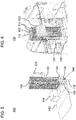
Figuren 7 und 8 zeigen eine schematische räumliche Darstellung bzw. eine schematische Aufsicht eines dritten Ausführungsbeispiels der Vorrichtung 100. Das dritte Ausführungsbeispiels kann eine Weiterbildung des ersten oder zweiten Ausführungsbeispiels sein, wobei überweinstimmende Bezugszeichen gleiche oder austauschbare Merkmale betreffen. - Am oberen Ende 110 des Balgs 102 sind nach innen ragende Griffe 150 angeordnet. Beispielsweise erstrecken sich zwei gegenüberliegende Griffe 150 quer zur Längsrichtung 104 des Balgs 102 ausgehend vom oberen Rahmen des Balgs. Indem in jeder Hand einer der Griffe 150 gefasst wird kann eine in der Wanne 106 stehende Person das obere Ende 110 des Balgs 102 zur Decke 134 heben, wo das obere Ende 110 beispielsweise in der gestreckten Stellung des Balgs 102 lösbar befestigt wird. Nach dem Duschen kann mittels der Griffe 150 eine in der Wanne 106 stehende Person das obere Ende 110 des Balgs 102 absenken in die zusammengefaltete, ungestreckte Stellung des Balgs 102.
- In jedem Ausführungsbeispiel kann der Duschkopf 128 an der Kabinendecke 134 befestigt sein oder über einen flexiblen Schlauch 148 mit dem Tank 122 in Fluidverbindung stehen. Im ungenutzten Zustand können der Schlauch 148 und der Duschkopf 128 in der Wanne 106 verstaut sein.
- Obwohl die Erfindung unter Bezugnahme auf bestimmte Ausführungsbeispiele beschrieben worden ist, ist es für einen Fachmann ersichtlich, dass verschiedene Änderungen vorgenommen werden können und Äquivalente als Ersatz verwendet werden können. Ferner können viele Modifikationen vorgenommen werden, um eine bestimmte Situation oder ein bestimmtes Material an die Lehre der Erfindung anzupassen. Folglich ist die Erfindung nicht auf die offenbarten Ausführungsbeispiele beschränkt, sondern umfasst alle Ausführungsbeispiele, die in den Bereich der beigefügten Patentansprüche fallen.
-
- 100
- Duschvorrichtung
- 102
- Balg
- 104
- Streckbare Längsrichtung des Balgs
- 106
- Wanne
- 108
- Untere Öffnung des Balgs
- 110
- Oberes Ende des Balgs
- 112
- Rand der Wanne
- 114
- Reißverschluss
- 116
- Befestigungsstellen
- 118
- Wasserablauf
- 120
- Auffanggefäß
- 122
- Frischwassertank
- 124
- Zuleitung
- 126
- Pumpe
- 128
- Duschkopf
- 130
- Nutzfahrzeug
- 132
- Fahrerkabine
- 134
- Decke der Fahrerkabine
- 136
- Außenklappe
- 138
- B-Säule der Fahrerkabine
- 140
- Horizontale Querstrebe
- 142
- Boden der Fahrerkabine
- 144
- Ausnehmung am Kabinenboden
- 146
- Frischwasseranschluss
- 148
- Flexibler Schlauch
- 150
- Griff am oberen Ende
Claims (15)
- Duschvorrichtung (100), die in einer Fahrerkabine (132) eines Nutzfahrzeugs (130) eingebaut oder einbaubar ist, wobei die Vorrichtung umfasst:eine Wanne (106), die an einem Boden (142) der Fahrerkabine eingebaut oder einbaubar ist; undeinen wasserundurchlässigen Balg (102), der in vertikaler Richtung (104) streckbar ist, und dessen untere Öffnung (106) gegenüber einem Rand (108) der Wanne (102) zur Leitung von innerhalb des Balgs herablaufendem Wasser in die Wanne angeordnet oder anordenbar ist.
- Vorrichtung nach Anspruch 1, wobei der Balg blickdicht und/oder lichtdurchlässig ist.
- Vorrichtung nach Anspruch 1 oder 2, wobei die untere Öffnung (108) des Balgs (102) am Rand (108) der Wanne (102) befestigt ist, und wobei ein der unteren Öffnung (108) gegenüberliegendes oberes Ende (110) des Balgs (102) beim Übergang von einer ungestreckten Stellung in eine gestreckten Stellung des Balgs entlang der vertikalen Richtung (104) beweglich ist.
- Vorrichtung nach Anspruch 3, wobei das obere Ende (110) des Balgs (102) in der gestreckten Stellung des Balgs lösbar an einer Decke (134) der Fahrerkabine (132) befestigt oder befestigbar ist.
- Vorrichtung nach einem der Ansprüche 1 bis 4, wobei ein der unteren Öffnung (108) gegenüberliegendes oberes Ende (110) des Balgs (102) an einer Decke (134) der Fahrerkabine (132) befestigt ist, und wobei die untere Öffnung (108) des Balgs (102) beim Übergang von einer ungestreckten Stellung in eine gestreckten Stellung des Balgs entlang der vertikalen Richtung (104) beweglich ist.
- Vorrichtung nach Anspruch 5, wobei die untere Öffnung (108) des Balgs (102) in der gestreckten Stellung des Balgs lösbar am Rand (108) der Wanne (102) befestigbar ist.
- Vorrichtung nach einem der Ansprüche 1 bis 6, wobei der Balg (102) einen sich in die vertikale Richtung (104) erstreckenden Reißverschluss (114) umfasst.
- Vorrichtung nach einem der Ansprüche 1 bis 7, wobei die Wanne (106) einen Wasserablauf (118) umfasst, der über eine Außenklappe (136) von außerhalb des Nutzfahrzeugs (132) zugänglich ist.
- Vorrichtung nach einem der Ansprüche 1 bis 8, ferner einen Tank (122) umfassend, der über eine Zuleitung (124) mit einer elektrisch betriebenen Pumpe (126) mit Frischwasser befüllbar ist.
- Vorrichtung nach Anspruch 9, wobei ein Frischwasseranschluss (146) eingangsseitig der Pumpe (126) über eine Außenklappe (136) von außerhalb des Nutzfahrzeugs (132) zugänglich ist.
- Vorrichtung nach Anspruch 9 oder 10, wobei das Frischwasser im Tank (122) und/oder beim Durchströmen der Zuleitung (124) oder der Pumpe (126) beheizbar ist.
- Vorrichtung nach einem der vorhergehenden Ansprüche, wobei zumindest die Wanne (106) in einer Ausnehmung (144) am Boden (142) der Fahrerkabine (132) eingebaut oder einbaubar ist.
- Vorrichtung nach Anspruch 12, wobei die Vorrichtung (100) mit dem Balg (102) in seiner ungestreckten Stellung innerhalb der Ausnehmung (144) am Boden (142) der Fahrerkabine (132) verstaubar ist.
- Vorrichtung nach einem der vorhergehenden Ansprüche, wobei die Vorrichtung (100) hinter einem Fahrersitz in der Fahrerkabine (132) eingebaut oder einbaubar ist.
- Nutzfahrzeug (130) mit einer Fahrerkabine (132), wobei in der Fahrerkabine eine Duschvorrichtung (100) gemäß einem der Ansprüche 1 bis 14 eingebaut ist.
Applications Claiming Priority (2)
| Application Number | Priority Date | Filing Date | Title |
|---|---|---|---|
| DE102016012870 | 2016-10-28 | ||
| DE102017003080.4A DE102017003080B4 (de) | 2016-10-28 | 2017-03-31 | Duschvorrichtung und damit ausgestattetes Nutzfahrzeug |
Publications (2)
| Publication Number | Publication Date |
|---|---|
| EP3315362A1 true EP3315362A1 (de) | 2018-05-02 |
| EP3315362B1 EP3315362B1 (de) | 2020-04-01 |
Family
ID=60138243
Family Applications (1)
| Application Number | Title | Priority Date | Filing Date |
|---|---|---|---|
| EP17196879.5A Active EP3315362B1 (de) | 2016-10-28 | 2017-10-17 | Duschvorrichtung und damit ausgestattetes nutzfahrzeug |
Country Status (1)
| Country | Link |
|---|---|
| EP (1) | EP3315362B1 (de) |
Cited By (1)
| Publication number | Priority date | Publication date | Assignee | Title |
|---|---|---|---|---|
| CN116729277A (zh) * | 2023-07-26 | 2023-09-12 | 东风商用车有限公司 | 一种车载起居室及其汽车 |
Citations (3)
| Publication number | Priority date | Publication date | Assignee | Title |
|---|---|---|---|---|
| DE7826778U1 (de) * | 1978-12-21 | 6670 St Ingbert | Raumsparende, zusammenlegbare Duscheinrichtung zur Verwendung in Fahrzeugen, die Wohn- und Campingzwecken dienen | |
| DE19815880C1 (de) * | 1998-04-08 | 1999-10-07 | Rudolf Pappers | Fahrzeug, insbesondere LKW, mit integrierter Duschzelle |
| DE102006044412A1 (de) | 2005-12-13 | 2007-06-21 | Grammer Ag | Nutzfahrzeugkabine mit Innenraumtür |
Family Cites Families (1)
| Publication number | Priority date | Publication date | Assignee | Title |
|---|---|---|---|---|
| DE8311886U1 (de) * | 1983-04-21 | 1984-01-19 | Parthum, Klaus, 8079 Egweil | Campingfahrzeug |
-
2017
- 2017-10-17 EP EP17196879.5A patent/EP3315362B1/de active Active
Patent Citations (3)
| Publication number | Priority date | Publication date | Assignee | Title |
|---|---|---|---|---|
| DE7826778U1 (de) * | 1978-12-21 | 6670 St Ingbert | Raumsparende, zusammenlegbare Duscheinrichtung zur Verwendung in Fahrzeugen, die Wohn- und Campingzwecken dienen | |
| DE19815880C1 (de) * | 1998-04-08 | 1999-10-07 | Rudolf Pappers | Fahrzeug, insbesondere LKW, mit integrierter Duschzelle |
| DE102006044412A1 (de) | 2005-12-13 | 2007-06-21 | Grammer Ag | Nutzfahrzeugkabine mit Innenraumtür |
Cited By (1)
| Publication number | Priority date | Publication date | Assignee | Title |
|---|---|---|---|---|
| CN116729277A (zh) * | 2023-07-26 | 2023-09-12 | 东风商用车有限公司 | 一种车载起居室及其汽车 |
Also Published As
| Publication number | Publication date |
|---|---|
| EP3315362B1 (de) | 2020-04-01 |
Similar Documents
| Publication | Publication Date | Title |
|---|---|---|
| DE102018124731A1 (de) | Fahrzeugreinigungssystem und Verfahren | |
| EP3772450B1 (de) | Transportfahrrad mit geschlossene kabine und das mit muskelkraft und/oder mittels elektrischem antrieb abtreibbar ist | |
| DE102017003080B4 (de) | Duschvorrichtung und damit ausgestattetes Nutzfahrzeug | |
| DE102014001105B4 (de) | Rollstuhlrampe an einem Fahrzeug, insbesondere an einem Bus, Kassettenbauteil und Fahrzeug mit einer Rollstuhlrampe | |
| EP3315362B1 (de) | Duschvorrichtung und damit ausgestattetes nutzfahrzeug | |
| DE102018001924A1 (de) | Einstiegsvorrichtung für ein Kraftfahrzeug, insbesondere ein Lastkraftfahrzeug | |
| DE10336847B4 (de) | Motorbetriebenes Fahrzeug mit separiertem Wartungsbereich | |
| EP3817954A1 (de) | Vorrichtung zur reinigung von zweirädern | |
| DE3740484A1 (de) | Klappbares waschbecken in einem fahrzeug, insbesondere in einem lkw-fahrerhaus | |
| DE19748894A1 (de) | Großraumfahrzeug | |
| DE19948182A1 (de) | Duscheinrichtung für ein Wohnmobil | |
| DE102004005483B4 (de) | Kraftfahrzeug mit am Dachhimmel ausgebildetem Hohlraum | |
| DE202006005639U1 (de) | Wohnanhänger | |
| WO2007025620A1 (de) | Fahrerkabine für einen lastkraftwagen | |
| DE102019208242B4 (de) | Kraftfahrzeug | |
| DE19815880C1 (de) | Fahrzeug, insbesondere LKW, mit integrierter Duschzelle | |
| DE102014226461A1 (de) | Fahrzeug mit einem Staufach für ein zusammenlegbares Fortbewegungsmittel | |
| LU103349B1 (de) | Expeditionscampingbox | |
| DE202024102998U1 (de) | Mobiles Duschset | |
| DE102010013074A1 (de) | Abdeckung für die Heckklappe | |
| DE10233747B4 (de) | Variabel anbringbares Fahrzeugdach für ein Fahrzeug sowie Fahrzeug mit einem derartigen Fahrzeugdach | |
| DE10242065B4 (de) | Kraftfahrzeug | |
| DE102008045770B4 (de) | Verwandelbare Karosserie eines Kraftfahrzeugs | |
| AT18475U1 (de) | Mobiles duschset | |
| WO2019063698A1 (de) | Lagervorrichtung |
Legal Events
| Date | Code | Title | Description |
|---|---|---|---|
| PUAI | Public reference made under article 153(3) epc to a published international application that has entered the european phase |
Free format text: ORIGINAL CODE: 0009012 |
|
| STAA | Information on the status of an ep patent application or granted ep patent |
Free format text: STATUS: THE APPLICATION HAS BEEN PUBLISHED |
|
| AK | Designated contracting states |
Kind code of ref document: A1 Designated state(s): AL AT BE BG CH CY CZ DE DK EE ES FI FR GB GR HR HU IE IS IT LI LT LU LV MC MK MT NL NO PL PT RO RS SE SI SK SM TR |
|
| AX | Request for extension of the european patent |
Extension state: BA ME |
|
| STAA | Information on the status of an ep patent application or granted ep patent |
Free format text: STATUS: REQUEST FOR EXAMINATION WAS MADE |
|
| 17P | Request for examination filed |
Effective date: 20181102 |
|
| RBV | Designated contracting states (corrected) |
Designated state(s): AL AT BE BG CH CY CZ DE DK EE ES FI FR GB GR HR HU IE IS IT LI LT LU LV MC MK MT NL NO PL PT RO RS SE SI SK SM TR |
|
| STAA | Information on the status of an ep patent application or granted ep patent |
Free format text: STATUS: EXAMINATION IS IN PROGRESS |
|
| 17Q | First examination report despatched |
Effective date: 20190220 |
|
| RAP1 | Party data changed (applicant data changed or rights of an application transferred) |
Owner name: MAN TRUCK & BUS SE |
|
| GRAP | Despatch of communication of intention to grant a patent |
Free format text: ORIGINAL CODE: EPIDOSNIGR1 |
|
| STAA | Information on the status of an ep patent application or granted ep patent |
Free format text: STATUS: GRANT OF PATENT IS INTENDED |
|
| INTG | Intention to grant announced |
Effective date: 20191023 |
|
| GRAJ | Information related to disapproval of communication of intention to grant by the applicant or resumption of examination proceedings by the epo deleted |
Free format text: ORIGINAL CODE: EPIDOSDIGR1 |
|
| STAA | Information on the status of an ep patent application or granted ep patent |
Free format text: STATUS: EXAMINATION IS IN PROGRESS |
|
| GRAR | Information related to intention to grant a patent recorded |
Free format text: ORIGINAL CODE: EPIDOSNIGR71 |
|
| GRAS | Grant fee paid |
Free format text: ORIGINAL CODE: EPIDOSNIGR3 |
|
| STAA | Information on the status of an ep patent application or granted ep patent |
Free format text: STATUS: GRANT OF PATENT IS INTENDED |
|
| GRAA | (expected) grant |
Free format text: ORIGINAL CODE: 0009210 |
|
| STAA | Information on the status of an ep patent application or granted ep patent |
Free format text: STATUS: THE PATENT HAS BEEN GRANTED |
|
| INTC | Intention to grant announced (deleted) | ||
| AK | Designated contracting states |
Kind code of ref document: B1 Designated state(s): AL AT BE BG CH CY CZ DE DK EE ES FI FR GB GR HR HU IE IS IT LI LT LU LV MC MK MT NL NO PL PT RO RS SE SI SK SM TR |
|
| INTG | Intention to grant announced |
Effective date: 20200221 |
|
| REG | Reference to a national code |
Ref country code: GB Ref legal event code: FG4D Free format text: NOT ENGLISH |
|
| REG | Reference to a national code |
Ref country code: CH Ref legal event code: EP Ref country code: AT Ref legal event code: REF Ref document number: 1250959 Country of ref document: AT Kind code of ref document: T Effective date: 20200415 |
|
| REG | Reference to a national code |
Ref country code: DE Ref legal event code: R096 Ref document number: 502017004460 Country of ref document: DE |
|
| REG | Reference to a national code |
Ref country code: IE Ref legal event code: FG4D Free format text: LANGUAGE OF EP DOCUMENT: GERMAN |
|
| REG | Reference to a national code |
Ref country code: NL Ref legal event code: FP |
|
| REG | Reference to a national code |
Ref country code: SE Ref legal event code: TRGR |
|
| PG25 | Lapsed in a contracting state [announced via postgrant information from national office to epo] |
Ref country code: BG Free format text: LAPSE BECAUSE OF FAILURE TO SUBMIT A TRANSLATION OF THE DESCRIPTION OR TO PAY THE FEE WITHIN THE PRESCRIBED TIME-LIMIT Effective date: 20200701 |
|
| REG | Reference to a national code |
Ref country code: LT Ref legal event code: MG4D |
|
| PG25 | Lapsed in a contracting state [announced via postgrant information from national office to epo] |
Ref country code: IS Free format text: LAPSE BECAUSE OF FAILURE TO SUBMIT A TRANSLATION OF THE DESCRIPTION OR TO PAY THE FEE WITHIN THE PRESCRIBED TIME-LIMIT Effective date: 20200801 Ref country code: FI Free format text: LAPSE BECAUSE OF FAILURE TO SUBMIT A TRANSLATION OF THE DESCRIPTION OR TO PAY THE FEE WITHIN THE PRESCRIBED TIME-LIMIT Effective date: 20200401 Ref country code: PT Free format text: LAPSE BECAUSE OF FAILURE TO SUBMIT A TRANSLATION OF THE DESCRIPTION OR TO PAY THE FEE WITHIN THE PRESCRIBED TIME-LIMIT Effective date: 20200817 Ref country code: GR Free format text: LAPSE BECAUSE OF FAILURE TO SUBMIT A TRANSLATION OF THE DESCRIPTION OR TO PAY THE FEE WITHIN THE PRESCRIBED TIME-LIMIT Effective date: 20200702 Ref country code: NO Free format text: LAPSE BECAUSE OF FAILURE TO SUBMIT A TRANSLATION OF THE DESCRIPTION OR TO PAY THE FEE WITHIN THE PRESCRIBED TIME-LIMIT Effective date: 20200701 Ref country code: CZ Free format text: LAPSE BECAUSE OF FAILURE TO SUBMIT A TRANSLATION OF THE DESCRIPTION OR TO PAY THE FEE WITHIN THE PRESCRIBED TIME-LIMIT Effective date: 20200401 Ref country code: LT Free format text: LAPSE BECAUSE OF FAILURE TO SUBMIT A TRANSLATION OF THE DESCRIPTION OR TO PAY THE FEE WITHIN THE PRESCRIBED TIME-LIMIT Effective date: 20200401 |
|
| PG25 | Lapsed in a contracting state [announced via postgrant information from national office to epo] |
Ref country code: RS Free format text: LAPSE BECAUSE OF FAILURE TO SUBMIT A TRANSLATION OF THE DESCRIPTION OR TO PAY THE FEE WITHIN THE PRESCRIBED TIME-LIMIT Effective date: 20200401 Ref country code: HR Free format text: LAPSE BECAUSE OF FAILURE TO SUBMIT A TRANSLATION OF THE DESCRIPTION OR TO PAY THE FEE WITHIN THE PRESCRIBED TIME-LIMIT Effective date: 20200401 Ref country code: LV Free format text: LAPSE BECAUSE OF FAILURE TO SUBMIT A TRANSLATION OF THE DESCRIPTION OR TO PAY THE FEE WITHIN THE PRESCRIBED TIME-LIMIT Effective date: 20200401 |
|
| PG25 | Lapsed in a contracting state [announced via postgrant information from national office to epo] |
Ref country code: AL Free format text: LAPSE BECAUSE OF FAILURE TO SUBMIT A TRANSLATION OF THE DESCRIPTION OR TO PAY THE FEE WITHIN THE PRESCRIBED TIME-LIMIT Effective date: 20200401 |
|
| REG | Reference to a national code |
Ref country code: DE Ref legal event code: R097 Ref document number: 502017004460 Country of ref document: DE |
|
| PG25 | Lapsed in a contracting state [announced via postgrant information from national office to epo] |
Ref country code: EE Free format text: LAPSE BECAUSE OF FAILURE TO SUBMIT A TRANSLATION OF THE DESCRIPTION OR TO PAY THE FEE WITHIN THE PRESCRIBED TIME-LIMIT Effective date: 20200401 Ref country code: SM Free format text: LAPSE BECAUSE OF FAILURE TO SUBMIT A TRANSLATION OF THE DESCRIPTION OR TO PAY THE FEE WITHIN THE PRESCRIBED TIME-LIMIT Effective date: 20200401 Ref country code: DK Free format text: LAPSE BECAUSE OF FAILURE TO SUBMIT A TRANSLATION OF THE DESCRIPTION OR TO PAY THE FEE WITHIN THE PRESCRIBED TIME-LIMIT Effective date: 20200401 Ref country code: RO Free format text: LAPSE BECAUSE OF FAILURE TO SUBMIT A TRANSLATION OF THE DESCRIPTION OR TO PAY THE FEE WITHIN THE PRESCRIBED TIME-LIMIT Effective date: 20200401 Ref country code: ES Free format text: LAPSE BECAUSE OF FAILURE TO SUBMIT A TRANSLATION OF THE DESCRIPTION OR TO PAY THE FEE WITHIN THE PRESCRIBED TIME-LIMIT Effective date: 20200401 |
|
| PLBE | No opposition filed within time limit |
Free format text: ORIGINAL CODE: 0009261 |
|
| STAA | Information on the status of an ep patent application or granted ep patent |
Free format text: STATUS: NO OPPOSITION FILED WITHIN TIME LIMIT |
|
| PG25 | Lapsed in a contracting state [announced via postgrant information from national office to epo] |
Ref country code: SK Free format text: LAPSE BECAUSE OF FAILURE TO SUBMIT A TRANSLATION OF THE DESCRIPTION OR TO PAY THE FEE WITHIN THE PRESCRIBED TIME-LIMIT Effective date: 20200401 Ref country code: PL Free format text: LAPSE BECAUSE OF FAILURE TO SUBMIT A TRANSLATION OF THE DESCRIPTION OR TO PAY THE FEE WITHIN THE PRESCRIBED TIME-LIMIT Effective date: 20200401 |
|
| 26N | No opposition filed |
Effective date: 20210112 |
|
| PG25 | Lapsed in a contracting state [announced via postgrant information from national office to epo] |
Ref country code: SI Free format text: LAPSE BECAUSE OF FAILURE TO SUBMIT A TRANSLATION OF THE DESCRIPTION OR TO PAY THE FEE WITHIN THE PRESCRIBED TIME-LIMIT Effective date: 20200401 |
|
| REG | Reference to a national code |
Ref country code: CH Ref legal event code: PL |
|
| PG25 | Lapsed in a contracting state [announced via postgrant information from national office to epo] |
Ref country code: LU Free format text: LAPSE BECAUSE OF NON-PAYMENT OF DUE FEES Effective date: 20201017 Ref country code: MC Free format text: LAPSE BECAUSE OF FAILURE TO SUBMIT A TRANSLATION OF THE DESCRIPTION OR TO PAY THE FEE WITHIN THE PRESCRIBED TIME-LIMIT Effective date: 20200401 |
|
| REG | Reference to a national code |
Ref country code: BE Ref legal event code: MM Effective date: 20201031 |
|
| PG25 | Lapsed in a contracting state [announced via postgrant information from national office to epo] |
Ref country code: BE Free format text: LAPSE BECAUSE OF NON-PAYMENT OF DUE FEES Effective date: 20201031 Ref country code: CH Free format text: LAPSE BECAUSE OF NON-PAYMENT OF DUE FEES Effective date: 20201031 Ref country code: LI Free format text: LAPSE BECAUSE OF NON-PAYMENT OF DUE FEES Effective date: 20201031 |
|
| PG25 | Lapsed in a contracting state [announced via postgrant information from national office to epo] |
Ref country code: IE Free format text: LAPSE BECAUSE OF NON-PAYMENT OF DUE FEES Effective date: 20201017 |
|
| PG25 | Lapsed in a contracting state [announced via postgrant information from national office to epo] |
Ref country code: TR Free format text: LAPSE BECAUSE OF FAILURE TO SUBMIT A TRANSLATION OF THE DESCRIPTION OR TO PAY THE FEE WITHIN THE PRESCRIBED TIME-LIMIT Effective date: 20200401 Ref country code: MT Free format text: LAPSE BECAUSE OF FAILURE TO SUBMIT A TRANSLATION OF THE DESCRIPTION OR TO PAY THE FEE WITHIN THE PRESCRIBED TIME-LIMIT Effective date: 20200401 Ref country code: CY Free format text: LAPSE BECAUSE OF FAILURE TO SUBMIT A TRANSLATION OF THE DESCRIPTION OR TO PAY THE FEE WITHIN THE PRESCRIBED TIME-LIMIT Effective date: 20200401 |
|
| GBPC | Gb: european patent ceased through non-payment of renewal fee |
Effective date: 20211017 |
|
| PG25 | Lapsed in a contracting state [announced via postgrant information from national office to epo] |
Ref country code: MK Free format text: LAPSE BECAUSE OF FAILURE TO SUBMIT A TRANSLATION OF THE DESCRIPTION OR TO PAY THE FEE WITHIN THE PRESCRIBED TIME-LIMIT Effective date: 20200401 |
|
| PG25 | Lapsed in a contracting state [announced via postgrant information from national office to epo] |
Ref country code: GB Free format text: LAPSE BECAUSE OF NON-PAYMENT OF DUE FEES Effective date: 20211017 |
|
| REG | Reference to a national code |
Ref country code: AT Ref legal event code: MM01 Ref document number: 1250959 Country of ref document: AT Kind code of ref document: T Effective date: 20221017 |
|
| PG25 | Lapsed in a contracting state [announced via postgrant information from national office to epo] |
Ref country code: AT Free format text: LAPSE BECAUSE OF NON-PAYMENT OF DUE FEES Effective date: 20221017 |
|
| PGFP | Annual fee paid to national office [announced via postgrant information from national office to epo] |
Ref country code: NL Payment date: 20251024 Year of fee payment: 9 |
|
| PGFP | Annual fee paid to national office [announced via postgrant information from national office to epo] |
Ref country code: DE Payment date: 20251028 Year of fee payment: 9 |
|
| PGFP | Annual fee paid to national office [announced via postgrant information from national office to epo] |
Ref country code: IT Payment date: 20251022 Year of fee payment: 9 |
|
| PGFP | Annual fee paid to national office [announced via postgrant information from national office to epo] |
Ref country code: FR Payment date: 20251027 Year of fee payment: 9 |
|
| PGFP | Annual fee paid to national office [announced via postgrant information from national office to epo] |
Ref country code: SE Payment date: 20251024 Year of fee payment: 9 |