EP3315262A1 - Outil manuel comprenant un moteur à combustion - Google Patents
Outil manuel comprenant un moteur à combustion Download PDFInfo
- Publication number
- EP3315262A1 EP3315262A1 EP16400048.1A EP16400048A EP3315262A1 EP 3315262 A1 EP3315262 A1 EP 3315262A1 EP 16400048 A EP16400048 A EP 16400048A EP 3315262 A1 EP3315262 A1 EP 3315262A1
- Authority
- EP
- European Patent Office
- Prior art keywords
- choke
- actuating
- lever
- guide
- starting
- Prior art date
- Legal status (The legal status is an assumption and is not a legal conclusion. Google has not performed a legal analysis and makes no representation as to the accuracy of the status listed.)
- Granted
Links
- 238000002485 combustion reaction Methods 0.000 title claims abstract description 14
- 230000033001 locomotion Effects 0.000 claims abstract description 53
- 230000008878 coupling Effects 0.000 claims abstract description 32
- 238000010168 coupling process Methods 0.000 claims abstract description 32
- 238000005859 coupling reaction Methods 0.000 claims abstract description 32
- 230000002996 emotional effect Effects 0.000 claims 1
- 230000000903 blocking effect Effects 0.000 description 6
- 238000003780 insertion Methods 0.000 description 2
- 230000037431 insertion Effects 0.000 description 2
- 230000005540 biological transmission Effects 0.000 description 1
- 230000015572 biosynthetic process Effects 0.000 description 1
- 238000013016 damping Methods 0.000 description 1
- 238000006073 displacement reaction Methods 0.000 description 1
- 230000000694 effects Effects 0.000 description 1
- 239000000446 fuel Substances 0.000 description 1
- 238000004519 manufacturing process Methods 0.000 description 1
- 239000000203 mixture Substances 0.000 description 1
Images


Classifications
-
- F—MECHANICAL ENGINEERING; LIGHTING; HEATING; WEAPONS; BLASTING
- F02—COMBUSTION ENGINES; HOT-GAS OR COMBUSTION-PRODUCT ENGINE PLANTS
- F02M—SUPPLYING COMBUSTION ENGINES IN GENERAL WITH COMBUSTIBLE MIXTURES OR CONSTITUENTS THEREOF
- F02M1/00—Carburettors with means for facilitating engine's starting or its idling below operational temperatures
- F02M1/02—Carburettors with means for facilitating engine's starting or its idling below operational temperatures the means to facilitate starting or idling being chokes for enriching fuel-air mixture
-
- F—MECHANICAL ENGINEERING; LIGHTING; HEATING; WEAPONS; BLASTING
- F02—COMBUSTION ENGINES; HOT-GAS OR COMBUSTION-PRODUCT ENGINE PLANTS
- F02M—SUPPLYING COMBUSTION ENGINES IN GENERAL WITH COMBUSTIBLE MIXTURES OR CONSTITUENTS THEREOF
- F02M9/00—Carburettors having air or fuel-air mixture passage throttling valves other than of butterfly type; Carburettors having fuel-air mixing chambers of variable shape or position
- F02M9/08—Carburettors having air or fuel-air mixture passage throttling valves other than of butterfly type; Carburettors having fuel-air mixing chambers of variable shape or position having throttling valves rotatably mounted in the passage
-
- B—PERFORMING OPERATIONS; TRANSPORTING
- B27—WORKING OR PRESERVING WOOD OR SIMILAR MATERIAL; NAILING OR STAPLING MACHINES IN GENERAL
- B27B—SAWS FOR WOOD OR SIMILAR MATERIAL; COMPONENTS OR ACCESSORIES THEREFOR
- B27B17/00—Chain saws; Equipment therefor
- B27B17/08—Drives or gearings; Devices for swivelling or tilting the chain saw
- B27B17/083—Devices for arresting movement of the saw chain
-
- F—MECHANICAL ENGINEERING; LIGHTING; HEATING; WEAPONS; BLASTING
- F02—COMBUSTION ENGINES; HOT-GAS OR COMBUSTION-PRODUCT ENGINE PLANTS
- F02B—INTERNAL-COMBUSTION PISTON ENGINES; COMBUSTION ENGINES IN GENERAL
- F02B63/00—Adaptations of engines for driving pumps, hand-held tools or electric generators; Portable combinations of engines with engine-driven devices
- F02B63/02—Adaptations of engines for driving pumps, hand-held tools or electric generators; Portable combinations of engines with engine-driven devices for hand-held tools
-
- F—MECHANICAL ENGINEERING; LIGHTING; HEATING; WEAPONS; BLASTING
- F02—COMBUSTION ENGINES; HOT-GAS OR COMBUSTION-PRODUCT ENGINE PLANTS
- F02M—SUPPLYING COMBUSTION ENGINES IN GENERAL WITH COMBUSTIBLE MIXTURES OR CONSTITUENTS THEREOF
- F02M19/00—Details, component parts, or accessories of carburettors, not provided for in, or of interest apart from, the apparatus of groups F02M1/00 - F02M17/00
-
- B—PERFORMING OPERATIONS; TRANSPORTING
- B27—WORKING OR PRESERVING WOOD OR SIMILAR MATERIAL; NAILING OR STAPLING MACHINES IN GENERAL
- B27B—SAWS FOR WOOD OR SIMILAR MATERIAL; COMPONENTS OR ACCESSORIES THEREFOR
- B27B17/00—Chain saws; Equipment therefor
- B27B17/02—Chain saws equipped with guide bar
-
- F—MECHANICAL ENGINEERING; LIGHTING; HEATING; WEAPONS; BLASTING
- F02—COMBUSTION ENGINES; HOT-GAS OR COMBUSTION-PRODUCT ENGINE PLANTS
- F02D—CONTROLLING COMBUSTION ENGINES
- F02D9/00—Controlling engines by throttling air or fuel-and-air induction conduits or exhaust conduits
- F02D9/02—Controlling engines by throttling air or fuel-and-air induction conduits or exhaust conduits concerning induction conduits
- F02D2009/0201—Arrangements; Control features; Details thereof
- F02D2009/0254—Mechanical control linkage between accelerator lever and throttle valve
-
- F—MECHANICAL ENGINEERING; LIGHTING; HEATING; WEAPONS; BLASTING
- F02—COMBUSTION ENGINES; HOT-GAS OR COMBUSTION-PRODUCT ENGINE PLANTS
- F02N—STARTING OF COMBUSTION ENGINES; STARTING AIDS FOR SUCH ENGINES, NOT OTHERWISE PROVIDED FOR
- F02N3/00—Other muscle-operated starting apparatus
- F02N3/02—Other muscle-operated starting apparatus having pull-cords
Definitions
- the invention relates to a hand-held implement of the type specified in the preamble of claim 1.
- a carburetor assembly for a combustion engine in a hand-held implement having a starting device.
- the starting device comprises an operator-actuated mode selector, which is connected via a coupling rod with a choke lever of a choke element.
- the arrangement is such that each position of the mode selector is assigned a position of the choke operating lever and thus a position of the starting device. Based on the position of the mode selector, the operator can therefore easily recognize in which position the starting device is located.
- the choke element In the operating position and the off position, the choke element is usually in the same position. Accordingly, between the operating position and the off position of the actuating element, movement of the actuating element must be possible without the choke operating lever moving. This is done in known systems by positioning the levers to each other.
- the invention has for its object to provide a hand-held implement of the generic type, which allows a flexible arrangement of the actuator. This object is achieved by a hand-held implement with the features of claim 1.
- the operative connection between the actuating element and the choke actuating lever has a relative movement device.
- the relative movement device allows, in at least one position of the choke element, a relative movement of the actuation element relative to the choke actuation lever.
- the position of the pivot axis of the choke actuating lever need not be chosen so that the actuator can move without significant movement of a coupling point on the choke control lever between the operating position and the off position. Rather, the position of the choke lever can be selected largely freely.
- the relative movement of the actuating element relative to the choke actuating lever is made possible via the relative movement device.
- the relative movement device allows, in particular, a relative movement of the coupling element relative to the choke actuating lever and with respect to the choke element.
- a holding device which comprises a stationary on the carburetor housing held guide contour.
- the guide contour holds in at least one starting position of the choke element, the actuating element in the starting position and prevents a relative movement of the actuating element relative to the choke actuating lever from the starting position to the operating position.
- the holding device thereby simultaneously ensures that the position of the actuating element is coupled to the position of the choke actuating lever.
- the actuating element can due to the holding device does not move from the starting position to the operating position with respect to the choke operating lever. This ensures that the actuating element remains in the position for the assigned starting position when the starting device is in the starting position, and can not adjust with respect to the choke operating lever with the aid of the relative movement device.
- a movement of the actuating element relative to the choke operating lever could lead to the choke operating lever being in a starting position, but the actuating element is no longer in the assigned starting position but, for example, in the operating position. This is easily avoided by the holding device.
- the relative movement device allows in the operating position of the choke element relative movement of the actuating element of the starting device relative to the choke actuating lever, so that the choke operating lever is not moved when the actuating element between the operating position and the off position is adjusted.
- the holding device locks the relative movement device in the starting position of the actuating element.
- the holding device causes a movement of the actuating element from the operating position into the at least one starting position causes a movement of the choke actuating lever.
- the movement of the choke actuating lever effects an adjustment of the choke element into the assigned starting position of the choke element.
- the holding device can lock the relative movement device and / or hold the choke element in at least one starting position.
- the Chokeelemerlt always moves with the choke lever.
- the operating position of the choke element is in particular the position in which the choke element releases the cross section of the intake duct.
- a starting position of the choke element is a position in which the choke element partially or almost completely closes the cross section of the intake duct.
- the relative movement device comprises a slot in which a guide element engages.
- the guide element moves during the adjustment of the actuating element from the operating position to the off position from a first position to a second position. Due to the movement of the guide element in the elongated hole, a relative movement of the guide element relative to the choke actuating lever can be made possible in a simple manner. As a result of the movement of the guide element in the oblong hole, a relative movement of the actuating element relative to the choke actuating lever can thus also be made possible.
- the guide element preferably moves from the first position into at least one third position.
- the slot has a first portion and a second portion, which enclose an angle of advantageously more than 45 ° with each other and are connected to each other via a connection region.
- the slot has in particular an angled, preferably an approximately L-shaped configuration.
- a shape deviating from the L-shape of the slot may be advantageous.
- a straight slot can be provided.
- the choke actuating lever and a throttle lever which is connected to a throttle element arranged in the intake passage, engage in locking at least one starting position advantageously in staggered planes with each other.
- the guide element In the second position, the guide element is advantageously in the first section. In the second position, the actuating element is arranged in the off position. In the L-shaped configuration of the oblong hole, the first section is preferably the longer leg of the L. In the third position, the guide element is advantageously located in the second section. In the third position, the actuator is in the starting position. In L-shaped design of the elongated hole, the second portion is preferably the short leg of the L. Particularly preferably, the guide element is in the first position, ie in the operating position of the starting device, in Connection area. In the first position, the actuator is in the operating position. From the connection region, the guide element can be adjusted in the off position in the first section and in an adjustment in a start position in the second section in an adjustment.
- the guide contour advantageously closes at least a portion of the oblong hole in the at least one starting position for the guide element.
- the guide contour thus prevents in a simple manner that the guide element in a section, in particular in the off-position associated portion, can be adjusted.
- the choke actuating lever is likewise adjusted to the assigned starting position. If the choke operating lever is in a start position, the guide contour prevents the guide element from being displaced into the section of the slot assigned to the off position and in particular also into the section of the slot assigned to the operating position. This ensures that the actuating element is in the position assigned to the starting position and the operator can clearly deduce the position of the starting device based on the position of the actuating element.
- the guide contour is formed on a control opening into which the guide member projects.
- the control opening advantageously completely covers the oblong hole in the movement region of the coupling element.
- the range of movement of the coupling element is the region of the oblong hole in which the coupling element can move.
- the guide contour is advantageously formed on a component which is firmly connected to a carburetor housing of the carburetor. It may be advantageous that the guide contour is formed on the carburetor housing itself.
- a simple design results from the formation of the guide contour on a separate component.
- the separate component is preferably made of plastic. This results in a simple structure and a simple production.
- the guide element is formed on the coupling element and the slot on the choke actuating lever.
- the coupling element is designed as a wire bow.
- the guide element is advantageously formed by an angled end of the wire bracket.
- the choke actuating lever is non-rotatably connected to the choke element.
- a sprung mounting of the choke actuating lever relative to the choke element can be provided, which allows a relative movement of the choke actuating lever relative to the choke element in a limited angular range.
- the choke actuating lever and a control part, on which the guide contour is formed advantageously form a slotted guide for the guide element.
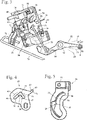
- Fig. 1 shows an embodiment of a hand-held implement a power saw 1.
- the hand-held implement may also be a cut-off, a brushcutter, a blower, a lawnmower or the like.
- the power saw 1 has a housing 2 in which an internal combustion engine 11 is arranged.
- a rear handle 3 which is connected via not shown vibration damping elements with the housing 2, and a handle tube 4, which engages over the housing 2.
- a throttle lever 8 and a throttle lock. 9 pivoted.
- Adjacent to the rear handle 3, an actuating element 10 is also provided, which is designed in the embodiment as a mode selector and which can be pivoted into different positions, as shown schematically by the arrow 71.
- a guide rail 5 is arranged, on which a saw chain 6 is mounted circumferentially.
- the saw chain 6 is the tool of the power saw 1 and is driven by the internal combustion engine 11 to the guide rail 5 circumferentially.
- the internal combustion engine 11 has a carburetor 13, which serves for the supply of fuel / air mixture and which is connected via an intake passage 12 with the engine 11.
- the internal combustion engine 11 is a single-cylinder engine, preferably a mixture-lubricated engine.
- the internal combustion engine 11 is a mixture-lubricated two-stroke engine.
- the internal combustion engine may also be a four-stroke engine, in particular a mixture-lubricated four-stroke engine.
- a hand guard 7 is pivotally mounted, which extends to the saw chain 6 facing side of the handle tube 4 and which is advantageous for triggering a brake device, not shown, for the saw chain 6.
- Fig. 2 shows the design of the carburetor 13 in detail.
- the carburetor 13 has a carburetor housing 14 in which an intake passage section 15 is formed.
- a choke element 16 in the exemplary embodiment a choke flap, is pivotably mounted with a choke shaft 17 about an axis of rotation 18.
- Fig. 2 shows the choke element 16 in an operating position 41, in which the choke element 16, the flow cross section in the intake passage 15 largely releases.
- a spring 40 is arranged, which is formed in the embodiment as a torsion spring, and the choke element 16 in the direction of the in Fig. 2 shown operating position 41 biased.
- a choke actuating lever 19 is arranged on the choke shaft 17.
- the choke lever 19 is rotatably connected to the choke shaft 17.
- a connection between the choke control lever 19th and the choke shaft 17 may be provided, which allows a limited relative movement between the choke operating lever 19 and the choke shaft 17.
- a coupling element 20 in the embodiment, a wire hanger mounted.
- the second end of the coupling element 20 is mounted on the actuating element 10.
- the actuating element 10 is pivotally mounted about a pivot axis 42.
- the actuating element 10 has an actuating portion 68, which advantageously consists of the housing 2 of the power saw 1 (FIG. Fig. 1 protrudes.
- the coupling element 20 is advantageously fixed to a region of the actuating element 10, which is arranged on the side opposite the actuating portion 68 of the pivot axis 42.
- a starting device 21 is provided on the carburetor 13.
- the starting device 21 comprises the actuating element 10, the coupling element 20, the choke actuating lever 19, the choke shaft 17, the choke element 16 and a throttle lever 48 which is non-rotatably connected to a throttle element 52 mounted downstream of the choke element 16 in the intake channel section 15 (FIG. Fig. 3 ) connected is.
- the coupling element 20 is mounted on the choke control lever 19 in a slot 30.
- the slot 30 is formed as part of a relative movement device 28.
- Fig. 2 is the starting device 21 in an operating position 22nd
- the coupling element 20 is in the operating position 22 of the starting device 21 in a first position 32 in the slot 30.
- the coupling element 20 in the slot 30 in both directions, ie in a first section 43 or a second section 44, move.
- the sections 43 and 44 are in Fig. 4 are shown and will be described in more detail below.
- the throttle element 52 is shown schematically.
- the throttle element 52 is a throttle valve.
- the throttle element 52 is pivotally mounted about an axis of rotation 65.
- the throttle lever 48 and the choke lever 19 are in a blocking position 49.
- In the blocking position 49 blocks a blocking portion 50 of the throttle lever 48 a blocking portion 51 of the choke actuating lever 19.
- the choke 16 can not in the direction of arrow 60, ie in a Closing direction of the choke element 16, to be pivoted, without first the throttle lever 48 is pivoted out of the range of movement of the choke actuating lever 19.
- the throttle lever 8 (FIG. Fig. 1 ) are pressed by the operator and thereby the throttle lever 48 are pivoted out of the range of motion.
- the throttle lever 8 acts on a gas actuating rod 71.
- the gas actuation rod 71 acts to actuate the throttle element via an intermediate lever 72 to a not shown, rotatably connected to the throttle element 52 operating lever.
- Fig. 3 are schematically shown the other possible positions of the actuating element 10.
- the starting device 21 By pivoting the actuating portion 68 in the direction of the arrow 57, in Fig. 3 So up, the starting device 21 is moved to an off position 23.
- the off position 23 is designed as a button.
- an ignition of the internal combustion engine 11 is advantageously short-circuited, so that the internal combustion engine 11 is switched off.
- the actuator 10 is advantageously mounted sprung in the direction of the operating position 22 of the starting device 21 and returns after releasing the actuator 10 by the operator back to the operating position 22.
- the actuator 10 is locked in the off position 23 and must be adjusted by the operator back to the operating position 22.
- the operator can the starting device 21 in a second starting position 25, in the embodiment, a cold start position, adjust.
- a first starting position 24 in particular a warm start position
- the operator can pivot the actuating element 22 back in the direction of the arrow 57.
- the operator can actuate the throttle lever 8, whereby a locking described in more detail below between the choke control lever 19 and the throttle lever 48 is released.
- Fig. 4 shows the configuration of the choke operating lever 19 in detail.
- the slot 30 has the first portion 43 and the second portion 44.
- the first portion 34 and the second portion 44 are connected to each other via a connecting portion 45.
- the first section 43 has a longitudinal central axis 46.
- the second section 44 has a longitudinal central axis 47.
- the longitudinal center axes 46 and 47 close to each other at an angle ⁇ , which is advantageously greater than 45 °.
- the angle ⁇ is about 90 °.
- the portion 43 is formed longer than the second portion 44.
- the slot 30 forms in the embodiment, a relative movement means 28.
- the relative movement means 28 allows a relative movement of the coupling element 20 relative to the slot 30.
- Fig. 14 a variant for the slot 30 is shown.
- the blocking portion 51 is formed on a nose 69 of the choke operating lever 19.
- a contact contour 62 is formed, whose function will be described in more detail below.
- Fig. 3 shows a control part 54 set.
- the control part 54 is fixed to the carburetor housing 14 via a fastening screw 56.
- the fastening screw 56 protrudes through a fastening opening 55 of the control part 54, which in Fig. 5 is shown.
- the control part 54 may be integral with the carburetor housing 14 (FIG. Fig. 3 ) be formed.
- the control part 54 has a control opening 34 which has an approximately C-shaped, approximately arcuate course in the embodiment.
- the coupling element 20 (FIG. Fig.
- the slot 30 and the control opening 34 thereby form a guide slot for a guide element 31 formed on the coupling element 20.
- the guide element 31 is in Fig. 6 shown.
- the guide element 31 projects through the choke actuating lever 19 and the control opening 34 in the exemplary embodiment.
- a ceremoniessungsköntur 35 is formed, which forms a holding device 29.
- the guide contour 35 is held in place on the carburetor housing 14 via the fastening screw 56.
- the guide contour 35 can not move relative to the carburetor housing 14 during operation.
- the holding device 29 is formed on a survey 38 on the control part 54.
- the elevation 38 has a recess 39, in which the elevation 38 is formed less high.
- the survey 38 can be completely eliminated.
- the recess 39 is arranged in the region in which the throttle lever 48 is in the operating position 22 ( Fig. 3 ).
- the recess 39 prevents even in unfavorable tolerance position that the throttle lever 48 ( Fig. 3 ) can come into contact with the control part 54.
- the throttle lever 48 is fixed against rotation on a throttle shaft 53.
- the throttle element 52 in the embodiment, a throttle valve fixed.
- a throttle actuating lever 59 is arranged at the opposite end of the throttle lever 48.
- the throttle shaft 53 At the opposite end of the throttle lever 48, the throttle shaft 53, a throttle actuating lever 59 is arranged.
- a transmission device which controls the actuation movement of the throttle lever 8 (FIG. Fig. 1 ) transmits to the throttle actuating lever 59 and thus to the throttle element 52.
- Fig. 6 also shows, has the coupling element 20 of the embodiment of the guide member 31 adjacent a Sicherurigsabexcellent 67, in which the coupling element 20 is angled relative to the guide member 31.
- the security section 67 engages in operation behind the control part 54 and is located between the control part 54 and the carburetor housing 14. Thus, the coupling element 20 is held on the control part 54.
- FIGS. 7 and 8 show the arrangement of the carburetor 13 ( Fig. 2 In the off position 23, the guide element 31 is located in a second position 33. In the second position 33, the guide element 31 is arranged on the end of the first section 43 of the elongated hole 30 facing away from the connection region 45.
- an actuating cam 66 is formed which, in the off position 23, advantageously short-circuits an ignition device of the internal combustion engine 11.
- the guide member 31 moves in the slot 30.
- the slot 30 is aligned so that when adjusting the actuating element 10 from the operating position 22 in the direction of the output Position 23 gives no adjustment of the choke operating lever 19.
- the choke element 16 is in its operating position 41.
- the choke element 16 releases the flow cross section of the intake channel section 15 for the most part.
- Fig. 8 shows, are the slot 30 and the control port 34 in the embodiment in off position 23 in overlap.
- the control opening 34 covers the range of movement of the coupling element 20 in the slot 30 completely.
- the control opening 34 does not block any area of the oblong hole 30 into which the coupling element 20 can move. From the into the FIGS. 7 and 8 shown off position 23, the actuator 10 can thus be moved back into the operating position 22 and from there further preferably in the first starting position 24, without the movement of the coupling element 20 is obstructed in the slot 30 of the guide contour 35.
- the region of the elongated hole 30, in which the coupling element 20 is located when the actuating element 10 is in the second starting position 25, is not shut off.
- FIGS. 9 and 10 In order to adjust the starting device 21 from the operating position 22 to the second starting position 25, which is advantageously a cold start position, the actuating portion 68 is moved in the direction of the arrow 58, as in FIG Fig. 10 is shown schematically.
- the second starting position 25 is engaged by the throttle lever 8 is actuated, then the actuator 10 is pivoted and then the throttle 8 is released again.
- the throttle lever 48 comes with a portion 64 to rest on the choke control lever 19 and holds the choke lever 19 in the appropriate position.
- the region 64 of the throttle lever 48 bears against a contact contour 63 on the outer circumference of the choke actuating lever 19.
- the throttle lever 48 holds the choke operating lever 19 in the second starting position 25
- Fig. 10 schematically shows, in the second starting position 25, the throttle element 52 is turned on and reduces the free flow cross section in the intake passage 15.
- the choke element 16 is in a second starting position 27, in which the choke element 16 largely closes the cross section of the intake passage section 15.
- the guide member 31 is in the second starting position 25 within the slot 30 approximately in the same position as in the first starting position 24.
- the first start position 24 locks the holding device 29, the connecting portion 45 and the first portion 43 of the elongated hole 30, so that the guide element 31 can not get out of the second section 44 without a movement of the choke operating lever 19.
- FIGS. 11 and 12 show the arrangement of the carburetor 13 in the first start position 24, in the embodiment in a hot start position.
- the arrangement can be placed in the first starting position 24.
- a direct insertion of the first starting position 24 without prior insertion of the second starting position 25 is not possible in the embodiment. However, this can also be provided.
- the choke valve 16 has been pivoted and is in a first starting position 26. In the first start position 26, the choke element 16 closes the flow cross-section in the intake passage 15 partially.
- Fig. 12 shows, in the first start position 24 of the region 64 of the throttle lever 48 to the first abutment contour 62 of the choke actuating lever 19 at.
- the guide member 31 is located in the second portion 44 of the slot 30.
- Wie Fig. 12 shows, the control port 34 is only partially in overlap with the slot 30.
- the connecting portion 45 is largely hidden by the control part 54.
- the guide contour 35 prevents the guide element 31 from entering the connection region 45 and from there into the first section 43 of the oblong hole 30, as long as the choke actuation lever 19 is arranged in the first start position 24. This prevents that the actuating element 10 can be adjusted to a position which is assigned to the operating position 22 or the off position 23.
- the guide contour 35 holds the actuating element 10 in the position assigned to the first starting position 24.
- the guide contour 35 prevents a relative movement of the actuating element 10 relative to the choke actuating lever 19 from the first starting position 24 into the operating position 22.
- the guide element 31 is located in a third position 36 in the second section 44, which in the exemplary embodiment is approximately in the middle of the second section 44 located.
- the operator must either release gas to release the first starting position 24, ie the throttle lever 8 (FIG. Fig. 1 ) and pivot, or with an increased force in the direction of the arrow 57 (FIG. Fig. 10 ) against the actuating element 10, so that the area 64 of the throttle lever 48 elastically deformed and the latch between choke control lever 19 and throttle lever 48 is released.
- the Releasing the first starting position 24 is possible in the embodiment due to the elasticity of the throttle lever 48.
- the throttle lever 48 is preferably made of plastic.
- the first starting position 24 could also be achieved by lateral displacement in the direction of the longitudinal axis of the choke shaft 17 (FIG. Fig. 6 ) are solved.
- FIGS. 13 and 14 show an embodiment of a choke operating lever 19 '. Identical reference characters indicate corresponding elements in both embodiments.
- the choke operating lever 19 ' differs from the choke operating lever 19 in the design of the elongated hole 30.
- the choke actuating lever 19' has a slot 30 ', which also has a first portion 43, a second portion 44' and a connecting portion 45.
- the sections 43 and 44 ' extend at an angle ⁇ ' to each other which is greater than 45 °.
- an angle ⁇ 'of slightly more than 90 ° is provided.
- the second portion 44 ' has on the side at which the guide member 31 abuts in the first starting position 24, a recess 70, which serves to compensate for tolerances.
- the guide element 31 is in a fourth position 37, as in Fig. 14 is shown schematically.
- the guide element 31 is located at the end of the second section 44 'facing away from the connection region 45.
- the guide element 31 is in a first position 32 in the connecting region 45.
- the guide element 31 is in the off position 23 in a second position 33, in which the guide member 31 at the end facing away from the connecting portion 45 of the first section 43 is arranged.
Priority Applications (3)
| Application Number | Priority Date | Filing Date | Title |
|---|---|---|---|
| EP16400048.1A EP3315262B1 (fr) | 2016-10-31 | 2016-10-31 | Outil manuel comprenant un moteur à combustion |
| US15/728,856 US10215131B2 (en) | 2016-10-31 | 2017-10-10 | Hand-guided power tool with an internal combustion engine |
| CN201711043678.8A CN108019298B (zh) | 2016-10-31 | 2017-10-31 | 带有内燃机的手持式工作器械 |
Applications Claiming Priority (1)
| Application Number | Priority Date | Filing Date | Title |
|---|---|---|---|
| EP16400048.1A EP3315262B1 (fr) | 2016-10-31 | 2016-10-31 | Outil manuel comprenant un moteur à combustion |
Publications (2)
| Publication Number | Publication Date |
|---|---|
| EP3315262A1 true EP3315262A1 (fr) | 2018-05-02 |
| EP3315262B1 EP3315262B1 (fr) | 2019-09-25 |
Family
ID=57326341
Family Applications (1)
| Application Number | Title | Priority Date | Filing Date |
|---|---|---|---|
| EP16400048.1A Active EP3315262B1 (fr) | 2016-10-31 | 2016-10-31 | Outil manuel comprenant un moteur à combustion |
Country Status (3)
| Country | Link |
|---|---|
| US (1) | US10215131B2 (fr) |
| EP (1) | EP3315262B1 (fr) |
| CN (1) | CN108019298B (fr) |
Families Citing this family (1)
| Publication number | Priority date | Publication date | Assignee | Title |
|---|---|---|---|---|
| US11499506B2 (en) * | 2019-03-05 | 2022-11-15 | Honda Motor Co., Ltd. | Opening/closing mechanism of intake member |
Citations (4)
| Publication number | Priority date | Publication date | Assignee | Title |
|---|---|---|---|---|
| US4113808A (en) * | 1977-03-24 | 1978-09-12 | Outboard Marine Corporation | Carburetor having an automatic choke |
| US20040035394A1 (en) * | 2002-08-22 | 2004-02-26 | Andreas Stihl Ag & Co. Kg | Operating mechanism |
| DE102010009915A1 (de) * | 2009-03-21 | 2010-09-23 | Andreas Stihl Ag & Co. Kg | Vergaseranordnung |
| DE102010009015A1 (de) | 2010-02-24 | 2011-08-25 | OSRAM Opto Semiconductors GmbH, 93055 | Verfahren zum Herstellen einer Mehrzahl von optoelektronischen Halbleiterchips |
Family Cites Families (7)
| Publication number | Priority date | Publication date | Assignee | Title |
|---|---|---|---|---|
| US5078111A (en) * | 1991-05-03 | 1992-01-07 | Ford Motor Company | Variable ratio throttle linkage |
| KR20020029955A (ko) * | 2000-10-16 | 2002-04-22 | 정주호 | 변속에러 방지기능을 가지는 스로틀바디 어셈블리 |
| US7275508B2 (en) * | 2004-09-27 | 2007-10-02 | Walbro Engine Management, L.L.C. | Combustion engine pull-starter |
| US8511286B2 (en) * | 2009-08-03 | 2013-08-20 | Bernardo J. Herzer | Carburetor arrangement |
| US8695952B2 (en) * | 2010-12-28 | 2014-04-15 | Usa Zama Inc. | Carburetor with one piece choke valve and shaft assembly |
| US9429107B2 (en) * | 2013-02-22 | 2016-08-30 | Briggs & Stratton Corporation | Solenoid autochoke for an engine |
| US9074535B1 (en) * | 2013-12-19 | 2015-07-07 | Kohler Co. | Integrated engine control apparatus and method of operating same |
-
2016
- 2016-10-31 EP EP16400048.1A patent/EP3315262B1/fr active Active
-
2017
- 2017-10-10 US US15/728,856 patent/US10215131B2/en active Active
- 2017-10-31 CN CN201711043678.8A patent/CN108019298B/zh active Active
Patent Citations (4)
| Publication number | Priority date | Publication date | Assignee | Title |
|---|---|---|---|---|
| US4113808A (en) * | 1977-03-24 | 1978-09-12 | Outboard Marine Corporation | Carburetor having an automatic choke |
| US20040035394A1 (en) * | 2002-08-22 | 2004-02-26 | Andreas Stihl Ag & Co. Kg | Operating mechanism |
| DE102010009915A1 (de) * | 2009-03-21 | 2010-09-23 | Andreas Stihl Ag & Co. Kg | Vergaseranordnung |
| DE102010009015A1 (de) | 2010-02-24 | 2011-08-25 | OSRAM Opto Semiconductors GmbH, 93055 | Verfahren zum Herstellen einer Mehrzahl von optoelektronischen Halbleiterchips |
Also Published As
| Publication number | Publication date |
|---|---|
| CN108019298A (zh) | 2018-05-11 |
| EP3315262B1 (fr) | 2019-09-25 |
| US10215131B2 (en) | 2019-02-26 |
| US20180119647A1 (en) | 2018-05-03 |
| CN108019298B (zh) | 2021-05-07 |
Similar Documents
| Publication | Publication Date | Title |
|---|---|---|
| DE102005039926B4 (de) | Vergaser | |
| DE102010009915B4 (de) | Vergaseranordnung | |
| DE4117554B4 (de) | Vergaser für eine Brennkraftmaschine, insbesondere einer Motorsäge | |
| EP2808529B1 (fr) | Appareil de travail manuel doté d'un moteur à combustion interne | |
| DE102014114968B4 (de) | Regelvorrichtung für eine Verbrennungskraftmaschine | |
| DE2706389C2 (fr) | ||
| DE602005003605T2 (de) | Zündsystem für tragbare kraftangetriebene Geräte | |
| DE102011105159B4 (de) | Handgeführtes Arbeitsgerät | |
| DE10145293B4 (de) | Vergaseranordnung | |
| DE102009014347B4 (de) | Vergaseranordnung | |
| DE102007021633B4 (de) | Handgeführtes Arbeitsgerät | |
| DE102011086141B4 (de) | Startautomatikvorrichtung | |
| EP2820284B1 (fr) | Vanne mélangeuse d'un moteur à combustion interne | |
| DE102004009180B4 (de) | Handgeführtes Arbeitsgerät | |
| EP3315262B1 (fr) | Outil manuel comprenant un moteur à combustion | |
| DE102013009668B4 (de) | Verbrennungsmotor mit einer Starteinrichtung | |
| DE4006419A1 (de) | Einrichtung mit einem stellglied | |
| DE10238364A1 (de) | Betätigungsvorrichtung | |
| DE10332241A1 (de) | Handgeführtes Arbeitsgerät | |
| EP3315273B1 (fr) | Appareil de travail portatif | |
| DE10126471B4 (de) | Antriebseinrichtung | |
| DE2439441B2 (de) | Vergaser für Brennkraftmaschinen mit einer Startvorrichtung | |
| DE10208051B4 (de) | Membranvergaser für einen mit Spülvorlage arbeitenden Verbrennungsmotor | |
| EP2441945B1 (fr) | Carburateur | |
| DE202009000831U1 (de) | Vergasereinheit für ein Motorgerät |
Legal Events
| Date | Code | Title | Description |
|---|---|---|---|
| PUAI | Public reference made under article 153(3) epc to a published international application that has entered the european phase |
Free format text: ORIGINAL CODE: 0009012 |
|
| STAA | Information on the status of an ep patent application or granted ep patent |
Free format text: STATUS: THE APPLICATION HAS BEEN PUBLISHED |
|
| AK | Designated contracting states |
Kind code of ref document: A1 Designated state(s): AL AT BE BG CH CY CZ DE DK EE ES FI FR GB GR HR HU IE IS IT LI LT LU LV MC MK MT NL NO PL PT RO RS SE SI SK SM TR |
|
| AX | Request for extension of the european patent |
Extension state: BA ME |
|
| STAA | Information on the status of an ep patent application or granted ep patent |
Free format text: STATUS: REQUEST FOR EXAMINATION WAS MADE |
|
| 17P | Request for examination filed |
Effective date: 20181011 |
|
| RBV | Designated contracting states (corrected) |
Designated state(s): AL AT BE BG CH CY CZ DE DK EE ES FI FR GB GR HR HU IE IS IT LI LT LU LV MC MK MT NL NO PL PT RO RS SE SI SK SM TR |
|
| GRAP | Despatch of communication of intention to grant a patent |
Free format text: ORIGINAL CODE: EPIDOSNIGR1 |
|
| STAA | Information on the status of an ep patent application or granted ep patent |
Free format text: STATUS: GRANT OF PATENT IS INTENDED |
|
| RIC1 | Information provided on ipc code assigned before grant |
Ipc: B25F 5/00 20060101AFI20190403BHEP Ipc: F02B 63/02 20060101ALI20190403BHEP Ipc: F02M 1/02 20060101ALI20190403BHEP |
|
| INTG | Intention to grant announced |
Effective date: 20190424 |
|
| GRAS | Grant fee paid |
Free format text: ORIGINAL CODE: EPIDOSNIGR3 |
|
| GRAA | (expected) grant |
Free format text: ORIGINAL CODE: 0009210 |
|
| STAA | Information on the status of an ep patent application or granted ep patent |
Free format text: STATUS: THE PATENT HAS BEEN GRANTED |
|
| AK | Designated contracting states |
Kind code of ref document: B1 Designated state(s): AL AT BE BG CH CY CZ DE DK EE ES FI FR GB GR HR HU IE IS IT LI LT LU LV MC MK MT NL NO PL PT RO RS SE SI SK SM TR |
|
| REG | Reference to a national code |
Ref country code: GB Ref legal event code: FG4D Free format text: NOT ENGLISH |
|
| REG | Reference to a national code |
Ref country code: CH Ref legal event code: EP |
|
| REG | Reference to a national code |
Ref country code: DE Ref legal event code: R096 Ref document number: 502016006781 Country of ref document: DE |
|
| REG | Reference to a national code |
Ref country code: AT Ref legal event code: REF Ref document number: 1183356 Country of ref document: AT Kind code of ref document: T Effective date: 20191015 |
|
| REG | Reference to a national code |
Ref country code: IE Ref legal event code: FG4D Free format text: LANGUAGE OF EP DOCUMENT: GERMAN |
|
| REG | Reference to a national code |
Ref country code: NL Ref legal event code: MP Effective date: 20190925 |
|
| PG25 | Lapsed in a contracting state [announced via postgrant information from national office to epo] |
Ref country code: FI Free format text: LAPSE BECAUSE OF FAILURE TO SUBMIT A TRANSLATION OF THE DESCRIPTION OR TO PAY THE FEE WITHIN THE PRESCRIBED TIME-LIMIT Effective date: 20190925 Ref country code: BG Free format text: LAPSE BECAUSE OF FAILURE TO SUBMIT A TRANSLATION OF THE DESCRIPTION OR TO PAY THE FEE WITHIN THE PRESCRIBED TIME-LIMIT Effective date: 20191225 Ref country code: NO Free format text: LAPSE BECAUSE OF FAILURE TO SUBMIT A TRANSLATION OF THE DESCRIPTION OR TO PAY THE FEE WITHIN THE PRESCRIBED TIME-LIMIT Effective date: 20191225 Ref country code: SE Free format text: LAPSE BECAUSE OF FAILURE TO SUBMIT A TRANSLATION OF THE DESCRIPTION OR TO PAY THE FEE WITHIN THE PRESCRIBED TIME-LIMIT Effective date: 20190925 Ref country code: HR Free format text: LAPSE BECAUSE OF FAILURE TO SUBMIT A TRANSLATION OF THE DESCRIPTION OR TO PAY THE FEE WITHIN THE PRESCRIBED TIME-LIMIT Effective date: 20190925 Ref country code: LT Free format text: LAPSE BECAUSE OF FAILURE TO SUBMIT A TRANSLATION OF THE DESCRIPTION OR TO PAY THE FEE WITHIN THE PRESCRIBED TIME-LIMIT Effective date: 20190925 |
|
| REG | Reference to a national code |
Ref country code: LT Ref legal event code: MG4D |
|
| PG25 | Lapsed in a contracting state [announced via postgrant information from national office to epo] |
Ref country code: LV Free format text: LAPSE BECAUSE OF FAILURE TO SUBMIT A TRANSLATION OF THE DESCRIPTION OR TO PAY THE FEE WITHIN THE PRESCRIBED TIME-LIMIT Effective date: 20190925 Ref country code: GR Free format text: LAPSE BECAUSE OF FAILURE TO SUBMIT A TRANSLATION OF THE DESCRIPTION OR TO PAY THE FEE WITHIN THE PRESCRIBED TIME-LIMIT Effective date: 20191226 Ref country code: RS Free format text: LAPSE BECAUSE OF FAILURE TO SUBMIT A TRANSLATION OF THE DESCRIPTION OR TO PAY THE FEE WITHIN THE PRESCRIBED TIME-LIMIT Effective date: 20190925 |
|
| PG25 | Lapsed in a contracting state [announced via postgrant information from national office to epo] |
Ref country code: RO Free format text: LAPSE BECAUSE OF FAILURE TO SUBMIT A TRANSLATION OF THE DESCRIPTION OR TO PAY THE FEE WITHIN THE PRESCRIBED TIME-LIMIT Effective date: 20190925 Ref country code: NL Free format text: LAPSE BECAUSE OF FAILURE TO SUBMIT A TRANSLATION OF THE DESCRIPTION OR TO PAY THE FEE WITHIN THE PRESCRIBED TIME-LIMIT Effective date: 20190925 Ref country code: PL Free format text: LAPSE BECAUSE OF FAILURE TO SUBMIT A TRANSLATION OF THE DESCRIPTION OR TO PAY THE FEE WITHIN THE PRESCRIBED TIME-LIMIT Effective date: 20190925 Ref country code: PT Free format text: LAPSE BECAUSE OF FAILURE TO SUBMIT A TRANSLATION OF THE DESCRIPTION OR TO PAY THE FEE WITHIN THE PRESCRIBED TIME-LIMIT Effective date: 20200127 Ref country code: ES Free format text: LAPSE BECAUSE OF FAILURE TO SUBMIT A TRANSLATION OF THE DESCRIPTION OR TO PAY THE FEE WITHIN THE PRESCRIBED TIME-LIMIT Effective date: 20190925 Ref country code: AL Free format text: LAPSE BECAUSE OF FAILURE TO SUBMIT A TRANSLATION OF THE DESCRIPTION OR TO PAY THE FEE WITHIN THE PRESCRIBED TIME-LIMIT Effective date: 20190925 Ref country code: EE Free format text: LAPSE BECAUSE OF FAILURE TO SUBMIT A TRANSLATION OF THE DESCRIPTION OR TO PAY THE FEE WITHIN THE PRESCRIBED TIME-LIMIT Effective date: 20190925 Ref country code: IT Free format text: LAPSE BECAUSE OF FAILURE TO SUBMIT A TRANSLATION OF THE DESCRIPTION OR TO PAY THE FEE WITHIN THE PRESCRIBED TIME-LIMIT Effective date: 20190925 |
|
| PG25 | Lapsed in a contracting state [announced via postgrant information from national office to epo] |
Ref country code: SK Free format text: LAPSE BECAUSE OF FAILURE TO SUBMIT A TRANSLATION OF THE DESCRIPTION OR TO PAY THE FEE WITHIN THE PRESCRIBED TIME-LIMIT Effective date: 20190925 Ref country code: CZ Free format text: LAPSE BECAUSE OF FAILURE TO SUBMIT A TRANSLATION OF THE DESCRIPTION OR TO PAY THE FEE WITHIN THE PRESCRIBED TIME-LIMIT Effective date: 20190925 Ref country code: SM Free format text: LAPSE BECAUSE OF FAILURE TO SUBMIT A TRANSLATION OF THE DESCRIPTION OR TO PAY THE FEE WITHIN THE PRESCRIBED TIME-LIMIT Effective date: 20190925 Ref country code: IS Free format text: LAPSE BECAUSE OF FAILURE TO SUBMIT A TRANSLATION OF THE DESCRIPTION OR TO PAY THE FEE WITHIN THE PRESCRIBED TIME-LIMIT Effective date: 20200224 |
|
| REG | Reference to a national code |
Ref country code: CH Ref legal event code: PL |
|
| REG | Reference to a national code |
Ref country code: DE Ref legal event code: R097 Ref document number: 502016006781 Country of ref document: DE |
|
| PG2D | Information on lapse in contracting state deleted |
Ref country code: IS |
|
| PG25 | Lapsed in a contracting state [announced via postgrant information from national office to epo] |
Ref country code: DK Free format text: LAPSE BECAUSE OF FAILURE TO SUBMIT A TRANSLATION OF THE DESCRIPTION OR TO PAY THE FEE WITHIN THE PRESCRIBED TIME-LIMIT Effective date: 20190925 Ref country code: LU Free format text: LAPSE BECAUSE OF NON-PAYMENT OF DUE FEES Effective date: 20191031 Ref country code: LI Free format text: LAPSE BECAUSE OF NON-PAYMENT OF DUE FEES Effective date: 20191031 Ref country code: CH Free format text: LAPSE BECAUSE OF NON-PAYMENT OF DUE FEES Effective date: 20191031 Ref country code: IS Free format text: LAPSE BECAUSE OF FAILURE TO SUBMIT A TRANSLATION OF THE DESCRIPTION OR TO PAY THE FEE WITHIN THE PRESCRIBED TIME-LIMIT Effective date: 20200126 |
|
| PLBE | No opposition filed within time limit |
Free format text: ORIGINAL CODE: 0009261 |
|
| STAA | Information on the status of an ep patent application or granted ep patent |
Free format text: STATUS: NO OPPOSITION FILED WITHIN TIME LIMIT |
|
| REG | Reference to a national code |
Ref country code: BE Ref legal event code: MM Effective date: 20191031 |
|
| PG25 | Lapsed in a contracting state [announced via postgrant information from national office to epo] |
Ref country code: MC Free format text: LAPSE BECAUSE OF FAILURE TO SUBMIT A TRANSLATION OF THE DESCRIPTION OR TO PAY THE FEE WITHIN THE PRESCRIBED TIME-LIMIT Effective date: 20190925 Ref country code: BE Free format text: LAPSE BECAUSE OF NON-PAYMENT OF DUE FEES Effective date: 20191031 |
|
| 26N | No opposition filed |
Effective date: 20200626 |
|
| PG25 | Lapsed in a contracting state [announced via postgrant information from national office to epo] |
Ref country code: IE Free format text: LAPSE BECAUSE OF NON-PAYMENT OF DUE FEES Effective date: 20191031 |
|
| PG25 | Lapsed in a contracting state [announced via postgrant information from national office to epo] |
Ref country code: SI Free format text: LAPSE BECAUSE OF FAILURE TO SUBMIT A TRANSLATION OF THE DESCRIPTION OR TO PAY THE FEE WITHIN THE PRESCRIBED TIME-LIMIT Effective date: 20190925 |
|
| PG25 | Lapsed in a contracting state [announced via postgrant information from national office to epo] |
Ref country code: CY Free format text: LAPSE BECAUSE OF FAILURE TO SUBMIT A TRANSLATION OF THE DESCRIPTION OR TO PAY THE FEE WITHIN THE PRESCRIBED TIME-LIMIT Effective date: 20190925 |
|
| PG25 | Lapsed in a contracting state [announced via postgrant information from national office to epo] |
Ref country code: MT Free format text: LAPSE BECAUSE OF FAILURE TO SUBMIT A TRANSLATION OF THE DESCRIPTION OR TO PAY THE FEE WITHIN THE PRESCRIBED TIME-LIMIT Effective date: 20190925 Ref country code: HU Free format text: LAPSE BECAUSE OF FAILURE TO SUBMIT A TRANSLATION OF THE DESCRIPTION OR TO PAY THE FEE WITHIN THE PRESCRIBED TIME-LIMIT; INVALID AB INITIO Effective date: 20161031 |
|
| PG25 | Lapsed in a contracting state [announced via postgrant information from national office to epo] |
Ref country code: TR Free format text: LAPSE BECAUSE OF FAILURE TO SUBMIT A TRANSLATION OF THE DESCRIPTION OR TO PAY THE FEE WITHIN THE PRESCRIBED TIME-LIMIT Effective date: 20190925 |
|
| PG25 | Lapsed in a contracting state [announced via postgrant information from national office to epo] |
Ref country code: MK Free format text: LAPSE BECAUSE OF FAILURE TO SUBMIT A TRANSLATION OF THE DESCRIPTION OR TO PAY THE FEE WITHIN THE PRESCRIBED TIME-LIMIT Effective date: 20190925 |
|
| REG | Reference to a national code |
Ref country code: AT Ref legal event code: MM01 Ref document number: 1183356 Country of ref document: AT Kind code of ref document: T Effective date: 20211031 |
|
| PG25 | Lapsed in a contracting state [announced via postgrant information from national office to epo] |
Ref country code: AT Free format text: LAPSE BECAUSE OF NON-PAYMENT OF DUE FEES Effective date: 20211031 |
|
| PGFP | Annual fee paid to national office [announced via postgrant information from national office to epo] |
Ref country code: GB Payment date: 20231024 Year of fee payment: 8 |
|
| PGFP | Annual fee paid to national office [announced via postgrant information from national office to epo] |
Ref country code: FR Payment date: 20231026 Year of fee payment: 8 Ref country code: DE Payment date: 20231027 Year of fee payment: 8 |