EP3315201B2 - Hackrotor für eine zerkleinerungsmaschine - Google Patents
Hackrotor für eine zerkleinerungsmaschine Download PDFInfo
- Publication number
- EP3315201B2 EP3315201B2 EP17196781.3A EP17196781A EP3315201B2 EP 3315201 B2 EP3315201 B2 EP 3315201B2 EP 17196781 A EP17196781 A EP 17196781A EP 3315201 B2 EP3315201 B2 EP 3315201B2
- Authority
- EP
- European Patent Office
- Prior art keywords
- tool
- chipping
- rotor
- chipping rotor
- knife blade
- Prior art date
- Legal status (The legal status is an assumption and is not a legal conclusion. Google has not performed a legal analysis and makes no representation as to the accuracy of the status listed.)
- Active
Links
Images


Classifications
-
- B—PERFORMING OPERATIONS; TRANSPORTING
- B02—CRUSHING, PULVERISING, OR DISINTEGRATING; PREPARATORY TREATMENT OF GRAIN FOR MILLING
- B02C—CRUSHING, PULVERISING, OR DISINTEGRATING IN GENERAL; MILLING GRAIN
- B02C18/00—Disintegrating by knives or other cutting or tearing members which chop material into fragments
- B02C18/06—Disintegrating by knives or other cutting or tearing members which chop material into fragments with rotating knives
- B02C18/16—Details
- B02C18/18—Knives; Mountings thereof
- B02C18/182—Disc-shaped knives
- B02C18/184—Disc-shaped knives with peripherally arranged demountable cutting tips or elements
-
- B—PERFORMING OPERATIONS; TRANSPORTING
- B02—CRUSHING, PULVERISING, OR DISINTEGRATING; PREPARATORY TREATMENT OF GRAIN FOR MILLING
- B02C—CRUSHING, PULVERISING, OR DISINTEGRATING IN GENERAL; MILLING GRAIN
- B02C18/00—Disintegrating by knives or other cutting or tearing members which chop material into fragments
- B02C18/06—Disintegrating by knives or other cutting or tearing members which chop material into fragments with rotating knives
- B02C18/14—Disintegrating by knives or other cutting or tearing members which chop material into fragments with rotating knives within horizontal containers
- B02C18/145—Disintegrating by knives or other cutting or tearing members which chop material into fragments with rotating knives within horizontal containers with knives spaced axially and circumferentially on the periphery of a cylindrical rotor unit
-
- B—PERFORMING OPERATIONS; TRANSPORTING
- B02—CRUSHING, PULVERISING, OR DISINTEGRATING; PREPARATORY TREATMENT OF GRAIN FOR MILLING
- B02C—CRUSHING, PULVERISING, OR DISINTEGRATING IN GENERAL; MILLING GRAIN
- B02C18/00—Disintegrating by knives or other cutting or tearing members which chop material into fragments
- B02C18/06—Disintegrating by knives or other cutting or tearing members which chop material into fragments with rotating knives
- B02C18/16—Details
- B02C18/18—Knives; Mountings thereof
- B02C18/186—Axially elongated knives
-
- B—PERFORMING OPERATIONS; TRANSPORTING
- B27—WORKING OR PRESERVING WOOD OR SIMILAR MATERIAL; NAILING OR STAPLING MACHINES IN GENERAL
- B27G—ACCESSORY MACHINES OR APPARATUS FOR WORKING WOOD OR SIMILAR MATERIALS; TOOLS FOR WORKING WOOD OR SIMILAR MATERIALS; SAFETY DEVICES FOR WOOD WORKING MACHINES OR TOOLS
- B27G13/00—Cutter blocks; Other rotary cutting tools
- B27G13/08—Cutter blocks; Other rotary cutting tools in the shape of disc-like members; Wood-milling cutters
- B27G13/10—Securing the cutters, e.g. by clamping collars
-
- B—PERFORMING OPERATIONS; TRANSPORTING
- B27—WORKING OR PRESERVING WOOD OR SIMILAR MATERIAL; NAILING OR STAPLING MACHINES IN GENERAL
- B27L—REMOVING BARK OR VESTIGES OF BRANCHES; SPLITTING WOOD; MANUFACTURE OF VENEER, WOODEN STICKS, WOOD SHAVINGS, WOOD FIBRES OR WOOD POWDER
- B27L11/00—Manufacture of wood shavings, chips, powder, or the like; Tools therefor
- B27L11/005—Tools therefor
Definitions
- the invention relates to a chipping rotor for a shredding machine, wherein the chipping rotor comprises tool holders and wherein an overload-protected tool can be received in the tool holders.
- Known shredding machines feature chipping rotors with a small gap, i.e., a small distance between a chipping knife edge or knife blade and the rotor body.
- the resulting wood chips are correspondingly smaller and have a disadvantageously high ash content during the combustion process.
- chipping rotors increasing the gap to produce larger wood chips is difficult, as the chipping rotor's strength is insufficient and/or adjusting it would be time-consuming.
- Knife body is adjustable by means of at least one clamping screw guided next to or through an elongated hole in the knife body, wherein adjusting or pressure screws which cooperate with the rear end of the knife body for its longitudinal adjustment and support are guided in a cross member carried by at least one clamping plate, characterized in that the cross member is held on the clamping plate or plates via an overload protection device, in particular a connection determining a predetermined breaking point, so that the knife body can give way in the event of an overload when the overload protection device is triggered and the cross member is adjusted.
- an overload protection device in particular a connection determining a predetermined breaking point
- DE 203 10 751 (U1 ) "in the event of an overload, e.g. due to pieces of metal or larger stones in the wood chips", in addition to the upper parts of the two screws forming a predetermined breaking point, the relatively large cross member, the two relatively large pressure screws together with their counter nuts and the relatively long adjusting screw together with the spring expansion ring can detach from the knife drum and, in accordance with their relatively large mass, cause relatively large damage to the chipping machine and/or its surroundings.
- the object of the invention is to provide an improved chipping rotor by means of which larger wood chips or both larger and smaller wood chips can be produced more easily or with little adjustment effort and all clamping means of the knife can be replaced with little wear. effort can be exchanged.
- a chipping rotor having the features of claim 1.
- Advantageous embodiments are the subject of the dependent claims. Accordingly, a chipping rotor is provided in which a knife blade of the tool is adjustable in a particular tangential direction of the chipping rotor in order to adjust the advance of the tool.
- the tangential direction of the chipping rotor can refer to the direction in which the knife blade moves when the chipping rotor rotates. Designs are also conceivable in which the knife blade can be coupled to the remaining structure of the tool in an alternative or additional direction. The knife blade can, for example, be moved in a radial direction away from a central axis of rotation of the chipping rotor.
- the adjustability of the knife blade makes it particularly easy to change the forward grip. This is especially true since knife blades on chipping rotors or tools of this type can already be designed to be replaceable. This makes it easier to further develop existing tools so that the knife blades mounted on them are no longer merely replaceable, but also adjustable or can be mounted on the tool in at least two different positions.
- the knife blade can be secured between a lower and an upper tool holder by means of at least one fastening screw.
- the fastening screw can be directed radially outward relative to the chipping rotor, making it easily accessible and rotatable for changing the knife blade.
- the orientation of the fastening screw can also deviate from a radial direction, as long as the screw head of the fastening screw or a nut interacting with the fastening screw is easily accessible to operating or maintenance personnel from a radially outward direction of the chipping rotor.
- the lower tool holder is mounted/coupled to the chipping rotor from the inside.
- radially inwardly oriented locking devices such as screws and/or nuts can protrude from the tool holder into other structures of the chipping rotor, creating a connection between the chipping rotor and the tool.
- a shear bolt is provided on the knife blade and/or the tool holder to protect against foreign matter. If a certain load is exceeded, the shear bolt can release the coupling it creates between, for example, the tool carrier and other structures of the chipping rotor or between the knife blade and other structures of the tool.
- the knife blade can be secured by means of two fastening screws arranged side by side, particularly in the direction of rotation of the chipping rotor or tool.
- the direction of rotation of the tool can indicate the direction in which the tool provided on the chipping rotor moves during its rotation.
- the knife blade can be particularly easily coupled in a rotationally fixed manner to the tool holders and/or the other structure of the tool.
- the knife blade is adjustable relative to the tool holder by means of at least one adjusting screw.
- the at least one adjusting screw can be oriented in the direction of movement of the knife blade and interact with the knife blade in a region of the knife blade opposite the cutting edge.
- the direction of movement of the knife blade can mean the same direction in which the knife blade is adjustable for adjusting the pre-grip.
- the knife blade has at least one elongated hole and/or at least one recess for receiving the Fastening screw.
- the elongated hole or the particularly elongated recess can be oriented in the direction of movement of the knife blade. This advantageously makes it possible to move a worn and/or adjustable knife blade parallel to the course of the elongated hole or the elongated recess and/or in the direction of movement of the knife blade relative to the tool holders and/or relative to the fastening screw and then to secure it to the tool holders protruding further than before.
- a used or worn knife blade can be positioned for replacement or sharpening and further use, and/or the adjustment of the tool's forward grip, which can be carried out according to the invention, can be carried out.
- the lower tool holder can be coupled to the chipping rotor via at least one tool carrier from the interior of the chipping rotor.
- radially inwardly oriented locking means such as screws and/or nuts can protrude from the tool carrier and/or the tool holder into other structures of the chipping rotor and establish a connection between the chipping rotor and the tool.
- the invention is further directed to a comminution machine with a chipping rotor according to one of claims 1 to 7 and to a tool for a chipping rotor according to one of claims 1 to 7.
- the comminution machine or the tool can comprise any features described herein in connection with the chipping rotor, provided that the features can be combined with the aforementioned devices in a way that is obvious to a person skilled in the art. Repetition of such explanations is therefore omitted.
- Figure 1 shows a perspective view of a chipping rotor 1 according to the invention for a comminution unit, wherein tool holders for holding the tools 10 are provided on the chipping rotor 1.
- the tool holders can be designed to be freely swinging and/or overload-protected.
- Three tools 10 are positioned next to one another in the axial direction of the chipping rotor 1.
- a further three tools 10 are arranged next to one another in the axial direction, offset by approximately 90° in the circumferential direction.
- the tools 10 offset in the circumferential direction can be arranged with a gap to one another or offset in the axial direction, so that the chipping rotor 1 has a knife blade 2 with corresponding cutting edges along its entire or almost its entire axial extent.
- the chipping rotor 1 can comprise, in particular, twelve tools 10, although different numbers are also conceivable.
- the number of tools 10 can furthermore be, in particular, a multiple of two, three and/or four.
- the tools 10 can each be arranged at the same distance from a rotational axis of the chipping rotor 1. It is conceivable that the tools 10 are arranged offset from one another in such a way that access to the inner sides of the tools 10 is possible through the chipping rotor 1. This facilitates any necessary assembly or maintenance work on the inner sides of the tools 10.
- At least one wear protection device 9 can be provided, which protects the chipping rotor 1 or the tools 10 from wear, particularly due to excessive material contact.
- the wear protection device 9 can comprise one or more bodies arranged in front of the cutting edges of the knife blades 2 in the direction of rotation of the chipping rotor 1. It is conceivable that two, in particular identical, components of the wear protection device 9 are provided in front of each cutting edge.
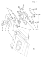
- Figure 2 shows in the left area a perspective view of a tool 10, the individual components of which are shown in the right area of the Figure 2 are shown in exploded view.
- the knife blade 2 is arranged between a lower and an upper tool holder 3, 3' and/or secured by means of at least one fastening screw 4.
- Figure 2 further shows an embodiment in which two fastening screws 4 are provided, arranged next to one another in the direction of rotation of the tool, which can be screwed, for example, into one or more threads of the lower tool holder 3.
- a screw connection with corresponding nuts, not shown, is also conceivable.
- the upper tool holder 3' can comprise a recess 31' into which the heads of the fastening screws 4 can be countersunk, protecting the heads from collisions with the material being cut and thus ensuring a more permanent screw connection.
- the upper tool holder 3' can further comprise a wedge-shaped section and an adjacent cuboid-shaped section.
- the recess 31' can be arranged in the wedge-shaped section.
- the wedge-shaped portion of the upper tool holder 3' may be angled at the same angle as the knife blade 2 that can be locked between the upper and lower tool holders 3', 3.
- the upper and/or lower tool holders 3', 3 may further have the same or almost the same width as the knife blade 2.
- the lower tool holder 3 can also have a greater width than the knife blade 2 and/or the upper tool holder 3'.
- the lower tool holder 3 can have jaws or connections via which it can be coupled to the tool carrier 6.
- the knife blade 2 can also be adjusted by means of at least one adjusting screw 5, in particular relative to the lower tool holder 3.
- the lower tool holder 3 can comprise a corresponding passage for each adjusting screw 5, through which the adjusting screw 5 can be guided.
- the adjusting screw 5 can be brought into direct or indirect contact with the knife blade 2. In the case of indirect contact, at least one nut, a spacer, or another component can be provided between the adjusting screw 5 and the knife blade 2.
- the knife blade 2 can comprise at least one elongated hole or at least one elongated recess 21 in which the fastening screw 4 can be received.
- the recess 21 can be more than half the length of the knife blade 2.
- the fastening screw 4 can be guided through the elongated hole or through the recess 21 and brought into engagement with the lower tool holder 3. By tightening the fastening screws 4, the knife blade 2 can thus be clamped between the lower and upper tool holders 3, 3'.
- the lower tool holder 3 can be coupled to the chipping rotor 1 via at least one tool carrier 6.
- the entire tool 10 can also be coupled to the chipping rotor 1 via the at least one tool carrier 6.
- grooves for receiving the tool carrier 6 can be provided on the chipping rotor 1, for example.
- the lower tool holder 3 can have an L-shaped profile, in which a longer surface provides a storage for the knife blade 2.
- the tray may be provided with passages and/or threaded holes for receiving the fastening screw 4.
- a side arranged perpendicular to the tray may comprise a plurality of passages for receiving screws.
- the side arranged perpendicular to the support can also serve as a stop for the knife blade 2 and/or for the upper tool holder 3'.
- the knife blade 2 and the upper tool holder 3' can extend as far away from the support surface as the side arranged perpendicular to the support.
- the support can also comprise a wedge-shaped section, which is the section of the lower tool holder 3 arranged closest to the cutting edge of the knife blade 2.
- the shear screw 8 shown is provided for securing against foreign matter. This shear screw 8 releases a coupling between the tool 10 and the chipping rotor 1 when a limit load is exceeded due to contact of the tool 10 with corresponding foreign matter.
- Coupling means for connecting the tool carrier 6 to other structures of the chipping rotor 1 can be provided on the lower region of the tool carrier 6.
- the tool carrier 6 can be coupled, in particular screwed, to structures of the chipping rotor 1 from within the chipping rotor 1.
- Figure 3 shows a tool 10 according to the invention, wherein components of the tool 10 are displaced in the tangential direction relative to the tool carrier 6. This increases the distance between the cutting edge of the knife blade 2 and the chopping rotor 1 and thus also increases the advance of the tool 10.
- different bores are provided for adjusting the tool holder 3 relative to the chipping rotor 1.
- the different bores can be used to create multiple cutting areas, which can be finely adjusted using the adjustable knife blades.
- Figure 4 shows the tool 10 according to the invention with, compared to the state of Figure 3 , reduced pre-grip, whereby for this purpose the tool carrier 6 and the lower tool holder 3 are adjusted accordingly in the tangential direction relative to each other.
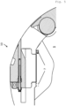
- Figure 5 shows the tool 10 according to the invention, which is connected to the structure of the chopping rotor 1 by means of at least one pressure screw 7.
- a shear screw 8 breaks to protect the device and thus reduces the load on the tool 10. This releases a locking mechanism, whereby parts of the tool 10 are moved relative to the tool carrier 6 to such an extent that the tool has minimal or no pre-engagement.
- the tool 10 is in the Figure 5 shown in a position in which it extends the least far away in a radial direction from the axis of rotation of the chipping rotor 1. In this state, with or without locking or with a broken shear screw 8, the tool 10 can thus be in an innermost position and thus be protected against further damage.
- the chipping rotor 1 can be designed as an open chipping rotor 1.
- the welded construction of the chipping rotor 1 can also have a modular design, and the chipping knife advance can be continuously adjustable, for example, from 20 to 40 mm.
- Each chipping knife or tool 10 can include one or more shear bolts 8 to secure against foreign matter.
- a chipping rotor 1 with a foreign matter protection device can be provided. After the foreign matter protection device has been released, the damaged components can be easily replaced, thus ensuring rapid repair.
- the screw-mounted design of the tool 10 allows for easy replacement of all components. Furthermore, the adjustment of the cutting gap knife or the worn knife blade 2 is possible.
Landscapes
- Engineering & Computer Science (AREA)
- Life Sciences & Earth Sciences (AREA)
- Food Science & Technology (AREA)
- Mechanical Engineering (AREA)
- Wood Science & Technology (AREA)
- Forests & Forestry (AREA)
- Manufacturing & Machinery (AREA)
- Crushing And Pulverization Processes (AREA)
Priority Applications (1)
| Application Number | Priority Date | Filing Date | Title |
|---|---|---|---|
| PL17196781.3T PL3315201T5 (pl) | 2016-10-25 | 2017-10-17 | Rotor tnący do rozdrabniarki |
Applications Claiming Priority (2)
| Application Number | Priority Date | Filing Date | Title |
|---|---|---|---|
| DE102016012743 | 2016-10-25 | ||
| DE102017116005.1A DE102017116005A1 (de) | 2016-10-25 | 2017-07-17 | Hackrotor für eine Zerkleinerungsmaschine |
Publications (3)
| Publication Number | Publication Date |
|---|---|
| EP3315201A1 EP3315201A1 (de) | 2018-05-02 |
| EP3315201B1 EP3315201B1 (de) | 2020-06-24 |
| EP3315201B2 true EP3315201B2 (de) | 2025-05-28 |
Family
ID=60138223
Family Applications (1)
| Application Number | Title | Priority Date | Filing Date |
|---|---|---|---|
| EP17196781.3A Active EP3315201B2 (de) | 2016-10-25 | 2017-10-17 | Hackrotor für eine zerkleinerungsmaschine |
Country Status (2)
| Country | Link |
|---|---|
| EP (1) | EP3315201B2 (pl) |
| PL (1) | PL3315201T5 (pl) |
Families Citing this family (4)
| Publication number | Priority date | Publication date | Assignee | Title |
|---|---|---|---|---|
| IT201900006240A1 (it) * | 2019-04-23 | 2020-10-23 | Seppi M S P A | Machina di trinciatura e taglio di materiale |
| IT202100005765A1 (it) * | 2021-03-11 | 2022-09-11 | Dragone S R L | Trinciatrice per lavorazioni pesanti |
| US11998924B2 (en) | 2022-07-29 | 2024-06-04 | Dragone S.r.l. | Heavy-duty shredder |
| SE547935C2 (sv) * | 2023-05-30 | 2025-12-23 | Linto Ab | Anordning och metod att förse ett skär i härdat stål med en gängning för en ställskruv |
Family Cites Families (7)
| Publication number | Priority date | Publication date | Assignee | Title |
|---|---|---|---|---|
| US3854511A (en) * | 1972-04-24 | 1974-12-17 | Maier Kg Maschf B | Blade holder for steel strip blades |
| AT4232U1 (de) * | 2000-02-01 | 2001-04-25 | Eschlboeck Maschb Gmbh | Messer für holz- und buschhackmaschinen |
| DE20310751U1 (de) * | 2003-07-11 | 2003-12-24 | Eschlböck-Maschinenbau Ges.m.b.H. | Messerhalterung |
| AT501267B8 (de) * | 2005-03-08 | 2007-02-15 | Landmaschb Urch Kg | Messerhalterung |
| DE202008017494U1 (de) * | 2007-04-23 | 2009-11-26 | Steininger, Werner | Werkzeug zum Zerkleinern von Holz |
| AT512247B1 (de) * | 2011-11-25 | 2013-08-15 | Mus Max Gmbh | Halterungsvorrichtung |
| US9375723B2 (en) * | 2013-04-29 | 2016-06-28 | Vermeer Manufacturing Company | Cutter assembly and adjustable cutter for use in comminuting apparatus |
-
2017
- 2017-10-17 EP EP17196781.3A patent/EP3315201B2/de active Active
- 2017-10-17 PL PL17196781.3T patent/PL3315201T5/pl unknown
Also Published As
| Publication number | Publication date |
|---|---|
| PL3315201T5 (pl) | 2025-07-28 |
| EP3315201A1 (de) | 2018-05-02 |
| PL3315201T3 (pl) | 2020-12-28 |
| EP3315201B1 (de) | 2020-06-24 |
Similar Documents
| Publication | Publication Date | Title |
|---|---|---|
| EP1789196B1 (de) | Messerträger für zerkleinerungsvorrichtungen | |
| EP3315201B2 (de) | Hackrotor für eine zerkleinerungsmaschine | |
| EP2233260B1 (de) | Vorrichtung zum Zerkleinern von Holz | |
| WO2007122004A1 (de) | Zerkleinerungsvorrichtung | |
| AT507970B1 (de) | Werkzeug zum zerkleinern von holz | |
| EP2082807B1 (de) | Zerkleinerungsvorrichtung mit gegenläufigen Rotoren | |
| EP2598247B1 (de) | Leitschaufel für eine zerkleinerungsvorrichtung | |
| EP2599553A2 (de) | Werkzeugeinheit und Schneid- oder Stanzwerkzeug für eine Zerkleinerungsvorrichtung, sowie damit ausgerüstete Vorrichtung | |
| EP1960108A1 (de) | Rotor für eine prallmühle | |
| EP2374544B1 (de) | Vorrichtung zum Zerkleinern von kompostierbarem Material | |
| DE102011012663B4 (de) | Messerhalterung zur Befestigung eines Hackmessers | |
| EP3057709A1 (de) | Aufnahmeanordnung eines brechzahnes an einer brechwalze eines brechers | |
| EP1945366A1 (de) | Schneidwerkzeug für zerkleinerungsvorrichtungen | |
| EP2251085A2 (de) | Vorrichtung zum Bearbeiten von Aufgabegut mit einem Rotor-Stator-System | |
| EP2192986B1 (de) | Schlegel für zerkleinerungsvorrichtungen | |
| DE102015005787B4 (de) | Zerkleinerungseinheit für eine Zerkleinerungsvorrichtung zum Zerkleinern von Aufgabegut, insbesondere Messerkorb | |
| DE10026825C2 (de) | Zerkleinerungsvorrichtung | |
| EP2311568B1 (de) | Schneidsatz mit Sicherheitsdistanzringmesser | |
| AT505921B1 (de) | Walzenfräser, insbesondere zum abfräsen des wurzelansatzes von baumstämmen | |
| EP1018414B1 (de) | Messerring-Zerspaner zum Zerspanen von Hackschnitzeln | |
| DE102017116005A1 (de) | Hackrotor für eine Zerkleinerungsmaschine | |
| DE202021003040U1 (de) | Vorrichtung zur Rüstung eines Messerrings eines Messerringzerspaners | |
| DE102006004464B4 (de) | Messerhalterung zur Befestigung eines Hackmessers an einer Messertrommel | |
| DE102014104512A1 (de) | Wirbelring | |
| DE102010054994B4 (de) | Hackmesserwalze für eine Holzhackmaschine |
Legal Events
| Date | Code | Title | Description |
|---|---|---|---|
| PUAI | Public reference made under article 153(3) epc to a published international application that has entered the european phase |
Free format text: ORIGINAL CODE: 0009012 |
|
| STAA | Information on the status of an ep patent application or granted ep patent |
Free format text: STATUS: THE APPLICATION HAS BEEN PUBLISHED |
|
| AK | Designated contracting states |
Kind code of ref document: A1 Designated state(s): AL AT BE BG CH CY CZ DE DK EE ES FI FR GB GR HR HU IE IS IT LI LT LU LV MC MK MT NL NO PL PT RO RS SE SI SK SM TR |
|
| AX | Request for extension of the european patent |
Extension state: BA ME |
|
| STAA | Information on the status of an ep patent application or granted ep patent |
Free format text: STATUS: REQUEST FOR EXAMINATION WAS MADE |
|
| 17P | Request for examination filed |
Effective date: 20181025 |
|
| STAA | Information on the status of an ep patent application or granted ep patent |
Free format text: STATUS: EXAMINATION IS IN PROGRESS |
|
| 17Q | First examination report despatched |
Effective date: 20190218 |
|
| GRAP | Despatch of communication of intention to grant a patent |
Free format text: ORIGINAL CODE: EPIDOSNIGR1 |
|
| STAA | Information on the status of an ep patent application or granted ep patent |
Free format text: STATUS: GRANT OF PATENT IS INTENDED |
|
| INTG | Intention to grant announced |
Effective date: 20200123 |
|
| GRAS | Grant fee paid |
Free format text: ORIGINAL CODE: EPIDOSNIGR3 |
|
| GRAA | (expected) grant |
Free format text: ORIGINAL CODE: 0009210 |
|
| STAA | Information on the status of an ep patent application or granted ep patent |
Free format text: STATUS: THE PATENT HAS BEEN GRANTED |
|
| AK | Designated contracting states |
Kind code of ref document: B1 Designated state(s): AL AT BE BG CH CY CZ DE DK EE ES FI FR GB GR HR HU IE IS IT LI LT LU LV MC MK MT NL NO PL PT RO RS SE SI SK SM TR |
|
| REG | Reference to a national code |
Ref country code: GB Ref legal event code: FG4D Free format text: NOT ENGLISH |
|
| REG | Reference to a national code |
Ref country code: CH Ref legal event code: EP |
|
| REG | Reference to a national code |
Ref country code: DE Ref legal event code: R096 Ref document number: 502017005833 Country of ref document: DE |
|
| REG | Reference to a national code |
Ref country code: AT Ref legal event code: REF Ref document number: 1283358 Country of ref document: AT Kind code of ref document: T Effective date: 20200715 |
|
| REG | Reference to a national code |
Ref country code: IE Ref legal event code: FG4D Free format text: LANGUAGE OF EP DOCUMENT: GERMAN |
|
| REG | Reference to a national code |
Ref country code: CH Ref legal event code: NV Representative=s name: KELLER AND PARTNER PATENTANWAELTE AG, CH |
|
| REG | Reference to a national code |
Ref country code: DK Ref legal event code: T3 Effective date: 20200909 |
|
| REG | Reference to a national code |
Ref country code: SE Ref legal event code: TRGR |
|
| REG | Reference to a national code |
Ref country code: CH Ref legal event code: PFA Owner name: KOMPTECH GMBH, AT Free format text: FORMER OWNER: KOMPTECH GMBH, AT |
|
| REG | Reference to a national code |
Ref country code: NL Ref legal event code: FP |
|
| PG25 | Lapsed in a contracting state [announced via postgrant information from national office to epo] |
Ref country code: FI Free format text: LAPSE BECAUSE OF FAILURE TO SUBMIT A TRANSLATION OF THE DESCRIPTION OR TO PAY THE FEE WITHIN THE PRESCRIBED TIME-LIMIT Effective date: 20200624 Ref country code: LT Free format text: LAPSE BECAUSE OF FAILURE TO SUBMIT A TRANSLATION OF THE DESCRIPTION OR TO PAY THE FEE WITHIN THE PRESCRIBED TIME-LIMIT Effective date: 20200624 Ref country code: NO Free format text: LAPSE BECAUSE OF FAILURE TO SUBMIT A TRANSLATION OF THE DESCRIPTION OR TO PAY THE FEE WITHIN THE PRESCRIBED TIME-LIMIT Effective date: 20200924 Ref country code: GR Free format text: LAPSE BECAUSE OF FAILURE TO SUBMIT A TRANSLATION OF THE DESCRIPTION OR TO PAY THE FEE WITHIN THE PRESCRIBED TIME-LIMIT Effective date: 20200925 |
|
| REG | Reference to a national code |
Ref country code: LT Ref legal event code: MG4D |
|
| PG25 | Lapsed in a contracting state [announced via postgrant information from national office to epo] |
Ref country code: BG Free format text: LAPSE BECAUSE OF FAILURE TO SUBMIT A TRANSLATION OF THE DESCRIPTION OR TO PAY THE FEE WITHIN THE PRESCRIBED TIME-LIMIT Effective date: 20200924 Ref country code: RS Free format text: LAPSE BECAUSE OF FAILURE TO SUBMIT A TRANSLATION OF THE DESCRIPTION OR TO PAY THE FEE WITHIN THE PRESCRIBED TIME-LIMIT Effective date: 20200624 Ref country code: LV Free format text: LAPSE BECAUSE OF FAILURE TO SUBMIT A TRANSLATION OF THE DESCRIPTION OR TO PAY THE FEE WITHIN THE PRESCRIBED TIME-LIMIT Effective date: 20200624 Ref country code: HR Free format text: LAPSE BECAUSE OF FAILURE TO SUBMIT A TRANSLATION OF THE DESCRIPTION OR TO PAY THE FEE WITHIN THE PRESCRIBED TIME-LIMIT Effective date: 20200624 |
|
| PG25 | Lapsed in a contracting state [announced via postgrant information from national office to epo] |
Ref country code: AL Free format text: LAPSE BECAUSE OF FAILURE TO SUBMIT A TRANSLATION OF THE DESCRIPTION OR TO PAY THE FEE WITHIN THE PRESCRIBED TIME-LIMIT Effective date: 20200624 |
|
| PG25 | Lapsed in a contracting state [announced via postgrant information from national office to epo] |
Ref country code: EE Free format text: LAPSE BECAUSE OF FAILURE TO SUBMIT A TRANSLATION OF THE DESCRIPTION OR TO PAY THE FEE WITHIN THE PRESCRIBED TIME-LIMIT Effective date: 20200624 Ref country code: SM Free format text: LAPSE BECAUSE OF FAILURE TO SUBMIT A TRANSLATION OF THE DESCRIPTION OR TO PAY THE FEE WITHIN THE PRESCRIBED TIME-LIMIT Effective date: 20200624 Ref country code: RO Free format text: LAPSE BECAUSE OF FAILURE TO SUBMIT A TRANSLATION OF THE DESCRIPTION OR TO PAY THE FEE WITHIN THE PRESCRIBED TIME-LIMIT Effective date: 20200624 Ref country code: CZ Free format text: LAPSE BECAUSE OF FAILURE TO SUBMIT A TRANSLATION OF THE DESCRIPTION OR TO PAY THE FEE WITHIN THE PRESCRIBED TIME-LIMIT Effective date: 20200624 Ref country code: PT Free format text: LAPSE BECAUSE OF FAILURE TO SUBMIT A TRANSLATION OF THE DESCRIPTION OR TO PAY THE FEE WITHIN THE PRESCRIBED TIME-LIMIT Effective date: 20201026 |
|
| PG25 | Lapsed in a contracting state [announced via postgrant information from national office to epo] |
Ref country code: SK Free format text: LAPSE BECAUSE OF FAILURE TO SUBMIT A TRANSLATION OF THE DESCRIPTION OR TO PAY THE FEE WITHIN THE PRESCRIBED TIME-LIMIT Effective date: 20200624 Ref country code: IS Free format text: LAPSE BECAUSE OF FAILURE TO SUBMIT A TRANSLATION OF THE DESCRIPTION OR TO PAY THE FEE WITHIN THE PRESCRIBED TIME-LIMIT Effective date: 20201024 |
|
| REG | Reference to a national code |
Ref country code: DE Ref legal event code: R026 Ref document number: 502017005833 Country of ref document: DE |
|
| PLBI | Opposition filed |
Free format text: ORIGINAL CODE: 0009260 |
|
| PLAX | Notice of opposition and request to file observation + time limit sent |
Free format text: ORIGINAL CODE: EPIDOSNOBS2 |
|
| REG | Reference to a national code |
Ref country code: ES Ref legal event code: FG2A Ref document number: 2821378 Country of ref document: ES Kind code of ref document: T3 Effective date: 20210426 |
|
| 26 | Opposition filed |
Opponent name: ESCHLBOECK-MASCHINENBAU GESELLSCHAFT M.B.H. Effective date: 20210324 |
|
| PG25 | Lapsed in a contracting state [announced via postgrant information from national office to epo] |
Ref country code: LU Free format text: LAPSE BECAUSE OF NON-PAYMENT OF DUE FEES Effective date: 20201017 Ref country code: MC Free format text: LAPSE BECAUSE OF FAILURE TO SUBMIT A TRANSLATION OF THE DESCRIPTION OR TO PAY THE FEE WITHIN THE PRESCRIBED TIME-LIMIT Effective date: 20200624 |
|
| PLBB | Reply of patent proprietor to notice(s) of opposition received |
Free format text: ORIGINAL CODE: EPIDOSNOBS3 |
|
| PG25 | Lapsed in a contracting state [announced via postgrant information from national office to epo] |
Ref country code: SI Free format text: LAPSE BECAUSE OF FAILURE TO SUBMIT A TRANSLATION OF THE DESCRIPTION OR TO PAY THE FEE WITHIN THE PRESCRIBED TIME-LIMIT Effective date: 20200624 |
|
| PG25 | Lapsed in a contracting state [announced via postgrant information from national office to epo] |
Ref country code: IE Free format text: LAPSE BECAUSE OF NON-PAYMENT OF DUE FEES Effective date: 20201017 |
|
| PG25 | Lapsed in a contracting state [announced via postgrant information from national office to epo] |
Ref country code: TR Free format text: LAPSE BECAUSE OF FAILURE TO SUBMIT A TRANSLATION OF THE DESCRIPTION OR TO PAY THE FEE WITHIN THE PRESCRIBED TIME-LIMIT Effective date: 20200624 Ref country code: MT Free format text: LAPSE BECAUSE OF FAILURE TO SUBMIT A TRANSLATION OF THE DESCRIPTION OR TO PAY THE FEE WITHIN THE PRESCRIBED TIME-LIMIT Effective date: 20200624 Ref country code: CY Free format text: LAPSE BECAUSE OF FAILURE TO SUBMIT A TRANSLATION OF THE DESCRIPTION OR TO PAY THE FEE WITHIN THE PRESCRIBED TIME-LIMIT Effective date: 20200624 |
|
| PG25 | Lapsed in a contracting state [announced via postgrant information from national office to epo] |
Ref country code: MK Free format text: LAPSE BECAUSE OF FAILURE TO SUBMIT A TRANSLATION OF THE DESCRIPTION OR TO PAY THE FEE WITHIN THE PRESCRIBED TIME-LIMIT Effective date: 20200624 |
|
| APAH | Appeal reference modified |
Free format text: ORIGINAL CODE: EPIDOSCREFNO |
|
| APBM | Appeal reference recorded |
Free format text: ORIGINAL CODE: EPIDOSNREFNO |
|
| APBP | Date of receipt of notice of appeal recorded |
Free format text: ORIGINAL CODE: EPIDOSNNOA2O |
|
| APBQ | Date of receipt of statement of grounds of appeal recorded |
Free format text: ORIGINAL CODE: EPIDOSNNOA3O |
|
| APBU | Appeal procedure closed |
Free format text: ORIGINAL CODE: EPIDOSNNOA9O |
|
| PUAH | Patent maintained in amended form |
Free format text: ORIGINAL CODE: 0009272 |
|
| STAA | Information on the status of an ep patent application or granted ep patent |
Free format text: STATUS: PATENT MAINTAINED AS AMENDED |
|
| 27A | Patent maintained in amended form |
Effective date: 20250528 |
|
| AK | Designated contracting states |
Kind code of ref document: B2 Designated state(s): AL AT BE BG CH CY CZ DE DK EE ES FI FR GB GR HR HU IE IS IT LI LT LU LV MC MK MT NL NO PL PT RO RS SE SI SK SM TR |
|
| REG | Reference to a national code |
Ref country code: DE Ref legal event code: R102 Ref document number: 502017005833 Country of ref document: DE |
|
| REG | Reference to a national code |
Ref country code: DK Ref legal event code: T4 Effective date: 20250603 |
|
| REG | Reference to a national code |
Ref country code: NL Ref legal event code: FP |
|
| REG | Reference to a national code |
Ref country code: SE Ref legal event code: RPEO |
|
| PGFP | Annual fee paid to national office [announced via postgrant information from national office to epo] |
Ref country code: PL Payment date: 20250925 Year of fee payment: 9 |
|
| REG | Reference to a national code |
Ref country code: CH Ref legal event code: U11 Free format text: ST27 STATUS EVENT CODE: U-0-0-U10-U11 (AS PROVIDED BY THE NATIONAL OFFICE) Effective date: 20251101 |
|
| PGFP | Annual fee paid to national office [announced via postgrant information from national office to epo] |
Ref country code: NL Payment date: 20251024 Year of fee payment: 9 |
|
| PGFP | Annual fee paid to national office [announced via postgrant information from national office to epo] |
Ref country code: DE Payment date: 20251028 Year of fee payment: 9 |
|
| PGFP | Annual fee paid to national office [announced via postgrant information from national office to epo] |
Ref country code: GB Payment date: 20251024 Year of fee payment: 9 |
|
| PGFP | Annual fee paid to national office [announced via postgrant information from national office to epo] |
Ref country code: AT Payment date: 20251023 Year of fee payment: 9 |
|
| PGFP | Annual fee paid to national office [announced via postgrant information from national office to epo] |
Ref country code: DK Payment date: 20251024 Year of fee payment: 9 Ref country code: IT Payment date: 20251030 Year of fee payment: 9 |
|
| PGFP | Annual fee paid to national office [announced via postgrant information from national office to epo] |
Ref country code: FR Payment date: 20251024 Year of fee payment: 9 |
|
| PGFP | Annual fee paid to national office [announced via postgrant information from national office to epo] |
Ref country code: BE Payment date: 20251024 Year of fee payment: 9 |
|
| PGFP | Annual fee paid to national office [announced via postgrant information from national office to epo] |
Ref country code: SE Payment date: 20251024 Year of fee payment: 9 Ref country code: CH Payment date: 20251101 Year of fee payment: 9 |
|
| PGFP | Annual fee paid to national office [announced via postgrant information from national office to epo] |
Ref country code: ES Payment date: 20251103 Year of fee payment: 9 |