EP3315096B1 - Expandable interbody implant with lateral articulation - Google Patents
Expandable interbody implant with lateral articulation Download PDFInfo
- Publication number
- EP3315096B1 EP3315096B1 EP17198694.6A EP17198694A EP3315096B1 EP 3315096 B1 EP3315096 B1 EP 3315096B1 EP 17198694 A EP17198694 A EP 17198694A EP 3315096 B1 EP3315096 B1 EP 3315096B1
- Authority
- EP
- European Patent Office
- Prior art keywords
- spinal implant
- implant
- piston
- segment
- pistons
- Prior art date
- Legal status (The legal status is an assumption and is not a legal conclusion. Google has not performed a legal analysis and makes no representation as to the accuracy of the status listed.)
- Active
Links
Images












Classifications
-
- A—HUMAN NECESSITIES
- A61—MEDICAL OR VETERINARY SCIENCE; HYGIENE
- A61F—FILTERS IMPLANTABLE INTO BLOOD VESSELS; PROSTHESES; DEVICES PROVIDING PATENCY TO, OR PREVENTING COLLAPSING OF, TUBULAR STRUCTURES OF THE BODY, e.g. STENTS; ORTHOPAEDIC, NURSING OR CONTRACEPTIVE DEVICES; FOMENTATION; TREATMENT OR PROTECTION OF EYES OR EARS; BANDAGES, DRESSINGS OR ABSORBENT PADS; FIRST-AID KITS
- A61F2/00—Filters implantable into blood vessels; Prostheses, i.e. artificial substitutes or replacements for parts of the body; Appliances for connecting them with the body; Devices providing patency to, or preventing collapsing of, tubular structures of the body, e.g. stents
- A61F2/02—Prostheses implantable into the body
- A61F2/30—Joints
- A61F2/44—Joints for the spine, e.g. vertebrae, spinal discs
- A61F2/4455—Joints for the spine, e.g. vertebrae, spinal discs for the fusion of spinal bodies, e.g. intervertebral fusion of adjacent spinal bodies, e.g. fusion cages
-
- A—HUMAN NECESSITIES
- A61—MEDICAL OR VETERINARY SCIENCE; HYGIENE
- A61F—FILTERS IMPLANTABLE INTO BLOOD VESSELS; PROSTHESES; DEVICES PROVIDING PATENCY TO, OR PREVENTING COLLAPSING OF, TUBULAR STRUCTURES OF THE BODY, e.g. STENTS; ORTHOPAEDIC, NURSING OR CONTRACEPTIVE DEVICES; FOMENTATION; TREATMENT OR PROTECTION OF EYES OR EARS; BANDAGES, DRESSINGS OR ABSORBENT PADS; FIRST-AID KITS
- A61F2/00—Filters implantable into blood vessels; Prostheses, i.e. artificial substitutes or replacements for parts of the body; Appliances for connecting them with the body; Devices providing patency to, or preventing collapsing of, tubular structures of the body, e.g. stents
- A61F2/02—Prostheses implantable into the body
- A61F2/30—Joints
- A61F2/44—Joints for the spine, e.g. vertebrae, spinal discs
- A61F2/442—Intervertebral or spinal discs, e.g. resilient
-
- A—HUMAN NECESSITIES
- A61—MEDICAL OR VETERINARY SCIENCE; HYGIENE
- A61F—FILTERS IMPLANTABLE INTO BLOOD VESSELS; PROSTHESES; DEVICES PROVIDING PATENCY TO, OR PREVENTING COLLAPSING OF, TUBULAR STRUCTURES OF THE BODY, e.g. STENTS; ORTHOPAEDIC, NURSING OR CONTRACEPTIVE DEVICES; FOMENTATION; TREATMENT OR PROTECTION OF EYES OR EARS; BANDAGES, DRESSINGS OR ABSORBENT PADS; FIRST-AID KITS
- A61F2/00—Filters implantable into blood vessels; Prostheses, i.e. artificial substitutes or replacements for parts of the body; Appliances for connecting them with the body; Devices providing patency to, or preventing collapsing of, tubular structures of the body, e.g. stents
- A61F2/02—Prostheses implantable into the body
- A61F2/30—Joints
- A61F2/46—Special tools for implanting artificial joints
- A61F2/4603—Special tools for implanting artificial joints for insertion or extraction of endoprosthetic joints or of accessories thereof
- A61F2/4611—Special tools for implanting artificial joints for insertion or extraction of endoprosthetic joints or of accessories thereof of spinal prostheses
-
- A—HUMAN NECESSITIES
- A61—MEDICAL OR VETERINARY SCIENCE; HYGIENE
- A61F—FILTERS IMPLANTABLE INTO BLOOD VESSELS; PROSTHESES; DEVICES PROVIDING PATENCY TO, OR PREVENTING COLLAPSING OF, TUBULAR STRUCTURES OF THE BODY, e.g. STENTS; ORTHOPAEDIC, NURSING OR CONTRACEPTIVE DEVICES; FOMENTATION; TREATMENT OR PROTECTION OF EYES OR EARS; BANDAGES, DRESSINGS OR ABSORBENT PADS; FIRST-AID KITS
- A61F2/00—Filters implantable into blood vessels; Prostheses, i.e. artificial substitutes or replacements for parts of the body; Appliances for connecting them with the body; Devices providing patency to, or preventing collapsing of, tubular structures of the body, e.g. stents
- A61F2/02—Prostheses implantable into the body
- A61F2/48—Operating or control means, e.g. from outside the body, control of sphincters
- A61F2/484—Fluid means, i.e. hydraulic or pneumatic
-
- A—HUMAN NECESSITIES
- A61—MEDICAL OR VETERINARY SCIENCE; HYGIENE
- A61F—FILTERS IMPLANTABLE INTO BLOOD VESSELS; PROSTHESES; DEVICES PROVIDING PATENCY TO, OR PREVENTING COLLAPSING OF, TUBULAR STRUCTURES OF THE BODY, e.g. STENTS; ORTHOPAEDIC, NURSING OR CONTRACEPTIVE DEVICES; FOMENTATION; TREATMENT OR PROTECTION OF EYES OR EARS; BANDAGES, DRESSINGS OR ABSORBENT PADS; FIRST-AID KITS
- A61F2/00—Filters implantable into blood vessels; Prostheses, i.e. artificial substitutes or replacements for parts of the body; Appliances for connecting them with the body; Devices providing patency to, or preventing collapsing of, tubular structures of the body, e.g. stents
- A61F2/02—Prostheses implantable into the body
- A61F2/30—Joints
- A61F2002/30001—Additional features of subject-matter classified in A61F2/28, A61F2/30 and subgroups thereof
- A61F2002/30316—The prosthesis having different structural features at different locations within the same prosthesis; Connections between prosthetic parts; Special structural features of bone or joint prostheses not otherwise provided for
- A61F2002/30329—Connections or couplings between prosthetic parts, e.g. between modular parts; Connecting elements
-
- A—HUMAN NECESSITIES
- A61—MEDICAL OR VETERINARY SCIENCE; HYGIENE
- A61F—FILTERS IMPLANTABLE INTO BLOOD VESSELS; PROSTHESES; DEVICES PROVIDING PATENCY TO, OR PREVENTING COLLAPSING OF, TUBULAR STRUCTURES OF THE BODY, e.g. STENTS; ORTHOPAEDIC, NURSING OR CONTRACEPTIVE DEVICES; FOMENTATION; TREATMENT OR PROTECTION OF EYES OR EARS; BANDAGES, DRESSINGS OR ABSORBENT PADS; FIRST-AID KITS
- A61F2/00—Filters implantable into blood vessels; Prostheses, i.e. artificial substitutes or replacements for parts of the body; Appliances for connecting them with the body; Devices providing patency to, or preventing collapsing of, tubular structures of the body, e.g. stents
- A61F2/02—Prostheses implantable into the body
- A61F2/30—Joints
- A61F2002/30001—Additional features of subject-matter classified in A61F2/28, A61F2/30 and subgroups thereof
- A61F2002/30316—The prosthesis having different structural features at different locations within the same prosthesis; Connections between prosthetic parts; Special structural features of bone or joint prostheses not otherwise provided for
- A61F2002/30535—Special structural features of bone or joint prostheses not otherwise provided for
- A61F2002/30537—Special structural features of bone or joint prostheses not otherwise provided for adjustable
-
- A—HUMAN NECESSITIES
- A61—MEDICAL OR VETERINARY SCIENCE; HYGIENE
- A61F—FILTERS IMPLANTABLE INTO BLOOD VESSELS; PROSTHESES; DEVICES PROVIDING PATENCY TO, OR PREVENTING COLLAPSING OF, TUBULAR STRUCTURES OF THE BODY, e.g. STENTS; ORTHOPAEDIC, NURSING OR CONTRACEPTIVE DEVICES; FOMENTATION; TREATMENT OR PROTECTION OF EYES OR EARS; BANDAGES, DRESSINGS OR ABSORBENT PADS; FIRST-AID KITS
- A61F2/00—Filters implantable into blood vessels; Prostheses, i.e. artificial substitutes or replacements for parts of the body; Appliances for connecting them with the body; Devices providing patency to, or preventing collapsing of, tubular structures of the body, e.g. stents
- A61F2/02—Prostheses implantable into the body
- A61F2/30—Joints
- A61F2002/30001—Additional features of subject-matter classified in A61F2/28, A61F2/30 and subgroups thereof
- A61F2002/30316—The prosthesis having different structural features at different locations within the same prosthesis; Connections between prosthetic parts; Special structural features of bone or joint prostheses not otherwise provided for
- A61F2002/30535—Special structural features of bone or joint prostheses not otherwise provided for
- A61F2002/30537—Special structural features of bone or joint prostheses not otherwise provided for adjustable
- A61F2002/30538—Special structural features of bone or joint prostheses not otherwise provided for adjustable for adjusting angular orientation
-
- A—HUMAN NECESSITIES
- A61—MEDICAL OR VETERINARY SCIENCE; HYGIENE
- A61F—FILTERS IMPLANTABLE INTO BLOOD VESSELS; PROSTHESES; DEVICES PROVIDING PATENCY TO, OR PREVENTING COLLAPSING OF, TUBULAR STRUCTURES OF THE BODY, e.g. STENTS; ORTHOPAEDIC, NURSING OR CONTRACEPTIVE DEVICES; FOMENTATION; TREATMENT OR PROTECTION OF EYES OR EARS; BANDAGES, DRESSINGS OR ABSORBENT PADS; FIRST-AID KITS
- A61F2/00—Filters implantable into blood vessels; Prostheses, i.e. artificial substitutes or replacements for parts of the body; Appliances for connecting them with the body; Devices providing patency to, or preventing collapsing of, tubular structures of the body, e.g. stents
- A61F2/02—Prostheses implantable into the body
- A61F2/30—Joints
- A61F2002/30001—Additional features of subject-matter classified in A61F2/28, A61F2/30 and subgroups thereof
- A61F2002/30316—The prosthesis having different structural features at different locations within the same prosthesis; Connections between prosthetic parts; Special structural features of bone or joint prostheses not otherwise provided for
- A61F2002/30535—Special structural features of bone or joint prostheses not otherwise provided for
- A61F2002/30537—Special structural features of bone or joint prostheses not otherwise provided for adjustable
- A61F2002/30556—Special structural features of bone or joint prostheses not otherwise provided for adjustable for adjusting thickness
-
- A—HUMAN NECESSITIES
- A61—MEDICAL OR VETERINARY SCIENCE; HYGIENE
- A61F—FILTERS IMPLANTABLE INTO BLOOD VESSELS; PROSTHESES; DEVICES PROVIDING PATENCY TO, OR PREVENTING COLLAPSING OF, TUBULAR STRUCTURES OF THE BODY, e.g. STENTS; ORTHOPAEDIC, NURSING OR CONTRACEPTIVE DEVICES; FOMENTATION; TREATMENT OR PROTECTION OF EYES OR EARS; BANDAGES, DRESSINGS OR ABSORBENT PADS; FIRST-AID KITS
- A61F2/00—Filters implantable into blood vessels; Prostheses, i.e. artificial substitutes or replacements for parts of the body; Appliances for connecting them with the body; Devices providing patency to, or preventing collapsing of, tubular structures of the body, e.g. stents
- A61F2/02—Prostheses implantable into the body
- A61F2/30—Joints
- A61F2002/30001—Additional features of subject-matter classified in A61F2/28, A61F2/30 and subgroups thereof
- A61F2002/30316—The prosthesis having different structural features at different locations within the same prosthesis; Connections between prosthetic parts; Special structural features of bone or joint prostheses not otherwise provided for
- A61F2002/30535—Special structural features of bone or joint prostheses not otherwise provided for
- A61F2002/30579—Special structural features of bone or joint prostheses not otherwise provided for with mechanically expandable devices, e.g. fixation devices
-
- A—HUMAN NECESSITIES
- A61—MEDICAL OR VETERINARY SCIENCE; HYGIENE
- A61F—FILTERS IMPLANTABLE INTO BLOOD VESSELS; PROSTHESES; DEVICES PROVIDING PATENCY TO, OR PREVENTING COLLAPSING OF, TUBULAR STRUCTURES OF THE BODY, e.g. STENTS; ORTHOPAEDIC, NURSING OR CONTRACEPTIVE DEVICES; FOMENTATION; TREATMENT OR PROTECTION OF EYES OR EARS; BANDAGES, DRESSINGS OR ABSORBENT PADS; FIRST-AID KITS
- A61F2/00—Filters implantable into blood vessels; Prostheses, i.e. artificial substitutes or replacements for parts of the body; Appliances for connecting them with the body; Devices providing patency to, or preventing collapsing of, tubular structures of the body, e.g. stents
- A61F2/02—Prostheses implantable into the body
- A61F2/30—Joints
- A61F2/46—Special tools for implanting artificial joints
- A61F2/4603—Special tools for implanting artificial joints for insertion or extraction of endoprosthetic joints or of accessories thereof
- A61F2002/4629—Special tools for implanting artificial joints for insertion or extraction of endoprosthetic joints or of accessories thereof connected to the endoprosthesis or implant via a threaded connection
Definitions
- the articulatable portions may include at least three segments, where a first one of the segments is articulatably connected to a second one of the segments, and a third one of the segments is articulatably connected to the second segment, with the second segment being located between the first and third segments.
- the first piston with the larger cross-sectional area may be located on the second segment.
- the spinal implant in accordance with this aspect of the invention preferably includes first and second portions connected together by a first hinge for articulation about the hinge.
- the first hinge may include first and second rigid links each pivotably connected to the first and second portions of the implant.
- the spinal implant may include a third portion connected to the second portion by a second hinge for articulation about the second hinge.
- the second hinge may include third and fourth rigid links each pivotably connected to the second and third portions of the implant.
- the first hinge is configured to allow the first and second portions to articulate into an arrangement such that the longitudinal axes of the first and second portions are coincident with one another.
- the hinge may include a second rigid link pivotably connected to the first and second portions of the implant.
- the second rigid link may have a passageway therein for communicating the hydraulic fluid between the first and second portions of the spinal implant.
- the first and second rigid links may each be pivotably connected to the first and second portions of the implant such that the rigid links are positioned on respective longitudinal sides of the implant.
- the first and second rigid links may each be pivotably connected to the first and second portions of the implant such that the rigid links cross from one longitudinal side of the implant to the other side between each pivotably connected end of the respective link.
- one of the links may have a bent profile.
- the locking system may include a tiered array of upper steps engageable with a tiered array of lower steps at a plurality of discrete positions as the extendable support element expands to the at least one extended configuration.
- the extendable support element may include a piston slidably received within a cylinder coupled to the body.
- the spreader may be insertable into a space defined between the first and second portions in order to spread apart those portions.
- movement of the spreader from the distal end towards the proximal end of the spinal implant may induce the spreading apart of the first and second portions of the implant.
- the spreader may include at least one ramp surface engageable with at least one of the first and second portions of the implant during movement of the spreader from the distal end towards the proximal end, so as to induce the spreading apart of the first and second portions of the implant.
- the spinal implant may be expandable along the longitudinal axis of the spine. That expansion of the spinal implant along the longitudinal axis of the spine may be controlled by the tool.
- a hydraulic fluid may be supplied through the tool to a port at the proximal end of the spinal implant.
- the spinal implant may include a first piston expandable by the hydraulic fluid, which piston may be located on the hinge.
- the spinal implant may include a second piston expandable by the hydraulic fluid, which second piston may be located on one of the first and second portions of the spinal implant.
- the method may further include the step of expanding the implant along the longitudinal axis of the spine.
- the expanding step may be actuated by the tool.
- the expanding step may include supplying a hydraulic fluid to the implant via the tool.
- the hydraulic fluid may flow between the first and second articulatable portions of the implant through the hinge.
- the method may further include the step of expanding first and second pistons disposed on the respective first and second articulatable portions using the hydraulic fluid.
- the expanding step may include applying a pressure to the hydraulic fluid.
- the application of the pressure to the hydraulic fluid may result in the first and second pistons applying respective first and second expansion forces between the first and second vertebral bodies, where the first and second expansion forces are different from one another.
- proximal means closer to the operator/surgeon, and the term “distal” means further away from the operator/surgeon.
- anterior means toward the front of the body or the face, and the term “posterior” means toward the back of the body.
- inferior means toward the front of the body or the face
- posterior means toward the back of the body.
- superior refers to the direction towards the head
- inferior refers to the direction towards the pelvis and feet.
- lateral refers to a direction or movement that is in the transverse plane, which is orthogonal to the longitudinal axis of the spine.
- FIG. 1 illustrates an implant 10 in accordance with one embodiment of the present invention.
- the implant 10 includes two segments articulatable with respect to one another, in the form of a first arm 12 and a second arm 14. Specifically, the first and second arms 12, 14 are connected together by a hinge portion 16.
- the implant 10 is insertable into an intervertebral space in a closed configuration, as illustrated in FIGS. 2A-3A and 4A , and the implant 10 can be expanded laterally within the intervertebral space by articulating the arms 12, 14 apart about the hinge portion 16, as shown in FIGS. 3B and 4B .
- the insertion of the implant 10 into the intervertebral space can be performed by a delivery tool 18 securely attachable to the proximal end 20 of the implant 10 via an anchor located on the implant 10.
- the anchor may be in the form of a threaded bore 21 for receiving a correspondingly threaded portion at the distal end 22 of the delivery tool 18, and the threaded bore 21 may be located on the first arm 12.
- the delivery tool 18 may also be responsible for expanding the implant 10 laterally.
- the distal end 22 of the delivery tool 18 may include a spreader 24 having a tab 26 with an angled distal surface 28.
- the spreader 24 may be guided for longitudinal movement with respect to the delivery tool 18 by a track 30, and that longitudinal movement of the spreader 24 may be controlled by a control arm 32 towards the proximal end of the spreader 24.
- the control arm 32 may be directly grasped by a surgeon and pushed distally or pulled proximally in order to induce corresponding longitudinal movement of the spreader 24 with respect to the delivery tool 18, or the control arm 32 may be engaged by another component (e.g., a proximally extending control cable) that can be advanced or retracted in order to induce the longitudinal movement of the spreader 24. As shown in FIG.
- the angled distal surface 28 of the spreader 24 is configured to contact an engagement surface 34 of the implant when the spreader 24 is advanced distally, such that the distal movement of the angled distal surface 28 pushes on the engagement surface 34 and causes the second arm 14 to articulate with respect to the first arm 12 about the hinge portion 16, which may be located at the distal end 36 of the implant 10.
- the engagement surface 34 may be angled, for example by having an angle that matches the angle of the angled distal surface 28 of the spreader 24.
- the implant 10 can also be expanded longitudinally in the superior-inferior direction, as shown in FIG. 5B .
- the implant 10 can be expanded such that one or more upper vertebral engaging surfaces 37 on the top end 39 of the implant 10 are moved apart from one or more lower vertebral engaging surfaces 41 on the bottom end 43 of the implant 10.
- Such longitudinal expansion can cause the implant 10 to securely engage the vertebral body V s in the superior direction and the vertebral body V i in the inferior direction, and further expansion can result in some movement of the superior vertebral body V s and the inferior vertebral body V i away from one another, such that at least some distraction of the intervertebral space results.
- the longitudinal expansion of the implant may be performed using various means, including bellows, rotating cam lift mechanisms, rotating screw lift mechanisms, or other such devices, as disclosed in the '620 Patent.
- the longitudinal expansion may also be driven by hydraulics, as disclosed in the '620 Patent and the ⁇ 513 Application, and as discussed below in connection with the various illustrated embodiments.
- the implant 10 may include one or more pistons received within associated cylinders and driven to translate outwardly along the longitudinal axis of the spine by hydraulic pressure, thus resulting in longitudinal expansion of the implant.
- the pistons may have plate portions 45 at their top ends that may include the upper vertebral engaging surfaces 37 thereon for contacting and applying expansion force to the superior vertebral body V s .
- the top ends of the pistons may simply be defined as the upper vertebral engaging surfaces 37 and configured to directly engage the superior vertebral body V s .
- the vertebral engaging surfaces of the embodiments disclosed herein may be smooth surfaces, or they may include textural features (e.g., protrusions, ridges, etc.) for more securely interfacing with the engaged vertebrae, or they may include spikes or similar features (which can either be fixed or deployable after implantation) for penetrating into the engaged vertebrae.
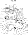
- the implant 10 may include a first piston 38 on the first arm 12, a second piston 40 on the second arm 14, and a central piston 42 at the hinge portion 16.
- the pistons may be individually controlled via separate hydraulic pressure channels formed within the implant, or, as in the embodiment of FIGS. 1-9 , they may be controlled by a common hydraulic pressure channel.
- a channel 44 formed within the first arm 12 may communicate with the cylinder 46 within which the first piston 38 is disposed. That way, hydraulic fluid within the channel 44 may cause outward expansion of the first piston 38.
- a seal member which may be in the form of an o-ring 47a, may be provided between the first piston 38 and the associated cylinder 46, so that those components can slide with respect to one another while preventing hydraulic fluid from escaping at that interface.
- the channel 44 may communicate with an opening so as to be supplied with pressurized hydraulic fluid from the delivery tool 18.
- the channel 44 may communicate with the bore 21, so that the hydraulic fluid may be supplied to the channel 44 by a conduit 48 in the delivery tool 18.
- the supply for the hydraulic fluid need not be provided through the same bore 21 used to anchor the implant 10 to the delivery tool 18, however, and alternative embodiments may, for example, include a separate opening in the outer surface of the implant for communication with a conduit 48 of the delivery tool 18.
- the channel 44 may also communicate with the cylinder 50 within which the central piston 42 is disposed, so that the hydraulic fluid may also cause outward expansion of the central piston 42.
- the communication between the channel 44 and the cylinder 50 may either be direct communication or communication via an intervening pathway, such as via angled channel 52 illustrated in FIG. 6 .
- Channel 52 may be formed by drilling an angled bore from outside the first arm 12 to the distal end of the cylinder 50, such that the bore intersects the channel 44. If formed in that manner, the extraneous end 54 of the channel 52 may subsequently be plugged, so that the hydraulic fluid does not escape the implant 10 via that path.
- a seal member, which may be in the form of an o-ring 47b, may be provided between the central piston 42 and the associated cylinder 50, so that those components can slide with respect to one another while preventing hydraulic fluid from escaping at that interface.
- the articulating connection between the first arm 12 and the second arm 14 at hinge portion 16 may be constructed so as to allow for the communication of the hydraulic fluid between the first arm 12 and the second arm 14.
- the second arm 14 includes a circular plate 56 at the distal end 36 of the implant 10. That circular plate includes a post 58 projecting perpendicular thereto.
- the first arm 12 has a cylindrical portion 60 corresponding to the shape of the circular plate 56 and having an opening 62 in the bottom surface thereof for receiving the post 58 therethrough, as shown in FIG. 7 .
- a bushing 64 may be secured (e.g., press fit) onto the post 58 after it has been received through the opening 62, so as to prevent the post 58 from withdrawing from the opening 62 while allowing for pivoting between those components.
- the post 58 may be hollow, so as to communicate with the interior of the cylinder 50. Additionally, to allow for pivoting about the post 58 while preventing hydraulic fluid from escaping at its interface with the opening 62, a seal member, which may be in the form of an o-ring 47-c, may be provided at that interface, such as by positioning the seal member around the post 58 between the bottom surface of the first arm 12 and the bushing 64.
- the hollow post 58 in the second arm 14 may communicate with a channel 66 in the second arm 14 that also communicates with the cylinder 68 within which the second piston 40 is disposed, so that the hydraulic fluid may also drive the outward expansion of the second piston 40.
- the channel 66 may be formed by drilling a bore along the second arm 14 from the proximal end 20 of the implant 10. If formed in that manner, the extraneous end 67 of the channel 66 may subsequently be plugged, so that the hydraulic fluid does not escape the implant 10 via that path.
- the implant 10 may include a locking system to lock the positions of the pistons, at least by preventing them from retracting back into the cylinders once expanded.
- the pistons may include ratcheting components that allow the pistons to move in the expansion direction, but automatically resist retraction of the pistons in the opposite direction. Such ratcheting components may also be selectively unlockable, in order to allow the pistons to retract when desired.
- ratcheting components is shown in the embodiment of the implant illustrated in FIGS. 1-9 and will now be discussed.
- Linear compression springs (not shown) are received around the control cables 82, 83 within each recess 78, 79, so as to bias the pawls 76, 77 along the recesses 78, 79 and into engagement with the ratcheting teeth 74.
- the respective pawls 76, 77 will slide along the respective recesses 78, 79 away from the vertical posts 70, 72, thus disengaging the pawls form the ratcheting teeth 74 and allowing the pistons 38, 40 to retract back into their respective cylinders.
- the central piston 42 can similarly be controlled by a corresponding pawl 88 received within a recess 89 in the outer surface of the implant 10 and held there by a retaining plate 90 affixed to the outer surface of the implant.
- the pawl 88 is biased by a spring (not shown) into engagement with ratcheting teeth 74 on the outer surface of the piston 42, and the pawl 88 can be disengaged from the ratcheting teeth 74 of the piston 42 by the same control cable 82 that controls pawl 76, which control cable 82 connects to the pawl 76 via connecting hole 91.
- the central piston 42 may also include a vertical post 93 received within a bore 94 in the implant 10 to help constrain the rotational orientation of the piston 42 and help guide the expansion of the piston 42 along a linear path.
- each piston 38, 40, 42 may be connected to a respective upper lock support 53a-c that is structured to releasably engage an associated lower lock support 51a-c.
- the upper lock supports 53a-c may each resemble an inverted spiral staircase integrally formed inside the respective piston 38, 40, 42, and the lower lock supports 51a-c may each resemble an upright spiral staircase rotatably positioned within the respective cylinder 46, 48, 50.
- the unlocking of any one of the lower lock supports 51a-c may thus include pushing the associated rack gear 33a-c to rotate the lower lock support out of engagement with the upper lock support, which further compresses the associated spring 31a-c.
- lower lock support 51a is engaged by rack gear 33a
- lower lock support 51c is engaged by rack gear 33c.
- Both of those rack gears 33a, 33c may include engagement plates 29 at their proximal ends, so that the associated lower lock supports 51a, 51c can be unlocked by pushing the engagement plates 29, and thus the rack gears, in the distal direction.
- the rack gears 33a, 33c may be positioned within the hydraulic channel 44 formed within the first arm 12, such that the engagement plates 29 are accessible via the bore 21, as shown in FIG. 11A .
- Diameter of central piston 42 Diameter of first and second pistons 38, 40 (mm) Area of central piston 42 (mm 2 ) Area of first and second pistons 38, 40 (mm 2 ) Force ratio (first and second pistons 38, 40 : central piston 42) 5 3 314.16 113.10 0.72 6 3 452.39 113.10 0.50 7 3 615.75 113.10 0.37 5 4 314.16 201.06 1.28 6 4 452.39 201.06 0.89 7 4 615.75 201.06 0.65 5 5 314.16 314.16 2.00 6 5 452.39 314.16 1.39 7 5 615.75 314.16 1.02 9 3 1017.88 113.10 0.22 9 4.5 1017.88 254.47 0.5 9 6 1017.88 452.39 0.89 7.6 3 725.83 113.10 0.31 7.6 4 725.83 201.06 0.55 7.6 5 725.
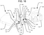
- one of the linkages 116a may be a straight link 116a connecting the left proximal corner of the second segment 114 to a distal end of the first segment 112, either centrally located in the left/right direction or towards the right side of the first segment 112.
- Another linkage 116b may connect the right proximal corner of the second segment 114 to a left side of the first segment 112, proximally of the distal end. That second linkage 116b may have a bent profile (e.g., with a 90° bend), so as to avoid interference with the first linkage 116a.
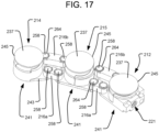
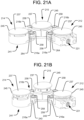
- straight linkages such as those illustrated in the embodiment of FIGS. 17-22 ), crossing linkages (not shown), or other suitable linkage arrangements may be used.
- Each segment 112, 114 of the implant 110 may comprise a top plate 145 having an upper vertebral engaging surface 137 and a bottom plate 143 having a lower vertebral engaging surface 41. Hydraulically driven pistons 138 received in corresponding cylinders 146, similar to those discussed above, can be positioned between the top and bottom plates 145, 143 for driving them apart.
- the segments 112, 114 may also include any appropriate locking system for automatically preventing the top and bottom plates 145, 143 from retracting back towards one another, except when deliberately unlocked by the user.
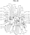
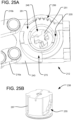
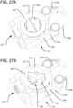
- each segment 112, 114 may have a respective locking element that may take the form of any of the locking elements discussed above or those disclosed in the '620 Patent or the ⁇ 513 Application. Alternatively, the locking elements may take the form of those discussed below in connection with FIGS. 23-29 .
- seal members which may be in the form of o-rings 147, may be positioned in corresponding grooves 149 of the posts 158, both above and below the slots 152, so as to seal the network of fluid channels defined within the linkages 116 while allowing the linkages to pivot.
- one or more pistons 238 may be independently controlled via a separate pressure channel.
- the different linkages 116, 216 may thus be on different pressure channel circuits that bypass certain pistons.
- the pressure channel communicating with the inner linkages 216a may bypass the piston 238 of the central segment 215, while communicating with the pistons 238 of the other segments 212, 214, and the pressure channel communicating with the outer linkages 216b may only serve the piston 238 of the central segment 215, while bypassing the pistons 238 of the other segments.
- Other embodiments may include any other combinations of pistons on different pressure channels.
- the embodiment of FIGS. 17-29 may include a different locking system to lock the positions of the pistons 238 than those discussed above. That is, as shown in FIGS. 23-29 , the locking system of each segment 212, 214, 215 of the implant 210 may include a lower lock support 251 coupled with the bottom plate 243, which lower lock support is movably engageable with an associated upper lock support 253 coupled to the expanding top plate 245. Like the upper lock supports 53a-c of the embodiment of FIGS. 10-11 , the upper lock supports 253 of the embodiment of FIGS. 17-29 are integrally formed inside the respective pistons 238 and resemble an inverted spiral staircase. The lower lock supports 251 may also resemble an upright spiral staircase positioned within the respective cylinders 246.
- the ratcheting ring 295 is received within an arcuate groove 205 at the top end of the cylinder 246, in order to constrain the position of the ratcheting ring about the longitudinal axis of the piston 238 while permitting the ratcheting ring to rotate about that axis, and the vertical position of the ratcheting ring 295 is constrained between the cam ring 259 and the top of the cylinder 246.
Landscapes
- Health & Medical Sciences (AREA)
- Engineering & Computer Science (AREA)
- Biomedical Technology (AREA)
- Orthopedic Medicine & Surgery (AREA)
- Neurology (AREA)
- Transplantation (AREA)
- Heart & Thoracic Surgery (AREA)
- Oral & Maxillofacial Surgery (AREA)
- Cardiology (AREA)
- Vascular Medicine (AREA)
- Life Sciences & Earth Sciences (AREA)
- Animal Behavior & Ethology (AREA)
- General Health & Medical Sciences (AREA)
- Public Health (AREA)
- Veterinary Medicine (AREA)
- Physical Education & Sports Medicine (AREA)
- Prostheses (AREA)
- Surgical Instruments (AREA)
Applications Claiming Priority (1)
| Application Number | Priority Date | Filing Date | Title |
|---|---|---|---|
| US201662413038P | 2016-10-26 | 2016-10-26 |
Publications (2)
| Publication Number | Publication Date |
|---|---|
| EP3315096A1 EP3315096A1 (en) | 2018-05-02 |
| EP3315096B1 true EP3315096B1 (en) | 2023-08-16 |
Family
ID=60186200
Family Applications (1)
| Application Number | Title | Priority Date | Filing Date |
|---|---|---|---|
| EP17198694.6A Active EP3315096B1 (en) | 2016-10-26 | 2017-10-26 | Expandable interbody implant with lateral articulation |
Country Status (4)
| Country | Link |
|---|---|
| US (3) | US10485675B2 (https=) |
| EP (1) | EP3315096B1 (https=) |
| JP (1) | JP7202067B2 (https=) |
| AU (1) | AU2017251734B2 (https=) |
Families Citing this family (26)
| Publication number | Priority date | Publication date | Assignee | Title |
|---|---|---|---|---|
| US9265620B2 (en) | 2011-03-18 | 2016-02-23 | Raed M. Ali, M.D., Inc. | Devices and methods for transpedicular stabilization of the spine |
| US8663332B1 (en) | 2012-12-13 | 2014-03-04 | Ouroboros Medical, Inc. | Bone graft distribution system |
| US10687962B2 (en) | 2013-03-14 | 2020-06-23 | Raed M. Ali, M.D., Inc. | Interbody fusion devices, systems and methods |
| KR20160010862A (ko) | 2013-03-14 | 2016-01-28 | 라에드 엠. 알리, 엠.디., 인크. | 측방 요추체간 유합술 장치, 시스템 및 그 방법 |
| US9186259B2 (en) | 2013-09-09 | 2015-11-17 | Ouroboros Medical, Inc. | Expandable trials |
| US9060876B1 (en) | 2015-01-20 | 2015-06-23 | Ouroboros Medical, Inc. | Stabilized intervertebral scaffolding systems |
| AU2017228529B2 (en) | 2016-09-12 | 2022-03-10 | Vb Spine Us Opco Llc | Interbody implant with independent control of expansion at multiple locations |
| US9883953B1 (en) | 2016-09-21 | 2018-02-06 | Integrity Implants Inc. | Stabilized laterovertically-expanding fusion cage systems with tensioner |
| AU2017251734B2 (en) | 2016-10-26 | 2022-10-20 | Vb Spine Us Opco Llc | Expandable interbody implant with lateral articulation |
| EP4623870A3 (en) | 2017-01-10 | 2025-12-24 | Integrity Implants Inc. | Expandable intervertebral fusion device |
| WO2019023251A1 (en) | 2017-07-24 | 2019-01-31 | Integrity Implants, Inc. | SURGICAL IMPLANT AND ASSOCIATED METHODS |
| EP3742990B1 (en) | 2018-03-01 | 2026-02-11 | Integrity Implants Inc. | Expandable fusion device with independent expansion systems |
| KR102379915B1 (ko) * | 2020-03-18 | 2022-03-29 | 주식회사 엔닥 | 최소 침습 수술용 케이지 |
| US11816831B2 (en) | 2020-04-29 | 2023-11-14 | Medtronic Navigation, Inc. | System and method for navigating and illustrating a procedure |
| US11890060B2 (en) | 2020-04-29 | 2024-02-06 | Medtronic Navigation, Inc. | System and method for navigating and illustrating a procedure |
| US12329652B2 (en) | 2020-07-20 | 2025-06-17 | Integrity Implants Inc. | Expandable fusion device with independent expansion systems |
| KR20220017092A (ko) * | 2020-08-04 | 2022-02-11 | 임병철 | 추간 케이지 |
| EP4358904A4 (en) * | 2021-06-22 | 2025-07-09 | Musc Found For Res Dev | ARTICULATED EXPANDABLE DEVICE |
| US12453640B2 (en) | 2021-07-16 | 2025-10-28 | Blue Ocean Spine Gmbh | Adjustable spinal implants, associated instruments and methods |
| US12318307B2 (en) | 2021-07-16 | 2025-06-03 | Blue Ocean Spine Gmbh | Adjustable spinal implants, associated instruments and methods |
| US12274627B2 (en) * | 2021-07-20 | 2025-04-15 | Globus Medical, Inc. | Interlaminar lumbar interbody fusion system and associated robotic systems |
| US11534309B1 (en) * | 2021-07-20 | 2022-12-27 | Globus Medical Inc. | Interlaminar lumbar interbody fusion implants, intradiscal implants, instruments, and methods |
| US11730606B2 (en) * | 2021-12-22 | 2023-08-22 | Ctl Biotec, Corporation | Expandable bi-dimensional interbody and method of manufacturing the same |
| KR102914108B1 (ko) * | 2022-03-15 | 2026-01-16 | 가톨릭관동대학교산학협력단 | 루프 변형 확장형 케이지 |
| US12085153B2 (en) * | 2022-10-11 | 2024-09-10 | Aegis Spine, Inc. | Adjustable spinal plate |
| US12533242B2 (en) | 2023-01-18 | 2026-01-27 | Blue Ocean Spine Gmbh | Adjustable spinal implants and related deployment instruments |
Family Cites Families (222)
| Publication number | Priority date | Publication date | Assignee | Title |
|---|---|---|---|---|
| US3875595A (en) | 1974-04-15 | 1975-04-08 | Edward C Froning | Intervertebral disc prosthesis and instruments for locating same |
| US7452359B1 (en) | 1988-06-13 | 2008-11-18 | Warsaw Orthopedic, Inc. | Apparatus for inserting spinal implants |
| US4969888A (en) | 1989-02-09 | 1990-11-13 | Arie Scholten | Surgical protocol for fixation of osteoporotic bone using inflatable device |
| US4932975A (en) | 1989-10-16 | 1990-06-12 | Vanderbilt University | Vertebral prosthesis |
| US5236460A (en) | 1990-02-12 | 1993-08-17 | Midas Rex Pneumatic Tools, Inc. | Vertebral body prosthesis |
| WO1998020939A2 (en) | 1996-11-15 | 1998-05-22 | Advanced Bio Surfaces, Inc. | Biomaterial system for in situ tissue repair |
| US5980522A (en) | 1994-07-22 | 1999-11-09 | Koros; Tibor | Expandable spinal implants |
| US5665122A (en) | 1995-01-31 | 1997-09-09 | Kambin; Parviz | Expandable intervertebral cage and surgical method |
| FR2730158B1 (fr) | 1995-02-06 | 1999-11-26 | Jbs Sa | Dispositif de maintien d'un ecartement normal entre les vertebres et destine au remplacement de vertebres manquantes |
| US5782919A (en) | 1995-03-27 | 1998-07-21 | Sdgi Holdings, Inc. | Interbody fusion device and method for restoration of normal spinal anatomy |
| DE19519101B4 (de) | 1995-05-24 | 2009-04-23 | Harms, Jürgen, Prof. Dr. | Höhenverstellbarer Wirbelkörperersatz |
| US5653763A (en) | 1996-03-29 | 1997-08-05 | Fastenetix, L.L.C. | Intervertebral space shape conforming cage device |
| US6835207B2 (en) | 1996-07-22 | 2004-12-28 | Fred Zacouto | Skeletal implant |
| FR2753368B1 (fr) | 1996-09-13 | 1999-01-08 | Chauvin Jean Luc | Cage d'osteosynthese expansive |
| US5827328A (en) | 1996-11-22 | 1998-10-27 | Buttermann; Glenn R. | Intervertebral prosthetic device |
| US6039761A (en) | 1997-02-12 | 2000-03-21 | Li Medical Technologies, Inc. | Intervertebral spacer and tool and method for emplacement thereof |
| ES2302349T3 (es) | 1997-03-07 | 2008-07-01 | Disc-O-Tech Medical Technologies, Ltd. | Sistemas para la estabilizacion, fijacion y reparacion osea y vertebral percutaneas. |
| US5916267A (en) | 1997-04-07 | 1999-06-29 | Arthit Sitiso | Anterior spinal implant system for vertebral body prosthesis |
| EP0975288B1 (de) | 1997-04-15 | 2002-10-02 | Synthes AG Chur | Teleskopierende wirbelprothese |
| FR2762778B1 (fr) | 1997-05-02 | 1999-07-16 | Stryker France Sa | Implant notamment pour le remplacement d'un corps vertebral en chirurgie du rachis |
| US5865848A (en) | 1997-09-12 | 1999-02-02 | Artifex, Ltd. | Dynamic intervertebral spacer and method of use |
| EP0904751B1 (de) | 1997-09-30 | 2003-08-20 | Centerpulse Orthopedics Ltd. | Rohrförmiger Stützkörper zum Überbrücken zweier Wirbel |
| DE19807236C2 (de) * | 1998-02-20 | 2000-06-21 | Biedermann Motech Gmbh | Zwischenwirbelimplantat |
| KR20010053129A (ko) | 1998-06-23 | 2001-06-25 | 딤소 디스트리뷰숑 메디칼 두 수드 웨스트 | 고정 엘리먼트를 구비한 체벽 사이의 척추 임플란트 |
| MY130565A (en) | 1998-09-18 | 2007-06-29 | Samsung Electronics Co Ltd | Near-field optical storage medium and optical data storage system therefor |
| US6193757B1 (en) | 1998-10-29 | 2001-02-27 | Sdgi Holdings, Inc. | Expandable intervertebral spacers |
| US6214012B1 (en) | 1998-11-13 | 2001-04-10 | Harrington Arthritis Research Center | Method and apparatus for delivering material to a desired location |
| FR2787018B1 (fr) | 1998-12-11 | 2001-03-02 | Dimso Sa | Prothese de disque intervertebral a enceinte de liquide |
| US6102950A (en) | 1999-01-19 | 2000-08-15 | Vaccaro; Alex | Intervertebral body fusion device |
| US6454806B1 (en) | 1999-07-26 | 2002-09-24 | Advanced Prosthetic Technologies, Inc. | Spinal surgical prosthesis |
| WO2002009626A1 (en) | 1999-07-26 | 2002-02-07 | Advanced Prosthetic Technologies, Inc. | Improved spinal surgical prosthesis |
| US7824445B2 (en) | 1999-07-26 | 2010-11-02 | Ladislau Biro | Corpectomy vertebral body replacement implant system |
| US7177690B2 (en) | 1999-07-27 | 2007-02-13 | Advanced Bionics Corporation | Implantable system having rechargeable battery indicator |
| WO2009033100A1 (en) | 2007-09-07 | 2009-03-12 | Intrinsic Therapeutics, Inc. | Bone anchoring systems |
| WO2001013807A2 (en) | 1999-08-26 | 2001-03-01 | Sdgi Holdings, Inc. | Devices and methods for implanting fusion cages |
| US6866682B1 (en) | 1999-09-02 | 2005-03-15 | Stryker Spine | Distractable corpectomy device |
| US6875235B2 (en) | 1999-10-08 | 2005-04-05 | Bret A. Ferree | Prosthetic joints with contained compressible resilient members |
| US7060100B2 (en) | 1999-10-08 | 2006-06-13 | Ferree Bret A | Artificial disc and joint replacements with modular cushioning components |
| FR2799638B1 (fr) | 1999-10-14 | 2002-08-16 | Fred Zacouto | Fixateur et articulation vertebrale |
| US6764491B2 (en) | 1999-10-21 | 2004-07-20 | Sdgi Holdings, Inc. | Devices and techniques for a posterior lateral disc space approach |
| US6830570B1 (en) | 1999-10-21 | 2004-12-14 | Sdgi Holdings, Inc. | Devices and techniques for a posterior lateral disc space approach |
| WO2001028469A2 (en) | 1999-10-21 | 2001-04-26 | Sdgi Holdings, Inc. | Devices and techniques for a posterior lateral disc space approach |
| AU778410B2 (en) | 1999-12-01 | 2004-12-02 | Henry Graf | Intervertebral stabilising device |
| FR2803188A1 (fr) * | 1999-12-29 | 2001-07-06 | Henry Graf | Dispositif et ensemble intervertebraux de stabilisation |
| US6296665B1 (en) | 2000-03-20 | 2001-10-02 | Electro-Biology, Inc. | Method and apparatus for spinal fixation |
| AR027685A1 (es) | 2000-03-22 | 2003-04-09 | Synthes Ag | Forma de tejido y metodo para realizarlo |
| US6585699B2 (en) | 2000-04-13 | 2003-07-01 | Nna/S | Drug delivery device provided with a one-way mechanism |
| US6821298B1 (en) | 2000-04-18 | 2004-11-23 | Roger P. Jackson | Anterior expandable spinal fusion cage system |
| US7018416B2 (en) | 2000-07-06 | 2006-03-28 | Zimmer Spine, Inc. | Bone implants and methods |
| US20020026244A1 (en) | 2000-08-30 | 2002-02-28 | Trieu Hai H. | Intervertebral disc nucleus implants and methods |
| US6582467B1 (en) | 2000-10-31 | 2003-06-24 | Vertelink Corporation | Expandable fusion cage |
| US7097645B2 (en) | 2001-06-04 | 2006-08-29 | Sdgi Holdings, Inc. | Dynamic single-lock anterior cervical plate system having non-detachably fastened and moveable segments |
| NL1018438C1 (nl) | 2001-07-02 | 2003-01-08 | Baat Medical Engineering B V | In- en uitklapbaar gereedschap voor plaatsing in een ruggenwervel. |
| US6375682B1 (en) | 2001-08-06 | 2002-04-23 | Lewis W. Fleischmann | Collapsible, rotatable and expandable spinal hydraulic prosthetic device |
| TW545211U (en) | 2001-08-29 | 2003-08-01 | Jung-Chiuan Ye | Device for fastening spine |
| US6648917B2 (en) | 2001-10-17 | 2003-11-18 | Medicinelodge, Inc. | Adjustable bone fusion implant and method |
| US6960232B2 (en) | 2002-04-25 | 2005-11-01 | Blackstone Medical, Inc. | Artificial intervertebral disc |
| CA2485015A1 (en) | 2002-05-06 | 2003-11-13 | Sdgi Holdings, Inc. | Instrumentation and methods for preparation of an intervertebral space |
| US7060037B2 (en) | 2002-05-08 | 2006-06-13 | Medport, Llc | Digital thermometer for measuring body temperature |
| US7066958B2 (en) | 2002-05-10 | 2006-06-27 | Ferree Bret A | Prosthetic components with partially contained compressible resilient members |
| US8388684B2 (en) | 2002-05-23 | 2013-03-05 | Pioneer Signal Technology, Inc. | Artificial disc device |
| DE60322066D1 (de) | 2002-08-15 | 2008-08-21 | Hfsc Co | Bandscheibenimplantat |
| BR0313499A (pt) | 2002-08-15 | 2005-07-05 | David Gerber | Disco intervertebral |
| WO2004016250A1 (en) | 2002-08-19 | 2004-02-26 | Orchid Health Care | Sustained release pharmaceutical composition of a cephalosporin antibiotic |
| US7018415B1 (en) | 2002-09-23 | 2006-03-28 | Sdgi Holdings, Inc. | Expandable spinal fusion device and methods of promoting spinal fusion |
| US7214243B2 (en) | 2002-10-21 | 2007-05-08 | 3Hbfm, Llc | Intervertebral disk prosthesis |
| AR037168A1 (es) | 2002-10-30 | 2004-10-27 | Carrasco Mauricio Rodolfo | Implante para reemplazo vertebral y reestablecimiento de la normal curvatura espinal. |
| US6723126B1 (en) | 2002-11-01 | 2004-04-20 | Sdgi Holdings, Inc. | Laterally expandable cage |
| DE10253170A1 (de) | 2002-11-14 | 2004-06-03 | Sepitec Foundation | Druckfester Hohlkörper zum Einsatz bei Versteifungsoperationen an der Wirbelsäule |
| US7485143B2 (en) | 2002-11-15 | 2009-02-03 | Abbott Cardiovascular Systems Inc. | Apparatuses and methods for heart valve repair |
| US7660623B2 (en) | 2003-01-30 | 2010-02-09 | Medtronic Navigation, Inc. | Six degree of freedom alignment display for medical procedures |
| US7828849B2 (en) * | 2003-02-03 | 2010-11-09 | Warsaw Orthopedic, Inc. | Expanding interbody implant and articulating inserter and method |
| FR2850563B1 (fr) | 2003-02-05 | 2005-11-04 | Scient X | Implant de remplacement vertebral et appareil de distraction pour la mise en place de l'implant |
| US7094257B2 (en) | 2003-02-14 | 2006-08-22 | Zimmer Spine, Inc. | Expandable intervertebral implant cage |
| WO2004080356A2 (en) | 2003-03-07 | 2004-09-23 | Smart Disc, Inc. | Spinal implant with securement spikes |
| US7824444B2 (en) | 2003-03-20 | 2010-11-02 | Spineco, Inc. | Expandable spherical spinal implant |
| EP1610740A4 (en) | 2003-04-04 | 2009-04-08 | Theken Disc Llc | ARTIFICIAL DISC PROSTHESIS |
| EP1622549B1 (de) | 2003-04-11 | 2007-12-12 | Synthes GmbH | Verankerungsmittel für zwischenwirbelimplantate |
| US7419505B2 (en) | 2003-04-22 | 2008-09-02 | Fleischmann Lewis W | Collapsible, rotatable, and tiltable hydraulic spinal disc prosthesis system with selectable modular components |
| US6981989B1 (en) | 2003-04-22 | 2006-01-03 | X-Pantu-Flex Drd Limited Liability Company | Rotatable and reversibly expandable spinal hydraulic prosthetic device |
| US20090005874A1 (en) | 2003-04-22 | 2009-01-01 | Fleischmann Lewis W | Compressible, rotatable, and tiltable hydraulic spinal disc prosthesis system with selectable modular components |
| US7407513B2 (en) | 2003-05-02 | 2008-08-05 | Smart Disc, Inc. | Artificial spinal disk |
| US7621956B2 (en) | 2003-07-31 | 2009-11-24 | Globus Medical, Inc. | Prosthetic spinal disc replacement |
| US7153325B2 (en) | 2003-08-01 | 2006-12-26 | Ultra-Kinetics, Inc. | Prosthetic intervertebral disc and methods for using the same |
| US7204853B2 (en) | 2003-08-05 | 2007-04-17 | Flexuspine, Inc. | Artificial functional spinal unit assemblies |
| US7753958B2 (en) | 2003-08-05 | 2010-07-13 | Gordon Charles R | Expandable intervertebral implant |
| US7316714B2 (en) | 2003-08-05 | 2008-01-08 | Flexuspine, Inc. | Artificial functional spinal unit assemblies |
| EP1651150B1 (en) | 2003-08-07 | 2021-03-24 | Dynamic Spine, Inc. | Intervertebral prosthetic device and associated devices and methods for implanting the intervertebral prosthetic device |
| WO2005034864A2 (en) | 2003-10-08 | 2005-04-21 | University Of North Carolina At Chapel Hill | Spine replacement system |
| US7819922B2 (en) | 2003-10-16 | 2010-10-26 | Spinal Generations, Llc | Vertebral prosthesis |
| US7217293B2 (en) | 2003-11-21 | 2007-05-15 | Warsaw Orthopedic, Inc. | Expandable spinal implant |
| CA2552806C (en) | 2004-01-09 | 2013-04-02 | Kent D. Yundt | Method, system and apparatus for interbody fusion |
| US7485145B2 (en) | 2004-02-23 | 2009-02-03 | Alphatec Spine, Incorporated | Artificial intervertebral disc assembly |
| US20050229433A1 (en) | 2004-03-03 | 2005-10-20 | Cachia Victor V | Catheter deliverable foot implant and method of delivering the same |
| US7507241B2 (en) | 2004-04-05 | 2009-03-24 | Expanding Orthopedics Inc. | Expandable bone device |
| US7854766B2 (en) | 2004-05-13 | 2010-12-21 | Moskowitz Nathan C | Artificial total lumbar disc for unilateral safe and simple posterior placement in the lumbar spine, and removable bifunctional screw which drives vertical sliding expansile plate expansion, and interplate widening, and angled traction spikes |
| US7794499B2 (en) | 2004-06-08 | 2010-09-14 | Theken Disc, L.L.C. | Prosthetic intervertebral spinal disc with integral microprocessor |
| US7470273B2 (en) | 2004-06-25 | 2008-12-30 | Ebi, Llc | Tool for intervertebral implant manipulation |
| US7351261B2 (en) | 2004-06-30 | 2008-04-01 | Depuy Spine, Inc. | Multi-joint implant |
| US20060036259A1 (en) | 2004-08-03 | 2006-02-16 | Carl Allen L | Spine treatment devices and methods |
| US7883543B2 (en) | 2004-10-01 | 2011-02-08 | Spinal Generations, Llc | Vertebral prosthesis and spinal fixation system |
| US20060085073A1 (en) | 2004-10-18 | 2006-04-20 | Kamshad Raiszadeh | Medical device systems for the spine |
| US8025680B2 (en) | 2004-10-20 | 2011-09-27 | Exactech, Inc. | Systems and methods for posterior dynamic stabilization of the spine |
| US20060089719A1 (en) | 2004-10-21 | 2006-04-27 | Trieu Hai H | In situ formation of intervertebral disc implants |
| US7594888B2 (en) | 2004-10-29 | 2009-09-29 | Depuy Spine, Inc. | Expandable ports and methods for minimally invasive surgery |
| US7291158B2 (en) | 2004-11-12 | 2007-11-06 | Boston Scientific Scimed, Inc. | Cutting balloon catheter having a segmented blade |
| US20060142861A1 (en) | 2004-12-29 | 2006-06-29 | Murray Ian P | Spinal disc replacement |
| US20060167547A1 (en) | 2005-01-21 | 2006-07-27 | Loubert Suddaby | Expandable intervertebral fusion implants having hinged sidewalls |
| US9034041B2 (en) | 2005-03-31 | 2015-05-19 | Life Spine, Inc. | Expandable spinal interbody and intravertebral body devices |
| US7575580B2 (en) | 2005-04-15 | 2009-08-18 | Warsaw Orthopedic, Inc. | Instruments, implants and methods for positioning implants into a spinal disc space |
| US7722674B1 (en) | 2005-08-12 | 2010-05-25 | Innvotec Surgical Inc. | Linearly expanding spine cage for enhanced spinal fusion |
| US20070050030A1 (en) | 2005-08-23 | 2007-03-01 | Kim Richard C | Expandable implant device with interchangeable spacer |
| US7731753B2 (en) | 2005-09-01 | 2010-06-08 | Spinal Kinetics, Inc. | Prosthetic intervertebral discs |
| US8070813B2 (en) | 2005-09-26 | 2011-12-06 | Coalign Innovations, Inc. | Selectively expanding spine cage, hydraulically controllable in three dimensions for vertebral body replacement |
| US7985256B2 (en) * | 2005-09-26 | 2011-07-26 | Coalign Innovations, Inc. | Selectively expanding spine cage, hydraulically controllable in three dimensions for enhanced spinal fusion |
| US9028550B2 (en) * | 2005-09-26 | 2015-05-12 | Coalign Innovations, Inc. | Selectively expanding spine cage with enhanced bone graft infusion |
| US8236058B2 (en) | 2005-09-27 | 2012-08-07 | Fabian Henry F | Spine surgery method and implant |
| US20070123987A1 (en) | 2005-11-02 | 2007-05-31 | Bernstein Avi J | Curvilinear cervical interbody device |
| WO2007075878A2 (en) | 2005-12-22 | 2007-07-05 | Endius, Inc. | Methods and devices for replacement of intervertebral discs |
| WO2007121320A2 (en) * | 2006-04-12 | 2007-10-25 | Spinalmotion, Inc. | Posterior spinal device and method |
| US20070270952A1 (en) | 2006-04-19 | 2007-11-22 | Spinal Kinetics, Inc. | Prosthetic intervertebral discs implantable by minimally invasive surgical techniques |
| US7854765B2 (en) * | 2006-04-20 | 2010-12-21 | Moskowitz Mosheh T | Electronically controlled artificial intervertebral disc with motor assisted actuation systems |
| US20070270961A1 (en) | 2006-04-25 | 2007-11-22 | Sdgi Holdings, Inc. | Spinal implant with deployable and retractable barbs |
| US7914581B2 (en) | 2006-04-27 | 2011-03-29 | Warsaw Orthopedic, Inc. | Expandable implant, instrument, and method |
| US8187331B2 (en) | 2006-04-27 | 2012-05-29 | Warsaw Orthopedic, Inc. | Expandable vertebral implant and methods of use |
| US7794501B2 (en) * | 2006-04-27 | 2010-09-14 | Wasaw Orthopedic, Inc. | Expandable intervertebral spacers and methods of use |
| US7708779B2 (en) * | 2006-05-01 | 2010-05-04 | Warsaw Orthopedic, Inc. | Expandable intervertebral spacers and methods of use |
| US20070288092A1 (en) | 2006-06-01 | 2007-12-13 | Bambakidis Nicholas | Expandable intervertebral implant and method |
| US7862618B2 (en) | 2006-07-19 | 2011-01-04 | Warsaw Orthopedic, Inc. | Expandable vertebral body implants and methods of use |
| US20080058931A1 (en) | 2006-07-21 | 2008-03-06 | John White | Expandable vertebral implant and methods of use |
| US7731752B2 (en) | 2006-07-21 | 2010-06-08 | Warsaw Orthopedic, Inc. | Implant with nested members and methods of use |
| US20080021556A1 (en) | 2006-07-21 | 2008-01-24 | Edie Jason A | Expandable vertebral implant and methods of use |
| WO2008021972A2 (en) * | 2006-08-10 | 2008-02-21 | Pioneer Surgical Technology, Inc. | Intervertebral disc space sizing tools and methods |
| US20080065082A1 (en) | 2006-09-08 | 2008-03-13 | Narissa Chang | Steerable rasp/trial inserter |
| US20080077150A1 (en) | 2006-09-22 | 2008-03-27 | Linh Nguyen | Steerable rasp/trial member inserter and method of use |
| JP4917485B2 (ja) | 2006-10-10 | 2012-04-18 | 株式会社堀場製作所 | 応力成分測定方法 |
| US20080177387A1 (en) | 2006-11-01 | 2008-07-24 | Warsaw Orthopedic, Inc. | Implants and Related Devices for Monitoring Bony Fusion |
| US8328871B2 (en) | 2006-11-09 | 2012-12-11 | Warsaw Orthopedic, Inc. | Expanding vertebral body implant |
| EP1925272B1 (en) * | 2006-11-23 | 2010-01-13 | BIEDERMANN MOTECH GmbH | Expandable intervertebral implant |
| GB0623801D0 (en) | 2006-11-29 | 2007-01-10 | Surgicraft Ltd | Orthopaedic implants and prosthesis |
| AU2007327053A1 (en) | 2006-11-29 | 2008-06-05 | Surgicraft Limited | Orthopaedic implants and prostheses |
| WO2008070863A2 (en) | 2006-12-07 | 2008-06-12 | Interventional Spine, Inc. | Intervertebral implant |
| US20100087924A1 (en) | 2007-01-05 | 2010-04-08 | University Of Virginia Patent Foundation | Expandable Intervertebral Prosthesis Device for Posterior Implantation and Related Method Thereof |
| WO2008112607A2 (en) | 2007-03-09 | 2008-09-18 | Blue Fury Consulting, Llc | Spinal implant |
| AU2008224951A1 (en) | 2007-03-13 | 2008-09-18 | Synthes Gmbh | Adjustable intervertebral implant |
| US20090012612A1 (en) * | 2007-04-10 | 2009-01-08 | David White | Devices and methods for push-delivery of implants |
| US8273124B2 (en) * | 2007-05-17 | 2012-09-25 | Depuy Spine, Inc. | Self-distracting cage |
| EP1994900A1 (fr) | 2007-05-22 | 2008-11-26 | Flexismed SA | Implant vertébral inter-épineux |
| US7967867B2 (en) | 2007-05-31 | 2011-06-28 | Spine Wave, Inc. | Expandable interbody fusion device |
| WO2008148210A1 (en) | 2007-06-06 | 2008-12-11 | The Royal Institution For The Advancement Of Learning/Mcgill University | Prostethic vertebral body |
| US20090030399A1 (en) * | 2007-07-23 | 2009-01-29 | Kamshad Raiszadeh | Drug Delivery Device and Method |
| US8398649B2 (en) | 2007-08-06 | 2013-03-19 | Us Spine, Inc. | Articulating transforaminal lumbar interbody fusion inserter device and associated method of use |
| WO2009064787A2 (en) | 2007-11-12 | 2009-05-22 | Synthes (U.S.A.) | Adjustable height intervertebral implant |
| US8663331B2 (en) * | 2007-11-30 | 2014-03-04 | Custom Spine, Inc. | Maximum support TLIF implant |
| US7985231B2 (en) | 2007-12-31 | 2011-07-26 | Kyphon Sarl | Bone fusion device and methods |
| US8353961B2 (en) | 2008-02-07 | 2013-01-15 | K2M, Inc. | Expandable vertebral device with cam lock |
| US8932355B2 (en) | 2008-02-22 | 2015-01-13 | Coalign Innovations, Inc. | Spinal implant with expandable fixation |
| US8696751B2 (en) * | 2008-12-10 | 2014-04-15 | Coalign Innovations, Inc. | Adjustable distraction cage with linked locking mechanisms |
| US20100145455A1 (en) | 2008-12-10 | 2010-06-10 | Innvotec Surgical, Inc. | Lockable spinal implant |
| US8992620B2 (en) * | 2008-12-10 | 2015-03-31 | Coalign Innovations, Inc. | Adjustable distraction cage with linked locking mechanisms |
| US8267939B2 (en) | 2008-02-28 | 2012-09-18 | Stryker Spine | Tool for implanting expandable intervertebral implant |
| BRPI0909657A2 (pt) | 2008-03-07 | 2015-09-22 | Synthes Gmbh | dispositivo espaçador intersomático expansível |
| US20090248092A1 (en) * | 2008-03-26 | 2009-10-01 | Jonathan Bellas | Posterior Intervertebral Disc Inserter and Expansion Techniques |
| US8062368B2 (en) | 2008-04-24 | 2011-11-22 | Warsaw Orthopedic, Inc. | Expandable vertebral implants and methods of use |
| US8172902B2 (en) | 2008-07-17 | 2012-05-08 | Spinemedica, Llc | Spinal interbody spacers |
| WO2010009153A1 (en) * | 2008-07-18 | 2010-01-21 | Spinalmotion, Inc. | Posterior prosthetic intervertebral disc |
| JP2012513243A (ja) | 2008-12-22 | 2012-06-14 | ジンテス ゲゼルシャフト ミット ベシュレンクテル ハフツング | 拡張可能椎体置換デバイス及び方法 |
| US8535377B2 (en) | 2009-03-31 | 2013-09-17 | Imds Corporation | Double bundle ACL repair system |
| CN102481187B (zh) | 2009-03-31 | 2016-06-08 | 医学嵌入公司暨Imds共同创新公司 | 双束前十字韧带修复 |
| US8153785B2 (en) | 2009-04-06 | 2012-04-10 | Cheminpharma LLC | Stabilizing ligands for regulation of protein function |
| EP2419033B1 (en) | 2009-04-16 | 2015-12-16 | Howmedica Osteonics Corp. | Insertion handle for surgical implants |
| IN2012DN00952A (https=) | 2009-07-22 | 2015-04-10 | Spinex Tec Llc | |
| US9155628B2 (en) * | 2009-10-15 | 2015-10-13 | Globus Medical, Inc. | Expandable fusion device and method of installation thereof |
| US8353963B2 (en) * | 2010-01-12 | 2013-01-15 | Globus Medical | Expandable spacer and method for use thereof |
| DE102010047901B4 (de) | 2010-10-11 | 2019-01-10 | Heinrich Böhm | Implantat für die Wirbelsäule und Betätigungsinstrument |
| WO2012112592A2 (en) * | 2011-02-14 | 2012-08-23 | Medicinelodge, Inc Dba Imds Co-Innovation | Expandable intervertebral spacer |
| US8685095B2 (en) * | 2011-04-19 | 2014-04-01 | Warsaw Orthopedic, Inc. | Expandable implant system and methods of use |
| WO2013006669A2 (en) * | 2011-07-05 | 2013-01-10 | Expanding Orthopedics Inc. | Bone structural device |
| US8968402B2 (en) | 2011-10-18 | 2015-03-03 | Arthrocare Corporation | ACL implants, instruments, and methods |
| US9271777B2 (en) * | 2011-12-14 | 2016-03-01 | Biomet Spine, Llc | Unilateral moveable interbody fusion device and method of use |
| US8663329B2 (en) * | 2012-01-28 | 2014-03-04 | Mark J Ernst | Expandable implant for mammalian bony segment stabilization |
| US9060870B2 (en) | 2012-02-05 | 2015-06-23 | Michael J. Milella, Jr. | In-situ formed spinal implant |
| US9090029B2 (en) | 2012-02-06 | 2015-07-28 | Warsaw Orthopedic, Inc. | Pultrusion process for preparing composites having low percentage of fibers and articles made from same |
| US9233007B2 (en) | 2012-02-13 | 2016-01-12 | Blue Tip Biologics, Llc | Expandable self-anchoring interbody cage for orthopedic applications |
| US9532883B2 (en) * | 2012-04-13 | 2017-01-03 | Neuropro Technologies, Inc. | Bone fusion device |
| US10159583B2 (en) * | 2012-04-13 | 2018-12-25 | Neuropro Technologies, Inc. | Bone fusion device |
| US10117755B2 (en) * | 2012-04-16 | 2018-11-06 | Biospine, Llc | Multiple spindle adjustable interbody fusion devices and methods of use |
| US9144503B2 (en) | 2012-10-12 | 2015-09-29 | Warsaw Orthopedic, Inc. | Expandable spinal implant system and method |
| US9974664B2 (en) * | 2013-01-24 | 2018-05-22 | Biospine, Llc | Adjustable interbody fusion device and method of use |
| US9782265B2 (en) * | 2013-02-15 | 2017-10-10 | Globus Medical, Inc | Articulating and expandable vertebral implant |
| US10137004B2 (en) | 2013-02-27 | 2018-11-27 | Vivonics, Inc. | Insertion tools and methods for minimally invasive spinal fusion cage |
| US10004607B2 (en) * | 2013-03-01 | 2018-06-26 | Globus Medical, Inc. | Articulating expandable intervertebral implant |
| DE102013102451A1 (de) * | 2013-03-12 | 2014-09-18 | Heinrich Böhm | Aufspreizbares Implantat für die Wirbelsäule |
| US10154911B2 (en) * | 2013-03-13 | 2018-12-18 | Life Spine, Inc. | Expandable implant assembly |
| US9463099B2 (en) * | 2013-03-15 | 2016-10-11 | Expanding Orthopedics Inc. | Orthopedic expandable devices |
| JP6430708B2 (ja) * | 2013-03-15 | 2018-11-28 | ハウメディカ オステオニクス コーポレイションHowmedica Osteonics Corp. | リンクされたロッキング機構を備える調整可能な伸延ケージ |
| EP2996592B1 (en) * | 2013-05-13 | 2021-07-07 | BioSpine, LLC | Adjustable interbody fusion devices |
| DE102013107723A1 (de) * | 2013-07-19 | 2015-01-22 | Heinrich Böhm | Aufspreizbares Implantat für die Wirbelsäule |
| US9839528B2 (en) * | 2014-02-07 | 2017-12-12 | Globus Medical, Inc. | Variable lordosis spacer and related methods of use |
| WO2015136484A1 (en) * | 2014-03-12 | 2015-09-17 | Nlt Spine Ltd | Adjustable arcuate implant |
| US10034767B2 (en) * | 2014-06-03 | 2018-07-31 | Atlas Spine, Inc. | Spinal implant device |
| WO2016069796A1 (en) * | 2014-10-28 | 2016-05-06 | Spectrum Spine Ip Holdings, Llc | Expandable, adjustable inter-body fusion devices and methods |
| US20170312092A1 (en) * | 2014-10-31 | 2017-11-02 | Facet-Link Inc. | Fully expandable intervertebral fusion implant with traveller |
| EP3212130A1 (en) * | 2014-10-31 | 2017-09-06 | FACET-LINK Inc. | Fully expandable intervertebral fusion implant |
| US9592132B2 (en) * | 2015-01-09 | 2017-03-14 | Shape Memory Orthopedics | Shape-memory spinal fusion system |
| AU2015387084B2 (en) * | 2015-03-18 | 2020-02-13 | 41Medical Ag | Expandable spinal implant |
| US20170100255A1 (en) * | 2015-04-16 | 2017-04-13 | Expanding Orthopedics Inc. | Intervertebral cage for lateral approach |
| WO2016183382A1 (en) | 2015-05-12 | 2016-11-17 | Nuvasive, Inc. | Expandable lordosis intervertebral implants |
| US9833338B2 (en) * | 2015-06-30 | 2017-12-05 | Expanding Orthopedics Inc. | Tool for intervertebral cage |
| US9913727B2 (en) * | 2015-07-02 | 2018-03-13 | Medos International Sarl | Expandable implant |
| US10973650B2 (en) | 2015-12-30 | 2021-04-13 | Nuvasive, Inc. | Lordotic expandable fusion implant |
| US10548738B2 (en) * | 2016-04-07 | 2020-02-04 | Howmedica Osteonics Corp. | Expandable interbody implant |
| EP3228283B1 (en) | 2016-04-07 | 2023-10-25 | Howmedica Osteonics Corp. | Surgical insertion instruments |
| AU2017203369B2 (en) * | 2016-05-20 | 2022-04-28 | Vb Spine Us Opco Llc | Expandable interbody implant with lordosis correction |
| US9974662B2 (en) * | 2016-06-29 | 2018-05-22 | Globus Medical, Inc. | Expandable fusion device and method of installation thereof |
| US10052215B2 (en) * | 2016-06-29 | 2018-08-21 | Globus Medical, Inc. | Expandable fusion device and method of installation thereof |
| AU2017228529B2 (en) * | 2016-09-12 | 2022-03-10 | Vb Spine Us Opco Llc | Interbody implant with independent control of expansion at multiple locations |
| AU2017251734B2 (en) * | 2016-10-26 | 2022-10-20 | Vb Spine Us Opco Llc | Expandable interbody implant with lateral articulation |
| FR3058042B1 (fr) * | 2016-10-27 | 2021-12-10 | Ldr Medical | Implant intervertebral expansible |
| US10537436B2 (en) * | 2016-11-01 | 2020-01-21 | DePuy Synthes Products, Inc. | Curved expandable cage |
| US20180235769A1 (en) * | 2017-02-23 | 2018-08-23 | Expanding Orthopedics Inc., | Non-expandable multiple-segment lockable cage |
| US10111755B2 (en) * | 2017-02-24 | 2018-10-30 | Warsaw, Orthopedic, Inc. | Expanding interbody implant and articulating inserter and methods of use |
-
2017
- 2017-10-24 AU AU2017251734A patent/AU2017251734B2/en active Active
- 2017-10-26 JP JP2017207035A patent/JP7202067B2/ja active Active
- 2017-10-26 EP EP17198694.6A patent/EP3315096B1/en active Active
- 2017-10-26 US US15/794,693 patent/US10485675B2/en active Active
-
2019
- 2019-10-24 US US16/662,187 patent/US11071633B2/en active Active
-
2021
- 2021-06-25 US US17/358,735 patent/US11992418B2/en active Active
Also Published As
| Publication number | Publication date |
|---|---|
| AU2017251734A1 (en) | 2018-05-10 |
| EP3315096A1 (en) | 2018-05-02 |
| US11992418B2 (en) | 2024-05-28 |
| US11071633B2 (en) | 2021-07-27 |
| US10485675B2 (en) | 2019-11-26 |
| JP7202067B2 (ja) | 2023-01-11 |
| US20210315712A1 (en) | 2021-10-14 |
| JP2018122079A (ja) | 2018-08-09 |
| AU2017251734B2 (en) | 2022-10-20 |
| US20180110628A1 (en) | 2018-04-26 |
| US20200121471A1 (en) | 2020-04-23 |
Similar Documents
| Publication | Publication Date | Title |
|---|---|---|
| US11992418B2 (en) | Expandable interbody implant with lateral articulation | |
| US11058547B2 (en) | Interbody implant with independent control of expansion at multiple locations | |
| US20210251776A1 (en) | Intervertebral implant device with lordotic expansion | |
| US12390339B2 (en) | Expandable interbody spacer | |
| US8894710B2 (en) | Lockable spinal implant | |
| US20220313451A1 (en) | Intervertbral devices and related methods | |
| EP3245982B1 (en) | Expandable interbody implant with lordosis correction | |
| US9545316B2 (en) | Adjustable distraction cage with linked locking mechanisms | |
| US20130190878A1 (en) | Method for stabilizing spine | |
| US20220175547A1 (en) | Dual-action expandable intervertebral implants | |
| CN118873302B (zh) | 可多向撑开融合器和椎间植入系统 |
Legal Events
| Date | Code | Title | Description |
|---|---|---|---|
| PUAI | Public reference made under article 153(3) epc to a published international application that has entered the european phase |
Free format text: ORIGINAL CODE: 0009012 |
|
| STAA | Information on the status of an ep patent application or granted ep patent |
Free format text: STATUS: THE APPLICATION HAS BEEN PUBLISHED |
|
| AK | Designated contracting states |
Kind code of ref document: A1 Designated state(s): AL AT BE BG CH CY CZ DE DK EE ES FI FR GB GR HR HU IE IS IT LI LT LU LV MC MK MT NL NO PL PT RO RS SE SI SK SM TR |
|
| AX | Request for extension of the european patent |
Extension state: BA ME |
|
| STAA | Information on the status of an ep patent application or granted ep patent |
Free format text: STATUS: REQUEST FOR EXAMINATION WAS MADE |
|
| 17P | Request for examination filed |
Effective date: 20181026 |
|
| GRAP | Despatch of communication of intention to grant a patent |
Free format text: ORIGINAL CODE: EPIDOSNIGR1 |
|
| STAA | Information on the status of an ep patent application or granted ep patent |
Free format text: STATUS: GRANT OF PATENT IS INTENDED |
|
| INTG | Intention to grant announced |
Effective date: 20230314 |
|
| P01 | Opt-out of the competence of the unified patent court (upc) registered |
Effective date: 20230427 |
|
| GRAS | Grant fee paid |
Free format text: ORIGINAL CODE: EPIDOSNIGR3 |
|
| GRAA | (expected) grant |
Free format text: ORIGINAL CODE: 0009210 |
|
| STAA | Information on the status of an ep patent application or granted ep patent |
Free format text: STATUS: THE PATENT HAS BEEN GRANTED |
|
| AK | Designated contracting states |
Kind code of ref document: B1 Designated state(s): AL AT BE BG CH CY CZ DE DK EE ES FI FR GB GR HR HU IE IS IT LI LT LU LV MC MK MT NL NO PL PT RO RS SE SI SK SM TR |
|
| REG | Reference to a national code |
Ref country code: GB Ref legal event code: FG4D |
|
| REG | Reference to a national code |
Ref country code: CH Ref legal event code: EP |
|
| REG | Reference to a national code |
Ref country code: DE Ref legal event code: R096 Ref document number: 602017072726 Country of ref document: DE |
|
| REG | Reference to a national code |
Ref country code: IE Ref legal event code: FG4D |
|
| REG | Reference to a national code |
Ref country code: LT Ref legal event code: MG9D |
|
| REG | Reference to a national code |
Ref country code: NL Ref legal event code: MP Effective date: 20230816 |
|
| REG | Reference to a national code |
Ref country code: AT Ref legal event code: MK05 Ref document number: 1599308 Country of ref document: AT Kind code of ref document: T Effective date: 20230816 |
|
| PG25 | Lapsed in a contracting state [announced via postgrant information from national office to epo] |
Ref country code: GR Free format text: LAPSE BECAUSE OF FAILURE TO SUBMIT A TRANSLATION OF THE DESCRIPTION OR TO PAY THE FEE WITHIN THE PRESCRIBED TIME-LIMIT Effective date: 20231117 |
|
| PG25 | Lapsed in a contracting state [announced via postgrant information from national office to epo] |
Ref country code: IS Free format text: LAPSE BECAUSE OF FAILURE TO SUBMIT A TRANSLATION OF THE DESCRIPTION OR TO PAY THE FEE WITHIN THE PRESCRIBED TIME-LIMIT Effective date: 20231216 |
|
| PG25 | Lapsed in a contracting state [announced via postgrant information from national office to epo] |
Ref country code: SE Free format text: LAPSE BECAUSE OF FAILURE TO SUBMIT A TRANSLATION OF THE DESCRIPTION OR TO PAY THE FEE WITHIN THE PRESCRIBED TIME-LIMIT Effective date: 20230816 Ref country code: RS Free format text: LAPSE BECAUSE OF FAILURE TO SUBMIT A TRANSLATION OF THE DESCRIPTION OR TO PAY THE FEE WITHIN THE PRESCRIBED TIME-LIMIT Effective date: 20230816 Ref country code: PT Free format text: LAPSE BECAUSE OF FAILURE TO SUBMIT A TRANSLATION OF THE DESCRIPTION OR TO PAY THE FEE WITHIN THE PRESCRIBED TIME-LIMIT Effective date: 20231218 Ref country code: NO Free format text: LAPSE BECAUSE OF FAILURE TO SUBMIT A TRANSLATION OF THE DESCRIPTION OR TO PAY THE FEE WITHIN THE PRESCRIBED TIME-LIMIT Effective date: 20231116 Ref country code: NL Free format text: LAPSE BECAUSE OF FAILURE TO SUBMIT A TRANSLATION OF THE DESCRIPTION OR TO PAY THE FEE WITHIN THE PRESCRIBED TIME-LIMIT Effective date: 20230816 Ref country code: LV Free format text: LAPSE BECAUSE OF FAILURE TO SUBMIT A TRANSLATION OF THE DESCRIPTION OR TO PAY THE FEE WITHIN THE PRESCRIBED TIME-LIMIT Effective date: 20230816 Ref country code: LT Free format text: LAPSE BECAUSE OF FAILURE TO SUBMIT A TRANSLATION OF THE DESCRIPTION OR TO PAY THE FEE WITHIN THE PRESCRIBED TIME-LIMIT Effective date: 20230816 Ref country code: IS Free format text: LAPSE BECAUSE OF FAILURE TO SUBMIT A TRANSLATION OF THE DESCRIPTION OR TO PAY THE FEE WITHIN THE PRESCRIBED TIME-LIMIT Effective date: 20231216 Ref country code: HR Free format text: LAPSE BECAUSE OF FAILURE TO SUBMIT A TRANSLATION OF THE DESCRIPTION OR TO PAY THE FEE WITHIN THE PRESCRIBED TIME-LIMIT Effective date: 20230816 Ref country code: GR Free format text: LAPSE BECAUSE OF FAILURE TO SUBMIT A TRANSLATION OF THE DESCRIPTION OR TO PAY THE FEE WITHIN THE PRESCRIBED TIME-LIMIT Effective date: 20231117 Ref country code: FI Free format text: LAPSE BECAUSE OF FAILURE TO SUBMIT A TRANSLATION OF THE DESCRIPTION OR TO PAY THE FEE WITHIN THE PRESCRIBED TIME-LIMIT Effective date: 20230816 Ref country code: AT Free format text: LAPSE BECAUSE OF FAILURE TO SUBMIT A TRANSLATION OF THE DESCRIPTION OR TO PAY THE FEE WITHIN THE PRESCRIBED TIME-LIMIT Effective date: 20230816 |
|
| PG25 | Lapsed in a contracting state [announced via postgrant information from national office to epo] |
Ref country code: PL Free format text: LAPSE BECAUSE OF FAILURE TO SUBMIT A TRANSLATION OF THE DESCRIPTION OR TO PAY THE FEE WITHIN THE PRESCRIBED TIME-LIMIT Effective date: 20230816 |
|
| PG25 | Lapsed in a contracting state [announced via postgrant information from national office to epo] |
Ref country code: ES Free format text: LAPSE BECAUSE OF FAILURE TO SUBMIT A TRANSLATION OF THE DESCRIPTION OR TO PAY THE FEE WITHIN THE PRESCRIBED TIME-LIMIT Effective date: 20230816 |
|
| PG25 | Lapsed in a contracting state [announced via postgrant information from national office to epo] |
Ref country code: SM Free format text: LAPSE BECAUSE OF FAILURE TO SUBMIT A TRANSLATION OF THE DESCRIPTION OR TO PAY THE FEE WITHIN THE PRESCRIBED TIME-LIMIT Effective date: 20230816 Ref country code: RO Free format text: LAPSE BECAUSE OF FAILURE TO SUBMIT A TRANSLATION OF THE DESCRIPTION OR TO PAY THE FEE WITHIN THE PRESCRIBED TIME-LIMIT Effective date: 20230816 Ref country code: ES Free format text: LAPSE BECAUSE OF FAILURE TO SUBMIT A TRANSLATION OF THE DESCRIPTION OR TO PAY THE FEE WITHIN THE PRESCRIBED TIME-LIMIT Effective date: 20230816 Ref country code: EE Free format text: LAPSE BECAUSE OF FAILURE TO SUBMIT A TRANSLATION OF THE DESCRIPTION OR TO PAY THE FEE WITHIN THE PRESCRIBED TIME-LIMIT Effective date: 20230816 Ref country code: DK Free format text: LAPSE BECAUSE OF FAILURE TO SUBMIT A TRANSLATION OF THE DESCRIPTION OR TO PAY THE FEE WITHIN THE PRESCRIBED TIME-LIMIT Effective date: 20230816 Ref country code: CZ Free format text: LAPSE BECAUSE OF FAILURE TO SUBMIT A TRANSLATION OF THE DESCRIPTION OR TO PAY THE FEE WITHIN THE PRESCRIBED TIME-LIMIT Effective date: 20230816 Ref country code: SK Free format text: LAPSE BECAUSE OF FAILURE TO SUBMIT A TRANSLATION OF THE DESCRIPTION OR TO PAY THE FEE WITHIN THE PRESCRIBED TIME-LIMIT Effective date: 20230816 |
|
| REG | Reference to a national code |
Ref country code: DE Ref legal event code: R097 Ref document number: 602017072726 Country of ref document: DE |
|
| PG25 | Lapsed in a contracting state [announced via postgrant information from national office to epo] |
Ref country code: MC Free format text: LAPSE BECAUSE OF FAILURE TO SUBMIT A TRANSLATION OF THE DESCRIPTION OR TO PAY THE FEE WITHIN THE PRESCRIBED TIME-LIMIT Effective date: 20230816 |
|
| REG | Reference to a national code |
Ref country code: CH Ref legal event code: PL |
|
| REG | Reference to a national code |
Ref country code: BE Ref legal event code: MM Effective date: 20231031 |
|
| PG25 | Lapsed in a contracting state [announced via postgrant information from national office to epo] |
Ref country code: LU Free format text: LAPSE BECAUSE OF NON-PAYMENT OF DUE FEES Effective date: 20231026 |
|
| PLBE | No opposition filed within time limit |
Free format text: ORIGINAL CODE: 0009261 |
|
| STAA | Information on the status of an ep patent application or granted ep patent |
Free format text: STATUS: NO OPPOSITION FILED WITHIN TIME LIMIT |
|
| PG25 | Lapsed in a contracting state [announced via postgrant information from national office to epo] |
Ref country code: LU Free format text: LAPSE BECAUSE OF NON-PAYMENT OF DUE FEES Effective date: 20231026 |
|
| PG25 | Lapsed in a contracting state [announced via postgrant information from national office to epo] |
Ref country code: CH Free format text: LAPSE BECAUSE OF NON-PAYMENT OF DUE FEES Effective date: 20231031 |
|
| 26N | No opposition filed |
Effective date: 20240517 |
|
| PG25 | Lapsed in a contracting state [announced via postgrant information from national office to epo] |
Ref country code: IT Free format text: LAPSE BECAUSE OF FAILURE TO SUBMIT A TRANSLATION OF THE DESCRIPTION OR TO PAY THE FEE WITHIN THE PRESCRIBED TIME-LIMIT Effective date: 20230816 Ref country code: CH Free format text: LAPSE BECAUSE OF NON-PAYMENT OF DUE FEES Effective date: 20231031 Ref country code: SI Free format text: LAPSE BECAUSE OF FAILURE TO SUBMIT A TRANSLATION OF THE DESCRIPTION OR TO PAY THE FEE WITHIN THE PRESCRIBED TIME-LIMIT Effective date: 20230816 |
|
| PG25 | Lapsed in a contracting state [announced via postgrant information from national office to epo] |
Ref country code: BE Free format text: LAPSE BECAUSE OF NON-PAYMENT OF DUE FEES Effective date: 20231031 |
|
| PG25 | Lapsed in a contracting state [announced via postgrant information from national office to epo] |
Ref country code: IE Free format text: LAPSE BECAUSE OF NON-PAYMENT OF DUE FEES Effective date: 20231026 |
|
| PG25 | Lapsed in a contracting state [announced via postgrant information from national office to epo] |
Ref country code: IE Free format text: LAPSE BECAUSE OF NON-PAYMENT OF DUE FEES Effective date: 20231026 |
|
| PG25 | Lapsed in a contracting state [announced via postgrant information from national office to epo] |
Ref country code: BG Free format text: LAPSE BECAUSE OF FAILURE TO SUBMIT A TRANSLATION OF THE DESCRIPTION OR TO PAY THE FEE WITHIN THE PRESCRIBED TIME-LIMIT Effective date: 20230816 |
|
| PG25 | Lapsed in a contracting state [announced via postgrant information from national office to epo] |
Ref country code: BG Free format text: LAPSE BECAUSE OF FAILURE TO SUBMIT A TRANSLATION OF THE DESCRIPTION OR TO PAY THE FEE WITHIN THE PRESCRIBED TIME-LIMIT Effective date: 20230816 |
|
| REG | Reference to a national code |
Ref country code: DE Ref legal event code: R081 Ref document number: 602017072726 Country of ref document: DE Owner name: VB SPINE US OPCO LLC, WILMINGTON, US Free format text: FORMER OWNER: HOWMEDICA OSTEONICS CORPORATION, MAHWAH, NJ, US Ref country code: GB Ref legal event code: 732E Free format text: REGISTERED BETWEEN 20250522 AND 20250528 |
|
| PG25 | Lapsed in a contracting state [announced via postgrant information from national office to epo] |
Ref country code: CY Free format text: LAPSE BECAUSE OF FAILURE TO SUBMIT A TRANSLATION OF THE DESCRIPTION OR TO PAY THE FEE WITHIN THE PRESCRIBED TIME-LIMIT; INVALID AB INITIO Effective date: 20171026 |
|
| PG25 | Lapsed in a contracting state [announced via postgrant information from national office to epo] |
Ref country code: HU Free format text: LAPSE BECAUSE OF FAILURE TO SUBMIT A TRANSLATION OF THE DESCRIPTION OR TO PAY THE FEE WITHIN THE PRESCRIBED TIME-LIMIT; INVALID AB INITIO Effective date: 20171026 |
|
| PGFP | Annual fee paid to national office [announced via postgrant information from national office to epo] |
Ref country code: GB Payment date: 20250911 Year of fee payment: 9 |
|
| PGFP | Annual fee paid to national office [announced via postgrant information from national office to epo] |
Ref country code: FR Payment date: 20250922 Year of fee payment: 9 |
|
| PG25 | Lapsed in a contracting state [announced via postgrant information from national office to epo] |
Ref country code: TR Free format text: LAPSE BECAUSE OF FAILURE TO SUBMIT A TRANSLATION OF THE DESCRIPTION OR TO PAY THE FEE WITHIN THE PRESCRIBED TIME-LIMIT Effective date: 20230816 |
|
| PGFP | Annual fee paid to national office [announced via postgrant information from national office to epo] |
Ref country code: DE Payment date: 20250916 Year of fee payment: 9 |