EP3315096B1 - Expandable interbody implant with lateral articulation - Google Patents
Expandable interbody implant with lateral articulation Download PDFInfo
- Publication number
- EP3315096B1 EP3315096B1 EP17198694.6A EP17198694A EP3315096B1 EP 3315096 B1 EP3315096 B1 EP 3315096B1 EP 17198694 A EP17198694 A EP 17198694A EP 3315096 B1 EP3315096 B1 EP 3315096B1
- Authority
- EP
- European Patent Office
- Prior art keywords
- spinal implant
- implant
- piston
- segment
- pistons
- Prior art date
- Legal status (The legal status is an assumption and is not a legal conclusion. Google has not performed a legal analysis and makes no representation as to the accuracy of the status listed.)
- Active
Links
- 239000007943 implant Substances 0.000 title claims description 253
- 239000012530 fluid Substances 0.000 claims description 45
- 238000000034 method Methods 0.000 description 21
- 238000013459 approach Methods 0.000 description 10
- 230000004927 fusion Effects 0.000 description 10
- 238000003780 insertion Methods 0.000 description 7
- 230000037431 insertion Effects 0.000 description 7
- 230000007480 spreading Effects 0.000 description 7
- 238000004891 communication Methods 0.000 description 5
- 230000007246 mechanism Effects 0.000 description 5
- 208000007623 Lordosis Diseases 0.000 description 3
- 238000007789 sealing Methods 0.000 description 3
- 230000006835 compression Effects 0.000 description 2
- 238000007906 compression Methods 0.000 description 2
- 238000005553 drilling Methods 0.000 description 2
- 238000002513 implantation Methods 0.000 description 2
- 230000009471 action Effects 0.000 description 1
- 230000008901 benefit Effects 0.000 description 1
- 210000000988 bone and bone Anatomy 0.000 description 1
- 238000010276 construction Methods 0.000 description 1
- 238000012937 correction Methods 0.000 description 1
- 238000006073 displacement reaction Methods 0.000 description 1
- 230000006872 improvement Effects 0.000 description 1
- 210000003734 kidney Anatomy 0.000 description 1
- 210000004705 lumbosacral region Anatomy 0.000 description 1
- 239000000463 material Substances 0.000 description 1
- 230000013011 mating Effects 0.000 description 1
- 238000012986 modification Methods 0.000 description 1
- 230000004048 modification Effects 0.000 description 1
- 210000005036 nerve Anatomy 0.000 description 1
- 238000005457 optimization Methods 0.000 description 1
- 230000037361 pathway Effects 0.000 description 1
- 210000004197 pelvis Anatomy 0.000 description 1
- 230000000149 penetrating effect Effects 0.000 description 1
- 125000006850 spacer group Chemical group 0.000 description 1
- 238000001356 surgical procedure Methods 0.000 description 1
- 210000000115 thoracic cavity Anatomy 0.000 description 1
Images


Classifications
-
- A—HUMAN NECESSITIES
- A61—MEDICAL OR VETERINARY SCIENCE; HYGIENE
- A61F—FILTERS IMPLANTABLE INTO BLOOD VESSELS; PROSTHESES; DEVICES PROVIDING PATENCY TO, OR PREVENTING COLLAPSING OF, TUBULAR STRUCTURES OF THE BODY, e.g. STENTS; ORTHOPAEDIC, NURSING OR CONTRACEPTIVE DEVICES; FOMENTATION; TREATMENT OR PROTECTION OF EYES OR EARS; BANDAGES, DRESSINGS OR ABSORBENT PADS; FIRST-AID KITS
- A61F2/00—Filters implantable into blood vessels; Prostheses, i.e. artificial substitutes or replacements for parts of the body; Appliances for connecting them with the body; Devices providing patency to, or preventing collapsing of, tubular structures of the body, e.g. stents
- A61F2/02—Prostheses implantable into the body
- A61F2/30—Joints
- A61F2/44—Joints for the spine, e.g. vertebrae, spinal discs
- A61F2/4455—Joints for the spine, e.g. vertebrae, spinal discs for the fusion of spinal bodies, e.g. intervertebral fusion of adjacent spinal bodies, e.g. fusion cages
-
- A—HUMAN NECESSITIES
- A61—MEDICAL OR VETERINARY SCIENCE; HYGIENE
- A61F—FILTERS IMPLANTABLE INTO BLOOD VESSELS; PROSTHESES; DEVICES PROVIDING PATENCY TO, OR PREVENTING COLLAPSING OF, TUBULAR STRUCTURES OF THE BODY, e.g. STENTS; ORTHOPAEDIC, NURSING OR CONTRACEPTIVE DEVICES; FOMENTATION; TREATMENT OR PROTECTION OF EYES OR EARS; BANDAGES, DRESSINGS OR ABSORBENT PADS; FIRST-AID KITS
- A61F2/00—Filters implantable into blood vessels; Prostheses, i.e. artificial substitutes or replacements for parts of the body; Appliances for connecting them with the body; Devices providing patency to, or preventing collapsing of, tubular structures of the body, e.g. stents
- A61F2/02—Prostheses implantable into the body
- A61F2/30—Joints
- A61F2/44—Joints for the spine, e.g. vertebrae, spinal discs
- A61F2/442—Intervertebral or spinal discs, e.g. resilient
-
- A—HUMAN NECESSITIES
- A61—MEDICAL OR VETERINARY SCIENCE; HYGIENE
- A61F—FILTERS IMPLANTABLE INTO BLOOD VESSELS; PROSTHESES; DEVICES PROVIDING PATENCY TO, OR PREVENTING COLLAPSING OF, TUBULAR STRUCTURES OF THE BODY, e.g. STENTS; ORTHOPAEDIC, NURSING OR CONTRACEPTIVE DEVICES; FOMENTATION; TREATMENT OR PROTECTION OF EYES OR EARS; BANDAGES, DRESSINGS OR ABSORBENT PADS; FIRST-AID KITS
- A61F2/00—Filters implantable into blood vessels; Prostheses, i.e. artificial substitutes or replacements for parts of the body; Appliances for connecting them with the body; Devices providing patency to, or preventing collapsing of, tubular structures of the body, e.g. stents
- A61F2/02—Prostheses implantable into the body
- A61F2/30—Joints
- A61F2/46—Special tools or methods for implanting or extracting artificial joints, accessories, bone grafts or substitutes, or particular adaptations therefor
- A61F2/4603—Special tools or methods for implanting or extracting artificial joints, accessories, bone grafts or substitutes, or particular adaptations therefor for insertion or extraction of endoprosthetic joints or of accessories thereof
- A61F2/4611—Special tools or methods for implanting or extracting artificial joints, accessories, bone grafts or substitutes, or particular adaptations therefor for insertion or extraction of endoprosthetic joints or of accessories thereof of spinal prostheses
-
- A—HUMAN NECESSITIES
- A61—MEDICAL OR VETERINARY SCIENCE; HYGIENE
- A61F—FILTERS IMPLANTABLE INTO BLOOD VESSELS; PROSTHESES; DEVICES PROVIDING PATENCY TO, OR PREVENTING COLLAPSING OF, TUBULAR STRUCTURES OF THE BODY, e.g. STENTS; ORTHOPAEDIC, NURSING OR CONTRACEPTIVE DEVICES; FOMENTATION; TREATMENT OR PROTECTION OF EYES OR EARS; BANDAGES, DRESSINGS OR ABSORBENT PADS; FIRST-AID KITS
- A61F2/00—Filters implantable into blood vessels; Prostheses, i.e. artificial substitutes or replacements for parts of the body; Appliances for connecting them with the body; Devices providing patency to, or preventing collapsing of, tubular structures of the body, e.g. stents
- A61F2/02—Prostheses implantable into the body
- A61F2/48—Operating or control means, e.g. from outside the body, control of sphincters
- A61F2/484—Fluid means, i.e. hydraulic or pneumatic
-
- A—HUMAN NECESSITIES
- A61—MEDICAL OR VETERINARY SCIENCE; HYGIENE
- A61F—FILTERS IMPLANTABLE INTO BLOOD VESSELS; PROSTHESES; DEVICES PROVIDING PATENCY TO, OR PREVENTING COLLAPSING OF, TUBULAR STRUCTURES OF THE BODY, e.g. STENTS; ORTHOPAEDIC, NURSING OR CONTRACEPTIVE DEVICES; FOMENTATION; TREATMENT OR PROTECTION OF EYES OR EARS; BANDAGES, DRESSINGS OR ABSORBENT PADS; FIRST-AID KITS
- A61F2/00—Filters implantable into blood vessels; Prostheses, i.e. artificial substitutes or replacements for parts of the body; Appliances for connecting them with the body; Devices providing patency to, or preventing collapsing of, tubular structures of the body, e.g. stents
- A61F2/02—Prostheses implantable into the body
- A61F2/30—Joints
- A61F2002/30001—Additional features of subject-matter classified in A61F2/28, A61F2/30 and subgroups thereof
- A61F2002/30316—The prosthesis having different structural features at different locations within the same prosthesis; Connections between prosthetic parts; Special structural features of bone or joint prostheses not otherwise provided for
- A61F2002/30329—Connections or couplings between prosthetic parts, e.g. between modular parts; Connecting elements
-
- A—HUMAN NECESSITIES
- A61—MEDICAL OR VETERINARY SCIENCE; HYGIENE
- A61F—FILTERS IMPLANTABLE INTO BLOOD VESSELS; PROSTHESES; DEVICES PROVIDING PATENCY TO, OR PREVENTING COLLAPSING OF, TUBULAR STRUCTURES OF THE BODY, e.g. STENTS; ORTHOPAEDIC, NURSING OR CONTRACEPTIVE DEVICES; FOMENTATION; TREATMENT OR PROTECTION OF EYES OR EARS; BANDAGES, DRESSINGS OR ABSORBENT PADS; FIRST-AID KITS
- A61F2/00—Filters implantable into blood vessels; Prostheses, i.e. artificial substitutes or replacements for parts of the body; Appliances for connecting them with the body; Devices providing patency to, or preventing collapsing of, tubular structures of the body, e.g. stents
- A61F2/02—Prostheses implantable into the body
- A61F2/30—Joints
- A61F2002/30001—Additional features of subject-matter classified in A61F2/28, A61F2/30 and subgroups thereof
- A61F2002/30316—The prosthesis having different structural features at different locations within the same prosthesis; Connections between prosthetic parts; Special structural features of bone or joint prostheses not otherwise provided for
- A61F2002/30535—Special structural features of bone or joint prostheses not otherwise provided for
- A61F2002/30537—Special structural features of bone or joint prostheses not otherwise provided for adjustable
- A61F2002/30538—Special structural features of bone or joint prostheses not otherwise provided for adjustable for adjusting angular orientation
-
- A—HUMAN NECESSITIES
- A61—MEDICAL OR VETERINARY SCIENCE; HYGIENE
- A61F—FILTERS IMPLANTABLE INTO BLOOD VESSELS; PROSTHESES; DEVICES PROVIDING PATENCY TO, OR PREVENTING COLLAPSING OF, TUBULAR STRUCTURES OF THE BODY, e.g. STENTS; ORTHOPAEDIC, NURSING OR CONTRACEPTIVE DEVICES; FOMENTATION; TREATMENT OR PROTECTION OF EYES OR EARS; BANDAGES, DRESSINGS OR ABSORBENT PADS; FIRST-AID KITS
- A61F2/00—Filters implantable into blood vessels; Prostheses, i.e. artificial substitutes or replacements for parts of the body; Appliances for connecting them with the body; Devices providing patency to, or preventing collapsing of, tubular structures of the body, e.g. stents
- A61F2/02—Prostheses implantable into the body
- A61F2/30—Joints
- A61F2002/30001—Additional features of subject-matter classified in A61F2/28, A61F2/30 and subgroups thereof
- A61F2002/30316—The prosthesis having different structural features at different locations within the same prosthesis; Connections between prosthetic parts; Special structural features of bone or joint prostheses not otherwise provided for
- A61F2002/30535—Special structural features of bone or joint prostheses not otherwise provided for
- A61F2002/30537—Special structural features of bone or joint prostheses not otherwise provided for adjustable
- A61F2002/30556—Special structural features of bone or joint prostheses not otherwise provided for adjustable for adjusting thickness
-
- A—HUMAN NECESSITIES
- A61—MEDICAL OR VETERINARY SCIENCE; HYGIENE
- A61F—FILTERS IMPLANTABLE INTO BLOOD VESSELS; PROSTHESES; DEVICES PROVIDING PATENCY TO, OR PREVENTING COLLAPSING OF, TUBULAR STRUCTURES OF THE BODY, e.g. STENTS; ORTHOPAEDIC, NURSING OR CONTRACEPTIVE DEVICES; FOMENTATION; TREATMENT OR PROTECTION OF EYES OR EARS; BANDAGES, DRESSINGS OR ABSORBENT PADS; FIRST-AID KITS
- A61F2/00—Filters implantable into blood vessels; Prostheses, i.e. artificial substitutes or replacements for parts of the body; Appliances for connecting them with the body; Devices providing patency to, or preventing collapsing of, tubular structures of the body, e.g. stents
- A61F2/02—Prostheses implantable into the body
- A61F2/30—Joints
- A61F2002/30001—Additional features of subject-matter classified in A61F2/28, A61F2/30 and subgroups thereof
- A61F2002/30316—The prosthesis having different structural features at different locations within the same prosthesis; Connections between prosthetic parts; Special structural features of bone or joint prostheses not otherwise provided for
- A61F2002/30535—Special structural features of bone or joint prostheses not otherwise provided for
- A61F2002/30579—Special structural features of bone or joint prostheses not otherwise provided for with mechanically expandable devices, e.g. fixation devices
-
- A—HUMAN NECESSITIES
- A61—MEDICAL OR VETERINARY SCIENCE; HYGIENE
- A61F—FILTERS IMPLANTABLE INTO BLOOD VESSELS; PROSTHESES; DEVICES PROVIDING PATENCY TO, OR PREVENTING COLLAPSING OF, TUBULAR STRUCTURES OF THE BODY, e.g. STENTS; ORTHOPAEDIC, NURSING OR CONTRACEPTIVE DEVICES; FOMENTATION; TREATMENT OR PROTECTION OF EYES OR EARS; BANDAGES, DRESSINGS OR ABSORBENT PADS; FIRST-AID KITS
- A61F2/00—Filters implantable into blood vessels; Prostheses, i.e. artificial substitutes or replacements for parts of the body; Appliances for connecting them with the body; Devices providing patency to, or preventing collapsing of, tubular structures of the body, e.g. stents
- A61F2/02—Prostheses implantable into the body
- A61F2/30—Joints
- A61F2/46—Special tools or methods for implanting or extracting artificial joints, accessories, bone grafts or substitutes, or particular adaptations therefor
- A61F2/4603—Special tools or methods for implanting or extracting artificial joints, accessories, bone grafts or substitutes, or particular adaptations therefor for insertion or extraction of endoprosthetic joints or of accessories thereof
- A61F2002/4629—Special tools or methods for implanting or extracting artificial joints, accessories, bone grafts or substitutes, or particular adaptations therefor for insertion or extraction of endoprosthetic joints or of accessories thereof connected to the endoprosthesis or implant via a threaded connection
Landscapes
- Health & Medical Sciences (AREA)
- Engineering & Computer Science (AREA)
- Biomedical Technology (AREA)
- Orthopedic Medicine & Surgery (AREA)
- Neurology (AREA)
- Transplantation (AREA)
- Oral & Maxillofacial Surgery (AREA)
- Cardiology (AREA)
- Heart & Thoracic Surgery (AREA)
- Vascular Medicine (AREA)
- Life Sciences & Earth Sciences (AREA)
- Animal Behavior & Ethology (AREA)
- General Health & Medical Sciences (AREA)
- Public Health (AREA)
- Veterinary Medicine (AREA)
- Physical Education & Sports Medicine (AREA)
- Prostheses (AREA)
- Surgical Instruments (AREA)
Description
- Intervertebral implants are commonly used in spinal surgery, such as in interbody fusion procedures, in which an implant (e.g., a spacer or cage) is placed in the disc space between two vertebrae to be fused together. At least a portion of the disc is typically removed before the implant is positioned in the intervertebral space, and the implant may be supplemented with bone graft material to promote fusion of the vertebrae. Interbody fusion procedures may also be performed in conjunction with other types of fixation, such as pedicle screw fixation, to provide additional stability, particularly while the vertebrae fuse together.
- Different interbody fusion procedures can be distinguished by their location along the spine (e.g., in the cervical, thoracic, or lumbar regions); by the type of implant used; and by the surgical approach to the intervertebral space, in which different surgical approaches often imply different structural characteristics of the implant or implants used. Different surgical approaches to the spine include anterior, posterior, and lateral. Examples of interbody fusion techniques performed along a posterior approach include posterior lumbar interbody fusion (PLIF) and transforaminal lumbar interbody fusion (TLIF). PLIF techniques typically include positioning two intervertebral implants into the intervertebral space along a posterior to anterior direction, with one implant being positioned towards the left side of the spine and one implant being positioned towards the right side of the spine. The implants used in such PLIF techniques typically have a straight shape, in that they extend along a central axis. TLIF techniques, by contrast, typically include positioning one intervertebral implant into the intervertebral space (often towards the anterior portion of the intervertebral space) from the posterior of the patient, but the spine is approached on one side from a more lateral position than in PLIF techniques. The implants used in such TLIF techniques are often curved, such that they have an overall kidney bean-like shape. Interbody fusion techniques performed along a lateral approach, on the other hand, often involve implants that are generally symmetric along their linear longitudinal axis (e.g., having a substantially rectangular or oval shape), but the implants are typically larger than those used in PLIF or TLIF techniques. That is, intervertebral implants used in lateral approaches often cover a substantial portion of the disc space.
- Included among the different types of intervertebral implants are expandable implants. Such implants often have an initially contracted configuration, such that they have a low profile in the superior-inferior direction, in order to ease insertion into the intervertebral space. Such expandable implants can then be expanded in the superior-inferior direction after implantation, so as to securely engage and stabilize the vertebrae on both sides of the intervertebral space. Examples of expandable intervertebral implants are disclosed in
U.S. Patent No. 8,992,620 ("the '620 Patent") and inU.S. Provisional Patent Application No. 62/319,513 filed on April 7, 2016 - Although considerable effort has been devoted in the art to optimization of such intervertebral systems and methods, still further improvement would be desirable.
- The present invention relates to interbody implants as defined in claim 1, as well as to systems comprising the same. The present disclosure also relates to associated methods of performing spinal interbody fusion procedures using such implants and systems.
- The present invention provides a spinal implant. The spinal implant includes a body having a first surface for contacting a first vertebral body and at least two extendable support elements connected to the body at respective locations. The spinal implant may include an input for expanding the extendable support elements, such that the extendable support elements each apply a respective expansion force directed away from the first surface. Desirably, the spinal implant may be configured such that application of a single input force to the input induces the extendable support elements to apply different amounts of expansion force.
- In accordance with some further aspects of the above spinal implant, the extendable support elements include pistons slidably received within respective cylinders. Such extendable support elements may be driven by hydraulic fluid supplied to the input. In accordance with some yet further aspects of the spinal implant, the pistons may have different cross-sectional areas from one another. According to some even further aspects, the spinal implant may include two portions articulatable about a hinge portion. In accordance with some of such aspects, a first piston with a larger cross-sectional area may be located on the hinge portion. In some even further aspects, a second piston with a smaller cross-sectional area may be located on one of the two articulatable portions. Some even further aspects may include a third piston slidably received within a third cylinder on the other of the two articulatable portions. In some of such aspects, the first piston may have a larger cross-sectional area than both of the second and third pistons. In accordance with other aspects of the spinal implant, the extendable support elements may be driven by hydraulic fluid supplied to the input, where the input is located on one of the articulatable portions opposite the hinge portion. In accordance with some of such aspects, the spinal implant may be configured to direct the hydraulic fluid from the input on one of the articulatable portions to the other of the articulatable portions via the hinge portion. In accordance with yet other aspects of the spinal implant, the articulatable portions may include at least three segments, where a first one of the segments is articulatably connected to a second one of the segments, and a third one of the segments is articulatably connected to the second segment, with the second segment being located between the first and third segments. In such aspects, the first piston with the larger cross-sectional area may be located on the second segment.
- Another aspect of the present invention provides a spinal implant. The spinal implant in accordance with this aspect of the invention preferably includes first and second portions connected together by a first hinge for articulation about the hinge. Desirably, the first hinge may include first and second rigid links each pivotably connected to the first and second portions of the implant.
- In accordance with some further aspects of the above spinal implant, the spinal implant may be expandable along the longitudinal axis of the spine. In some of such aspects, the expansion of the spinal implant may be driven by supplying a hydraulic fluid to the implant. In some even further of such aspects, a piston slidably received within a cylinder may be provided on each of the first and second portions of the implant. In some aspects of the invention, the spinal implant may be configured to direct the hydraulic fluid from between the first and second portions of the implant via at least one of the first and second rigid links.
- In accordance with other further aspects of the above spinal implant, the spinal implant may include a third portion connected to the second portion by a second hinge for articulation about the second hinge. Desirably, the second hinge may include third and fourth rigid links each pivotably connected to the second and third portions of the implant. In accordance with other aspects of the spinal implant, the first hinge is configured to allow the first and second portions to articulate into an arrangement such that the longitudinal axes of the first and second portions are coincident with one another.
- In accordance with some further aspects of the above spinal implant, the first and second rigid links may each be pivotably connected to the first and second portions of the implant such that the rigid links are positioned on respective longitudinal sides of the implant. In accordance with other further aspects of the spinal implant, the first and second rigid links may each be pivotably connected to the first and second portions of the implant such that the rigid links cross from one longitudinal side of the implant to the other side between each pivotably connected end of the respective link. In some of such aspects, one of the links may have a bent profile.
- Another aspect of the present invention provides a spinal implant. The spinal implant in accordance with this aspect of the invention preferably includes first and second portions connected together by a hinge for articulation about the hinge. The hinge desirably includes a first rigid link pivotably connected to the first and second portions of the implant. Preferably, the first rigid link has a passageway therein for communicating a hydraulic fluid between the first and second portions of the spinal implant.
- In accordance with some further aspects of the above spinal implant, the spinal implant may be expandable along the longitudinal axis of the spine. In some of such aspects, the expansion of the spinal implant may be driven by supplying a hydraulic fluid to the implant. In some even further of such aspects, a piston slidably received within a cylinder may be provided on each of the first and second portions of the implant.
- In accordance with other further aspects of the above spinal implant, the hinge may include a second rigid link pivotably connected to the first and second portions of the implant. In some of such aspects, the second rigid link may have a passageway therein for communicating the hydraulic fluid between the first and second portions of the spinal implant. In accordance with some even further aspects, the first and second rigid links may each be pivotably connected to the first and second portions of the implant such that the rigid links are positioned on respective longitudinal sides of the implant. In accordance with other further aspects, the first and second rigid links may each be pivotably connected to the first and second portions of the implant such that the rigid links cross from one longitudinal side of the implant to the other side between each pivotably connected end of the respective link. In some of such aspects, one of the links may have a bent profile.
- Another aspect of the present invention provides a spinal implant. The spinal implant in accordance with this aspect of the invention preferably includes a body having a first surface and a piston slidably received within a cylinder of the body. The piston may be slidable along an expansion axis of the cylinder so as to translate a second surface away from the first surface. Desirably, the spinal implant is configured to rotate the piston as the piston slides along the expansion axis. In accordance with some aspects of such spinal implant, the rotation of the piston may be controlled by a cam. In one example, the cam may be provided on an exterior surface of the piston such that the cam is engageable by a follower coupled to the cylinder. In accordance with other aspects of the invention, a ratcheting component may constrain the rotation of the piston to a first direction as the piston slides along the expansion axis. The ratcheting component may be configured to be disabled, when desired, so as to permit the piston to rotate in a second direction opposite the first direction. In accordance with yet other aspects of such spinal implant, the piston may be coupled to an engagement plate having a second surface arranged to contact a second vertebral body. Desirably, the engagement plate may be coupled to the piston by a rotatable connection and/or a pivotable connection.
- Another aspect of the present invention provides a spinal implant. The spinal implant in accordance with this aspect of the invention preferably includes a body having a first surface and at least one extendable support element connected to the body. The extendable support element may be configured to expand from a contracted configuration to at least one extended configuration to translate a second surface away from the first surface. The spinal implant in accordance with this aspect of the invention preferably also includes a locking system advanceable among a plurality of successive locked configurations, where each successive locked configuration corresponds to a successive level of expansion of the extendable support element. Desirably, the locking system prevents movement of the extendable support element towards the contracted configuration when the locking system is positioned in one of the locked configurations. Moreover, the positioning of the locking system into each of the successive locked configurations is preferably performed via operation of a cam.
- In accordance with some further aspects of the above spinal implant, the cam may be provided on an exterior surface of the extendable support element such that the cam is engageable by a follower coupled to the body. In accordance some such aspects of the invention, the engagement between the follower and the cam may induce rotation of the extendable support element.
- In accordance with other further aspects of the spinal implant, a ratcheting component may prevent the locking system from reverting to a preceding locked configuration. In some such aspects, the ratcheting component may be configured to be disabled, when desired, so as to permit movement of the extendable support element to the contracted configuration.
- In accordance with yet other further aspects of the above spinal implant, the locking system may include a tiered array of upper steps engageable with a tiered array of lower steps at a plurality of discrete positions as the extendable support element expands to the at least one extended configuration. In accordance with other further aspects of the spinal implant, the extendable support element may include a piston slidably received within a cylinder coupled to the body.
- Another aspect of the present disclosure provides a spinal implant system. The spinal implant system preferably includes a spinal implant and a tool connectable thereto. The spinal implant may include first and second portions connected together by a hinge for articulation about the hinge, and the tool may include a spreader for spreading apart the first and second portions of the spinal implant about the hinge. The hinge may be located at the distal end of the spinal implant, and a tool interface for connection to the tool may be located at the proximal end of the spinal implant.
- In accordance with some further aspects of the above spinal implant, the spreader may be insertable into a space defined between the first and second portions in order to spread apart those portions. In accordance with some of such aspects, movement of the spreader from the distal end towards the proximal end of the spinal implant may induce the spreading apart of the first and second portions of the implant. In accordance with some even further aspects, the spreader may include at least one ramp surface engageable with at least one of the first and second portions of the implant during movement of the spreader from the distal end towards the proximal end, so as to induce the spreading apart of the first and second portions of the implant.
- In accordance with other further aspects of the above spinal implant, the spinal implant may be expandable along the longitudinal axis of the spine. That expansion of the spinal implant along the longitudinal axis of the spine may be controlled by the tool. For example, a hydraulic fluid may be supplied through the tool to a port at the proximal end of the spinal implant. In accordance with some aspects of the invention, the spinal implant may include a first piston expandable by the hydraulic fluid, which piston may be located on the hinge. In some of such aspects of the invention, the spinal implant may include a second piston expandable by the hydraulic fluid, which second piston may be located on one of the first and second portions of the spinal implant. In some even further aspects, the spinal implant may include a third piston expandable by the hydraulic fluid, where the second piston is located on one of the first and second portions of the implant and the third piston is located on the other portion. In accordance with some aspects of the invention, the first piston on the hinge may have a larger cross-sectional area than the second piston on one of the first and second portions of the implant. In accordance with some other aspects, the port for the hydraulic fluid may be disposed on the first portion of the spinal implant. In accordance with some of such aspects, the spinal implant may be configured to direct the hydraulic fluid from the port in the first portion to the second portion through the hinge.
- Another aspect of the present disclosure (not part of the invention) provides a method of performing a spinal interbody fusion procedure. The method (not part of the invention) preferably includes inserting an implant into an intervertebral space between a first vertebral body and a second vertebral body of a spine using a tool connected to a proximal end of the implant. The method (not part of the invention) also desirably includes spreading first and second articulatable portions of the implant apart about a hinge at a distal end of the implant using the tool while the tool is connected to the proximal end of the implant.
- In accordance with some further aspects of the above method, the step of spreading the first and second articulatable portions of the implant apart using the tool may include inserting a spreading component into a space defined between the first and second articulatable portions of the implant. In some of such aspects, the step of spreading the first and second articulatable portions of the implant apart may include longitudinally advancing the spreader from the proximal end towards the distal end of the implant.
- In accordance with other further aspects, the method may further include the step of expanding the implant along the longitudinal axis of the spine. In some of such aspects, the expanding step may be actuated by the tool. In some further aspects, the expanding step may include supplying a hydraulic fluid to the implant via the tool. In some even further aspects, the hydraulic fluid may flow between the first and second articulatable portions of the implant through the hinge. In some other aspects, the method may further include the step of expanding first and second pistons disposed on the respective first and second articulatable portions using the hydraulic fluid. In some other aspects, the expanding step may include applying a pressure to the hydraulic fluid. In some of such aspects, the application of the pressure to the hydraulic fluid may result in the first and second pistons applying respective first and second expansion forces between the first and second vertebral bodies, where the first and second expansion forces are different from one another.
-
-
FIG. 1 . is a perspective view of a spinal implant in accordance with an embodiment of the present invention. -
FIG. 2A is a perspective view of the spinal implant ofFIG. 1 connected to a delivery tool. -
FIG. 2B is an enlarged view ofFIG. 2A , focusing on the spinal implant and delivery tool connection. -
FIG. 3A is a perspective view of the spinal implant ofFIG. 1 in a closed configuration and connected to a delivery tool. -
FIG. 3B is a perspective view of the spinal implant ofFIG. 1 in a laterally expanded configuration and connected to the delivery tool. -
FIG. 4A is a top plan view of the spinal implant ofFIG. 1 in the closed configuration, connected to the delivery tool, and positioned in an intervertebral space. -
FIG. 4B is a top plan view of the spinal implant ofFIG. 1 in the laterally expanded configuration, connected to the delivery tool, and positioned in the intervertebral space. -
FIG. 5A is a side elevational view of the spinal implant ofFIG. 1 positioned in an intervertebral space in a longitudinally contracted configuration. -
FIG. 5B is a side elevational view of the spinal implant ofFIG. 1 positioned in the intervertebral space in a longitudinally expanded configuration. -
FIG. 6 is a side cross-sectional view of the spinal implant ofFIG. 1 connected to the delivery tool, taken along line 6-6 ofFIG. 2B . -
FIG. 7 is a perspective cross-sectional view of the spinal implant ofFIG. 1 , taken along line 7-7 inFIG. 2B . -
FIG. 8 is a perspective view of the spinal implant ofFIG. 1 connected to the delivery tool. -
FIG. 9 is an exploded perspective view of the spinal implant ofFIG. 1 . -
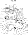
FIG. 10 is an exploded perspective view of a spinal implant in accordance with another embodiment of the present invention. -
FIG. 11A is a side cross-sectional view of the spinal implant ofFIG. 10 , taken along the longitudinal axis of thefirst arm 12. -
FIG. 11B is a cross-sectional plan view of the spinal implant ofFIG. 10 , taken along the longitudinal axis of thefirst arm 12. -
FIG. 12A is cross-sectional plan view of the spinal implant ofFIG. 10 , taken along thechannel 66 in thesecond arm 14. -
FIG. 12B is a top perspective view of the spinal implant ofFIG. 10 in a laterally expanded configuration and connected to the delivery tool. -
FIG. 12C is a bottom perspective view of the spinal implant ofFIG. 10 in a laterally expanded configuration and connected to the delivery tool. -
FIG. 12D is an enlarged perspective view of the spinal implant ofFIG. 10 in a laterally expanded configuration, with thepivotable arm 23 of the delivery tool in engagement with apin 25 of thesecond arm 14. -
FIG. 13 is a partially exploded perspective view of a spinal implant in accordance with another embodiment of the present invention. -
FIG. 14 is a perspective view of the spinal implant ofFIG. 13 positioned in an intervertebral space. -
FIG. 15 is a top plan view of the spinal implant ofFIG. 13 during insertion into the intervertebral space. -
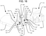
FIG. 16 is a perspective cross-sectional view of the spinal implant ofFIG. 13 , taken along line 16-16. -
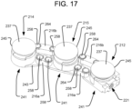
FIG. 17 is a perspective view of a spinal implant in accordance with another embodiment of the present invention. -
FIG. 18 is a top perspective view of the spinal implant ofFIG. 17 during insertion into an intervertebral space. -
FIG. 19 is a top perspective view of the spinal implant ofFIG. 17 positioned in an intervertebral space. -
FIG. 20 is a cross-sectional bottom plan view of the spinal implant ofFIG. 19 taken along thebottom plates 243 of the implant. -
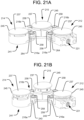
FIG. 21A is a perspective view of the spinal implant ofFIG. 17 in a longitudinally contracted configuration. -
FIG. 21B is a perspective view of the spinal implant ofFIG. 17 in a longitudinally expanded configuration. -
FIG. 22A is a top plan view of the spinal implant ofFIG 17 . -
FIG. 22B is a side cross-sectional view of the spinal implant ofFIG. 22A taken along line 22-22. -
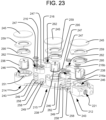
FIG. 23 is an exploded view of the spinal implant ofFIG. 17 . -
FIG. 24 is a partial, perspective side cross-sectional view of the spinal implant ofFIG. 22A taken along line 24-24, with thetop plate 245 omitted. -
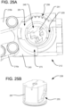
FIG. 25A is a partial top perspective view of onesegment 212 of the spinal implant ofFIG. 17 with the piston, cam ring, and ratcheting ring omitted. -
FIG. 25B is a perspective view of a piston of the spinal implant ofFIG. 17 . -
FIG. 25C is a perspective view of a cam ring of the spinal implant ofFIG. 17 . -
FIG. 25D is a perspective view of a ratcheting ring of the spinal implant ofFIG. 17 . -
FIG. 26 is a partial, exploded perspective view of the spinal implant ofFIG. 17 , with thetop plate 245 omitted. -
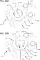
FIG. 27A is a partial perspective view of the spinal implant ofFIG. 17 , with thetop plate 245 omitted, in longitudinally contracted configuration. -
FIG. 27B is a partial perspective view of the spinal implant ofFIG. 17 , with thetop plate 245 omitted, in a longitudinally expanded configuration. -
FIG. 28A is partial perspective view of the spinal implant ofFIG. 17 in a longitudinally contracted configuration. -
FIG. 28B is a partial perspective view of the spinal implant ofFIG. 17 in a longitudinally expanded configuration. -
FIG. 29A is a perspective view of a subassembly of the spinal implant ofFIG. 17 , showing the piston, ratcheting ring, and control cable. -
FIG. 29B is a partial top plan view of the spinal implant ofFIG. 17 with thetop plate 245 omitted. -
FIG. 29C is a partial, exploded perspective view of the spinal implant ofFIG. 17 . - When referring to specific directions in the following disclosure, it should be understood that, as used herein, the term "proximal" means closer to the operator/surgeon, and the term "distal" means further away from the operator/surgeon. The term "anterior" means toward the front of the body or the face, and the term "posterior" means toward the back of the body. With respect to the longitudinal axis of the spine, the term "superior" refers to the direction towards the head, and the term "inferior" refers to the direction towards the pelvis and feet. Finally, the term "lateral" or "laterally," as used below, refers to a direction or movement that is in the transverse plane, which is orthogonal to the longitudinal axis of the spine.
-
FIG. 1 illustrates animplant 10 in accordance with one embodiment of the present invention. Theimplant 10 includes two segments articulatable with respect to one another, in the form of afirst arm 12 and asecond arm 14. Specifically, the first andsecond arms hinge portion 16. Theimplant 10 is insertable into an intervertebral space in a closed configuration, as illustrated inFIGS. 2A-3A and4A , and theimplant 10 can be expanded laterally within the intervertebral space by articulating thearms hinge portion 16, as shown inFIGS. 3B and4B . - The insertion of the
implant 10 into the intervertebral space can be performed by adelivery tool 18 securely attachable to theproximal end 20 of theimplant 10 via an anchor located on theimplant 10. The anchor may be in the form of a threadedbore 21 for receiving a correspondingly threaded portion at thedistal end 22 of thedelivery tool 18, and the threaded bore 21 may be located on thefirst arm 12. Thedelivery tool 18 may also be responsible for expanding theimplant 10 laterally. For example, as shown inFIGS. 2A-B , thedistal end 22 of thedelivery tool 18 may include aspreader 24 having atab 26 with an angleddistal surface 28. Thespreader 24 may be guided for longitudinal movement with respect to thedelivery tool 18 by atrack 30, and that longitudinal movement of thespreader 24 may be controlled by acontrol arm 32 towards the proximal end of thespreader 24. Thecontrol arm 32 may be directly grasped by a surgeon and pushed distally or pulled proximally in order to induce corresponding longitudinal movement of thespreader 24 with respect to thedelivery tool 18, or thecontrol arm 32 may be engaged by another component (e.g., a proximally extending control cable) that can be advanced or retracted in order to induce the longitudinal movement of thespreader 24. As shown inFIG. 3A , the angleddistal surface 28 of thespreader 24 is configured to contact anengagement surface 34 of the implant when thespreader 24 is advanced distally, such that the distal movement of the angleddistal surface 28 pushes on theengagement surface 34 and causes thesecond arm 14 to articulate with respect to thefirst arm 12 about thehinge portion 16, which may be located at thedistal end 36 of theimplant 10. As shown inFIGS. 1 and3B , theengagement surface 34 may be angled, for example by having an angle that matches the angle of the angleddistal surface 28 of thespreader 24. - After the
implant 10 has been laterally expanded to the desired configuration, theimplant 10 can also be expanded longitudinally in the superior-inferior direction, as shown inFIG. 5B . Specifically, theimplant 10 can be expanded such that one or more uppervertebral engaging surfaces 37 on thetop end 39 of theimplant 10 are moved apart from one or more lowervertebral engaging surfaces 41 on thebottom end 43 of theimplant 10. Such longitudinal expansion can cause theimplant 10 to securely engage the vertebral body Vs in the superior direction and the vertebral body Vi in the inferior direction, and further expansion can result in some movement of the superior vertebral body Vs and the inferior vertebral body Vi away from one another, such that at least some distraction of the intervertebral space results. - The longitudinal expansion of the implant may be performed using various means, including bellows, rotating cam lift mechanisms, rotating screw lift mechanisms, or other such devices, as disclosed in the '620 Patent. The longitudinal expansion may also be driven by hydraulics, as disclosed in the '620 Patent and the `513 Application, and as discussed below in connection with the various illustrated embodiments. For example, the
implant 10 may include one or more pistons received within associated cylinders and driven to translate outwardly along the longitudinal axis of the spine by hydraulic pressure, thus resulting in longitudinal expansion of the implant. The pistons may haveplate portions 45 at their top ends that may include the uppervertebral engaging surfaces 37 thereon for contacting and applying expansion force to the superior vertebral body Vs. Alternatively, the top ends of the pistons may simply be defined as the uppervertebral engaging surfaces 37 and configured to directly engage the superior vertebral body Vs. Although not shown in the drawings herein, the vertebral engaging surfaces of the embodiments disclosed herein may be smooth surfaces, or they may include textural features (e.g., protrusions, ridges, etc.) for more securely interfacing with the engaged vertebrae, or they may include spikes or similar features (which can either be fixed or deployable after implantation) for penetrating into the engaged vertebrae. - As shown in the embodiment of
FIGS. 1-9 , theimplant 10 may include afirst piston 38 on thefirst arm 12, asecond piston 40 on thesecond arm 14, and acentral piston 42 at thehinge portion 16. The pistons may be individually controlled via separate hydraulic pressure channels formed within the implant, or, as in the embodiment ofFIGS. 1-9 , they may be controlled by a common hydraulic pressure channel. Specifically, achannel 44 formed within thefirst arm 12 may communicate with thecylinder 46 within which thefirst piston 38 is disposed. That way, hydraulic fluid within thechannel 44 may cause outward expansion of thefirst piston 38. A seal member, which may be in the form of an o-ring 47a, may be provided between thefirst piston 38 and the associatedcylinder 46, so that those components can slide with respect to one another while preventing hydraulic fluid from escaping at that interface. Thechannel 44 may communicate with an opening so as to be supplied with pressurized hydraulic fluid from thedelivery tool 18. For example, thechannel 44 may communicate with thebore 21, so that the hydraulic fluid may be supplied to thechannel 44 by aconduit 48 in thedelivery tool 18. The supply for the hydraulic fluid need not be provided through thesame bore 21 used to anchor theimplant 10 to thedelivery tool 18, however, and alternative embodiments may, for example, include a separate opening in the outer surface of the implant for communication with aconduit 48 of thedelivery tool 18. - The
channel 44 may also communicate with thecylinder 50 within which thecentral piston 42 is disposed, so that the hydraulic fluid may also cause outward expansion of thecentral piston 42. The communication between thechannel 44 and thecylinder 50 may either be direct communication or communication via an intervening pathway, such as viaangled channel 52 illustrated inFIG. 6 .Channel 52 may be formed by drilling an angled bore from outside thefirst arm 12 to the distal end of thecylinder 50, such that the bore intersects thechannel 44. If formed in that manner, theextraneous end 54 of thechannel 52 may subsequently be plugged, so that the hydraulic fluid does not escape theimplant 10 via that path. A seal member, which may be in the form of an o-ring 47b, may be provided between thecentral piston 42 and the associatedcylinder 50, so that those components can slide with respect to one another while preventing hydraulic fluid from escaping at that interface. - The articulating connection between the
first arm 12 and thesecond arm 14 athinge portion 16 may be constructed so as to allow for the communication of the hydraulic fluid between thefirst arm 12 and thesecond arm 14. For example, as shown inFIG. 9 , thesecond arm 14 includes acircular plate 56 at thedistal end 36 of theimplant 10. That circular plate includes apost 58 projecting perpendicular thereto. Thefirst arm 12 has acylindrical portion 60 corresponding to the shape of thecircular plate 56 and having anopening 62 in the bottom surface thereof for receiving thepost 58 therethrough, as shown inFIG. 7 . The interconnection of thepost 58 of thesecond arm 14 within theopening 62 of thefirst arm 12 allows the first andsecond arms post 58. In order to rotationally secure the first andsecond arms bushing 64 may be secured (e.g., press fit) onto thepost 58 after it has been received through theopening 62, so as to prevent thepost 58 from withdrawing from theopening 62 while allowing for pivoting between those components. - In order to accommodate flow of the hydraulic fluid through the
hinge portion 16 between thefirst arm 12 and thesecond arm 14, thepost 58 may be hollow, so as to communicate with the interior of thecylinder 50. Additionally, to allow for pivoting about thepost 58 while preventing hydraulic fluid from escaping at its interface with theopening 62, a seal member, which may be in the form of an o-ring 47-c, may be provided at that interface, such as by positioning the seal member around thepost 58 between the bottom surface of thefirst arm 12 and thebushing 64. - The
hollow post 58 in thesecond arm 14 may communicate with achannel 66 in thesecond arm 14 that also communicates with thecylinder 68 within which thesecond piston 40 is disposed, so that the hydraulic fluid may also drive the outward expansion of thesecond piston 40. Thechannel 66 may be formed by drilling a bore along thesecond arm 14 from theproximal end 20 of theimplant 10. If formed in that manner, theextraneous end 67 of thechannel 66 may subsequently be plugged, so that the hydraulic fluid does not escape theimplant 10 via that path. So that thepiston 40 can slide with respect to thecylinder 68 without allowing hydraulic fluid to escape at that interface, a seal member, which may be in the form of an o-ring 47d, may be provided between thesecond piston 40 and the associatedcylinder 68 in the same manner as illustrated inFIG. 6 with respect to thefirst piston 38 and associatedcylinder 46. - The
implant 10 may include a locking system to lock the positions of the pistons, at least by preventing them from retracting back into the cylinders once expanded. For example, the pistons may include ratcheting components that allow the pistons to move in the expansion direction, but automatically resist retraction of the pistons in the opposite direction. Such ratcheting components may also be selectively unlockable, in order to allow the pistons to retract when desired. One embodiment of such ratcheting components is shown in the embodiment of the implant illustrated inFIGS. 1-9 and will now be discussed. - As shown in
FIG. 9 , the first andsecond pistons vertical posts respective bores implant 10. Those bores 69, 71 desirably help constrain the rotational orientation of the associatedpistons pistons posts teeth 74 therealong. Correspondingpawls teeth 74, as shown inFIG. 1 , so as to permit thepistons pistons pawls recesses implant 10. Thepawls recesses respective retaining plates implant 10. Arespective control cable pawls holes control cables implant 10 withinrespective grooves control cables delivery tool 18, where they can be controlled by the surgeon via thedelivery tool 18. Linear compression springs (not shown) are received around thecontrol cables recess pawls recesses teeth 74. Thus, when thecables respective pawls respective recesses vertical posts teeth 74 and allowing thepistons central piston 42 can similarly be controlled by a correspondingpawl 88 received within arecess 89 in the outer surface of theimplant 10 and held there by a retainingplate 90 affixed to the outer surface of the implant. Thepawl 88 is biased by a spring (not shown) into engagement with ratchetingteeth 74 on the outer surface of thepiston 42, and thepawl 88 can be disengaged from the ratchetingteeth 74 of thepiston 42 by thesame control cable 82 that controlspawl 76, which controlcable 82 connects to thepawl 76 via connectinghole 91. As thecontrol cable 83 that controlspawl 77 extends all the way around the outside of theimplant 10, it can pass throughholes 92 inpawls central piston 42 may also include avertical post 93 received within abore 94 in theimplant 10 to help constrain the rotational orientation of thepiston 42 and help guide the expansion of thepiston 42 along a linear path. - Other alternative locking systems are possible, however. For example, rotatable, inter-engaging locking elements having tiered, multi-stepped support surfaces, as disclosed in the '620 Patent and the `513 Application, can be used. That is, as illustrated in
FIGS. 10-11 , eachpiston upper lock support 53a-c that is structured to releasably engage an associatedlower lock support 51a-c. The upper lock supports 53a-c may each resemble an inverted spiral staircase integrally formed inside therespective piston respective cylinder piston respective cylinder pistons - Each of the lower lock supports 51a-c can be unlocked when desired, by rotating the lower lock supports away from engagement with the corresponding upper lock supports, such that the
pistons lower lock support 51a-c may includegear teeth 35 so as to form a pinion engageable by a corresponding,translatable rack gear 33a-c. Eachrack gear 33a-c is biased by a correspondinglinear spring 31a-c, which provides the rotational biasing force that drives each of the lower lock supports 51a-c into engagement against the associated upper lock supports 53a-c. The unlocking of any one of the lower lock supports 51a-c may thus include pushing the associatedrack gear 33a-c to rotate the lower lock support out of engagement with the upper lock support, which further compresses the associatedspring 31a-c. In thefirst arm 12,lower lock support 51a is engaged byrack gear 33a, andlower lock support 51c is engaged byrack gear 33c. Both of those rack gears 33a, 33c may includeengagement plates 29 at their proximal ends, so that the associated lower lock supports 51a, 51c can be unlocked by pushing theengagement plates 29, and thus the rack gears, in the distal direction. The rack gears 33a, 33c may be positioned within thehydraulic channel 44 formed within thefirst arm 12, such that theengagement plates 29 are accessible via thebore 21, as shown inFIG. 11A . Thus, thedelivery tool 18 can include appropriately structured components (not shown) designed to move distally into thebore 21 and push the corresponding rack gears 33a, 33c. Thelower lock support 51b in thesecond arm 14 is engaged byrack gear 33b, such that thelower lock support 51b may be unlocked by moving therack gear 33b in the proximal direction. Thatrack gear 33b may be positioned within the hydraulic channel 66 (or some other channel) formed within thesecond arm 14, and therack gear 33b may be engaged from the exterior of thesecond arm 14 to induce the unlocking movement of therack gear 33b. For example, apiston 27 positioned within thechannel 66 and connected to therack gear 33b may include apin 25 projecting laterally through a slot along theinner surface 15 of thesecond arm 14. Thatpin 25 may be 14 engaged by a tool connected to or associated with thefirst arm 12. For example, thespreader 24, or a similar component movable distally along the inner side of thefirst arm 12, may include apivotable arm 23 for engaging thepin 25. Thearm 23 may designed to pivot such that it can slide thepin 25 proximally along thesecond arm 14, so as to push therack gear 33b proximally and unlock thelower lock support 51b, as shown inFIGS. 12A-D . That proximal movement of therack gear 33b results in a further compression of thespring 31b positioned between therack gear 33b and a pluggingcap 63 at theend 67 of thechannel 66. In the embodiment illustrated inFIGS. 10-12 , the upper and lower lock supports are located inside the respective pistons. However, alternative arrangements in which the lock supports are positioned outside of the respective pistons and at least partially encircle the pistons, as disclosed in the '620 Patent, may also be used. - As discussed above, the
pistons FIGS. 1-9 . One benefit of having all of thepistons implant 10. Moreover, with a single hydraulic pressure channel, theimplant 10 may be designed such that thepistons pistons central piston 42 vis-à-vis the first andsecond pistons 38, 40 (where the first and second pistons have the same area). It is noted that the force ratios provided in the below table are the ratio of the force applied by the first andsecond pistons central piston 42.Diameter of central piston 42 (mm) Diameter of first and second pistons 38, 40 (mm)Area of central piston 42 (mm2) Area of first and second pistons 38, 40 (mm2)Force ratio (first and second pistons 38, 40 : central piston 42)5 3 314.16 113.10 0.72 6 3 452.39 113.10 0.50 7 3 615.75 113.10 0.37 5 4 314.16 201.06 1.28 6 4 452.39 201.06 0.89 7 4 615.75 201.06 0.65 5 5 314.16 314.16 2.00 6 5 452.39 314.16 1.39 7 5 615.75 314.16 1.02 9 3 1017.88 113.10 0.22 9 4.5 1017.88 254.47 0.5 9 6 1017.88 452.39 0.89 7.6 3 725.83 113.10 0.31 7.6 4 725.83 201.06 0.55 7.6 5 725.83 314.16 0.87 - Desirably, by applying different forces at different locations along the
implant 10, the implant can create different amounts of expansion at those different locations. Beneficially, such differential expansion can be used for lordosis correction. For example, the nerve roots can be decompressed by providing some expansion at the posterior portion of the spine, and lordosis can be corrected by providing a greater amount of expansion at the anterior portion of the spine. - Another embodiment of an
implant 110 having afirst segment 112 andsecond segment 114 in accordance with the present invention is illustrated inFIGS. 13-16 . In that embodiment, rather than the twosegments implant 110 being in the form of long and narrow first and second arms, as shown in the above-discussed figures of the previous embodiments, the twosegments segments segment cylindrical opening 162 at each end sized to receive arespective post 158 connected to each of thesegments 112, 114 (e.g., connected to the bottom plates 143), so that the linkages 116 are pivotable about theposts 158. Moreover,bushings 164 may be secured (e.g., press fit) onto theposts 158 after they have been received through theopenings 162, so as to prevent theposts 158 from withdrawing from theopenings 162 while allowing for pivoting between those components. As shown inFIG. 13 , one of thelinkages 116a may be astraight link 116a connecting the left proximal corner of thesecond segment 114 to a distal end of thefirst segment 112, either centrally located in the left/right direction or towards the right side of thefirst segment 112. Anotherlinkage 116b may connect the right proximal corner of thesecond segment 114 to a left side of thefirst segment 112, proximally of the distal end. Thatsecond linkage 116b may have a bent profile (e.g., with a 90° bend), so as to avoid interference with thefirst linkage 116a. In other alternative embodiments, straight linkages (such as those illustrated in the embodiment ofFIGS. 17-22 ), crossing linkages (not shown), or other suitable linkage arrangements may be used. - Each
segment implant 110 may comprise atop plate 145 having an uppervertebral engaging surface 137 and abottom plate 143 having a lowervertebral engaging surface 41. Hydraulically drivenpistons 138 received in correspondingcylinders 146, similar to those discussed above, can be positioned between the top andbottom plates segments bottom plates segment FIGS. 23-29 . - Either or both of the
linkages second segments implant 110 may be configured to transmit the hydraulic fluid therethrough, so that a single hydraulic pressure channel may be common to the expansion mechanisms (e.g., pistons/cylinders) of bothsegments cylinders 146 within which thepistons 138 are disposed may be interconnected by a series of channels, which may be formed in thebottom plate 143. Those channels formed in thefirst segment 112 may communicate with one or bothposts 158 of thefirst segment 112. For example, as shown inFIG. 16 , theposts 158 of thefirst segment 112 may be hollow so as to define afluid channel 144 therein. Thelinkages fluid channel 165 therein. Finally, theposts 158 of thesecond segment 114 may also be hollow so as to define afluid channel 166 therein, which channel 166 may communicate either directly or indirectly with the cylinder of thesecond segment 112. In order for the hydraulic fluid to flow between thefluid channels posts 158 and thefluid channels 165 of thelinkages slots 152 may be provided in each of theposts 158. Moreover, seal members, which may be in the form of o-rings 147, may be positioned in correspondinggrooves 149 of theposts 158, both above and below theslots 152, so as to seal the network of fluid channels defined within the linkages 116 while allowing the linkages to pivot. - Desirably, the linkages 116 of the
implant 110 may be configured so as to allow the first andsecond segments FIG. 13 . That way, theimplant 110 may beneficially take up a small area in the lateral direction during insertion, after which the implant may be articulated within the intervertebral space to achieve a final configuration like that illustrated inFIG. 12 , which may be towards the anterior portion of the spine. Although the embodiment of theimplant 10 discussed above in connection withFIGS. 1-9 was shown being inserted withhinge portion 16 leading and the first andsecond arms second arms FIG. 15 . Specifically, thearms implant 10 may initially be spread apart such that they are positioned on opposite sides of thehinge portion 16. - Another embodiment of an implant 210 in accordance with the present invention and illustrated in
FIGS. 17-29 may be similar to theimplant 110 illustrated inFIGS. 13-16 , but the implant 210 ofFIGS. 17-29 may have three articulatingsegments FIGS. 17-29 similar to those used in the embodiment ofFIGS. 13-16 refer to analogous elements, and thus such analogous elements may not be separately discussed below in connection with implant 210 ofFIGS. 17-29 . - The three
segments pivotable linkages 216 like those inimplant 110, except that those illustrated in the embodiment ofFIGS. 17-29 are allstraight linkages 216. Having three (or more) interconnected, articulatingsegments FIG. 18 , after which the implant 210 can be articulated into an arrangement like that illustrated inFIG. 19 . That is, thesegments FIG. 18 ), after which the segments may be articulated within the intervertebral space to create a more triangular arrangement of pistons (as illustrated inFIG. 19 ), with the entire implant 210 being disposed towards the anterior portion of the spine. Thebottom plates 243 of eachsegment notches 206 configured to receive portions of thebottom plates 243 of adj acent segments, as shown inFIG. 20 , in order to facilitate the articulation of the segments into the triangular arrangement shown inFIG. 19 . The implant 210 may then be expanded in the longitudinal direction of the spine (e.g., hydraulically) from the contracted configuration illustrated inFIG. 21A to the expanded configuration illustrated inFIG. 21B . As shown inFIG. 22B , any or all of thelinkages 216 may be configured in the same manner as the linkages 116 of the embodiment ofFIGS. 13-16 , such that thelinkages 216 can communicate the hydraulic fluid among all of thesegments channels 207 formed in thebottom plates 243. - In the embodiments of
FIG. 13-16 and17 -29, one ormore pistons 238 may be independently controlled via a separate pressure channel. Thedifferent linkages 116, 216 may thus be on different pressure channel circuits that bypass certain pistons. As an example, in an embodiment having three segments such as that shown inFIGS. 17-29 , the pressure channel communicating with theinner linkages 216a may bypass thepiston 238 of thecentral segment 215, while communicating with thepistons 238 of theother segments outer linkages 216b may only serve thepiston 238 of thecentral segment 215, while bypassing thepistons 238 of the other segments. Other embodiments may include any other combinations of pistons on different pressure channels. - The embodiment of
FIGS. 17-29 may include a different locking system to lock the positions of thepistons 238 than those discussed above. That is, as shown inFIGS. 23-29 , the locking system of eachsegment lower lock support 251 coupled with thebottom plate 243, which lower lock support is movably engageable with an associatedupper lock support 253 coupled to the expandingtop plate 245. Like the upper lock supports 53a-c of the embodiment ofFIGS. 10-11 , the upper lock supports 253 of the embodiment ofFIGS. 17-29 are integrally formed inside therespective pistons 238 and resemble an inverted spiral staircase. The lower lock supports 251 may also resemble an upright spiral staircase positioned within therespective cylinders 246. Unlike the embodiment ofFIGS. 10-11 , however, the lower lock supports 251 of the embodiment ofFIGS. 17-29 are integrally formed within therespective cylinders 246. The upper and lower lock supports may thus be movably engageable with one another via rotation of thepistons 238 during expansion. Specifically, the outer surface of eachpiston 238 may include acam profile 255 shaped for engagement with acam follower pin 257 of acam ring 259 that surrounds thepiston 238 and is secured tocylinder 246. As shown inFIGS. 25A ,26 , and27A-B , the top end of thecylinder 246 may include arecess 261 shaped to receive thecam ring 259, and aprojection 273 of thecam ring 259 may be shaped to be received within acorresponding relief 275 of thecylinder 246, so as to lock the rotational orientation of thecam ring 259. The engagement of thecam follower pin 257 and thecam profile 255 is such that, as one of the steps of theupper lock support 253 is displaced vertically above a corresponding step of thelower lock support 251 during expansion of thepiston 238, thecam ring 259 causes thepiston 238 to rotate (counterclockwise in the view shown inFIGS. 27-28 ) so that the step of theupper lock support 253 is moved into engagement with the next step up along thelower lock support 251. That action then continues for each successive step of the upper and lower lock support during the upward expansion of thepiston 238. The vertical displacement of thepiston 238 thus becomes locked at each successive step, since retraction of thepiston 238 will cause the aligned steps of the upper and lower lock supports to engage, thereby preventing further downward movement of thepiston 238. - The
piston 238 may be controlled during expansion so that it is only permitted to rotate in a single direction, such as by a ratcheting mechanism. That way, when the expansion force is released from thepiston 238, the piston will not be permitted to undo its rotation so as to retract more than the height of a single step of the upper and lower lock supports. The ratcheting mechanism may include aratcheting ring 295 surrounding thepiston 238 and fixed rotationally with respect to thepiston 238. Specifically, theratcheting ring 295 may include one ormore keys 296 receivable within associatedkey slots 297 on thepiston 238, so that theratcheting ring 295 can maintain its vertical position with respect to thecylinder 246 while theratcheting ring 295 rotates with thepiston 238 as the piston expands upwardly. During that rotation, a ratchetingpawl 298 along the perimeter of theratcheting ring 295 engages ratchetingteeth 299 formed along thecylinder 246. In the embodiment illustrated inFIGS. 27-28 , theratcheting ring 295 permits counterclockwise rotation of thepiston 238 while resisting clockwise rotation of thepiston 238. As shown inFIGS. 24 ,25A 26 , and29C , theratcheting ring 295 is received within anarcuate groove 205 at the top end of thecylinder 246, in order to constrain the position of the ratcheting ring about the longitudinal axis of thepiston 238 while permitting the ratcheting ring to rotate about that axis, and the vertical position of theratcheting ring 295 is constrained between thecam ring 259 and the top of thecylinder 246. - If retraction of the
pistons 238 is desired by the user, theratcheting ring 295 can be unlocked so as to permit the rotation of the pistons to be reversed. Specifically, as shown inFIGS. 29A-C , acontrol cable 282 is received within agroove 286 in the ratchetingpawl 298, and the distal end of thecontrol cable 282 may be fixed to theratcheting ring 295 by anenlarged ball 209 received within acorresponding recess 208. By pulling proximally on thecontrol cable 282, the ratchetingpawl 298 will deflect out of engagement with the ratchetingteeth 299 of thecylinder 246, as shown inFIG. 29B , thus permitting reverse rotation of thepiston 238. Preferably, theratcheting ring 295 of eachsegment respective control cable 282 extending proximally from the implant 210 for operation by the user. That way, thepistons 238 can be individually retracted, if desired. Alternatively, all of the ratcheting rings 295 may be interconnected for simultaneous unlocking, such as by having each of the ratcheting rings 295 connected to a single control cable, or by utilizing a series of control cables interconnecting the ratcheting rings 295 of eachsegment - In order to avoid imparting the rotation of the
pistons 238 to the vertebral bodies via the outwardly expandingtop plates 245 that define the uppervertebral engaging surfaces 237, thetop plates 245 may be connected to therespective pistons 238 by connections which permit rotation between those two components. For example, thetop plates 245 may be connected to the associatedpistons 238 via ball joints 204. Beneficially, such ball joint connections may also permit thetop plates 245 to be angled with respect to thepistons 238 as needed, based on any angle defined between the vertebral body engaged by the top plates 245 (e.g., the vertebral body Vs in the superior direction) and thebottom plates 243 defining the lower vertebral engaging surfaces 241. - Although not illustrated herein, the embodiment of the locking system shown in
FIGS. 23- 29 may be used in place of any of the other locking systems of the other embodiments disclosed in the present application. Moreover, pivotable connections (such as the ball joint 204 connections discussed above in connection with the embodiment ofFIGS. 17-29 ) may be incorporated between the top plates and their associated pistons in any of the other embodiments of the present application. - Although it is possible to do so in an embodiment having two expandable segments (like that illustrated in
FIGS. 13-16 ), is may be more desirable in an embodiment having three or more segments (like that illustrated inFIGS. 17-29 ) to have differently sized pistons interconnected by a common pressure channel, such that differential expanding forces can be applied, as discussed above in connection with the embodiment ofFIGS. 1-9 . For example, in the implant 210 ofFIGS. 17-29 , thecentral segment 215 may beneficially have a piston sized differently from the other twosegments 212, 214 (which may have the same sizes as one another) in order to correct lordosis by applying a different (e.g., greater) amount of expansion at the anterior portion of the spine when the implant 210 is arranged in the manner illustrated inFIG. 19 . - Any of the embodiments disclosed above may be used in any type of approach to the intervertebral space (e.g., PLIF, TLIF, and lateral), although certain approaches may be more preferred for certain implant configurations. For example, the embodiments of
FIGS. 1-11 may be best suited for a PLIF approach, while the embodiments ofFIGS. 13-29 may be best suited for a TLIF approach. - Although various sealing members (e.g., o-rings) have been disclosed above for maintaining seals between surfaces that move relative to one another, it is noted that alternative embodiments (not shown) need not include separate sealing members, and instead either or both of the movable components may be structured to be self sealing.
- Although the invention herein has been described with reference to particular embodiments, it is to be understood that these embodiments are merely illustrative of the principles and applications of the present invention. It is therefore to be understood that numerous modifications may be made to the illustrative embodiments and that other arrangements may be devised.
Claims (10)
- A spinal implant (10, 110, 210) for placement in an intervertebral space between a first vertebral body (Vi) and a second vertebral body (Vs) of a spine, the spinal implant comprising:a body (43, 143, 243) having a first surface (41, 141, 241) for contacting the first vertebral body;a first extendable support element connected to the body at a first location, the first extendable support element including a first piston (42, 138, 238) slidably received within a first cylinder (50, 146, 246), and the first extendable support element being configured to expand so as to apply a first expansion force directed away from the first surface;a second extendable support element connected to the body at a second location, the second extendable support element including a second piston (38, 138, 238) slidably received within a second cylinder (46, 146, 246), and the second extendable support element being configured to expand so as to apply a second expansion force directed away from the first surface; andan input (21) for expanding the first and second extendable support elements,wherein the first and second extendable support elements are configured to be extended by supplying a hydraulic fluid to the input, andwherein the spinal implant is configured such that application of a single input force to the spinal implant via the input induces the first extendable support element to expand and apply the first expansion force and induces the second extendable support element to expand and apply the second expansion force, the first expansion force being greater than the second expansion force.
- The spinal implant of claim 1, wherein the first piston (42, 138, 238) has a larger cross-sectional area than the second piston (38, 138, 238).
- The spinal implant of claim 2, wherein the spinal implant includes a first portion (12) and a second portion (14) articulatable about a hinge portion (16).
- The spinal implant of claim 3, wherein the first piston (42) is located on the hinge portion (16).
- The spinal implant of claim 4, wherein the second piston (38) is located on one of the first and second portions (12, 14) of the spinal implant.
- The spinal implant of claim 5, further comprising a third piston (40) slidably received within a third cylinder (68), wherein the second piston (38) is located on the first portion (12) of the spinal implant and the third piston (40) is located on the second portion (14) of the spinal implant.
- The spinal implant of claim 6, wherein the first piston (42) has a larger cross-sectional area than both the second piston (38) and the third piston (40).
- The spinal implant of any one of claims 3-7, wherein the first and second extendable support elements are configured to be extended by supplying a hydraulic fluid to the input (21), wherein the input (21) is disposed on the first portion (12) of the spinal implant opposite the hinge portion (16).
- The spinal implant of claim 8, wherein the spinal implant is configured to direct the hydraulic fluid from the input (21) in the first portion (12) to the second portion (14) via the hinge portion (16).
- The spinal implant of claim 2, wherein the spinal implant includes a first segment (212), a second segment (215), and a third segment (214), the first segment (212) being articulatably connected to the second segment (215) and the third segment (214) being articulatably connected to the second segment (215), such that the second segment (215) is located between the first segment (212) and the third segment (214); wherein the first piston (238) is located on the second segment (215).
Applications Claiming Priority (1)
| Application Number | Priority Date | Filing Date | Title |
|---|---|---|---|
| US201662413038P | 2016-10-26 | 2016-10-26 |
Publications (2)
| Publication Number | Publication Date |
|---|---|
| EP3315096A1 EP3315096A1 (en) | 2018-05-02 |
| EP3315096B1 true EP3315096B1 (en) | 2023-08-16 |
Family
ID=60186200
Family Applications (1)
| Application Number | Title | Priority Date | Filing Date |
|---|---|---|---|
| EP17198694.6A Active EP3315096B1 (en) | 2016-10-26 | 2017-10-26 | Expandable interbody implant with lateral articulation |
Country Status (4)
| Country | Link |
|---|---|
| US (3) | US10485675B2 (en) |
| EP (1) | EP3315096B1 (en) |
| JP (1) | JP7202067B2 (en) |
| AU (1) | AU2017251734B2 (en) |
Families Citing this family (20)
| Publication number | Priority date | Publication date | Assignee | Title |
|---|---|---|---|---|
| US9265620B2 (en) | 2011-03-18 | 2016-02-23 | Raed M. Ali, M.D., Inc. | Devices and methods for transpedicular stabilization of the spine |
| US8663332B1 (en) | 2012-12-13 | 2014-03-04 | Ouroboros Medical, Inc. | Bone graft distribution system |
| US10687962B2 (en) | 2013-03-14 | 2020-06-23 | Raed M. Ali, M.D., Inc. | Interbody fusion devices, systems and methods |
| KR20160010862A (en) | 2013-03-14 | 2016-01-28 | 라에드 엠. 알리, 엠.디., 인크. | Lateral interbody fusion devices, systems and methods |
| US9186259B2 (en) | 2013-09-09 | 2015-11-17 | Ouroboros Medical, Inc. | Expandable trials |
| US9060876B1 (en) | 2015-01-20 | 2015-06-23 | Ouroboros Medical, Inc. | Stabilized intervertebral scaffolding systems |
| EP3292841B8 (en) | 2016-09-12 | 2023-05-31 | Howmedica Osteonics Corp. | Interbody implant with independent control of expansion at multiple locations |
| US9883953B1 (en) | 2016-09-21 | 2018-02-06 | Integrity Implants Inc. | Stabilized laterovertically-expanding fusion cage systems with tensioner |
| AU2017251734B2 (en) * | 2016-10-26 | 2022-10-20 | Howmedica Osteonics Corp. | Expandable interbody implant with lateral articulation |
| US11033401B2 (en) | 2017-01-10 | 2021-06-15 | Integrity Implants Inc. | Expandable intervertebral fusion device |
| WO2019023251A1 (en) | 2017-07-24 | 2019-01-31 | Integrity Implants, Inc. | Surgical implant and related methods |
| EP3742990A4 (en) | 2018-03-01 | 2021-11-24 | Integrity Implants Inc. | Expandable fusion device with independent expansion systems |
| KR102379915B1 (en) * | 2020-03-18 | 2022-03-29 | 주식회사 엔닥 | Cage for minimal invasive surgery |
| US11816831B2 (en) * | 2020-04-29 | 2023-11-14 | Medtronic Navigation, Inc. | System and method for navigating and illustrating a procedure |
| US11890060B2 (en) | 2020-04-29 | 2024-02-06 | Medtronic Navigation, Inc. | System and method for navigating and illustrating a procedure |
| KR20220017092A (en) * | 2020-08-04 | 2022-02-11 | 임병철 | Intervertebral cage |
| EP4358904A1 (en) * | 2021-06-22 | 2024-05-01 | Musc Foundation for Research Development | Articulating expandable device |
| US20230023449A1 (en) * | 2021-07-20 | 2023-01-26 | Globus Medical, Inc. | Interlaminar lumbar interbody fusion system and associated robotic systems |
| US11534309B1 (en) * | 2021-07-20 | 2022-12-27 | Globus Medical Inc. | Interlaminar lumbar interbody fusion implants, intradiscal implants, instruments, and methods |
| US11730606B2 (en) | 2021-12-22 | 2023-08-22 | Ctl Biotec, Corporation | Expandable bi-dimensional interbody and method of manufacturing the same |
Family Cites Families (222)
| Publication number | Priority date | Publication date | Assignee | Title |
|---|---|---|---|---|
| US3875595A (en) | 1974-04-15 | 1975-04-08 | Edward C Froning | Intervertebral disc prosthesis and instruments for locating same |
| US7452359B1 (en) | 1988-06-13 | 2008-11-18 | Warsaw Orthopedic, Inc. | Apparatus for inserting spinal implants |
| US4969888A (en) | 1989-02-09 | 1990-11-13 | Arie Scholten | Surgical protocol for fixation of osteoporotic bone using inflatable device |
| US4932975A (en) | 1989-10-16 | 1990-06-12 | Vanderbilt University | Vertebral prosthesis |
| US5236460A (en) | 1990-02-12 | 1993-08-17 | Midas Rex Pneumatic Tools, Inc. | Vertebral body prosthesis |
| US5980522A (en) | 1994-07-22 | 1999-11-09 | Koros; Tibor | Expandable spinal implants |
| US5665122A (en) | 1995-01-31 | 1997-09-09 | Kambin; Parviz | Expandable intervertebral cage and surgical method |
| FR2730158B1 (en) | 1995-02-06 | 1999-11-26 | Jbs Sa | DEVICE FOR MAINTAINING A NORMAL SPACING BETWEEN VERTEBRES AND FOR THE REPLACEMENT OF MISSING VERTEBRES |
| US5782919A (en) | 1995-03-27 | 1998-07-21 | Sdgi Holdings, Inc. | Interbody fusion device and method for restoration of normal spinal anatomy |
| DE19519101B4 (en) | 1995-05-24 | 2009-04-23 | Harms, Jürgen, Prof. Dr. | Height adjustable vertebral body replacement |
| US5653763A (en) | 1996-03-29 | 1997-08-05 | Fastenetix, L.L.C. | Intervertebral space shape conforming cage device |
| US6835207B2 (en) | 1996-07-22 | 2004-12-28 | Fred Zacouto | Skeletal implant |
| FR2753368B1 (en) | 1996-09-13 | 1999-01-08 | Chauvin Jean Luc | EXPANSIONAL OSTEOSYNTHESIS CAGE |
| EP1230902A1 (en) | 1996-11-15 | 2002-08-14 | Advanced Bio Surfaces, Inc. | Biomaterial system for in situ tissue repair |
| US5827328A (en) | 1996-11-22 | 1998-10-27 | Buttermann; Glenn R. | Intervertebral prosthetic device |
| US6039761A (en) | 1997-02-12 | 2000-03-21 | Li Medical Technologies, Inc. | Intervertebral spacer and tool and method for emplacement thereof |
| ATE509597T1 (en) | 1997-03-07 | 2011-06-15 | Kyphon Sarl | SYSTEM FOR PERCUTANE STABILIZATION, FIXATION AND REPAIR OF BONE AND SPINE |
| US5916267A (en) | 1997-04-07 | 1999-06-29 | Arthit Sitiso | Anterior spinal implant system for vertebral body prosthesis |
| ATE225150T1 (en) | 1997-04-15 | 2002-10-15 | Synthes Ag | TELESCOPIC VERTERAL PROSTHESIS |
| FR2762778B1 (en) | 1997-05-02 | 1999-07-16 | Stryker France Sa | IMPLANT, IN PARTICULAR FOR THE REPLACEMENT OF A VERTEBRAL BODY IN RACHIS SURGERY |
| US5865848A (en) | 1997-09-12 | 1999-02-02 | Artifex, Ltd. | Dynamic intervertebral spacer and method of use |
| DE59710623D1 (en) | 1997-09-30 | 2003-09-25 | Ct Pulse Orthopedics Ltd | Tubular support body for bridging two vertebrae |
| DE19807236C2 (en) * | 1998-02-20 | 2000-06-21 | Biedermann Motech Gmbh | Intervertebral implant |
| KR20010053129A (en) | 1998-06-23 | 2001-06-25 | 딤소 디스트리뷰숑 메디칼 두 수드 웨스트 | Backbone intersomatic implant with anchoring elements |
| MY130565A (en) | 1998-09-18 | 2007-06-29 | Samsung Electronics Co Ltd | Near-field optical storage medium and optical data storage system therefor |
| US6193757B1 (en) | 1998-10-29 | 2001-02-27 | Sdgi Holdings, Inc. | Expandable intervertebral spacers |
| US6214012B1 (en) | 1998-11-13 | 2001-04-10 | Harrington Arthritis Research Center | Method and apparatus for delivering material to a desired location |
| FR2787018B1 (en) | 1998-12-11 | 2001-03-02 | Dimso Sa | INTERVERTEBRAL DISC PROSTHESIS WITH LIQUID ENCLOSURE |
| US6102950A (en) | 1999-01-19 | 2000-08-15 | Vaccaro; Alex | Intervertebral body fusion device |
| US7824445B2 (en) | 1999-07-26 | 2010-11-02 | Ladislau Biro | Corpectomy vertebral body replacement implant system |
| WO2002009626A1 (en) | 1999-07-26 | 2002-02-07 | Advanced Prosthetic Technologies, Inc. | Improved spinal surgical prosthesis |
| US6454806B1 (en) | 1999-07-26 | 2002-09-24 | Advanced Prosthetic Technologies, Inc. | Spinal surgical prosthesis |
| US7177690B2 (en) | 1999-07-27 | 2007-02-13 | Advanced Bionics Corporation | Implantable system having rechargeable battery indicator |
| WO2009033100A1 (en) | 2007-09-07 | 2009-03-12 | Intrinsic Therapeutics, Inc. | Bone anchoring systems |
| ATE340534T1 (en) | 1999-08-26 | 2006-10-15 | Sdgi Holdings Inc | DEVICE FOR IMPLANTING FUSION CAGES |
| US6866682B1 (en) | 1999-09-02 | 2005-03-15 | Stryker Spine | Distractable corpectomy device |
| US7060100B2 (en) | 1999-10-08 | 2006-06-13 | Ferree Bret A | Artificial disc and joint replacements with modular cushioning components |
| US6875235B2 (en) | 1999-10-08 | 2005-04-05 | Bret A. Ferree | Prosthetic joints with contained compressible resilient members |
| FR2799638B1 (en) | 1999-10-14 | 2002-08-16 | Fred Zacouto | FIXATOR AND VERTEBRAL JOINT |
| US6764491B2 (en) | 1999-10-21 | 2004-07-20 | Sdgi Holdings, Inc. | Devices and techniques for a posterior lateral disc space approach |
| US6830570B1 (en) | 1999-10-21 | 2004-12-14 | Sdgi Holdings, Inc. | Devices and techniques for a posterior lateral disc space approach |
| WO2001028469A2 (en) | 1999-10-21 | 2001-04-26 | Sdgi Holdings, Inc. | Devices and techniques for a posterior lateral disc space approach |
| US7291150B2 (en) | 1999-12-01 | 2007-11-06 | Sdgi Holdings, Inc. | Intervertebral stabilising device |
| FR2803188A1 (en) * | 1999-12-29 | 2001-07-06 | Henry Graf | DEVICE AND INTERVERTEBRAL STABILIZATION ASSEMBLY |
| US6296665B1 (en) | 2000-03-20 | 2001-10-02 | Electro-Biology, Inc. | Method and apparatus for spinal fixation |
| AR027685A1 (en) | 2000-03-22 | 2003-04-09 | Synthes Ag | METHOD AND METHOD FOR CARRYING OUT |
| US6585699B2 (en) | 2000-04-13 | 2003-07-01 | Nna/S | Drug delivery device provided with a one-way mechanism |
| US6821298B1 (en) | 2000-04-18 | 2004-11-23 | Roger P. Jackson | Anterior expandable spinal fusion cage system |
| US7018416B2 (en) | 2000-07-06 | 2006-03-28 | Zimmer Spine, Inc. | Bone implants and methods |
| US20020026244A1 (en) | 2000-08-30 | 2002-02-28 | Trieu Hai H. | Intervertebral disc nucleus implants and methods |
| US6582467B1 (en) | 2000-10-31 | 2003-06-24 | Vertelink Corporation | Expandable fusion cage |
| US7097645B2 (en) | 2001-06-04 | 2006-08-29 | Sdgi Holdings, Inc. | Dynamic single-lock anterior cervical plate system having non-detachably fastened and moveable segments |
| NL1018438C1 (en) | 2001-07-02 | 2003-01-08 | Baat Medical Engineering B V | Foldable and foldable tools for placement in a spine. |
| US6375682B1 (en) | 2001-08-06 | 2002-04-23 | Lewis W. Fleischmann | Collapsible, rotatable and expandable spinal hydraulic prosthetic device |
| TW545211U (en) | 2001-08-29 | 2003-08-01 | Jung-Chiuan Ye | Device for fastening spine |
| US6648917B2 (en) | 2001-10-17 | 2003-11-18 | Medicinelodge, Inc. | Adjustable bone fusion implant and method |
| AU2003228697B2 (en) | 2002-04-25 | 2009-04-02 | Blackstone Medical, Inc. | Artificial intervertebral disc |
| EP1503672A2 (en) | 2002-05-06 | 2005-02-09 | SDGI Holdings, Inc. | Instrumentation and methods for preparation of an intervertebral space |
| US7060037B2 (en) | 2002-05-08 | 2006-06-13 | Medport, Llc | Digital thermometer for measuring body temperature |
| US7066958B2 (en) | 2002-05-10 | 2006-06-27 | Ferree Bret A | Prosthetic components with partially contained compressible resilient members |
| US8388684B2 (en) | 2002-05-23 | 2013-03-05 | Pioneer Signal Technology, Inc. | Artificial disc device |
| ES2310255T3 (en) | 2002-08-15 | 2009-01-01 | Synthes Gmbh | INTERVERTEBRAL DISK IMPLANT. |
| BR0313499A (en) | 2002-08-15 | 2005-07-05 | David Gerber | Intervertebral disc |
| WO2004016250A1 (en) | 2002-08-19 | 2004-02-26 | Orchid Health Care | Sustained release pharmaceutical composition of a cephalosporin antibiotic |
| US7018415B1 (en) | 2002-09-23 | 2006-03-28 | Sdgi Holdings, Inc. | Expandable spinal fusion device and methods of promoting spinal fusion |
| US7214243B2 (en) | 2002-10-21 | 2007-05-08 | 3Hbfm, Llc | Intervertebral disk prosthesis |
| AR037168A1 (en) | 2002-10-30 | 2004-10-27 | Carrasco Mauricio Rodolfo | IMPLANT FOR VERTEBRAL REPLACEMENT AND RESTORATION OF THE NORMAL SPINAL CURVATURE. |
| US6723126B1 (en) | 2002-11-01 | 2004-04-20 | Sdgi Holdings, Inc. | Laterally expandable cage |
| DE10253170A1 (en) | 2002-11-14 | 2004-06-03 | Sepitec Foundation | Implant used in procedures for stiffening the vertebral column consists of a compression-resistant hollow body made from two open receptacles which are pressed apart with insertion of filler material |
| US7485143B2 (en) | 2002-11-15 | 2009-02-03 | Abbott Cardiovascular Systems Inc. | Apparatuses and methods for heart valve repair |
| US7660623B2 (en) | 2003-01-30 | 2010-02-09 | Medtronic Navigation, Inc. | Six degree of freedom alignment display for medical procedures |
| US7828849B2 (en) * | 2003-02-03 | 2010-11-09 | Warsaw Orthopedic, Inc. | Expanding interbody implant and articulating inserter and method |
| FR2850563B1 (en) | 2003-02-05 | 2005-11-04 | Scient X | VERTEBRAL REPLACEMENT IMPLANT AND DISTRACTION APPARATUS FOR IMPLANT PLACEMENT |
| US7094257B2 (en) | 2003-02-14 | 2006-08-22 | Zimmer Spine, Inc. | Expandable intervertebral implant cage |
| US20050049590A1 (en) | 2003-03-07 | 2005-03-03 | Neville Alleyne | Spinal implant with securement spikes |
| US7824444B2 (en) | 2003-03-20 | 2010-11-02 | Spineco, Inc. | Expandable spherical spinal implant |
| US7771478B2 (en) | 2003-04-04 | 2010-08-10 | Theken Spine, Llc | Artificial disc prosthesis |
| WO2004089256A1 (en) | 2003-04-11 | 2004-10-21 | Mathys Medizinaltechnik Ag | Anchoring means for intervertebral implants |
| US7419505B2 (en) | 2003-04-22 | 2008-09-02 | Fleischmann Lewis W | Collapsible, rotatable, and tiltable hydraulic spinal disc prosthesis system with selectable modular components |
| US6981989B1 (en) | 2003-04-22 | 2006-01-03 | X-Pantu-Flex Drd Limited Liability Company | Rotatable and reversibly expandable spinal hydraulic prosthetic device |
| US20090005874A1 (en) | 2003-04-22 | 2009-01-01 | Fleischmann Lewis W | Compressible, rotatable, and tiltable hydraulic spinal disc prosthesis system with selectable modular components |
| US7407513B2 (en) | 2003-05-02 | 2008-08-05 | Smart Disc, Inc. | Artificial spinal disk |
| US7621956B2 (en) | 2003-07-31 | 2009-11-24 | Globus Medical, Inc. | Prosthetic spinal disc replacement |
| US7153325B2 (en) | 2003-08-01 | 2006-12-26 | Ultra-Kinetics, Inc. | Prosthetic intervertebral disc and methods for using the same |
| US7753958B2 (en) | 2003-08-05 | 2010-07-13 | Gordon Charles R | Expandable intervertebral implant |
| US7204853B2 (en) | 2003-08-05 | 2007-04-17 | Flexuspine, Inc. | Artificial functional spinal unit assemblies |
| US7316714B2 (en) | 2003-08-05 | 2008-01-08 | Flexuspine, Inc. | Artificial functional spinal unit assemblies |
| WO2005013852A2 (en) | 2003-08-07 | 2005-02-17 | Dynamic Spine, Inc. | Intervertebral prosthetic device and associated devices and methods for implanting the intervertebral prosthetic device |
| WO2005034864A2 (en) | 2003-10-08 | 2005-04-21 | University Of North Carolina At Chapel Hill | Spine replacement system |
| US7819922B2 (en) | 2003-10-16 | 2010-10-26 | Spinal Generations, Llc | Vertebral prosthesis |
| US7217293B2 (en) | 2003-11-21 | 2007-05-15 | Warsaw Orthopedic, Inc. | Expandable spinal implant |
| CA2552806C (en) | 2004-01-09 | 2013-04-02 | Kent D. Yundt | Method, system and apparatus for interbody fusion |
| US7485145B2 (en) | 2004-02-23 | 2009-02-03 | Alphatec Spine, Incorporated | Artificial intervertebral disc assembly |
| US20050229433A1 (en) | 2004-03-03 | 2005-10-20 | Cachia Victor V | Catheter deliverable foot implant and method of delivering the same |
| US7507241B2 (en) | 2004-04-05 | 2009-03-24 | Expanding Orthopedics Inc. | Expandable bone device |
| US7854766B2 (en) | 2004-05-13 | 2010-12-21 | Moskowitz Nathan C | Artificial total lumbar disc for unilateral safe and simple posterior placement in the lumbar spine, and removable bifunctional screw which drives vertical sliding expansile plate expansion, and interplate widening, and angled traction spikes |
| US7794499B2 (en) | 2004-06-08 | 2010-09-14 | Theken Disc, L.L.C. | Prosthetic intervertebral spinal disc with integral microprocessor |
| US7470273B2 (en) | 2004-06-25 | 2008-12-30 | Ebi, Llc | Tool for intervertebral implant manipulation |
| US7351261B2 (en) | 2004-06-30 | 2008-04-01 | Depuy Spine, Inc. | Multi-joint implant |
| US20060036259A1 (en) | 2004-08-03 | 2006-02-16 | Carl Allen L | Spine treatment devices and methods |
| US7883543B2 (en) | 2004-10-01 | 2011-02-08 | Spinal Generations, Llc | Vertebral prosthesis and spinal fixation system |
| US20060085073A1 (en) | 2004-10-18 | 2006-04-20 | Kamshad Raiszadeh | Medical device systems for the spine |
| US8025680B2 (en) | 2004-10-20 | 2011-09-27 | Exactech, Inc. | Systems and methods for posterior dynamic stabilization of the spine |
| US20060089719A1 (en) | 2004-10-21 | 2006-04-27 | Trieu Hai H | In situ formation of intervertebral disc implants |
| WO2006049917A2 (en) | 2004-10-29 | 2006-05-11 | Depuy Spine, Inc | Expandable ports and methods for minimally invasive surgery |
| US7291158B2 (en) | 2004-11-12 | 2007-11-06 | Boston Scientific Scimed, Inc. | Cutting balloon catheter having a segmented blade |
| US20060142861A1 (en) | 2004-12-29 | 2006-06-29 | Murray Ian P | Spinal disc replacement |
| US20060167547A1 (en) | 2005-01-21 | 2006-07-27 | Loubert Suddaby | Expandable intervertebral fusion implants having hinged sidewalls |
| US9034041B2 (en) | 2005-03-31 | 2015-05-19 | Life Spine, Inc. | Expandable spinal interbody and intravertebral body devices |
| US7575580B2 (en) | 2005-04-15 | 2009-08-18 | Warsaw Orthopedic, Inc. | Instruments, implants and methods for positioning implants into a spinal disc space |
| US7722674B1 (en) | 2005-08-12 | 2010-05-25 | Innvotec Surgical Inc. | Linearly expanding spine cage for enhanced spinal fusion |
| WO2007024990A2 (en) | 2005-08-23 | 2007-03-01 | Kim Richard C | Expandable implant device with interchangeable spacer |
| US7731753B2 (en) | 2005-09-01 | 2010-06-08 | Spinal Kinetics, Inc. | Prosthetic intervertebral discs |
| US8070813B2 (en) | 2005-09-26 | 2011-12-06 | Coalign Innovations, Inc. | Selectively expanding spine cage, hydraulically controllable in three dimensions for vertebral body replacement |
| US7985256B2 (en) | 2005-09-26 | 2011-07-26 | Coalign Innovations, Inc. | Selectively expanding spine cage, hydraulically controllable in three dimensions for enhanced spinal fusion |
| US9028550B2 (en) * | 2005-09-26 | 2015-05-12 | Coalign Innovations, Inc. | Selectively expanding spine cage with enhanced bone graft infusion |
| US8236058B2 (en) | 2005-09-27 | 2012-08-07 | Fabian Henry F | Spine surgery method and implant |
| US20070123987A1 (en) | 2005-11-02 | 2007-05-31 | Bernstein Avi J | Curvilinear cervical interbody device |
| US20070179611A1 (en) | 2005-12-22 | 2007-08-02 | Dipoto Gene P | Methods and devices for replacement of intervertebral discs |
| EP2007322A4 (en) * | 2006-04-12 | 2011-10-26 | Spinalmotion Inc | Posterior spinal device and method |
| US20070270952A1 (en) | 2006-04-19 | 2007-11-22 | Spinal Kinetics, Inc. | Prosthetic intervertebral discs implantable by minimally invasive surgical techniques |
| US7854765B2 (en) * | 2006-04-20 | 2010-12-21 | Moskowitz Mosheh T | Electronically controlled artificial intervertebral disc with motor assisted actuation systems |
| US20070270961A1 (en) | 2006-04-25 | 2007-11-22 | Sdgi Holdings, Inc. | Spinal implant with deployable and retractable barbs |
| US7794501B2 (en) * | 2006-04-27 | 2010-09-14 | Wasaw Orthopedic, Inc. | Expandable intervertebral spacers and methods of use |
| US7914581B2 (en) | 2006-04-27 | 2011-03-29 | Warsaw Orthopedic, Inc. | Expandable implant, instrument, and method |
| US8187331B2 (en) | 2006-04-27 | 2012-05-29 | Warsaw Orthopedic, Inc. | Expandable vertebral implant and methods of use |
| US7708779B2 (en) * | 2006-05-01 | 2010-05-04 | Warsaw Orthopedic, Inc. | Expandable intervertebral spacers and methods of use |
| US20070288092A1 (en) | 2006-06-01 | 2007-12-13 | Bambakidis Nicholas | Expandable intervertebral implant and method |
| US7862618B2 (en) | 2006-07-19 | 2011-01-04 | Warsaw Orthopedic, Inc. | Expandable vertebral body implants and methods of use |
| US20080058931A1 (en) | 2006-07-21 | 2008-03-06 | John White | Expandable vertebral implant and methods of use |
| US20080021556A1 (en) | 2006-07-21 | 2008-01-24 | Edie Jason A | Expandable vertebral implant and methods of use |
| US7731752B2 (en) | 2006-07-21 | 2010-06-08 | Warsaw Orthopedic, Inc. | Implant with nested members and methods of use |
| WO2008021972A2 (en) * | 2006-08-10 | 2008-02-21 | Pioneer Surgical Technology, Inc. | Intervertebral disc space sizing tools and methods |
| US20080065082A1 (en) | 2006-09-08 | 2008-03-13 | Narissa Chang | Steerable rasp/trial inserter |
| US20080077150A1 (en) | 2006-09-22 | 2008-03-27 | Linh Nguyen | Steerable rasp/trial member inserter and method of use |
| JP4917485B2 (en) | 2006-10-10 | 2012-04-18 | 株式会社堀場製作所 | Stress component measurement method |
| US20080177387A1 (en) | 2006-11-01 | 2008-07-24 | Warsaw Orthopedic, Inc. | Implants and Related Devices for Monitoring Bony Fusion |
| US8328871B2 (en) | 2006-11-09 | 2012-12-11 | Warsaw Orthopedic, Inc. | Expanding vertebral body implant |
| ES2339472T3 (en) * | 2006-11-23 | 2010-05-20 | Biedermann Motech Gmbh | EXPANSIBLE INTERVERTEBRAL IMPLANT. |
| GB0623801D0 (en) | 2006-11-29 | 2007-01-10 | Surgicraft Ltd | Orthopaedic implants and prosthesis |
| WO2008065450A1 (en) | 2006-11-29 | 2008-06-05 | Surgicraft Limited | Orthopaedic implants and prostheses |
| US8105382B2 (en) | 2006-12-07 | 2012-01-31 | Interventional Spine, Inc. | Intervertebral implant |
| WO2008086274A2 (en) | 2007-01-05 | 2008-07-17 | University Of Virginia Patent Foundation | Expandable intervertebral prosthesis device for posterior implantation and related method thereof |
| WO2008112607A2 (en) | 2007-03-09 | 2008-09-18 | Blue Fury Consulting, Llc | Spinal implant |
| WO2008112923A1 (en) | 2007-03-13 | 2008-09-18 | Synthes Usa, Llc | Adjustable intervertebral implant |
| US20090012612A1 (en) * | 2007-04-10 | 2009-01-08 | David White | Devices and methods for push-delivery of implants |
| US8273124B2 (en) * | 2007-05-17 | 2012-09-25 | Depuy Spine, Inc. | Self-distracting cage |
| EP1994900A1 (en) | 2007-05-22 | 2008-11-26 | Flexismed SA | Interspinous vertebral implant |
| US7967867B2 (en) | 2007-05-31 | 2011-06-28 | Spine Wave, Inc. | Expandable interbody fusion device |
| WO2008148210A1 (en) | 2007-06-06 | 2008-12-11 | The Royal Institution For The Advancement Of Learning/Mcgill University | Prostethic vertebral body |
| WO2009015238A1 (en) * | 2007-07-23 | 2009-01-29 | Kamshad Raiszadeh | Drug delivery device and method |
| US8398649B2 (en) | 2007-08-06 | 2013-03-19 | Us Spine, Inc. | Articulating transforaminal lumbar interbody fusion inserter device and associated method of use |
| WO2009064787A2 (en) | 2007-11-12 | 2009-05-22 | Synthes (U.S.A.) | Adjustable height intervertebral implant |
| US8663331B2 (en) * | 2007-11-30 | 2014-03-04 | Custom Spine, Inc. | Maximum support TLIF implant |
| US7985231B2 (en) | 2007-12-31 | 2011-07-26 | Kyphon Sarl | Bone fusion device and methods |
| US8353961B2 (en) | 2008-02-07 | 2013-01-15 | K2M, Inc. | Expandable vertebral device with cam lock |
| US20100145455A1 (en) | 2008-12-10 | 2010-06-10 | Innvotec Surgical, Inc. | Lockable spinal implant |
| US8696751B2 (en) * | 2008-12-10 | 2014-04-15 | Coalign Innovations, Inc. | Adjustable distraction cage with linked locking mechanisms |
| US8932355B2 (en) | 2008-02-22 | 2015-01-13 | Coalign Innovations, Inc. | Spinal implant with expandable fixation |
| US8992620B2 (en) * | 2008-12-10 | 2015-03-31 | Coalign Innovations, Inc. | Adjustable distraction cage with linked locking mechanisms |
| US8267939B2 (en) | 2008-02-28 | 2012-09-18 | Stryker Spine | Tool for implanting expandable intervertebral implant |
| JP5309163B2 (en) | 2008-03-07 | 2013-10-09 | ジンテス ゲゼルシャフト ミット ベシュレンクテル ハフツング | Expandable interbody spacer device |
| US20090248092A1 (en) * | 2008-03-26 | 2009-10-01 | Jonathan Bellas | Posterior Intervertebral Disc Inserter and Expansion Techniques |
| US8062368B2 (en) | 2008-04-24 | 2011-11-22 | Warsaw Orthopedic, Inc. | Expandable vertebral implants and methods of use |
| US8172902B2 (en) | 2008-07-17 | 2012-05-08 | Spinemedica, Llc | Spinal interbody spacers |
| WO2010009153A1 (en) * | 2008-07-18 | 2010-01-21 | Spinalmotion, Inc. | Posterior prosthetic intervertebral disc |
| KR20110107338A (en) | 2008-12-22 | 2011-09-30 | 신세스 게엠바하 | Expandable vertebral body replacement device and method |
| US8535377B2 (en) | 2009-03-31 | 2013-09-17 | Imds Corporation | Double bundle ACL repair system |
| EP2413841A4 (en) | 2009-03-31 | 2018-06-20 | Imds Llc | Double bundle acl repair |
| US8153785B2 (en) | 2009-04-06 | 2012-04-10 | Cheminpharma LLC | Stabilizing ligands for regulation of protein function |
| EP2419033B1 (en) | 2009-04-16 | 2015-12-16 | Howmedica Osteonics Corp. | Insertion handle for surgical implants |
| ES2653567T3 (en) | 2009-07-22 | 2018-02-07 | Spinex Tec, Llc | Coaxial Screw Gear Sleeve Mechanism |
| US9155628B2 (en) * | 2009-10-15 | 2015-10-13 | Globus Medical, Inc. | Expandable fusion device and method of installation thereof |
| US8353963B2 (en) * | 2010-01-12 | 2013-01-15 | Globus Medical | Expandable spacer and method for use thereof |
| DE102010047901B4 (en) | 2010-10-11 | 2019-01-10 | Heinrich Böhm | Implant for the spine and operating instrument |
| WO2012112592A2 (en) * | 2011-02-14 | 2012-08-23 | Medicinelodge, Inc Dba Imds Co-Innovation | Expandable intervertebral spacer |
| US8685095B2 (en) * | 2011-04-19 | 2014-04-01 | Warsaw Orthopedic, Inc. | Expandable implant system and methods of use |
| US10307254B2 (en) * | 2011-07-05 | 2019-06-04 | Corelink, Llc | Bone structural device |
| US8968402B2 (en) | 2011-10-18 | 2015-03-03 | Arthrocare Corporation | ACL implants, instruments, and methods |
| US9271777B2 (en) * | 2011-12-14 | 2016-03-01 | Biomet Spine, Llc | Unilateral moveable interbody fusion device and method of use |
| US8663329B2 (en) * | 2012-01-28 | 2014-03-04 | Mark J Ernst | Expandable implant for mammalian bony segment stabilization |
| US9060870B2 (en) | 2012-02-05 | 2015-06-23 | Michael J. Milella, Jr. | In-situ formed spinal implant |
| US9090029B2 (en) | 2012-02-06 | 2015-07-28 | Warsaw Orthopedic, Inc. | Pultrusion process for preparing composites having low percentage of fibers and articles made from same |
| US9233007B2 (en) | 2012-02-13 | 2016-01-12 | Blue Tip Biologics, Llc | Expandable self-anchoring interbody cage for orthopedic applications |
| US9532883B2 (en) * | 2012-04-13 | 2017-01-03 | Neuropro Technologies, Inc. | Bone fusion device |
| US10159583B2 (en) * | 2012-04-13 | 2018-12-25 | Neuropro Technologies, Inc. | Bone fusion device |
| WO2013158294A1 (en) * | 2012-04-16 | 2013-10-24 | Biospine, Llc | Multiple spindle adjustable interbody fusion devices and methods of use |
| US9144503B2 (en) | 2012-10-12 | 2015-09-29 | Warsaw Orthopedic, Inc. | Expandable spinal implant system and method |
| US9974664B2 (en) * | 2013-01-24 | 2018-05-22 | Biospine, Llc | Adjustable interbody fusion device and method of use |
| US9782265B2 (en) * | 2013-02-15 | 2017-10-10 | Globus Medical, Inc | Articulating and expandable vertebral implant |
| US10137004B2 (en) | 2013-02-27 | 2018-11-27 | Vivonics, Inc. | Insertion tools and methods for minimally invasive spinal fusion cage |
| US10004607B2 (en) * | 2013-03-01 | 2018-06-26 | Globus Medical, Inc. | Articulating expandable intervertebral implant |
| DE102013102451A1 (en) * | 2013-03-12 | 2014-09-18 | Heinrich Böhm | Spreadable implant for the spine |
| US10154911B2 (en) * | 2013-03-13 | 2018-12-18 | Life Spine, Inc. | Expandable implant assembly |
| JP6430708B2 (en) * | 2013-03-15 | 2018-11-28 | ハウメディカ オステオニクス コーポレイションHowmedica Osteonics Corp. | Adjustable distraction cage with linked locking mechanism |
| US9463099B2 (en) * | 2013-03-15 | 2016-10-11 | Expanding Orthopedics Inc. | Orthopedic expandable devices |
| WO2014186384A2 (en) * | 2013-05-13 | 2014-11-20 | Biomet Spine, Llc | Adjustable interbody fusion devices and methods of use |
| DE102013107723A1 (en) * | 2013-07-19 | 2015-01-22 | Heinrich Böhm | Spreadable implant for the spine |
| US9839528B2 (en) * | 2014-02-07 | 2017-12-12 | Globus Medical, Inc. | Variable lordosis spacer and related methods of use |
| WO2015136484A1 (en) * | 2014-03-12 | 2015-09-17 | Nlt Spine Ltd | Adjustable arcuate implant |
| US10034767B2 (en) * | 2014-06-03 | 2018-07-31 | Atlas Spine, Inc. | Spinal implant device |
| US10285824B2 (en) * | 2014-10-28 | 2019-05-14 | Spectrum Spine Ip Holdings, Llc | Expandable, adjustable inter-body fusion devices and methods |
| AU2015340573B2 (en) * | 2014-10-31 | 2018-08-23 | Facet-Link Inc. | Fully expandable intervertebral fusion implant with traveller |
| EP3212130A1 (en) * | 2014-10-31 | 2017-09-06 | FACET-LINK Inc. | Fully expandable intervertebral fusion implant |
| US9592132B2 (en) * | 2015-01-09 | 2017-03-14 | Shape Memory Orthopedics | Shape-memory spinal fusion system |
| US10398564B2 (en) * | 2015-03-18 | 2019-09-03 | 41Medical Ag | Expandable spinal implant |
| US20170100255A1 (en) * | 2015-04-16 | 2017-04-13 | Expanding Orthopedics Inc. | Intervertebral cage for lateral approach |
| EP3294223A1 (en) | 2015-05-12 | 2018-03-21 | Nuvasive, Inc. | Expandable lordosis intervertebral implants |
| US9833338B2 (en) * | 2015-06-30 | 2017-12-05 | Expanding Orthopedics Inc. | Tool for intervertebral cage |
| US9913727B2 (en) * | 2015-07-02 | 2018-03-13 | Medos International Sarl | Expandable implant |
| BR112018013418A2 (en) | 2015-12-30 | 2018-12-11 | Nuvasive Inc | expandable lordotic fusion implant |
| AU2017202311B2 (en) * | 2016-04-07 | 2022-03-03 | Howmedica Osteonics Corp. | Expandable interbody implant |
| AU2017202280B2 (en) | 2016-04-07 | 2021-04-01 | Howmedica Osteonics Corp. | Surgical insertion instruments |
| JP2017205522A (en) * | 2016-05-20 | 2017-11-24 | ハウメディカ・オステオニクス・コーポレイション | Expandable interbody implant for lordosis correction |
| US9974662B2 (en) * | 2016-06-29 | 2018-05-22 | Globus Medical, Inc. | Expandable fusion device and method of installation thereof |
| US10052215B2 (en) * | 2016-06-29 | 2018-08-21 | Globus Medical, Inc. | Expandable fusion device and method of installation thereof |
| EP3292841B8 (en) * | 2016-09-12 | 2023-05-31 | Howmedica Osteonics Corp. | Interbody implant with independent control of expansion at multiple locations |
| AU2017251734B2 (en) * | 2016-10-26 | 2022-10-20 | Howmedica Osteonics Corp. | Expandable interbody implant with lateral articulation |
| FR3058042B1 (en) * | 2016-10-27 | 2021-12-10 | Ldr Medical | EXPANDABLE INTERVERTEBRAL IMPLANT |
| US10537436B2 (en) * | 2016-11-01 | 2020-01-21 | DePuy Synthes Products, Inc. | Curved expandable cage |
| US20180235769A1 (en) * | 2017-02-23 | 2018-08-23 | Expanding Orthopedics Inc., | Non-expandable multiple-segment lockable cage |
| US10111755B2 (en) * | 2017-02-24 | 2018-10-30 | Warsaw, Orthopedic, Inc. | Expanding interbody implant and articulating inserter and methods of use |
-
2017
- 2017-10-24 AU AU2017251734A patent/AU2017251734B2/en active Active
- 2017-10-26 EP EP17198694.6A patent/EP3315096B1/en active Active
- 2017-10-26 US US15/794,693 patent/US10485675B2/en active Active
- 2017-10-26 JP JP2017207035A patent/JP7202067B2/en active Active
-
2019
- 2019-10-24 US US16/662,187 patent/US11071633B2/en active Active
-
2021
- 2021-06-25 US US17/358,735 patent/US20210315712A1/en active Pending
Also Published As
| Publication number | Publication date |
|---|---|
| EP3315096A1 (en) | 2018-05-02 |
| US20210315712A1 (en) | 2021-10-14 |
| US20200121471A1 (en) | 2020-04-23 |
| AU2017251734A1 (en) | 2018-05-10 |
| AU2017251734B2 (en) | 2022-10-20 |
| US10485675B2 (en) | 2019-11-26 |
| JP2018122079A (en) | 2018-08-09 |
| US11071633B2 (en) | 2021-07-27 |
| JP7202067B2 (en) | 2023-01-11 |
| US20180110628A1 (en) | 2018-04-26 |
Similar Documents
| Publication | Publication Date | Title |
|---|---|---|
| EP3315096B1 (en) | Expandable interbody implant with lateral articulation | |
| US11058547B2 (en) | Interbody implant with independent control of expansion at multiple locations | |
| US20210251776A1 (en) | Intervertebral implant device with lordotic expansion | |
| US11583409B2 (en) | Expandable interbody spacer | |
| US8894710B2 (en) | Lockable spinal implant | |
| EP3245982B1 (en) | Expandable interbody implant with lordosis correction | |
| US11369483B2 (en) | Intervertebral devices and related methods | |
| US9545316B2 (en) | Adjustable distraction cage with linked locking mechanisms | |
| US20130190878A1 (en) | Method for stabilizing spine | |
| US20220175547A1 (en) | Dual-action expandable intervertebral implants |
Legal Events
| Date | Code | Title | Description |
|---|---|---|---|
| PUAI | Public reference made under article 153(3) epc to a published international application that has entered the european phase |
Free format text: ORIGINAL CODE: 0009012 |
|
| STAA | Information on the status of an ep patent application or granted ep patent |
Free format text: STATUS: THE APPLICATION HAS BEEN PUBLISHED |
|
| AK | Designated contracting states |
Kind code of ref document: A1 Designated state(s): AL AT BE BG CH CY CZ DE DK EE ES FI FR GB GR HR HU IE IS IT LI LT LU LV MC MK MT NL NO PL PT RO RS SE SI SK SM TR |
|
| AX | Request for extension of the european patent |
Extension state: BA ME |
|
| STAA | Information on the status of an ep patent application or granted ep patent |
Free format text: STATUS: REQUEST FOR EXAMINATION WAS MADE |
|
| 17P | Request for examination filed |
Effective date: 20181026 |
|
| STAA | Information on the status of an ep patent application or granted ep patent |
Free format text: STATUS: REQUEST FOR EXAMINATION WAS MADE |
|
| GRAP | Despatch of communication of intention to grant a patent |
Free format text: ORIGINAL CODE: EPIDOSNIGR1 |
|
| STAA | Information on the status of an ep patent application or granted ep patent |
Free format text: STATUS: GRANT OF PATENT IS INTENDED |
|
| INTG | Intention to grant announced |
Effective date: 20230314 |
|
| P01 | Opt-out of the competence of the unified patent court (upc) registered |
Effective date: 20230427 |
|
| GRAS | Grant fee paid |
Free format text: ORIGINAL CODE: EPIDOSNIGR3 |
|
| GRAA | (expected) grant |
Free format text: ORIGINAL CODE: 0009210 |
|
| STAA | Information on the status of an ep patent application or granted ep patent |
Free format text: STATUS: THE PATENT HAS BEEN GRANTED |
|
| AK | Designated contracting states |
Kind code of ref document: B1 Designated state(s): AL AT BE BG CH CY CZ DE DK EE ES FI FR GB GR HR HU IE IS IT LI LT LU LV MC MK MT NL NO PL PT RO RS SE SI SK SM TR |
|
| REG | Reference to a national code |
Ref country code: GB Ref legal event code: FG4D |
|
| REG | Reference to a national code |
Ref country code: CH Ref legal event code: EP |
|
| REG | Reference to a national code |
Ref country code: DE Ref legal event code: R096 Ref document number: 602017072726 Country of ref document: DE |
|
| REG | Reference to a national code |
Ref country code: IE Ref legal event code: FG4D |
|
| PGFP | Annual fee paid to national office [announced via postgrant information from national office to epo] |
Ref country code: GB Payment date: 20230921 Year of fee payment: 7 |
|
| PGFP | Annual fee paid to national office [announced via postgrant information from national office to epo] |
Ref country code: FR Payment date: 20230921 Year of fee payment: 7 |
|
| REG | Reference to a national code |
Ref country code: LT Ref legal event code: MG9D |
|
| REG | Reference to a national code |
Ref country code: NL Ref legal event code: MP Effective date: 20230816 |
|
| REG | Reference to a national code |
Ref country code: AT Ref legal event code: MK05 Ref document number: 1599308 Country of ref document: AT Kind code of ref document: T Effective date: 20230816 |
|
| PG25 | Lapsed in a contracting state [announced via postgrant information from national office to epo] |
Ref country code: GR Free format text: LAPSE BECAUSE OF FAILURE TO SUBMIT A TRANSLATION OF THE DESCRIPTION OR TO PAY THE FEE WITHIN THE PRESCRIBED TIME-LIMIT Effective date: 20231117 |
|
| PG25 | Lapsed in a contracting state [announced via postgrant information from national office to epo] |
Ref country code: IS Free format text: LAPSE BECAUSE OF FAILURE TO SUBMIT A TRANSLATION OF THE DESCRIPTION OR TO PAY THE FEE WITHIN THE PRESCRIBED TIME-LIMIT Effective date: 20231216 |
|
| PG25 | Lapsed in a contracting state [announced via postgrant information from national office to epo] |
Ref country code: SE Free format text: LAPSE BECAUSE OF FAILURE TO SUBMIT A TRANSLATION OF THE DESCRIPTION OR TO PAY THE FEE WITHIN THE PRESCRIBED TIME-LIMIT Effective date: 20230816 Ref country code: RS Free format text: LAPSE BECAUSE OF FAILURE TO SUBMIT A TRANSLATION OF THE DESCRIPTION OR TO PAY THE FEE WITHIN THE PRESCRIBED TIME-LIMIT Effective date: 20230816 Ref country code: PT Free format text: LAPSE BECAUSE OF FAILURE TO SUBMIT A TRANSLATION OF THE DESCRIPTION OR TO PAY THE FEE WITHIN THE PRESCRIBED TIME-LIMIT Effective date: 20231218 Ref country code: NO Free format text: LAPSE BECAUSE OF FAILURE TO SUBMIT A TRANSLATION OF THE DESCRIPTION OR TO PAY THE FEE WITHIN THE PRESCRIBED TIME-LIMIT Effective date: 20231116 Ref country code: NL Free format text: LAPSE BECAUSE OF FAILURE TO SUBMIT A TRANSLATION OF THE DESCRIPTION OR TO PAY THE FEE WITHIN THE PRESCRIBED TIME-LIMIT Effective date: 20230816 Ref country code: LV Free format text: LAPSE BECAUSE OF FAILURE TO SUBMIT A TRANSLATION OF THE DESCRIPTION OR TO PAY THE FEE WITHIN THE PRESCRIBED TIME-LIMIT Effective date: 20230816 Ref country code: LT Free format text: LAPSE BECAUSE OF FAILURE TO SUBMIT A TRANSLATION OF THE DESCRIPTION OR TO PAY THE FEE WITHIN THE PRESCRIBED TIME-LIMIT Effective date: 20230816 Ref country code: IS Free format text: LAPSE BECAUSE OF FAILURE TO SUBMIT A TRANSLATION OF THE DESCRIPTION OR TO PAY THE FEE WITHIN THE PRESCRIBED TIME-LIMIT Effective date: 20231216 Ref country code: HR Free format text: LAPSE BECAUSE OF FAILURE TO SUBMIT A TRANSLATION OF THE DESCRIPTION OR TO PAY THE FEE WITHIN THE PRESCRIBED TIME-LIMIT Effective date: 20230816 Ref country code: GR Free format text: LAPSE BECAUSE OF FAILURE TO SUBMIT A TRANSLATION OF THE DESCRIPTION OR TO PAY THE FEE WITHIN THE PRESCRIBED TIME-LIMIT Effective date: 20231117 Ref country code: FI Free format text: LAPSE BECAUSE OF FAILURE TO SUBMIT A TRANSLATION OF THE DESCRIPTION OR TO PAY THE FEE WITHIN THE PRESCRIBED TIME-LIMIT Effective date: 20230816 Ref country code: AT Free format text: LAPSE BECAUSE OF FAILURE TO SUBMIT A TRANSLATION OF THE DESCRIPTION OR TO PAY THE FEE WITHIN THE PRESCRIBED TIME-LIMIT Effective date: 20230816 |
|
| PGFP | Annual fee paid to national office [announced via postgrant information from national office to epo] |
Ref country code: DE Payment date: 20230919 Year of fee payment: 7 |
|
| PG25 | Lapsed in a contracting state [announced via postgrant information from national office to epo] |
Ref country code: PL Free format text: LAPSE BECAUSE OF FAILURE TO SUBMIT A TRANSLATION OF THE DESCRIPTION OR TO PAY THE FEE WITHIN THE PRESCRIBED TIME-LIMIT Effective date: 20230816 |