EP3313720B1 - Verfahren zur herstellung eines kunststoffrahmens für ein zweirad - Google Patents
Verfahren zur herstellung eines kunststoffrahmens für ein zweirad Download PDFInfo
- Publication number
- EP3313720B1 EP3313720B1 EP16713736.3A EP16713736A EP3313720B1 EP 3313720 B1 EP3313720 B1 EP 3313720B1 EP 16713736 A EP16713736 A EP 16713736A EP 3313720 B1 EP3313720 B1 EP 3313720B1
- Authority
- EP
- European Patent Office
- Prior art keywords
- plastic
- injection molding
- fluid
- accordance
- frame
- Prior art date
- Legal status (The legal status is an assumption and is not a legal conclusion. Google has not performed a legal analysis and makes no representation as to the accuracy of the status listed.)
- Active
Links
Images





Classifications
-
- B—PERFORMING OPERATIONS; TRANSPORTING
- B29—WORKING OF PLASTICS; WORKING OF SUBSTANCES IN A PLASTIC STATE IN GENERAL
- B29C—SHAPING OR JOINING OF PLASTICS; SHAPING OF MATERIAL IN A PLASTIC STATE, NOT OTHERWISE PROVIDED FOR; AFTER-TREATMENT OF THE SHAPED PRODUCTS, e.g. REPAIRING
- B29C45/00—Injection moulding, i.e. forcing the required volume of moulding material through a nozzle into a closed mould; Apparatus therefor
- B29C45/17—Component parts, details or accessories; Auxiliary operations
- B29C45/1703—Introducing an auxiliary fluid into the mould
- B29C45/1704—Introducing an auxiliary fluid into the mould the fluid being introduced into the interior of the injected material which is still in a molten state, e.g. for producing hollow articles
- B29C45/1711—Introducing an auxiliary fluid into the mould the fluid being introduced into the interior of the injected material which is still in a molten state, e.g. for producing hollow articles and removing excess material from the mould cavity by the introduced fluid, e.g. to an overflow cavity
-
- B—PERFORMING OPERATIONS; TRANSPORTING
- B29—WORKING OF PLASTICS; WORKING OF SUBSTANCES IN A PLASTIC STATE IN GENERAL
- B29C—SHAPING OR JOINING OF PLASTICS; SHAPING OF MATERIAL IN A PLASTIC STATE, NOT OTHERWISE PROVIDED FOR; AFTER-TREATMENT OF THE SHAPED PRODUCTS, e.g. REPAIRING
- B29C45/00—Injection moulding, i.e. forcing the required volume of moulding material through a nozzle into a closed mould; Apparatus therefor
- B29C45/0046—Details relating to the filling pattern or flow paths or flow characteristics of moulding material in the mould cavity
-
- B—PERFORMING OPERATIONS; TRANSPORTING
- B29—WORKING OF PLASTICS; WORKING OF SUBSTANCES IN A PLASTIC STATE IN GENERAL
- B29C—SHAPING OR JOINING OF PLASTICS; SHAPING OF MATERIAL IN A PLASTIC STATE, NOT OTHERWISE PROVIDED FOR; AFTER-TREATMENT OF THE SHAPED PRODUCTS, e.g. REPAIRING
- B29C45/00—Injection moulding, i.e. forcing the required volume of moulding material through a nozzle into a closed mould; Apparatus therefor
- B29C45/14—Injection moulding, i.e. forcing the required volume of moulding material through a nozzle into a closed mould; Apparatus therefor incorporating preformed parts or layers, e.g. injection moulding around inserts or for coating articles
- B29C45/14631—Coating reinforcements
-
- B—PERFORMING OPERATIONS; TRANSPORTING
- B29—WORKING OF PLASTICS; WORKING OF SUBSTANCES IN A PLASTIC STATE IN GENERAL
- B29C—SHAPING OR JOINING OF PLASTICS; SHAPING OF MATERIAL IN A PLASTIC STATE, NOT OTHERWISE PROVIDED FOR; AFTER-TREATMENT OF THE SHAPED PRODUCTS, e.g. REPAIRING
- B29C45/00—Injection moulding, i.e. forcing the required volume of moulding material through a nozzle into a closed mould; Apparatus therefor
- B29C45/14—Injection moulding, i.e. forcing the required volume of moulding material through a nozzle into a closed mould; Apparatus therefor incorporating preformed parts or layers, e.g. injection moulding around inserts or for coating articles
- B29C45/14688—Coating articles provided with a decoration
-
- B—PERFORMING OPERATIONS; TRANSPORTING
- B29—WORKING OF PLASTICS; WORKING OF SUBSTANCES IN A PLASTIC STATE IN GENERAL
- B29C—SHAPING OR JOINING OF PLASTICS; SHAPING OF MATERIAL IN A PLASTIC STATE, NOT OTHERWISE PROVIDED FOR; AFTER-TREATMENT OF THE SHAPED PRODUCTS, e.g. REPAIRING
- B29C45/00—Injection moulding, i.e. forcing the required volume of moulding material through a nozzle into a closed mould; Apparatus therefor
- B29C45/14—Injection moulding, i.e. forcing the required volume of moulding material through a nozzle into a closed mould; Apparatus therefor incorporating preformed parts or layers, e.g. injection moulding around inserts or for coating articles
- B29C45/14778—Injection moulding, i.e. forcing the required volume of moulding material through a nozzle into a closed mould; Apparatus therefor incorporating preformed parts or layers, e.g. injection moulding around inserts or for coating articles the article consisting of a material with particular properties, e.g. porous, brittle
- B29C45/14786—Fibrous material or fibre containing material, e.g. fibre mats or fibre reinforced material
-
- B—PERFORMING OPERATIONS; TRANSPORTING
- B29—WORKING OF PLASTICS; WORKING OF SUBSTANCES IN A PLASTIC STATE IN GENERAL
- B29C—SHAPING OR JOINING OF PLASTICS; SHAPING OF MATERIAL IN A PLASTIC STATE, NOT OTHERWISE PROVIDED FOR; AFTER-TREATMENT OF THE SHAPED PRODUCTS, e.g. REPAIRING
- B29C45/00—Injection moulding, i.e. forcing the required volume of moulding material through a nozzle into a closed mould; Apparatus therefor
- B29C45/17—Component parts, details or accessories; Auxiliary operations
- B29C45/1703—Introducing an auxiliary fluid into the mould
- B29C45/1704—Introducing an auxiliary fluid into the mould the fluid being introduced into the interior of the injected material which is still in a molten state, e.g. for producing hollow articles
-
- B—PERFORMING OPERATIONS; TRANSPORTING
- B29—WORKING OF PLASTICS; WORKING OF SUBSTANCES IN A PLASTIC STATE IN GENERAL
- B29C—SHAPING OR JOINING OF PLASTICS; SHAPING OF MATERIAL IN A PLASTIC STATE, NOT OTHERWISE PROVIDED FOR; AFTER-TREATMENT OF THE SHAPED PRODUCTS, e.g. REPAIRING
- B29C45/00—Injection moulding, i.e. forcing the required volume of moulding material through a nozzle into a closed mould; Apparatus therefor
- B29C45/17—Component parts, details or accessories; Auxiliary operations
- B29C45/1703—Introducing an auxiliary fluid into the mould
- B29C45/1704—Introducing an auxiliary fluid into the mould the fluid being introduced into the interior of the injected material which is still in a molten state, e.g. for producing hollow articles
- B29C45/1706—Introducing an auxiliary fluid into the mould the fluid being introduced into the interior of the injected material which is still in a molten state, e.g. for producing hollow articles using particular fluids or fluid generating substances
-
- B—PERFORMING OPERATIONS; TRANSPORTING
- B62—LAND VEHICLES FOR TRAVELLING OTHERWISE THAN ON RAILS
- B62K—CYCLES; CYCLE FRAMES; CYCLE STEERING DEVICES; RIDER-OPERATED TERMINAL CONTROLS SPECIALLY ADAPTED FOR CYCLES; CYCLE AXLE SUSPENSIONS; CYCLE SIDECARS, FORECARS, OR THE LIKE
- B62K19/00—Cycle frames
- B62K19/02—Cycle frames characterised by material or cross-section of frame members
- B62K19/16—Cycle frames characterised by material or cross-section of frame members the material being wholly or mainly of plastics
-
- B—PERFORMING OPERATIONS; TRANSPORTING
- B62—LAND VEHICLES FOR TRAVELLING OTHERWISE THAN ON RAILS
- B62K—CYCLES; CYCLE FRAMES; CYCLE STEERING DEVICES; RIDER-OPERATED TERMINAL CONTROLS SPECIALLY ADAPTED FOR CYCLES; CYCLE AXLE SUSPENSIONS; CYCLE SIDECARS, FORECARS, OR THE LIKE
- B62K19/00—Cycle frames
- B62K19/30—Frame parts shaped to receive other cycle parts or accessories
-
- B—PERFORMING OPERATIONS; TRANSPORTING
- B29—WORKING OF PLASTICS; WORKING OF SUBSTANCES IN A PLASTIC STATE IN GENERAL
- B29C—SHAPING OR JOINING OF PLASTICS; SHAPING OF MATERIAL IN A PLASTIC STATE, NOT OTHERWISE PROVIDED FOR; AFTER-TREATMENT OF THE SHAPED PRODUCTS, e.g. REPAIRING
- B29C45/00—Injection moulding, i.e. forcing the required volume of moulding material through a nozzle into a closed mould; Apparatus therefor
- B29C2045/0087—Injection moulding, i.e. forcing the required volume of moulding material through a nozzle into a closed mould; Apparatus therefor making hollow articles using a floating core movable in the mould cavity by fluid pressure and expelling molten excess material
-
- B—PERFORMING OPERATIONS; TRANSPORTING
- B29—WORKING OF PLASTICS; WORKING OF SUBSTANCES IN A PLASTIC STATE IN GENERAL
- B29C—SHAPING OR JOINING OF PLASTICS; SHAPING OF MATERIAL IN A PLASTIC STATE, NOT OTHERWISE PROVIDED FOR; AFTER-TREATMENT OF THE SHAPED PRODUCTS, e.g. REPAIRING
- B29C45/00—Injection moulding, i.e. forcing the required volume of moulding material through a nozzle into a closed mould; Apparatus therefor
- B29C45/17—Component parts, details or accessories; Auxiliary operations
- B29C45/1703—Introducing an auxiliary fluid into the mould
- B29C45/1704—Introducing an auxiliary fluid into the mould the fluid being introduced into the interior of the injected material which is still in a molten state, e.g. for producing hollow articles
- B29C45/1706—Introducing an auxiliary fluid into the mould the fluid being introduced into the interior of the injected material which is still in a molten state, e.g. for producing hollow articles using particular fluids or fluid generating substances
- B29C2045/1707—Introducing an auxiliary fluid into the mould the fluid being introduced into the interior of the injected material which is still in a molten state, e.g. for producing hollow articles using particular fluids or fluid generating substances using a liquid, e.g. water
-
- B—PERFORMING OPERATIONS; TRANSPORTING
- B29—WORKING OF PLASTICS; WORKING OF SUBSTANCES IN A PLASTIC STATE IN GENERAL
- B29C—SHAPING OR JOINING OF PLASTICS; SHAPING OF MATERIAL IN A PLASTIC STATE, NOT OTHERWISE PROVIDED FOR; AFTER-TREATMENT OF THE SHAPED PRODUCTS, e.g. REPAIRING
- B29C45/00—Injection moulding, i.e. forcing the required volume of moulding material through a nozzle into a closed mould; Apparatus therefor
- B29C45/17—Component parts, details or accessories; Auxiliary operations
- B29C45/1703—Introducing an auxiliary fluid into the mould
- B29C45/1704—Introducing an auxiliary fluid into the mould the fluid being introduced into the interior of the injected material which is still in a molten state, e.g. for producing hollow articles
- B29C45/1711—Introducing an auxiliary fluid into the mould the fluid being introduced into the interior of the injected material which is still in a molten state, e.g. for producing hollow articles and removing excess material from the mould cavity by the introduced fluid, e.g. to an overflow cavity
- B29C2045/1712—Introducing an auxiliary fluid into the mould the fluid being introduced into the interior of the injected material which is still in a molten state, e.g. for producing hollow articles and removing excess material from the mould cavity by the introduced fluid, e.g. to an overflow cavity plastic material flowing back into the injection unit
-
- B—PERFORMING OPERATIONS; TRANSPORTING
- B29—WORKING OF PLASTICS; WORKING OF SUBSTANCES IN A PLASTIC STATE IN GENERAL
- B29C—SHAPING OR JOINING OF PLASTICS; SHAPING OF MATERIAL IN A PLASTIC STATE, NOT OTHERWISE PROVIDED FOR; AFTER-TREATMENT OF THE SHAPED PRODUCTS, e.g. REPAIRING
- B29C45/00—Injection moulding, i.e. forcing the required volume of moulding material through a nozzle into a closed mould; Apparatus therefor
- B29C45/17—Component parts, details or accessories; Auxiliary operations
- B29C45/1703—Introducing an auxiliary fluid into the mould
- B29C45/1704—Introducing an auxiliary fluid into the mould the fluid being introduced into the interior of the injected material which is still in a molten state, e.g. for producing hollow articles
- B29C45/1711—Introducing an auxiliary fluid into the mould the fluid being introduced into the interior of the injected material which is still in a molten state, e.g. for producing hollow articles and removing excess material from the mould cavity by the introduced fluid, e.g. to an overflow cavity
- B29C2045/1713—Introducing an auxiliary fluid into the mould the fluid being introduced into the interior of the injected material which is still in a molten state, e.g. for producing hollow articles and removing excess material from the mould cavity by the introduced fluid, e.g. to an overflow cavity using several overflow cavities
-
- B—PERFORMING OPERATIONS; TRANSPORTING
- B29—WORKING OF PLASTICS; WORKING OF SUBSTANCES IN A PLASTIC STATE IN GENERAL
- B29C—SHAPING OR JOINING OF PLASTICS; SHAPING OF MATERIAL IN A PLASTIC STATE, NOT OTHERWISE PROVIDED FOR; AFTER-TREATMENT OF THE SHAPED PRODUCTS, e.g. REPAIRING
- B29C45/00—Injection moulding, i.e. forcing the required volume of moulding material through a nozzle into a closed mould; Apparatus therefor
- B29C45/17—Component parts, details or accessories; Auxiliary operations
- B29C45/1703—Introducing an auxiliary fluid into the mould
- B29C45/1704—Introducing an auxiliary fluid into the mould the fluid being introduced into the interior of the injected material which is still in a molten state, e.g. for producing hollow articles
- B29C2045/1719—Introducing an auxiliary fluid into the mould the fluid being introduced into the interior of the injected material which is still in a molten state, e.g. for producing hollow articles making tubular articles
-
- B—PERFORMING OPERATIONS; TRANSPORTING
- B29—WORKING OF PLASTICS; WORKING OF SUBSTANCES IN A PLASTIC STATE IN GENERAL
- B29C—SHAPING OR JOINING OF PLASTICS; SHAPING OF MATERIAL IN A PLASTIC STATE, NOT OTHERWISE PROVIDED FOR; AFTER-TREATMENT OF THE SHAPED PRODUCTS, e.g. REPAIRING
- B29C45/00—Injection moulding, i.e. forcing the required volume of moulding material through a nozzle into a closed mould; Apparatus therefor
- B29C45/17—Component parts, details or accessories; Auxiliary operations
- B29C45/1703—Introducing an auxiliary fluid into the mould
- B29C45/1704—Introducing an auxiliary fluid into the mould the fluid being introduced into the interior of the injected material which is still in a molten state, e.g. for producing hollow articles
- B29C2045/1723—Introducing an auxiliary fluid into the mould the fluid being introduced into the interior of the injected material which is still in a molten state, e.g. for producing hollow articles using fibre reinforcements
-
- B—PERFORMING OPERATIONS; TRANSPORTING
- B29—WORKING OF PLASTICS; WORKING OF SUBSTANCES IN A PLASTIC STATE IN GENERAL
- B29C—SHAPING OR JOINING OF PLASTICS; SHAPING OF MATERIAL IN A PLASTIC STATE, NOT OTHERWISE PROVIDED FOR; AFTER-TREATMENT OF THE SHAPED PRODUCTS, e.g. REPAIRING
- B29C45/00—Injection moulding, i.e. forcing the required volume of moulding material through a nozzle into a closed mould; Apparatus therefor
- B29C45/17—Component parts, details or accessories; Auxiliary operations
- B29C45/1703—Introducing an auxiliary fluid into the mould
- B29C45/1704—Introducing an auxiliary fluid into the mould the fluid being introduced into the interior of the injected material which is still in a molten state, e.g. for producing hollow articles
- B29C2045/1726—Introducing an auxiliary fluid into the mould the fluid being introduced into the interior of the injected material which is still in a molten state, e.g. for producing hollow articles moving the fluid through the hollow using a fluid inlet and a fluid outlet
-
- B—PERFORMING OPERATIONS; TRANSPORTING
- B29—WORKING OF PLASTICS; WORKING OF SUBSTANCES IN A PLASTIC STATE IN GENERAL
- B29C—SHAPING OR JOINING OF PLASTICS; SHAPING OF MATERIAL IN A PLASTIC STATE, NOT OTHERWISE PROVIDED FOR; AFTER-TREATMENT OF THE SHAPED PRODUCTS, e.g. REPAIRING
- B29C45/00—Injection moulding, i.e. forcing the required volume of moulding material through a nozzle into a closed mould; Apparatus therefor
- B29C45/17—Component parts, details or accessories; Auxiliary operations
- B29C45/1703—Introducing an auxiliary fluid into the mould
- B29C45/1704—Introducing an auxiliary fluid into the mould the fluid being introduced into the interior of the injected material which is still in a molten state, e.g. for producing hollow articles
- B29C2045/1727—Introducing an auxiliary fluid into the mould the fluid being introduced into the interior of the injected material which is still in a molten state, e.g. for producing hollow articles using short shots of moulding material
-
- B—PERFORMING OPERATIONS; TRANSPORTING
- B29—WORKING OF PLASTICS; WORKING OF SUBSTANCES IN A PLASTIC STATE IN GENERAL
- B29L—INDEXING SCHEME ASSOCIATED WITH SUBCLASS B29C, RELATING TO PARTICULAR ARTICLES
- B29L2031/00—Other particular articles
- B29L2031/30—Vehicles, e.g. ships or aircraft, or body parts thereof
- B29L2031/3091—Bicycles
Definitions
- the invention relates to a method for producing a plastic frame for a two-wheeler having at least one hollow space in its interior, as described in the preamble of claim 1.
- thermosetting matrix materials such as an epoxy resin or polyurethane, which is injected into the mold.
- Thermosetting matrix materials usually consist of two basic substances, which must be thoroughly mixed before being introduced into the mold. After mixing and injection into the mold, a chemical reaction occurs. Once the reactants have been converted accordingly, the component can be demolded.
- the glass or carbon fiber fabrics are typically inserted into the mold in a three-dimensional woven state.
- An inflatable tube is usually inserted inside the fabric. After resin injection, the tube can be inflated with a fluid inside the component, creating the desired cavity. Once the reactants have completed their reaction, the pressurized fluid is released. The cured component can then be removed.
- thermoset matrix material have the major disadvantage that they cannot be effectively recycled due to the material used. Apart from thermal recycling through incineration, there is no reasonable recycling option for the components manufactured in this way.
- a bicycle frame has a complex geometry that makes manufacturing using an injection molding process difficult.
- the frame comprises several long, hollow tubes arranged at an angle to each other and with different cross-sections. Furthermore, various attachments must be accommodated on the frame.
- the publication CN 103 552 220 A reveals the basic idea of creating the cavities in the tubes by displacing the still liquid plastic in the core of the rod-like plastic structures in the cavity.
- the object of the present invention is to provide a method for producing a plastic frame for a two-wheeler, in which a plastic can be used that enables a sensible recycling of the two-wheeler frame.
- a method for producing a plastic frame for a two-wheeler having at least one cavity in the interior by means of plastic injection molding is provided with the steps according to claim 1.
- the cavity of the closed injection mold forms the geometry of a two-wheeler frame, for example, a bicycle frame, wherein the mold is equipped with at least one injector for the introduction of a fluid.
- the fluid is capable of displacing the plastic core and thus achieving a tubular cross-section.
- the fluid is injected via a preset profile in a volumetric flow or pressure/time-controlled manner.
- the cooling phase of the hot plastic melt can be significantly shortened due to the comparatively thin remaining wall thickness. This means that only a comparatively short cooling time is required. Overall, a very significant reduction in cooling time can be expected compared to a frame made from solid material.
- a two-wheeler frame Due to the faster cooling time, the overall time required to manufacture a two-wheeler frame can be significantly reduced. This means that these components can be manufactured even more cost-efficiently. In addition, the internal cavity within the component significantly reduces the mass of the entire two-wheeler frame, which not only brings with it a weight advantage but also an economic advantage. With a closed tubular cross-section, one can also assume greater rigidity. When we talk about a tubular cross-section here, it can of course be circular, oval, polygonal or any other shape.
- the fluid is blown out and/or sucked off after at least a short period of maintaining the fluid pressure.
- the fluid can, for example, press the plastic core into a secondary cavity provided in the injection mold.
- the fluid can press the plastic core into the screw antechamber via a mass push-back process through the heating channel or partial hot runner or cold runner of the plastic injection molding machine located in the injection molding tool.
- the injection molding tool can be only partially filled with the advantageously thermoplastic plastic melt, wherein the plastic core is displaced by inflating the preferably thermoplastic plastic melt in such a way that it adheres to the wall of the injection molding tool, forming a cavity.
- This process variant known as the inflation process, enables very economical use of the plastic required to form the frame.
- a correspondingly shaped core is inserted during the injection molding process in the area of at least one part to be integrated into the plastic frame, such as a motor or a battery, so that this area is hollow after the component is removed from the mold.
- the respective component such as the motor or the battery, can then be inserted into this recess during final assembly.
- a design and/or functional film and/or a tape made of carbon or glass fiber fabric can be inserted into the mold before the plastic melt is injected and back-injected with the plastic melt.
- This film can of course also be used as a combination film that has a specific desired design and also a specific functionality. Such functionality could, for example, be a capacitive sensor that turns the motorcycle's lights on or off.
- Yet another advantageous embodiment of the invention provides that parts of the two-wheel frame, such as the center strut, are inserted into the injection mold as a finished part made of plastic, aluminum or another material and are connected to the advantageously thermoplastic plastic during the injection molding process.
- the fluid primarily serves to form the cavity in the plastic frame, it can be given a secondary use by being guided in a circulating flow after the cavity has been formed, so that it now serves to cool the plastic material, which is still very hot immediately after the injection process.
- a plastic selected from the following group can be used in the process according to the invention: Polyamide, preferably polyamide 12, polyamide 6 or polyamide 6.6, polypropylene, polyethylene, polyethersulfone, polyetherimide, polyetherketone, polyphenylene sulfide, polyvinyl chloride, polyester, acrylonitrile butadiene styrene (ABS), polycarbonate/acrylonitrile butadiene styrene (ABC/PC), polycarbonate (PC) and particularly preferably polybutylene terephthalate or polyterephthalateethylene.
- ABS acrylonitrile butadiene styrene
- ABS polycarbonate/acrylonitrile butadiene styrene
- PC polycarbonate
- the selected plastics can also be selected and used individually or in combination.
- the selected plastics can also be reinforced with short and/or long fibers made of glass, carbon, and/or natural fibers.
- the plastic can also be injected as caprolactam with an associated activator into the injection mold and polymerized in the heated mold.
- the injected fluid can advantageously be water and/or a gas.
- This fluid is introduced via at least one injector arranged in the tool.
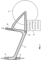
- Figure 1 schematically shows the frame 10 of a ladies' bicycle.
- the rear wheel 12, which is later arranged in the rear part of the frame, is shown schematically.
- Figure 1 The thermoplastic melt has just been injected into the closed mold (not shown in detail here).
- slides or cores 14, 16, and 18 have been inserted into the mold in the direction of the arrows, preventing the injected plastic melt from penetrating this area.
- Slides 14 and 16 form cavities for the steering head bearing
- slide 18 forms a cavity for accommodating the seat tube to be attached later
- an inserted slide 20 perpendicular to the plane of the drawing, forms the cavity in which the bottom bracket will later be located.
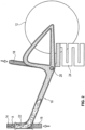
- FIG. 2 A fluid 22 is now injected in the direction of arrow A through an injector (not shown here in detail), which displaces the so-called plastic core from the interior of the component.
- an injector not shown here in detail
- Figure 2 Here, a portion of the core has already been displaced.
- the excess plastic material is pressed into a secondary cavity 24.
- the secondary or overflow cavity 24 can be opened and closed hydraulically, pneumatically, and/or electrically via a slide valve.
- the cavity of the closed injection mold forms the geometry of the bicycle frame in a manner not shown in detail.
- the mold not shown here, is equipped with at least one injector for introducing the fluid 22, which can consist of gas, water, or a mixture of gases, or of water with gas or gases.
- the fluid for displacing the plastic core can be injected using volume flow control or pressure/time control via a preset profile. Due to the tubular cross-section, the cooling phase of the hot plastic melt relates only to the remaining wall thickness. This means that a huge reduction in cooling time is achieved compared to the cooling time of a solid frame. The faster cooling time accordingly also shortens the overall cycle time, and the components can therefore be manufactured extremely cost-efficiently.
- the internal cavity reduces the mass of the entire bicycle frame, which not only brings weight but also economic advantages.
- a closed tubular cross-section generally also creates greater rigidity than a solid material frame.
- the sequence of steps is advantageously as follows: 1. Closing the injection mold; 2. Closing force build-up; 3. Injection of the thermoplastic melt; 4. Optionally only a short holding time of approx. two seconds; 5. Opening at least one injector in the tool and starting fluid injection; 6. Displacement of the plastic core from the component cavity by means of the fluid; 7. Maintaining fluid pressure inside the component for a short time (effect like a holding pressure); 8. Optional flushing process inside the component using the same fluid or a different fluid to achieve a better cooling effect; 9. Blowing out the fluid (or sucking it out using a vacuum); 10. Opening the tool and 11. Ejecting the component.
- step 9 isn't mandatory.
- gas is used as the injected fluid, it can also remain in the component.
- the fluid used can be water or gas. However, it can also consist of both media, as, for example, an air bubble is often pushed ahead of the water, or nitrogen is used first to create the cavity and then CO2 is used to cool the component.
- polyamide or a polyolefin reinforced with glass fibers and/or carbon fibers and/or natural fibers is preferably used as the thermoplastic material.
- tapes or organic sheets i.e. glass, natural or carbon fiber fabrics
- the tapes can be placed and held in the tool by a special device. Due to the targeted fiber orientation of the tapes/organic sheet springs or tapes, the frame gets more stiffness in the critical areas, such as the pedal or steering head bearings.
- the tapes can be particularly advantageously Before being inserted into the tool, the tape must be preheated to a specific temperature, whereby this specific temperature must be selected depending on the matrix material of the tape.
- the required components such as pedal and/or steering head bearings, threaded sleeves for water bottle holders, the battery holder when designed as an electric bicycle, or, for example, the holder for a conventional motor when the invention is used in motor-driven two-wheelers such as motorcycles, can be inserted directly into the injection mold and overmolded. This can significantly simplify the production process, since this process step allows the bicycle frame to be removed from the injection mold immediately with the required components.
- the frame can be provided with a printed design using foils. These are inserted into the tool and back-injected. This is also known as "in-mold labeling" or "in-mold decoration.”
- functionalities can also be achieved using functionalized foils. These functionalized foils are also inserted into the tool and back-injected with the plastic material.
- the functionalized foils can, for example, be printed circuit boards or capacitive sensors with, if necessary, an attached microcontroller. They can also contain transponder properties.
- the foil could be functionalized with a GPS signal, which could then be used for theft protection.
- a bicycle frame 10 as it is shown in the first embodiment using the Figures 1 to 5 As explained, it can be manufactured from a single polymer or a mixture of several. Polyamides or polyolefins are generally particularly recommended for the frame. TPE or TPU can also be injected into the mold as additional components. These do not necessarily require a cavity, but are often used to overmold or encase the first component.
- FIG. 6 to 10 A further embodiment of the invention is shown schematically.
- the bicycle frame 10 thus has a Figures 1 to 5 different shape, as is typical for a men's bicycle. Essentially, the same components are designated with the same reference numerals.
- the sequence of steps in the manufacturing process, as described in the Figures 6 to 10 is essentially the same as that according to the Figures 1 to 5 of the first embodiment.
- a center strut 26 made of aluminum or another material is inserted into the injection molding tool, so that it bonds with the thermoplastic during the injection molding process.
- This center strut 26 also has the receiving opening for the seat post to be inserted later and can also be filled with another material, preferably polyurethane, for process-related or other reasons.
- the fluid 22 is injected in the direction of arrow B to displace the plastic core.
- Figures 6 to 10 the respective progress of the displacement of the soul is shown, whereby here too the plastic soul is displaced into a secondary cavity 24.
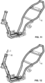
- FIGs 11 to 15 The manufacture of a frame for a scooter (motor scooter), which is not covered by the invention, is also shown schematically. This is a motor-driven two-wheeler. The somewhat more stable and complex frame of the scooter 10 results from the illustration according to the Figure 11 As with the bicycle frame, only the plastic material is shown here and not the closed injection mold.
- the frame made of thermoplastic matrix material, can be recycled at any time and is therefore reusable.
- a tube is inserted into the mold.
- the tube serves as the core and can be inflated using the fluid pressure in the cavity.
- the fluid in the tube is pressurized. This pressure leads to better part quality during the process, although the pressure can vary over time (pressure/time profile).
- the inflated tube forms the cavity.
- a bicycle frame 10 as it is shown in the first embodiment using the Figures 1 to 5 As explained, it can be manufactured from a single polymer or a mixture of several. Polyamides or polyolefins are generally particularly recommended for the frame. TPE or TPU can also be injected into the mold as additional components. These do not necessarily require a cavity, but are often used to overmold or encase the first component.
- a further embodiment of the invention is shown schematically.
- the bicycle frame 10 thus has a the first embodiment according to the Figures 1 to 5 different shape, as is typical for a men's bicycle.
- the same components are designated with the same reference numerals.
- the sequence of steps in the manufacturing process, as described in the Figures 6 to 10 is essentially the same as that according to the Figures 1 to 5 of the first embodiment.
- a center strut 26 made of aluminum or another material is inserted into the injection molding tool, so that it bonds with the thermoplastic during the injection molding process.
- This center strut 26 also has the receiving opening for the seat post to be inserted later and can also be filled with another material, preferably polyurethane, for process-related or other reasons.
- the fluid 22 is injected in the direction of arrow B to displace the plastic core.
- Figures 6 to 10 the respective progress of the displacement of the soul is shown, whereby here too the plastic soul is displaced into a secondary cavity 24.
- the method according to the invention can be used to manufacture more than just bicycle frames.
- a frame for a scooter is shown schematically. This is a motor-driven two-wheeler.
- the somewhat more stable and complex frame of the scooter 10 results from the illustration according to the Figure 11 As with the bicycle frame, only the plastic material is shown here and not the closed injection mold.
- the fluid is injected in the direction of arrow C.
- the secondary cavity which is located behind the frame or which accommodates the injection molding tool with a hot, semi-hot, or cold runner (for the mass compression molding process) and the displaced plastic material.
- This more complex example shows that the simple and fast manufacturing process for the two-wheeler frame can also be used for motor-driven two-wheelers with a more complex frame structure.
Landscapes
- Engineering & Computer Science (AREA)
- Mechanical Engineering (AREA)
- Manufacturing & Machinery (AREA)
- Injection Moulding Of Plastics Or The Like (AREA)
- Moulds For Moulding Plastics Or The Like (AREA)
Description
- Die Erfindung betrifft ein Verfahren zur Herstellung eines im Inneren mindestens einen Hohlraum aufweisenden Kunststoffrahmens für ein Zweirad, wie beschrieben im Oberbegriff des Anspruchs 1.
- Es ist bereits bekannt, Fahrradrahmen aus Kunststoff herzustellen. Hierzu wird üblicherweise ein Harzinjektionsverfahren, welches unter der Bezeichnung "Resin Transfer Moulding" (RTM) bekannt ist, eingesetzt. Bei diesem Verfahren werden Glas- und/oder Kohlefasergewebe in ein formgebendes Werkzeug eingelegt. Bei geschlossenem Werkzeug wird das Gewebe mit einem duroplastischen Matrixmaterial, wie einem Epoxyharz oder Polyurethan welches in das Werkzeug injiziert wird, getränkt. Die duroplastischen Matrixmaterialien bestehen meist aus zwei Grundsubstanzen, welche vor dem Einbringen in das Werkzeug gut miteinander vermischt werden müssen. Nach der Vermischung und der Injektion in das Werkzeug erfolgt eine chemische Reaktion. Nach entsprechender Umsetzung der Reaktanzen kann das Bauteil entformt werden.
- Die Glas- oder Kohlefasergewebe werden üblicherweise in einem dreidimensional verwebten Zustand in das Werkzeug eingelegt. Im Inneren des Gewebes wird meist ein aufblasbarer Schlauch eingelegt, sodass nach der Harzinjektion der Schlauch im Bauteilinneren mit einem Fluid aufgeblasen werden kann, sodass hierdurch der gewünschte Hohlraum entsteht. Nach Beendigung der Reaktion der Reaktanden wird das unter Druck eingebrachte Fluid abgelassen. Das ausgehärtete Bauteil kann dann entnommen werden.
- Fahrradrahmen, die aus duroplastischen Matrixmaterial bestehen, haben den großen Nachteil, dass sie aufgrund des gewählten Materials nicht sinnvoll recycelt werden können. Abgesehen von einer thermischen Verwertung durch Verbrennen, gibt es keine vernünftige Wiederverwertung für die entsprechend hergestellten Bauteile.
- Ein Fahrradrahmen weist eine komplexe Geometrie auf, die eine Herstellung im Rahmen eines Spritzgussverfahrens kompliziert machen. Insbesondere umfasst der Rahmen mehrere längere und innen hohle Rohre, die im Winkel zueinander angeordnet sind und unterschiedliche Querschnitte haben. Ferner sind diverse Anbauteile am Rahmen unterzubringen. Die Druckschrift
CN 103 552 220 A offenbart die grundlegende Idee, die Hohlräume in den Rohren durch Verdrängung des noch flüssigen Kunststoffs im Kern der stangenartigen Kunststoffgebilde in der Kavität zu schaffen. - Aufgabe der vorliegenden Erfindung ist es, ein Verfahren zur Herstellung eines Kunststoffrahmens für ein Zweirad an die Hand zu geben, bei dem ein Kunststoff einsetzbar ist, der ein sinnvolles Recycling des Zweiradrahmens ermöglicht.
- Erfindungsgemäß ist zur Lösung dieser Aufgabe ein Verfahren zur Herstellung eines im Inneren mindestens einen Hohlraum aufweisenden Kunststoffrahmens für ein Zweirad mittels Kunststoffspritzguss mit den Schritten entsprechend dem Anspruch 1 an die Hand gegeben.
- Das erfindungsgemäße Verfahren umfasst zumindest folgende Schritte:
- Einspritzen einer thermoplastischen Kunststoffschmelze in ein geschlossenes Spritzgusswerkzeug;
- Injizieren eines Fluids zur Verdrängung der plastischen Seele aus der Bauteilkavität und
- zumindest kurzes Aufrechterhalten des Fluiddruckes im Bauteilinneren.
- Bei dem erfindungsgemäßen Verfahren bildet die Kavität des geschlossenen Spitzgusswerkzeugs die Geometrie eines Zweiradrahmens, beispielsweise eines Fahrradrahmens, wobei das Werkzeug mit mindestens einem Injektor für die Einbringung eines Fluids ausgerüstet ist. Das Fluid ist in der Lage, die plastische Seele zu verdrängen und so einen rohrförmigen Querschnitt zu erzielen. Das Fluid wird volumenstrom- oder druck-/zeitgeregelt über ein voreingestelltes Profil injiziert. Durch den rohrförmigen Querschnitt kann die Abkühlphase der heißen Kunststoffschmelze aufgrund der vergleichsweise dünnen verbleibenden Restwandstärke erheblich verkürzt werden. Das bedeutet, dass nur eine vergleichsweise kurze Kühlzeit benötigt wird. Insgesamt ist mit einer sehr deutlichen Kühlzeitreduktion gegenüber einem Rahmen aus vollem Material zu rechnen. Aufgrund der schnelleren Kühlzeit kann die gesamte Zeit für die Herstellung eines Zweiradrahmens deutlich verkürzt werden. Somit lassen sich diese Bauteile noch kosteneffizienter fertigen. Darüber hinaus wird durch den bauteilinneren Hohlraum die Masse des gesamten Zweiradrahmens deutlich reduziert, was nicht nur einen Gewichtsvorteil sondern insbesondere einen ökonomischen Vorteil mit sich bringt. Bei einem geschlossenen rohrförmigen Querschnitt kann man auch von höherer Steifigkeit ausgehen. Wenn hier von einem rohrförmigen Querschnitt die Rede ist, kann dieser selbstverständlich kreisrund, oval, mehreckig und in jeder anderen beliebigen Form ausgebildet sein.
- Vorteilhaft wird das Fluid nach zumindest kurzem Aufrechterhalten des Fluiddrucks ausgeblasen und/oder abgesaugt.
- Demnach kann das Fluid die plastische Seele beispielsweise in eine in dem Spritzgusswerkzeug vorgesehene Nebenkavität drücken.
- Gemäß einer alternativen Ausgestaltung der Erfindung kann das Fluid die plastische Seele über ein Masserückdrückverfahren durch den im Spritzgusswerkzeug befindlichen Heizkanal oder Teilheißkanal oder Kaltkanal der Kunststoffspritzgussmaschine in den Schneckenvorraum drücken.
- Nach wieder einer vorteilhaften Ausgestaltung des erfindungsgemäßen Verfahrens kann das Spritzgusswerkzeug mit der vorteilhaft thermoplastischen Kunststoffschmelze nur teilgefüllt werden, wobei die plastische Seele dadurch verdrängt wird, dass sie vorzugsweise thermoplastische Kunststoffschmelze derart aufgeblasen wird, dass sie sich unter Bildung eines Hohlraums an die Wandung des Spritzgusswerkzeugs anlegt. Diese als Aufblasverfahren bekannte Verfahrensvariante ermöglicht einen sehr sparsamen Einsatz des für die Bildung des Rahmens zur Verfügung zu stellenden Kunststoffs.
- Erfindungsgemäß ist vorgesehen, dass im Bereich wenigstens eines in den Kunststoffrahmen zu integrierenden Teils, wie beispielsweise eines Motors oder eines Ackumulators, ein entsprechend geformter Kern während des Spritzgussvorgangs eingesetzt wird, sodass dieser Bereich nach der Bauteilentformung hohl ist. In diese so gebildete Ausnehmung kann dann bei der Endmontage das jeweilige Bauteil, also beispielsweise der Motor oder der Akkumulator eingesetzt werden.
- Gemäß einer weiteren Ausbildung der Erfindung kann vor dem Einspritzen der Kunststoffschmelze eine Design- und/oder Funktionsfolie und/oder ein Tape aus Kohle- oder Glasfasergewebe in das Werkzeug eingelegt und mit der Kunststoffschmelze hinterspritzt werden. Diese Folie kann selbstverständlich auch als Kombinationsfolie eingesetzt werden, die ein bestimmtes gewünschtes Design und auch eine bestimmte Funktionalität aufweist. Eine derartige Funktionalität könnte beispielsweise eine kapazitive Sensorik sein, über die das Zweiradlicht ein oder ausgeschaltet wird.
- Wiederum eine andere vorteilhafte Ausgestaltung der Erfindung sieht vor, dass Teile des Zweiradrahmens, wie beispielsweise die Mittelstrebe als fertiges Teil aus Kunststoff, Aluminium oder einem anderen Material in das Spritzgusswerkzeug eingelegt und mit dem vorteilhaft thermoplastischen Kunststoff während des Spritzvorganges verbunden werden.
- Obwohl das Fluid in erster Linie zur Bildung des Hohlraums im Kunststoffrahmen dient, kann es dadurch mit einem Zweitnutzen ausgestattet werden, dass es nach der Bildung des Hohlraums in einer Zirkulationsströmung geführt wird, sodass es nunmehr zur Kühlung des unmittelbar nach dem Spritzprozess noch sehr heiße Kunststoffmaterials dient.
- Vorteilhaft kann in dem erfindungsgemäßen Verfahren ein Kunststoff eingesetzt werden, der aus der folgenden Gruppe ausgewählt ist:
Polyamid, vorzugsweise Polyamid 12, Polyamid 6 oder Polyamid 6.6, Polypropylen, Polyethylen, Polyethersulfon, Polyetherimid, Polyetherketon, Polyphenylensulfid, Polyvinylchlorid, Polyester, Acrylnitril-Butadien-Styrol (ABS), Polycarbonat/Acrylnitril-Butadien-Styrol (ABC/PC), Polycarbonat (PC) und besonders bevorzugt Polybutylenterephtalat oder Polyterephtalatethylen. - Auch diese Materialien können einzeln oder in Kombination ausgewählt und hier eingesetzt werden. Die ausgewählten Kunststoffe können darüber hinaus noch über Kurz- und/oder Langfasern aus Glas-, Carbon- und/oder Naturfasern verstärkt werden.
- Alternativ kann der Kunststoff auch als Caprolactam mit einem zugehörigen Aktivator in dem Spritzgusswerkzeug eingespritzt werden und im beheizten Werkzeug polymerisiert werden.
- Das injizierte Fluid kann vorteilhaft Wasser und/oder ein Gas sein. Dieses Fluid wird über mindestens einen im Werkzeug angeordneten Injektor eingebracht.
- Weitere Merkmale, Einzelheiten und Vorteile werden anhand von in der Zeichnung dargestellten Ausführungsbeispielen, die Teilweise in den Figuren dargestellt sind, näher erläutert.
- Es zeigen:
- Figuren 1 bis 5:
- den Kunststoffrahmen eines Damenfahrrades nach einem ersten Ausführungsbeispiel der Erfindung in unterschiedlichen schematisch dargestellten Verfahrensstadien;
- Figuren 6 bis 10:
- einen Kunststoffrahmen eines Herrenfahrrades gemäß einer zweiten Ausführungsform der Erfindung in unterschiedlichen schematisch dargestellten Verfahrensstadien und
- Figuren 11 bis 15:
- den Kunststoffrahmen eines Scooters gemäß einem nicht von der Erfindung umfassten Verfahren in unterschiedlichen schematisch dargestellten Verfahrensstadien.
- Anhand des ersten Ausführungsbeispiels der vorliegenden Erfindung gemäß den Figuren 1 bis 5 kann der grundsätzliche Verfahrensablauf des erfindungsgemäßen Verfahrens zur Herstellung eines Zweiradkunststoffrahmens erläutert werden.
- So ist in
Figur 1 schematisch der Rahmen 10 eines Damenfahrrades gezeigt. Schematisch ist das im hinteren Teil des Rahmens später angeordnete Hinterrad 12 dargestellt. In derFigur 1 ist die thermoplastische Kunststoffschmelze gerade in das hier sonst nicht näher dargestellte geschlossene formgebende Werkzeug eingespritzt worden. Gleichzeitig sind in das Werkzeug Schieber bzw. Kerne 14, 16 und 18 in das formgebende Werkzeug in der jeweiligen Pfeilrichtung eingeschoben worden, sodass sie ein Eindringen der eingespritzten Kunststoffschmelze in diesen Bereich verhindern. Die Schieber 14 und 16 bilden hier Kavitäten für das Lenkkopflager, der Schieber 18 eine Kavität zur Aufnahme des später anzubringenden Sattelrohrs und ein senkrecht zur Zeichenebene stehender eingeschobener Schieber 20 bildet den Hohlraum, in dem später das Tretlager angeordnet wird. EntsprechendFigur 2 wird nun in Pfeilrichtung des Pfeils A ein Fluid 22 durch einen hier nicht näher dargestellten Injektor eingepresst, der die sogenannte plastische Seele aus dem Bauteilinneren verdrängt. In derFigur 2 ist hier ein Teil der Seele bereits verdrängt worden. Das überschüssige Kunststoffmaterial wird bei dieser Ausführungsform in eine Nebenkavität 24 gedrückt. Die Neben- oder Überlaufkavität 24 kann dabei über einen Schieber Hydraulisch, pneumatisch und/oder elektrisch geöffnet und geschlossen werden. - In
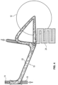
Figur 3 ist bereits ein größerer Teil des Rahmens 10 entsprechend mit dem injizierten Fluid gefüllt. InFigur 4 sind die Fluidinjektion und die Verdrängung der plastischen Seele aus dem Rahmenbereich soweit abgeschlossen. Gemäß der Darstellung nachFigur 5 werden nun die Schieber 14, 16, 18 und 20 nach entsprechendem Abkühlen des Kunststoffmaterials in entsprechende Pfeilrichtung herausgezogen und die Nebenkavität 22 wird abgetrennt. - Bei dem vorgenannten Ausführungsbeispiel bildet in nicht näher dargestellter Weise die Kavität des geschlossenen Spritzgußwerkzeuges die Geometrie des Fahrradrahmens. Das hier nicht dargestellte Werkzeug wird mit mindestens einem Injektor für die Einbringung des Fluids 22, welches aus Gas, Wasser oder einem Gemisch von Gasen oder von Wasser mit Gas oder Gasen bestehen kann, ausgerüstet. Das Fluid zur Verdrängung der plastischen Seele kann volumenstromgeregelt oder aber auch Druck/Zeit-geregelt über ein voreingestelltes Profil injiziert werden. Durch den rohrförmigen Querschnitt bezieht sich die Abkühlphase der heißen Kunststoffschmelze lediglich auf die verbleibende Restwandstärke. Das bedeutet, dass gegenüber der Abkühlzeit eines vollen Rahmens eine enorme Kühlzeitreduktion erzielt wird. Die schnellere Kühlzeit verkürzt dementsprechend auch die gesamte Zykluszeit und die Bauteile lassen sich daher überaus kosteneffizient fertigen. Durch den bauteilinneren Hohlraum wird die Masse des gesamten Zweiradrahmens reduziert, was nicht nur einem Gewichts- sondern auch einen ökonomischen Vorteil mit sich bringt. Mit einem geschlossenen rohrförmigen Querschnitt wird grundsätzlich auch eine höhere Steifigkeit erzeugt, als bei einem Vollmaterialrahmen.
- Im Folgenden wird der vollständige Verfahrensablauf zur Herstellung des Zweiradrahmens in Form der vorzunehmenden Verfahrensschritte wiedergegeben. Die Schrittfolge läuft vorteilhaft wie folgt ab:
1. Schließen des Spritzgußwerkzeuges; 2. Schließkraftaufbau; 3. Einspritzen der thermoplastischen Kunststoffschmelze; 4. Wahlweise nur eine geringe Nachdruckzeit von ca. zwei Sekunden; 5. Öffnen von mindestens einem Injektor im Werkzeug und Beginn mit der Fluidinjektion; 6. Verdrängung der plastischen Seele mittels des Fluids aus der Bauteilkavität; 7. Aufrechterhaltung des Fluiddrucks für eine kurze Zeit im Bauteilinneren (Wirkung wie ein Nachdruck); 8. Wahlweise Spülvorgang im Bauteilinneren mittels des gleichen Fluids oder einem anderen Fluid, um eine bessere Kühlwirkung zu erzielen; 9. Ausblasen des Fluids (oder Absaugen mittels Vakuum); 10. Öffnen des Werkzeugs und 11. Auswerfen des Bauteils. - Bei dieser Schrifftfolge ist zu beachten, dass der Schritt 9 nicht zwangsweise durchgeführt wird. Bei Verwendung von Gas als injiziertes Fluid kann dieses auch im Bauteil verbleibenDas verwendete Fluid kann aus Wasser oder Gas bestehen. Es kann aber auch aus beiden Medien bestehen, da beispielsweise häufig eine Luftblase vor dem Wasser vorangeschoben wird, oder wobei zunächst Stickstoff zur Hohlraumbildung und anschließend CO2 zur Bauteilkühlung herangezogen wird.
- Im dargestellten Ausführungsbeispiel wird bevorzugt als thermoplastisches Kunststoffmaterial Polyamid oder ein Polyolefin, welches über Glasfasern und/oder Kohlefasern und/oder Naturfasern verstärkt ist, verwendet.
- Um den Rahmen 10 so steif wie möglich zu gestalten, können so genannte Tapes oder Organobleche, d.h. Glas-, Natur- oder Kohlefasergewebe in bestimmten Bereichen in das Werkzeug eingelegt werden. Diese werden kann mit der Kunststoffschmelze hinterspritzt. Die Tapes können von einer besonderen Vorrichtung im Werkzeug platziert und gehalten werden. Durch die zielorientierte Faserausrichtung der Tapes/ Organoblecheder Tapes bekommt der Rahmen in den kritischen Bereichen, wie beispielsweise im Bereich des Tret- oder Lenkkopflagers, mehr Steifigkeit. Um eine bestmögliche Verbindung zwischen den Tapes und der thermoplastischen Kunststoffschmelze zu erreichen, können die Tapes besonders vorteilhaft vor dem Einlegen in das Werkzeug auf eine bestimmte Temperatur vorgewärmt werden, wobei diese bestimmte Temperatur abhängig vom Matrixmaterial des Tapes zu wählen ist.
- Um nach dem Spritzguß einen späteren zusätzlichen Aufwand für den Ein- und Anbau von zusätzlich benötigen Komponenten für den fertigen Fahrradrahmen zu vermeiden, können die benötigten Komponenten, wie beispielsweise Tret- und/oder Lenkkopflager, Gewindehülsen für Trinkflaschenhalterungen, die Haltung für Akkus bei Ausgestaltung als Elektrofahrrad oder beispielsweise die Halterung für einen konventionellen Motor im Falle der Verwendung der Erfindung im Rahmen von motorbetriebenen Zweirädern, wie Motorrädern, gleich in das Spritzgußwerkzeug eingelegt und umspritzt werden. So kann sich im Produktionsprozess der Verfahrensablauf wesentlich vereinfachen, da mit diesem Verfahrensschritt der Fahrradrahmen gleich mit den benötigten Komponenten aus dem Spritzgußwerkzeug entnommen werden kann.
- Zur Erzeugung eines schönen und individuellen Designs kann der Rahmen über Folien mit einem bedruckten Design versehen werden. Diese werden in das Werkzeug eingelegt und hinterspritzt. Dies wird auch als "Inmold Labelling" oder "Inmold Decoration" bezeichnet. Anstelle der reinen Designfolien können auch Funktionalitäten über funktionalisierte Folien erreicht werden. Diese mit der Funktionalität versehenen Folien werden ebenfalls in das Werkzeug eingelegt und mit dem Kunststoffmaterial hinterspritzt. Die funktionalisierten Folien können beispielsweise bedruckte Leiterbahnen bzw. eine kapazitive Sensorik mit ggf. einem aufgebrachten Microcontroller sein. Sie können aber auch Transpondereigenschaften beinhalten. Des Weiteren könnte man Folie mit einem GPS-Signal funktionalisieren, wobei dieses dann zur Diebstahlsicherung herangezogen werden könnte.
- Durch die positive Eigenschaft, dass der Rahmen aus Kunststoff besteht und daher nicht leitend ist, kann man über die ein- und/oder aufgebrachte Funktionalität störungsfrei Signale, Daten und/oder Energie übermitteln bzw. übertragen. Eine zusätzliche Verkabelung um die hergestellte Energie von einer energieerzeugenden Einheit, wie beispielsweise einem Dynamo zum Verbraucher, beispielsweise der Fahrradleuchte zu leiten, könnte auch mittels einer entsprechend funktionalisierten Folie substituiert werden.
- Ein Fahrradrahmen 10, wie er beispielsweise in dem ersten Ausführungsbeispiel unter Hinzuziehung der
Figuren 1 bis 5 erläutert wurde, kann aus einem einzigen, aber auch aus einer Mischung mehrerer Polymere hergestellt werden. Für den Rahmen sind grundsätzlich Polyamide oder Polyolifine besonders empfehlenswert. Als weitere Komponenten können aber auch TPE oder TPU in das Werkzeug eingespritzt werden. Diese sind nicht zwangsläufig mit einem Hohlraum zu versehen, sondern dienen oftmals zur Überspritzung bzw. als Ummantelung der ersten Komponente. - Anhand der
Figuren 6 bis 10 ist eine weitere Ausführungsform der Erfindung schematisch dargestellt. Hier ist das Verfahren zur Herstellung eines Herrenfahrrades gezeigt. Der Fahrradrahmen 10 hat also eine gegenüber dem Fahrradrahmen gemäß dem ersten Ausführungsbeispiel nach denFiguren 1 bis 5 unterschiedliche Formgebung, wie sie für ein Herrenfahrrad charakteristisch ist. Im Wesentlichen sind hier die gleichen Bauteile ebenfalls mit gleichem Bezugszeichen bezeichnet. Die Schrittabfolge des Herstellungsverfahrens, wie sie in denFiguren 6 bis 10 dargestellt ist, entspricht im Wesentlichen auch derjenigen gemäß derFiguren 1 bis 5 der ersten Ausführungsbeispiels. Allerdings ist in diesem Beispiel eine Mittelstrebe 26 aus Aluminium oder aus einem anderen Material in das Spritzgußwerkzeug eingelegt, sodass es sich während des Spritzgußvorganges mit dem thermoplastischen Kunststoff verbindet. Diese Mittelstrebe 26 weist auch die Aufnahmeöffnung für die später einzusetzende Sattelstütze auf und kann auch aus prozesstechnischen oder anderen Gründen mit einem anderen Material, vorzugsweise Polyurethan, gefüllt sein. - Das Fluid 22 wird im hier dargestellten Ausführungsbeispiel in Pfeilrichtung des Pfeils B zum Verdrängen der plastischen Seele injiziert. In den
Figuren 6 bis 10 ist der jeweilige Fortschritt der Verdrängung der Seele dargestellt, wobei auch hier die plastische Seele in eine Nebenkavität 24 verdrängt wird. - Zum Vergleich ist in
Figuren 11 bis 15 noch schematisch die nicht von der Erfindung umfasste Herstellung eines Rahmens für einen Scooter (Motorroller) dargestellt. Hierbei handelt es sich um ein motorbetriebenes Zweirad. Der etwas stabilere und komplexere Rahmen des Scooters 10 ergibt sich aus der Darstellung gemäß derFigur 11 . Wie auch zuvor bei dem Fahrradrahmen ist hier lediglich das Kunststoffmaterial und nicht das geschlossene Spritzgußwerkzeug gezeigt. - Entsprechend der
Figur 12 wird in Pfeilrichtung C das Fluid injiziert. Dieses verdrängt die plastische Seele zunehmend, wobei die jeweiligen Fortschritte der Verdrängung der Seele in denFiguren 13 bis 15 gezeigt sind. Nicht näher dargestellt ist in diesem Ausführungsbeispiel die Nebenkavität, die hinter dem Rahmen anschließt oder auch das Spritzgusswerkzeug mit einem Heiß-, Teiheiß- oder Kaltkanal (dür das Masserpckdrückverfahren) und das verdrängte Kunststoffmaterial aufnimmt. Anhand dieses komplexeren Beispiels kann gezeigt werden, dass das einfache und schnelle Herstellverfahren für den Zweiradrahmen auch bei Motor betriebenen Zweirädern mit komplexerem Rahmenaufbau verwendet werden kann.
Werkzeug derart eingebracht wird, dass das im Werkzeug eingelegte Gewebe durchflutet wird. - Erhöhung von Temperatur und Druck im Werkzeuginneren und dadurch Polymerisierung der eingebrachten Kunststoffmasse.
- Entnahme des Zweiradrahmens nach abgeschlossener Polymerisation aus dem Werkzeug.
- Der aus dem thermoplastischen Matrixmaterial bestehende Rahmen ist jederzeit wieder recyclebar und dadurch wiederverwertbar.
- Bei dieser Verfahrensführung sollte im Rahmeninneren das injizierte Fluid nicht mit der Kunststoffschmelze in Berührung kommen. Daher wird bei der Insitu-Polymerisation ein Schlauch in das Werkzeug eingelegt. Der Schlauch dient hierbei als Seele und kann mittels des Fluiddrucks in der Kavität aufgeblasen werden. Während der Polymerisation wird das Fluid im Schlauch mit Druck beaufschlagt. Dieser Druck führt im Verfahren zu einer besseren Bauteilequalität, wobei der Druck über die Zeit variieren kann (Druck/Zeit-Profil). Der aufgeblasene Schlauch bildet den Hohlraum.
- Ein Fahrradrahmen 10, wie er beispielsweise in dem ersten Ausführungsbeispiel unter Hinzuziehung der
Figuren 1 bis 5 erläutert wurde, kann aus einem einzigen, aber auch aus einer Mischung mehrerer Polymere hergestellt werden. Für den Rahmen sind grundsätzlich Polyamide oder Polyolifine besonders empfehlenswert. Als weitere Komponenten können aber auch TPE oder TPU in das Werkzeug eingespritzt werden. Diese sind nicht zwangsläufig mit einem Hohlraum zu versehen, sondern dienen oftmals zur Überspritzung bzw. als Ummantelung der ersten Komponente. - Anhand der
Figuren 6 bis 10 ist eine weitere Ausführungsform der Erfindung schematisch dargestellt. Hier ist das Verfahren zur Herstellung eines Herrenfahrrades gezeigt. Der Fahrradrahmen 10 hat also eine gegenüber dem Fahrradrahmen gemäß dem ersten Ausführungsbeispiel nach denFiguren 1 bis 5 unterschiedliche Formgebung, wie sie für ein Herrenfahrrad charakteristisch ist. Im Wesentlichen sind hier die gleichen Bauteile ebenfalls mit gleichem Bezugszeichen bezeichnet. Die Schrittabfolge des Herstellungsverfahrens, wie sie in denFiguren 6 bis 10 dargestellt ist, entspricht im Wesentlichen auch derjenigen gemäß derFiguren 1 bis 5 der ersten Ausführungsbeispiels. Allerdings ist in diesem Beispiel eine Mittelstrebe 26 aus Aluminium oder aus einem anderen Material in das Spritzgußwerkzeug eingelegt, sodass es sich während des Spritzgußvorganges mit dem thermoplastischen Kunststoff verbindet. Diese Mittelstrebe 26 weist auch die Aufnahmeöffnung für die später einzusetzende Sattelstütze auf und kann auch aus prozesstechnischen oder anderen Gründen mit einem anderen Material, vorzugsweise Polyurethan, gefüllt sein. - Das Fluid 22 wird im hier dargestellten Ausführungsbeispiel in Pfeilrichtung des Pfeils B zum Verdrängen der plastischen Seele injiziert. In den
Figuren 6 bis 10 ist der jeweilige Fortschritt der Verdrängung der Seele dargestellt, wobei auch hier die plastische Seele in eine Nebenkavität 24 verdrängt wird. - Mit dem erfindungsgemäßen Verfahren lassen sich aber nicht nur Fahrradrahmen herstellen. Anhand des dritten Ausführungsbeispiels gemäß den
Figuren 11 bis 15 ist schematisch die Herstellung eines Rahmens für einen Scooter (Motorroller) dargestellt. Hierbei handelt es sich um ein motorbetriebenes Zweirad. Der etwas stabilere und komplexere Rahmen des Scooters 10 ergibt sich aus der Darstellung gemäß derFigur 11 . Wie auch zuvor bei dem Fahrradrahmen ist hier lediglich das Kunststoffmaterial und nicht das geschlossene Spritzgußwerkzeug gezeigt. - Entsprechend der
Figur 12 wird in Pfeilrichtung C das Fluid injiziert. Dieses verdrängt die plastische Seele zunehmend, wobei die jeweiligen Fortschritte der Verdrängung der Seele in denFiguren 13 bis 15 gezeigt sind. Nicht näher dargestellt ist in diesem Ausführungsbeispiel die Nebenkavität, die hinter dem Rahmen anschließt oder auch das Spritzgusswerkzeug mit einem Heiß-, Teiheiß- oder Kaltkanal (dür das Masserpckdrückverfahren) und das verdrängte Kunststoffmaterial aufnimmt. Anhand dieses komplexeren Beispiels kann gezeigt werden, dass das einfache und schnelle Herstellverfahren für den Zweiradrahmen auch bei Motor betriebenen Zweirädern mit komplexerem Rahmenaufbau verwendet werden kann.
Claims (10)
- Verfahren zur Herstellung eines im Inneren mindestens einen Hohlraum aufweisenden Kunststoffrahmens für ein Fahrrad mittels Kunststoffspritzguss, wobei der Rahmen wenigstens ein Steuerrohr, ein Unterrohr, ein Sitzrohr, Kettenstreben und Sitzstreben aufweist, und wobei das Verfahren die folgenden Schritte umfasst:- Einspritzen einer thermoplastischen Kunststoffschmelze in ein geschlossenes Spritzgusswerkzeug;- Injizieren mindestens eines Fluids zur Verdrängung der plastischen Seele aus der Bauteilkavität und- zumindest kurzes Aufrechterhalten des Fluiddruckes im Bauteilinneren,dadurch gekennzeichnet,dass mehrere Fluide in das Spritzgusswerkzeug injiziert und deren einzelnen Fluidvolumenströme oder Druck/Zeit - Profile separat voneinander geregelt werden;dass im Bereich wenigstens eines in den Kunststoffrahmen zu integrierenden Teils, beispielsweise eines Motors oder eines Akkumulators, ein entsprechend geformter Kern während des Spritzgussvorganges eingesetzt wird, so dass dieser Bereich nach der Bauteilentformung hohl ist; unddass wenigstens ein anderes in den Kunststoffrahmen zu integrierendes Teil, beispielsweise ein Lenkkopflager oder ein Tretlager, in das Spritzgusswerkzeug eingelegt, mittels einer Vorrichtung im Spritzgusswerkzeug gehalten und mit Kunststoff umspritzt wird.
- Verfahren nach Anspruch 1, dadurch gekennzeichnet, dass das Fluid nach dem kurzen Aufrechterhalten des Fluiddruckes im Bauteilinneren ausgeblasen und/oder abgesaugt wird.
- Verfahren nach Anspruch 1 oder 2, dadurch gekennzeichnet, dass das Fluid die plastische Seele in eine im Spritzgusswerkzeug vorgesehene Nebenkavität drückt.
- Verfahren nach Anspruch 1 oder 2, dadurch gekennzeichnet, dass das Fluid die plastische Seele über ein Masserückdrückverfahren durch einen Kanal, beispielsweise einen Heißkanal, einen Teilheißkanal oder einen Kaltkanal, in den Schneckenvorraum der Spritzgußmaschine drückt.
- Verfahren nach Anspruch 1 oder 2, dadurch gekennzeichnet, dass mindestens eine formgebende Kavität des Spritzgusswerkzeugs mit der thermoplastischen Kunststoffschmelze nur teilgefüllt wird und dass die plastische Seele durch das Injizieren des Fluids verdrängt wird, so dass die thermoplastische Kunststoffschmelze derart aufgeblasen wird, dass sie sich unter Bildung eines Hohlraums an die Wandung des Spritzgusswerkzeugs anlegt und die formgebende Kavität danach vollständig gefüllt ist.
- Verfahren nach einem der vorhergehenden Ansprüche, dadurch gekennzeichnet, dass vor dem Einspritzen der Kunststoffschmelze ein oder mehrere Elemente aus der Gruppe einer Design- und/oder Funktionsfolie, eines Tapes bzw. Organoblechs aus Kohle-, Glas- oder Naturfasergewebe in das Werkzeug eingelegt und mit der Kunststoffschmelze hinterspritzt oder umspritzt werden.
- Verfahren nach einem der vorhergehenden Ansprüche, dadurch gekennzeichnet, dass wenigstens ein Teil des Fahrradrahmens, beispielsweise das Sitzrohr, als fertiges Teil aus Kunststoff, Aluminium oder einem anderen Material in das Spritzgusswerkzeug eingelegt und mit dem thermoplastischen Kunststoff während des Spritzgussvorganges verbunden wird.
- Verfahren nach einem der vorhergehenden Ansprüche, dadurch gekennzeichnet, dass das Fluid nach der Hohlraumbildung zirkuliert wird, um die Kühlung des Kunststoffes zu unterstützen.
- Verfahren nach einem der vorhergehenden Ansprüche, dadurch gekennzeichnet, dass es sich bei dem Kunststoff um ein Polyamid, vorzugsweise Polyamid 12, Polyamid 6 oder Polyamid 6.6, Polypropylen oder Polyethylen, Polyethersulfon, Polyetherimid, Polyetherketon, Polyphenylensulfid, Polyvinylchlorid, einen Polyester, Acrylnitril-Butadien-Styrol (ABS), Polycarbonat/Acrylnitril-Butadien-Styrol (ABC/PC), Polycarbonat (PC), Polybutylenterephtalat oder Polyterephtalatethylen, vorzugsweise um ein Polybutylenterephtalat oder Polyterephtalatethylen handelt.
- Verfahren nach einem der vorhergehenden Ansprüche, dadurch gekennzeichnet, dass die injizierten Fluide Wasser und/oder ein oder mehrere Gase umfassen.
Applications Claiming Priority (2)
| Application Number | Priority Date | Filing Date | Title |
|---|---|---|---|
| DE102015008561.1A DE102015008561A1 (de) | 2015-07-02 | 2015-07-02 | Verfahren zur Herstellung eines Kunststoffrahmens für ein Zweirad |
| PCT/EP2016/000536 WO2017001031A1 (de) | 2015-07-02 | 2016-03-31 | Verfahren zur herstellung eines kunststoffrahmens für ein zweirad |
Publications (3)
| Publication Number | Publication Date |
|---|---|
| EP3313720A1 EP3313720A1 (de) | 2018-05-02 |
| EP3313720C0 EP3313720C0 (de) | 2025-04-30 |
| EP3313720B1 true EP3313720B1 (de) | 2025-04-30 |
Family
ID=55650381
Family Applications (1)
| Application Number | Title | Priority Date | Filing Date |
|---|---|---|---|
| EP16713736.3A Active EP3313720B1 (de) | 2015-07-02 | 2016-03-31 | Verfahren zur herstellung eines kunststoffrahmens für ein zweirad |
Country Status (6)
| Country | Link |
|---|---|
| US (1) | US11090847B2 (de) |
| EP (1) | EP3313720B1 (de) |
| JP (1) | JP6826054B2 (de) |
| CN (1) | CN107810098B (de) |
| DE (1) | DE102015008561A1 (de) |
| WO (1) | WO2017001031A1 (de) |
Families Citing this family (29)
| Publication number | Priority date | Publication date | Assignee | Title |
|---|---|---|---|---|
| DE102017118826A1 (de) * | 2017-08-17 | 2019-02-21 | Friedrich Westphal | Verfahren zur Herstellung eines Bauteils aus einer als Hohlkörper ausgebildeten Preform aus Kunststoff |
| DE102017121939A1 (de) * | 2017-09-21 | 2019-03-21 | Webasto SE | Fahrzeugdachrahmen mit Kabelkanal und Verfahren zu dessen Herstellung |
| DE102017218720A1 (de) * | 2017-10-19 | 2019-04-25 | Volkswagen Aktiengesellschaft | Funktionalisierung von Profilen mittels thermoplastischem Injektions- oder Gussverfahren |
| FR3085662B1 (fr) * | 2018-09-09 | 2022-06-24 | Olivier Glaumot | Cadre de cycle thermoplastique realise par injection assistee par fluide |
| DE102020007270A1 (de) | 2020-11-28 | 2022-06-02 | Felix Bochmann | Fahrradrahmen aus Recycling-Kunststoff |
| DE102020133019A1 (de) | 2020-12-10 | 2022-06-15 | Plastic Innovation Gmbh | Verfahren zur Herstellung eines Zweiradrahmens |
| DE102021104718A1 (de) | 2021-02-26 | 2022-09-01 | FOND OF GmbH | Kinderlaufradrahmen und Kinderfahrradrahmen |
| CN113071063B (zh) * | 2021-04-29 | 2022-07-05 | 赣州通洲塑胶机械有限公司 | 一种硅胶鼻托注塑成型工艺 |
| DE102021123470A1 (de) | 2021-09-10 | 2023-03-16 | Fte Automotive Gmbh | Spritzgusswerkzeug und Verfahren zum Spritzgießen |
| US20230114290A1 (en) * | 2021-10-12 | 2023-04-13 | Sram, Llc | Natural fiber composite bicycle component |
| DE102022110819A1 (de) | 2022-05-03 | 2023-11-09 | Plastic Innovation Gmbh | Verfahren zur Herstellung eines Kunststofflenkers für ein Zweirad |
| DE202022102923U1 (de) | 2022-05-25 | 2023-08-26 | DutchFiets B.V. | Hauptrahmen, Vorderradgabel sowie diese umfassender Fahrradrahmen |
| JP7592667B2 (ja) * | 2022-06-13 | 2024-12-02 | 横浜ゴム株式会社 | 樹脂管の製造方法および装置 |
| US12441040B2 (en) * | 2022-06-22 | 2025-10-14 | The Trustees Of Princeton University | Bubble casting soft robotics |
| EP4306289A1 (de) * | 2022-07-11 | 2024-01-17 | Polisport Plásticos, SA | Träger für ein fahrrad und verfahren zu seiner herstellung |
| DE102022118736A1 (de) * | 2022-07-26 | 2024-02-01 | Plastic Innovation Gmbh | Verfahren zur Herstellung einer Gabel für ein Zweirad |
| EP4349701A1 (de) * | 2022-10-05 | 2024-04-10 | CIP Mobility GmbH | Komponenten eines elektrofahrrads, elektrofahrrad und herstellung eines fahrradrahmens und anderer fahrradkomponenten |
| USD1110893S1 (en) | 2022-11-10 | 2026-02-03 | igus SE & Co. KG | Bicycle |
| DE102023106152A1 (de) * | 2023-03-13 | 2024-09-19 | Pme Fluidtec Gmbh | Verfahren zur Herstellung eines Formteils mittels einer Kunststoffspritzgießmaschine, Volumensplitter zur Durchführung des Verfahrens, Spritzgießwerkzeug zur Durchführung des Verfahrens und Formteil |
| CN116533458B (zh) * | 2023-06-07 | 2025-06-10 | 浙江二三四模塑有限公司 | 电动车把立筒注塑成型模具 |
| DE102023209530A1 (de) * | 2023-09-28 | 2025-04-03 | Robert Bosch Gesellschaft mit beschränkter Haftung | Rahmenbauteil für ein Fahrzeug |
| CN121969477A (zh) * | 2023-10-20 | 2026-05-01 | 横滨橡胶株式会社 | 弯曲树脂管的制造方法及弯曲树脂管 |
| DE102023132359A1 (de) | 2023-11-21 | 2024-03-21 | Audi Aktiengesellschaft | Mehrschichtiges Spritzgussbauteil und Verfahren zur Herstellung eines solchen Bauteils |
| DE102023136358A1 (de) * | 2023-12-21 | 2025-06-26 | Igus Gmbh | Strukturbauteil für ein Fahrzeug |
| DE102024108905A1 (de) * | 2024-03-28 | 2025-10-02 | Alfred Thun GmbH | Spritzgusswerkzeug und Verfahren zur Herstellung einer Tretkurbel für ein Fahrrad |
| DE102024111080A1 (de) * | 2024-04-19 | 2025-10-23 | Igus Gmbh | Verfahren zur Herstellung eines Strukturbauteils für ein Fahrrad Verfahren zur Herstellung eines Fahrradrahmens sowie Fahrradrahmen |
| DE102024112157A1 (de) * | 2024-04-30 | 2025-10-30 | Igus Gmbh | Verfahren zur Herstellung eines Fahrradrahmens, Spritzgießwerkzeug sowie Fahrradrahmen |
| DE102024118231A1 (de) * | 2024-06-27 | 2025-12-31 | Igus Gmbh | Fahrradrahmen für ein gefedertes Fahrrad sowie Verfahren zu dessen Herstellung |
| DE102024118543A1 (de) | 2024-07-01 | 2026-01-08 | Dr. Ing. H.C. F. Porsche Aktiengesellschaft | Kraftfahrzeug mit Aussteifungsstruktur |
Family Cites Families (26)
| Publication number | Priority date | Publication date | Assignee | Title |
|---|---|---|---|---|
| DE3145002C2 (de) * | 1981-11-12 | 1984-03-22 | Detmar 4980 Bünde Grünfeld | Verbindung von aus Rohren hergestellten Teilen von Fahrradrahmen bzw. -gabeln sowie Verfahren zur Herstellung derselben |
| US5456481A (en) * | 1989-04-07 | 1995-10-10 | Softride, Inc. | Modular composite bicycle frame |
| JPH0720646B2 (ja) | 1990-11-30 | 1995-03-08 | アァルピィ東プラ株式会社 | 中空体の製造法 |
| US5533742A (en) * | 1991-08-06 | 1996-07-09 | Axis Bicycle Incorporated | All-terrain bicycle frame |
| JPH05104559A (ja) * | 1991-10-21 | 1993-04-27 | Sumitomo Rubber Ind Ltd | 反応射出成形装置および反応射出成形方法 |
| DE69300067T2 (de) * | 1993-07-08 | 1995-07-20 | Omegal Sa | Verfahren zum Herstellen von Autospoilern. |
| JPH07124986A (ja) * | 1993-10-29 | 1995-05-16 | Kyoraku Co Ltd | 中空成形品の製造方法 |
| JP3482027B2 (ja) * | 1995-02-27 | 2003-12-22 | 三菱エンジニアリングプラスチックス株式会社 | 中空射出成形方法およびその装置 |
| US6264878B1 (en) * | 1995-08-25 | 2001-07-24 | James S. Busby | Composite bicycle frame and method of manufacture |
| JP2002192549A (ja) * | 2000-12-27 | 2002-07-10 | Asahi Kasei Corp | 発泡射出成形品 |
| DE10114415B4 (de) * | 2001-03-23 | 2004-11-18 | Battenfeld Gmbh | Verfahren zum Spritzgießen von mindestens einen Hohlraum aufweisenden Formteilen |
| TW548173B (en) | 2001-07-10 | 2003-08-21 | Cinpres Gas Injection Ltd | Process and apparatus for injection moulding a hollow plastics article |
| JP2004216425A (ja) * | 2003-01-15 | 2004-08-05 | Taisei Plas Co Ltd | アルミニウム合金パイプの連結継手とその製造方法 |
| JP2005066823A (ja) * | 2003-04-25 | 2005-03-17 | Suzuka Fuji Xerox Co Ltd | ガス注入ピン及び中空成形用金型 |
| CA2517940A1 (en) * | 2004-09-24 | 2006-03-24 | Ems-Chemie Ag | Injection molding method for manufacturing plastic parts |
| DE102008023473A1 (de) * | 2008-05-14 | 2009-11-19 | Röchling Automotive AG & Co. KG | Kalibrator für Gießverfahren mit Projektilinjektion (PIT) |
| JP5378729B2 (ja) * | 2008-08-29 | 2013-12-25 | アァルピィ東プラ株式会社 | 樹脂成形体及びその製造方法 |
| DE102008046602A1 (de) * | 2008-09-10 | 2010-03-11 | Daimler Ag | Verfahren zur Herstellung eines Bauteils mit einem Hohlprofil |
| US8388007B2 (en) * | 2010-10-20 | 2013-03-05 | Juan Carlos Calabresse Muzzi | Robust bicycle having hollow unitary frame |
| DE102011100132B4 (de) * | 2011-04-30 | 2020-07-23 | Vereinigung zur Förderung des Instituts für Kunststoffverarbeitung in Industrie und Handwerk an der Rhein.-Westf. Technischen Hochschule Aachen e.V. | Verfahren zur Herstellung polymererHohlkörper |
| DE102012011173A1 (de) * | 2012-06-06 | 2013-12-12 | Vereinigung zur Förderung des Instituts für Kunststoffverarbeitung in Industrie und Handwerk an der Rhein.-Westf. Technischen Hochschule Aachen e.V. | Verfahren zur Herstellung von mehrkomponentigen Kompaktformteilenund von mehrkomponentigen Hohlkörpern |
| NZ611256A (en) * | 2013-05-29 | 2014-09-26 | David Barnaby Latham Richard | Height adjustable bike |
| CN203581271U (zh) * | 2013-10-17 | 2014-05-07 | 硕懋工业股份有限公司 | 滑步车结构 |
| CN103552220A (zh) * | 2013-11-07 | 2014-02-05 | 天津国丰模具有限公司 | 自行车主体构件加工机构及加工方法 |
| CN103737790B (zh) * | 2013-12-26 | 2016-03-09 | 宁波舜宇模具有限公司 | 一种气体辅助成型装置 |
| DE102020133019A1 (de) | 2020-12-10 | 2022-06-15 | Plastic Innovation Gmbh | Verfahren zur Herstellung eines Zweiradrahmens |
-
2015
- 2015-07-02 DE DE102015008561.1A patent/DE102015008561A1/de active Pending
-
2016
- 2016-03-31 EP EP16713736.3A patent/EP3313720B1/de active Active
- 2016-03-31 US US15/740,107 patent/US11090847B2/en active Active
- 2016-03-31 WO PCT/EP2016/000536 patent/WO2017001031A1/de not_active Ceased
- 2016-03-31 JP JP2017565306A patent/JP6826054B2/ja active Active
- 2016-03-31 CN CN201680037916.1A patent/CN107810098B/zh active Active
Also Published As
| Publication number | Publication date |
|---|---|
| EP3313720C0 (de) | 2025-04-30 |
| JP6826054B2 (ja) | 2021-02-03 |
| WO2017001031A1 (de) | 2017-01-05 |
| CN107810098A (zh) | 2018-03-16 |
| EP3313720A1 (de) | 2018-05-02 |
| JP2018519192A (ja) | 2018-07-19 |
| US20180186049A1 (en) | 2018-07-05 |
| DE102015008561A1 (de) | 2017-01-05 |
| US11090847B2 (en) | 2021-08-17 |
| CN107810098B (zh) | 2022-03-04 |
Similar Documents
| Publication | Publication Date | Title |
|---|---|---|
| DE102015008561A1 (de) | Verfahren zur Herstellung eines Kunststoffrahmens für ein Zweirad | |
| DE102010019625B4 (de) | Verfahren zur Herstellung einer Verbund- oder Hybridkonstruktion | |
| EP2004380B1 (de) | Verfahren und vorrichtung zur herstellung von mehrkomponentigen kunststoff-formteilen | |
| EP2012992B1 (de) | Verfahren zur herstellung eines verbundbauteils | |
| EP2089207B1 (de) | Verfahren und Vorrichtung zur Herstellung eines Verbundbauteils, insbesondere umfassend ein Spritzgussteil mit einer Polyurethan-Beschichtung | |
| EP1843887B1 (de) | Spritzgiessmaschine mit aus einer halterung entnehmbarem formeinsatzpaar | |
| DE4030964A1 (de) | Verfahren zum herstellen eines kunststofformteils | |
| EP2740579B1 (de) | Verfahren zur Herstellung eines Kunststoffbauteils | |
| EP0495219A2 (de) | Verfahren und Vorrichtung zum Herstellen laminierter Formteile | |
| EP4272923A1 (de) | Verfahren zur herstellung eines kunststofflenkers für ein zweirad | |
| DE10227636A1 (de) | Verfahren und Vorrichtung zum Herstellen mehrkomponentiger Kunststoff-Formteile | |
| DE10306780B4 (de) | Verfahren und Vorrichtung für Schaumspritzguss | |
| DE102014011135B4 (de) | Verfahren und Vorrichtung zur Herstellung eines Dekorteils | |
| EP0543085A1 (de) | Verfahren und Vorrichtung zum Herstellen laminierter Formteile | |
| DE102012014082B4 (de) | Dekorformteil und Verfahren zu dessen Herstellung | |
| WO2021074004A1 (de) | Verfahren zur herstellung eines composite bauteils mit störungsfreier oberfläche | |
| DE102007009384B4 (de) | Verfahren zum Hinterspritzen einer Folie | |
| DE4224171A1 (de) | Spritzgußteil sowie Verfahren und Spritzgießwerkzeug zum Herstellen von Spritzgußteilen | |
| EP3328607B1 (de) | Verfahren und vorrichtung zum herstellen eines kaschierten formteils | |
| WO2024022744A1 (de) | Verfahren zur herstellung einer gabel für ein zweirad | |
| DE102005037274A1 (de) | Verfahren und Vorrichtung zur Herstellung von zylindrischen Formteilen nach dem Verfahren des In-Mold-Labeling | |
| WO2023094552A1 (de) | Verfahren zur herstellung eines kombinationsbauteils und kombinationsbauteil | |
| DE102007060863B4 (de) | Verfahren zur Herstellung mehrkomponentiger Kunststoffkorken | |
| DE102024113146A1 (de) | Verfahren und Spritzgusswerkzeug zur Herstellung eines Bauteils | |
| DE102011004015A1 (de) | Vorrichtung und Verfahren zum Herstellen eines mehrteiligen Bauteils |
Legal Events
| Date | Code | Title | Description |
|---|---|---|---|
| STAA | Information on the status of an ep patent application or granted ep patent |
Free format text: STATUS: THE INTERNATIONAL PUBLICATION HAS BEEN MADE |
|
| PUAI | Public reference made under article 153(3) epc to a published international application that has entered the european phase |
Free format text: ORIGINAL CODE: 0009012 |
|
| STAA | Information on the status of an ep patent application or granted ep patent |
Free format text: STATUS: REQUEST FOR EXAMINATION WAS MADE |
|
| 17P | Request for examination filed |
Effective date: 20171201 |
|
| AK | Designated contracting states |
Kind code of ref document: A1 Designated state(s): AL AT BE BG CH CY CZ DE DK EE ES FI FR GB GR HR HU IE IS IT LI LT LU LV MC MK MT NL NO PL PT RO RS SE SI SK SM TR |
|
| AX | Request for extension of the european patent |
Extension state: BA ME |
|
| DAV | Request for validation of the european patent (deleted) | ||
| DAX | Request for extension of the european patent (deleted) | ||
| STAA | Information on the status of an ep patent application or granted ep patent |
Free format text: STATUS: EXAMINATION IS IN PROGRESS |
|
| 17Q | First examination report despatched |
Effective date: 20201013 |
|
| TPAC | Observations filed by third parties |
Free format text: ORIGINAL CODE: EPIDOSNTIPA |
|
| GRAP | Despatch of communication of intention to grant a patent |
Free format text: ORIGINAL CODE: EPIDOSNIGR1 |
|
| STAA | Information on the status of an ep patent application or granted ep patent |
Free format text: STATUS: GRANT OF PATENT IS INTENDED |
|
| INTG | Intention to grant announced |
Effective date: 20241213 |
|
| GRAS | Grant fee paid |
Free format text: ORIGINAL CODE: EPIDOSNIGR3 |
|
| GRAA | (expected) grant |
Free format text: ORIGINAL CODE: 0009210 |
|
| STAA | Information on the status of an ep patent application or granted ep patent |
Free format text: STATUS: THE PATENT HAS BEEN GRANTED |
|
| AK | Designated contracting states |
Kind code of ref document: B1 Designated state(s): AL AT BE BG CH CY CZ DE DK EE ES FI FR GB GR HR HU IE IS IT LI LT LU LV MC MK MT NL NO PL PT RO RS SE SI SK SM TR |
|
| REG | Reference to a national code |
Ref country code: CH Ref legal event code: EP Ref country code: GB Ref legal event code: FG4D Free format text: NOT ENGLISH |
|
| REG | Reference to a national code |
Ref country code: DE Ref legal event code: R096 Ref document number: 502016016968 Country of ref document: DE |
|
| REG | Reference to a national code |
Ref country code: IE Ref legal event code: FG4D Free format text: LANGUAGE OF EP DOCUMENT: GERMAN |
|
| U01 | Request for unitary effect filed |
Effective date: 20250430 |
|
| U07 | Unitary effect registered |
Designated state(s): AT BE BG DE DK EE FI FR IT LT LU LV MT NL PT RO SE SI Effective date: 20250508 |
|
| PG25 | Lapsed in a contracting state [announced via postgrant information from national office to epo] |
Ref country code: ES Free format text: LAPSE BECAUSE OF FAILURE TO SUBMIT A TRANSLATION OF THE DESCRIPTION OR TO PAY THE FEE WITHIN THE PRESCRIBED TIME-LIMIT Effective date: 20250430 |
|
| PG25 | Lapsed in a contracting state [announced via postgrant information from national office to epo] |
Ref country code: NO Free format text: LAPSE BECAUSE OF FAILURE TO SUBMIT A TRANSLATION OF THE DESCRIPTION OR TO PAY THE FEE WITHIN THE PRESCRIBED TIME-LIMIT Effective date: 20250730 Ref country code: GR Free format text: LAPSE BECAUSE OF FAILURE TO SUBMIT A TRANSLATION OF THE DESCRIPTION OR TO PAY THE FEE WITHIN THE PRESCRIBED TIME-LIMIT Effective date: 20250731 |
|
| PG25 | Lapsed in a contracting state [announced via postgrant information from national office to epo] |
Ref country code: PL Free format text: LAPSE BECAUSE OF FAILURE TO SUBMIT A TRANSLATION OF THE DESCRIPTION OR TO PAY THE FEE WITHIN THE PRESCRIBED TIME-LIMIT Effective date: 20250430 |
|
| PG25 | Lapsed in a contracting state [announced via postgrant information from national office to epo] |
Ref country code: HR Free format text: LAPSE BECAUSE OF FAILURE TO SUBMIT A TRANSLATION OF THE DESCRIPTION OR TO PAY THE FEE WITHIN THE PRESCRIBED TIME-LIMIT Effective date: 20250430 |
|
| PG25 | Lapsed in a contracting state [announced via postgrant information from national office to epo] |
Ref country code: RS Free format text: LAPSE BECAUSE OF FAILURE TO SUBMIT A TRANSLATION OF THE DESCRIPTION OR TO PAY THE FEE WITHIN THE PRESCRIBED TIME-LIMIT Effective date: 20250731 |
|
| PG25 | Lapsed in a contracting state [announced via postgrant information from national office to epo] |
Ref country code: IS Free format text: LAPSE BECAUSE OF FAILURE TO SUBMIT A TRANSLATION OF THE DESCRIPTION OR TO PAY THE FEE WITHIN THE PRESCRIBED TIME-LIMIT Effective date: 20250830 |
|
| U1N | Appointed representative for the unitary patent procedure changed after the registration of the unitary effect |
Representative=s name: LORENZ SEIDLER GOSSEL PART. MBB; DE |
|
| PG25 | Lapsed in a contracting state [announced via postgrant information from national office to epo] |
Ref country code: SM Free format text: LAPSE BECAUSE OF FAILURE TO SUBMIT A TRANSLATION OF THE DESCRIPTION OR TO PAY THE FEE WITHIN THE PRESCRIBED TIME-LIMIT Effective date: 20250430 |
|
| PG25 | Lapsed in a contracting state [announced via postgrant information from national office to epo] |
Ref country code: CZ Free format text: LAPSE BECAUSE OF FAILURE TO SUBMIT A TRANSLATION OF THE DESCRIPTION OR TO PAY THE FEE WITHIN THE PRESCRIBED TIME-LIMIT Effective date: 20250430 |
|
| PG25 | Lapsed in a contracting state [announced via postgrant information from national office to epo] |
Ref country code: SK Free format text: LAPSE BECAUSE OF FAILURE TO SUBMIT A TRANSLATION OF THE DESCRIPTION OR TO PAY THE FEE WITHIN THE PRESCRIBED TIME-LIMIT Effective date: 20250430 |
|
| PLBE | No opposition filed within time limit |
Free format text: ORIGINAL CODE: 0009261 |
|
| STAA | Information on the status of an ep patent application or granted ep patent |
Free format text: STATUS: NO OPPOSITION FILED WITHIN TIME LIMIT |
|
| REG | Reference to a national code |
Ref country code: CH Ref legal event code: L10 Free format text: ST27 STATUS EVENT CODE: U-0-0-L10-L00 (AS PROVIDED BY THE NATIONAL OFFICE) Effective date: 20260311 |
|
| 26N | No opposition filed |
Effective date: 20260202 |
|
| U20 | Renewal fee for the european patent with unitary effect paid |
Year of fee payment: 11 Effective date: 20260325 |