EP3313624B1 - Système de chargement pour pièces - Google Patents
Système de chargement pour pièces Download PDFInfo
- Publication number
- EP3313624B1 EP3313624B1 EP16733027.3A EP16733027A EP3313624B1 EP 3313624 B1 EP3313624 B1 EP 3313624B1 EP 16733027 A EP16733027 A EP 16733027A EP 3313624 B1 EP3313624 B1 EP 3313624B1
- Authority
- EP
- European Patent Office
- Prior art keywords
- coupling
- transport carriage
- robot
- loading
- feed system
- Prior art date
- Legal status (The legal status is an assumption and is not a legal conclusion. Google has not performed a legal analysis and makes no representation as to the accuracy of the status listed.)
- Active
Links
- 238000010168 coupling process Methods 0.000 claims description 125
- 230000008878 coupling Effects 0.000 claims description 124
- 238000005859 coupling reaction Methods 0.000 claims description 124
- 238000000034 method Methods 0.000 claims description 19
- 238000003780 insertion Methods 0.000 claims description 9
- 230000037431 insertion Effects 0.000 claims description 9
- 238000004519 manufacturing process Methods 0.000 description 19
- 230000008569 process Effects 0.000 description 6
- 238000011161 development Methods 0.000 description 4
- 230000018109 developmental process Effects 0.000 description 4
- 238000005096 rolling process Methods 0.000 description 4
- 230000008859 change Effects 0.000 description 3
- 238000012545 processing Methods 0.000 description 3
- 230000008901 benefit Effects 0.000 description 2
- 238000006243 chemical reaction Methods 0.000 description 2
- 230000000694 effects Effects 0.000 description 2
- 238000011031 large-scale manufacturing process Methods 0.000 description 2
- 239000002184 metal Substances 0.000 description 2
- 230000009286 beneficial effect Effects 0.000 description 1
- 238000010276 construction Methods 0.000 description 1
- 238000013461 design Methods 0.000 description 1
- 238000009776 industrial production Methods 0.000 description 1
- 239000000463 material Substances 0.000 description 1
- 230000007246 mechanism Effects 0.000 description 1
- 238000003801 milling Methods 0.000 description 1
- 238000004806 packaging method and process Methods 0.000 description 1
- 238000003908 quality control method Methods 0.000 description 1
- 230000009467 reduction Effects 0.000 description 1
- 238000009420 retrofitting Methods 0.000 description 1
- 239000002699 waste material Substances 0.000 description 1
Images


Classifications
-
- B—PERFORMING OPERATIONS; TRANSPORTING
- B23—MACHINE TOOLS; METAL-WORKING NOT OTHERWISE PROVIDED FOR
- B23Q—DETAILS, COMPONENTS, OR ACCESSORIES FOR MACHINE TOOLS, e.g. ARRANGEMENTS FOR COPYING OR CONTROLLING; MACHINE TOOLS IN GENERAL CHARACTERISED BY THE CONSTRUCTION OF PARTICULAR DETAILS OR COMPONENTS; COMBINATIONS OR ASSOCIATIONS OF METAL-WORKING MACHINES, NOT DIRECTED TO A PARTICULAR RESULT
- B23Q7/00—Arrangements for handling work specially combined with or arranged in, or specially adapted for use in connection with, machine tools, e.g. for conveying, loading, positioning, discharging, sorting
- B23Q7/14—Arrangements for handling work specially combined with or arranged in, or specially adapted for use in connection with, machine tools, e.g. for conveying, loading, positioning, discharging, sorting co-ordinated in production lines
- B23Q7/1426—Arrangements for handling work specially combined with or arranged in, or specially adapted for use in connection with, machine tools, e.g. for conveying, loading, positioning, discharging, sorting co-ordinated in production lines with work holders not rigidly fixed to the transport devices
- B23Q7/1442—Arrangements for handling work specially combined with or arranged in, or specially adapted for use in connection with, machine tools, e.g. for conveying, loading, positioning, discharging, sorting co-ordinated in production lines with work holders not rigidly fixed to the transport devices using carts carrying work holders
-
- B—PERFORMING OPERATIONS; TRANSPORTING
- B25—HAND TOOLS; PORTABLE POWER-DRIVEN TOOLS; MANIPULATORS
- B25J—MANIPULATORS; CHAMBERS PROVIDED WITH MANIPULATION DEVICES
- B25J9/00—Programme-controlled manipulators
-
- B—PERFORMING OPERATIONS; TRANSPORTING
- B25—HAND TOOLS; PORTABLE POWER-DRIVEN TOOLS; MANIPULATORS
- B25J—MANIPULATORS; CHAMBERS PROVIDED WITH MANIPULATION DEVICES
- B25J9/00—Programme-controlled manipulators
- B25J9/0093—Programme-controlled manipulators co-operating with conveyor means
-
- B—PERFORMING OPERATIONS; TRANSPORTING
- B25—HAND TOOLS; PORTABLE POWER-DRIVEN TOOLS; MANIPULATORS
- B25J—MANIPULATORS; CHAMBERS PROVIDED WITH MANIPULATION DEVICES
- B25J9/00—Programme-controlled manipulators
- B25J9/0096—Programme-controlled manipulators co-operating with a working support, e.g. work-table
Definitions
- the present invention relates to a loading system for loading a device with workpieces by means of a robot.
- the loading system has a loading station and at least one transport carriage, the loading station having a robot fastening section and being designed so that a workpiece holder can be held in it in a receiving position defined for the robot fastening section.
- a robot attached to the robot fastening section can grip the workpieces from the receiving position.
- the trolley also has at least one holding device for holding a workpiece holder in a holding position.
- the present invention also relates to a method for loading a device and the use of a loading system.
- Loading systems are used to automatically deposit workpieces in a device. This can take place, for example, as part of an industrial production process or a logistics process.
- a device is understood to mean, for example, processing machines such as fully automated lathes or milling machines (CNC machines).
- CNC machines fully automated lathes or milling machines
- logistics devices such as pallets or other packaging units that are used to transport workpieces.
- loading systems also make it possible to convey a workpiece to the next processing machine after it has been processed. Accordingly, loading systems are an important part of automating production and logistics processes.
- the use of a loading system has the advantage that, compared to manual insertion or removal of the workpieces in the device or from the device, the repetition accuracy can be improved and the timing of the individual work steps can often be shortened.
- manual labor can be saved by using loading systems. Together with the increase in production speed, this leads to a significant reduction in the unit costs of an individual workpiece in a production or logistics process.
- loading systems it is accordingly possible to produce economically even in countries with high wages due to the increasing degree of automation.
- the loading system can reliably insert a workpiece into the device or remove it again and transport it on to the next device.
- the known loading systems are only suitable for use in large-scale production, in which only identical workpieces are processed over a long period of time in a respective production step and therefore changes to the loading system are not required.
- the present invention is therefore based on the object of providing a loading system which can be adapted quickly, flexibly and inexpensively to changed workpieces and production processes.
- the loading system according to the invention for loading a device with workpieces by means of a robot thus has a loading station and at least one transport trolley.
- the loading station also has a robot fastening section and is designed in such a way that a workpiece holder is immovable in it and in relation to the robot fastening section can be held reproducibly in a defined receiving position, from which a robot attached to the robot fastening section can grip the workpieces.
- the trolley has at least one holding device for holding a workpiece holder in a holding position.
- the loading station has a loading device with which a workpiece holder can be brought indirectly from the holding position into the receiving position in the loading station.
- the loading device is designed so that it can push and / or pull a workpiece holder and the loading station has a coupling section via which the transport trolley can be coupled to the loading station with the aid of a coupling device so that a workpiece holder held in the holding position in the transport trolley after Coupling of the transport carriage to the coupling section with a horizontal and / or vertical movement of the workpiece holder has been brought into the receiving position.
- the loading system makes it possible, in combination with a robot mounted on the robot fastening section, to automatically feed workpieces to a device and at the same time to be economical in the production of small or very small series.
- the invention is intended to encompass such loading systems which are delivered with or without a robot mounted on the robot attachment section of the loading station. It is customary for the loading station according to the invention to be sold without a robot mounted on the robot mounting section, since this is often first selected according to the customer's requirements and is mounted on the loading station after delivery by the customer. In addition, the loading system can also be delivered to the customer at any time with a robot already mounted on the robot mounting section.
- indirect moving is understood to mean in particular a horizontal and / or vertical movement of the workpiece holder into the receiving position after the transport carriage has been coupled to the coupling section.
- the loading device allows workpiece holders to be removed from the trolley at different heights and then to be brought into the receiving position. As a result, the workpiece holder can be brought into an optimal receiving position.
- one or more transport trolleys are used to transport the workpieces. In their simplest embodiment, these can be pushed manually. This allows the workpieces to be easily transported from one loading station to another, whereas the time-consuming loading of the device is automated.
- Suitable transport trolleys are, for example, transport trolleys the size of a quarter of a euro pallet. However, larger or smaller transport trolleys are also conceivable, for example if the dimensions of the workpieces or the desired capacity make this necessary.
- workpiece holders for different workpieces can be inserted in the transport trolley. Due to the easy interchangeability of the workpiece holder in the transport trolley, the loading system can be easily converted to transport different workpieces.
- the workpiece holder is stored in the holding device in the holding position. This prevents unintentional slipping of the workpiece holder or the workpieces themselves, both during transport and when the workpieces are removed from the workpiece holder .
- a further developed version of the workpiece holder is made in such a way that it also holds one or more workpieces in a specific position. This ensures that the workpieces are transported gently.
- a coupling device in the sense of this application is to be understood as a device which connects the transport carriage to the coupling section in a certain position or prevents the transport carriage from rolling away from the coupling section.
- the coupling device is further designed in such a way that after the coupling is released and the coupling is renewed, the transport carriage in the coupling section assumes the same position as before. In this way, the coupling device has the effect that the workpiece holder stored on the transport carriage is immovably and reproducibly stored in a defined receiving position after coupling in relation to the loading station, in particular in relation to the robot fastening section.
- a pick-up position is to be understood as the position of the workpiece holder in which the robot mounted on the robot fastening section can pick up the workpieces stored on the workpiece holder or can also place workpieces on the workpiece holder. Since the workpiece holder is already in the defined receiving position after the coupling section has been coupled to the transport carriage, there is also no need to manually move the workpiece holder into the receiving position.
- the robot can pick up the workpieces one after the other from several workpiece holders of the same type or also place workpieces on the workpiece holder. Programming the respective position of the workpiece holder or the workpieces located on it in the robot is only necessary once for workpiece holders of the same type.
- the holding position becomes the receiving position, so that series production can easily be carried out.
- the coupling section has at least one lateral guide, preferably two lateral guides, for the trolley.
- a suitable guide is for example a rail, a frame section or a laterally arranged wall along which the transport carriage is guided when the transport carriage is pushed towards the coupling section.
- a lateral guide considerably facilitates the coupling between the transport carriage and the coupling section, since the transport carriage is guided by the lateral guide in the coupling section.
- the coupling section has at least one end stop.
- a frontal stop makes the coupling between the transport carriage and the coupling section considerably easier, since the transport carriage can be pushed up to the frontal stop on the coupling section.
- the at least one lateral guide preferably has at least one lateral guide rail and / or at least one lateral guide roller.
- the lateral guide rail and / or lateral guide roller faces the coupling section and is arranged on the lateral guide.
- the lateral guide rail is preferably made of a material which reduces the friction when the transport carriage is pushed into the coupling section. A plastic is preferably used.
- at least one lateral guide roller can also be rotatably arranged, preferably with ball bearings, on the lateral guide. The lateral rollers also serve as a guide for the trolley while it is brought into a receiving position in the coupling section.
- a trolley can be pushed into the coupling section with almost no play to the lateral guide rail and / or lateral guide roller, without rubbing or tilting against the lateral guide.
- the transport trolley can be coupled to the coupling section in a receiving position relative to the robot fastening section with a particularly high level of repetition accuracy.
- the lateral guide rail and / or the at least one lateral guide roller is designed in such a way that the transport trolley is lifted from the floor when it is pushed into the coupling section.
- This has the advantage that the workpieces or the workpiece holder are always at the same height relative to the robot fastening section. A height offset due to metal chips or scraps lying on the floor, for example, can be avoided. It is conceivable that a plurality of guide rollers are used for this, which are at least partially arranged at an increasing angle to one another.
- the possibilities of movement of the trolley in the coupling section are further restricted by the one or two lateral guides and the front stop, so that after the trolley has been pushed into the coupling section, the trolley only rolls out the coupling section must be prevented.
- the Coupling device can be designed in a particularly simple manner so that the workpiece holder is in the receiving position.
- one or two lateral guides and / or the front-side stop element in connection with the coupling device fixes the workpiece holder particularly effectively in a reproducible receiving position defined for the robot mounting section.
- the coupling device is provided on the coupling section of the loading station and / or on the transport trolley.
- a parking brake attached to the trolley can serve as a coupling device according to the invention.
- a locking mechanism or the like, which prevents the transport carriage from rolling out of the coupling section is also conceivable as the coupling device.
- Such a coupling device comparable to a lock bolt, can be provided on at least one lateral guide.
- both the coupling section and the transport carriage have a coupling device which each prevent the transport carriage from moving relative to the loading station.
- Such a coupling device can be, for example, a coupling and a corresponding counterpart.
- the coupling is provided, for example, on the coupling section and the counterpart on the trolley or vice versa. This makes it possible to ensure particularly effectively that the workpiece holder is held in a receiving position defined relative to the robot fastening section.
- the transport trolley has a plurality of holding devices arranged at different heights of the transport trolley for holding workpiece holders in different holding positions in the transport trolley.
- An optimal pick-up position is to be understood as a position in which the workpieces are positioned neither too high nor too deep for the robot to pick up. Thanks to the possibility of arranging the workpiece holder in different holding positions on the transport trolley, the loading system can be adapted very easily to workpieces of different sizes.
- the loading station is designed in such a way that a workpiece holder is brought directly into the receiving position through the coupling process with the transport carriage.
- the loading device is designed such that it can raise and / or lower a workpiece holder.
- the workpiece holder can be removed horizontally from the holding position on the transport carriage and then brought vertically into the receiving position. Since it is also possible to remove or insert workpiece holders at different heights from the trolley, trolleys with several workpiece holders arranged at different heights on the trolley can also be coupled to the coupling section, and the workpiece holders can be brought into a receiving position one after the other . This makes it possible to automatically unload the trolley loaded with a large number of workpiece holders, to load the device with the workpieces, or to reload a workpiece holder loaded with or without workpieces onto the trolley.
- the loading device is designed as an independent loading module that can be attached to the loading station, preferably directly to the coupling section of the loading station.
- the independent loading module is shaped in such a way that it can also be arranged in the existing coupling section of a loading station, so that a functional unit is created between the loading station and the independent loading module. This means that existing loading systems can be quickly and easily retrofitted with a loading device if required.
- the loading module expediently has a coupling section, preferably corresponding to the coupling section of the loading station, for coupling a transport trolley.
- the coupling section of the loading module has the same features as the coupling section of the loading station, so that a transport trolley can be coupled to the loading module in the same way as to the loading station itself. In this way, the loading module can be easily integrated into the loading system without having to make changes to the transport trolley, the loading station or the workpiece holder.
- the loading station has several coupling sections. It is preferred here that at least one further coupling section is arranged next to the coupling section that is already present. In this way it can be achieved that a workpiece holder in a holding position of a transport carriage coupled to a further coupling section is also in a defined receiving position for the robot fastening section.
- Such an arrangement allows, for example, that workpieces can be picked up from a workpiece holder with the aid of the loading system, placed in the device, and then placed on another workpiece holder. This is especially beneficial when the shape of the workpiece in the device has changed in such a way that the workpiece can no longer be placed on the original workpiece holder.
- the loading station has at least one further robot fastening section, each of which is suitable for fastening a further robot.
- a device can be loaded with individual workpieces by the loading system in a shorter time, and thus the production speed can be increased.
- the coupling section has an insertion device for workpiece holders.
- the slide-in device can be designed, for example, in the form of two holding arms. With their help, after the transport carriage has been coupled to the coupling section, a workpiece holder can be subsequently positioned in a holding position on the transport carriage. At the same time, it is also possible to remove a workpiece holder from the holding position from a transport carriage coupled to the coupling section.
- Such a device makes it possible, in the production process, to remove individual workpiece holders from the transport trolley even in the coupled state, for example for quality control, or to insert a further workpiece holder into a holding position. It is also possible, for example, to manually load delivered workpieces onto the transport trolley.
- Moving is understood here to mean, for example, a horizontal and / or vertical movement of the workpiece holder with or without workpieces located thereon.
- a movement By interposing a movement, it is also possible to bring those workpiece holders into a receiving position which are not directly in the defined receiving position after the transport carriage has been coupled to the coupling section. This is particularly advantageous when the trolley is loaded with several workpiece holders in different holding devices. This is advantageous because the capacity of the trolley can be increased.
- Process step a) can also take place in a further loading station by a robot and / or manually. Accordingly, the loading of the trolley with workpiece holders and the workpieces located thereon in a holding position can take place both automatically and manually. In this way, the loading system can be adapted particularly flexibly to the respective economic framework conditions of an order.
- the method can preferably be carried out in reverse order to the loading of a transport trolley.
- workpieces can be automatically removed from the device and placed back on the workpiece holder of the transport carriage coupled to the coupling section.
- the transport carriage After the transport carriage has been decoupled, it can be moved to another loading station with the workpiece holder and workpieces located on it.
- the invention further comprises a use of the above-described charging system according to the invention for charging a device.
- a loading system according to the invention is used to load a device with workpieces, for example to process them. Workpieces can also be easily transported from one device to another.
- Fig. 1 shows a loading system 1 according to the invention, consisting of a loading station 5 and a transport carriage 6.
- the loading station 5 has a robot fastening section 7.
- the loading station 5 also has a coupling section 12 as well as two lateral guides 14 and an end stop 15.
- a robot 4 is also mounted on the robot fastening section 7.
- the trolley 6 is shown before it is coupled to the coupling section 12.
- the transport trolley 6 has a holding device 10 in which a workpiece holder 8 is located in a holding position 11.
- a multiplicity of workpieces 3 is arranged on the workpiece holder 8.
- the illustrated loading system 1 is also positioned next to a device 2 in the form of a manufacturing machine.
- FIG. 2 is that in Fig. 1 shown loading system 1 shown, in contrast to Fig. 1 the transport carriage 6 is coupled to the coupling section 12 of the loading station 5. Furthermore, the workpiece holder 8 fixed in the holding device 10 of the transport carriage 6 with a large number of workpieces 3 located thereon is in a receiving position 9 with respect to the robot fastening section 7 and the robot 4 mounted thereon.
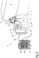
- FIG Fig. 3 A second embodiment of the loading system is shown in FIG Fig. 3 shown.
- This shows a loading station 5 with a loading device 16.
- the transport carriage 6 is also coupled to the coupling section 12.
- the coupling section 12 of the loading station 5 is formed by two lateral guides 14 and a stop 15 on the end face.
- On the A robot 4 is mounted on the robot attachment portion 7, the robot attachment portion 7 being the same as that of the first embodiment.
- the transport carriage 6 coupled to the coupling section 12 has a large number of holding devices 10, which are arranged horizontally on the transport carriage 6 in the form of holding rails at different heights. In three of the holding devices 10 there are three workpiece holders 8 at different heights, each in a holding position 11 in the transport trolley 6.
- Another workpiece holder 8 is positioned by the loading device 16 in a receiving position 9 relative to the robot fastening section 7, so that the robot 4 can hold onto the further workpiece holder 8 arranged workpieces 3 can accommodate.
- the illustrated loading system 1 is also positioned next to a device 2 in the form of a manufacturing machine.
- a loading system 1 is shown as a third embodiment, which consists of a loading station 5, a transport carriage 6 and a loading module 17.
- Fig. 4 shows the loading module 17 and the loading station 5 before they are joined together to form a unit.
- the loading station 5 corresponds to the loading station according to the first embodiment.
- the loading module 17 consists of two lateral guides 14.
- the loading device 16 is arranged between the lateral guides 14.
- a workpiece holder 8 with workpieces 3 is mounted on the loading device 16.
- the loading module 17 also has a coupling device 13 and an insertion device 18 on each of the lateral guides 14.
- three workpiece holders 8 are arranged in a holding position 11.
- the illustrated loading system 1 is also positioned next to a device 2 in the form of a manufacturing machine.
- the loading system 1 is shown in the variant shown as the third embodiment, consisting of a loading station 5, a loading module 17 and a transport trolley 6.
- the loading station 5 and the loading module 17 have already been combined to form a functional unit, ie the loading station 5 is retrofitted with a loading device 16.
- the loading system 1 shown further shows the transport carriage 6 before it is coupled to the coupling section 12 of the retrofitted loading station 5. It can be seen that a workpiece holder 8 with several workpieces 3 is in a receiving position 9 relative to the robot fastening section 7, so that the robot 4 mounted on the robot fastening section 7 can remove workpieces 3.
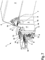
- Fig. 6 the charging system 1 is also shown in the variant shown as the third embodiment.
- the trolley 6 In contrast to Fig. 5 is in Fig. 6 the trolley 6 with the coupling section 12 of the charging module 17 coupled.
- the two coupling devices 13 are in a closed position, which prevent the transport carriage 6 from rolling out of the coupling section 12.
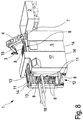
- Fig. 7 shows an application form of the loading system 1 according to the invention according to the third embodiment. It can be seen that a workpiece holder 8 with workpieces 3 is positioned on the two insertion devices 18. Also shown is a device 2, here a pallet, from which supplied workpieces 3 are removed and are inserted on the workpiece holders 7 held by the two insertion devices 18. The charging system 1 shown is also positioned next to a further device 2 in the form of a manufacturing machine.
- FIG. 8 Another application example of the loading system 1 is shown.
- the illustrated loading system 1 is positioned next to a device 2, here a pallet. Even if the depicted loading system 1 represents a loading system of the third embodiment, the application example shown can also take place with a loading system 1 according to each of the shown embodiments.
- Fig. 8 shows how workpieces 3 are removed from the workpiece holder 8 from their receiving position 9 by the robot 4 mounted on the robot fastening section 7 and placed in the device 2.
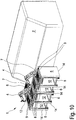
- a feeding system is shown in a fourth embodiment.
- the loading system 1 has a loading station 5 with two coupling sections 12.
- the loading station 5 also has a robot fastening section 7 on which a robot 4 is mounted.
- Each of the two coupling sections 12 is coupled to a transport carriage 6, so that the workpiece holders 8 with workpieces 3 located on the holding devices 10 of the transport carriage 6 are each located in a receiving position 9 with respect to the robot fastening portion 7.
- the charging system 1 is also arranged in a device 2, here a processing machine.
- Fig. 10 shows a loading system in a fifth embodiment.
- the loading station 5 has four coupling sections 12, a transport carriage 6 with workpiece holders 8 and workpieces 3 being coupled to each of the four coupling sections 12.
- Another transport carriage 6 is also coupled to a lateral, fifth coupling section 12.
- the fifth embodiment of the loading system also has two robot fastening sections 7, a robot 4 being mounted on each of the two robot fastening sections 7.
- the robot fastening sections 7 are each positioned between two coupling sections 12, so that two of the four workpiece holders 8 are in a receiving position 9 relative to one of the two robot fastening sections 7.
- the charging system 1 is also arranged at a device 2.
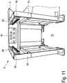
- Fig. 11 shows a loading station 5 of a loading system 1 according to the first embodiment.
- the loading station 5 has two lateral guides 14 and a stop 15 on the end face.
- the lateral guides 14 and the frontal stop 15 enclose the coupling section 12 on three sides.
- the robot fastening section 7. In contrast to that in FIG Fig. 1 No robot 4 is mounted on the robot mounting section 7 shown in the loading station 5 shown.
- a lateral guide rail 19 and a plurality of lateral guide rollers 20 are shown on each of the two lateral guides 14.
- the lateral guides 19 and the lateral guide rollers 20 are arranged on the side of the lateral guides 14 facing the coupling section 12.
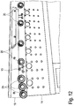
- FIG. 14 is a detailed view of a side guide 14 of FIG Fig. 11
- the loading station 5 shown here can be seen thereon, seven lateral guide rollers 20 and one lateral guide rail 19.
- the coupling device 13 is shown in the form of a lock cylinder. This can prevent the transport carriage 6 (not shown) from rolling out of the coupling section 12 by moving forward.
- the first three guide rollers 20 - that is, the guide rollers furthest away from the frontal stop 15 - are offset downward in the vertical direction compared to the four rear guide rollers 20.
- the first three guide rollers 20 are arranged at a slightly increasing angle of preferably at most 10 °.
Landscapes
- Engineering & Computer Science (AREA)
- Mechanical Engineering (AREA)
- Robotics (AREA)
- Automatic Assembly (AREA)
Claims (15)
- Système de chargement (1) pour charger un dispositif (2) de pièces (3) moyennant un robot (4), ledit système de chargement (1) comprenant une station de chargement (5) et au moins un chariot de transport 6),ladite station de chargement (5) comprenant une partie de fixation de robot (7) et étant adaptée de telle façon qu'elle est apte à tenir dans celle-ci, de façon répétable, un porte-pièce (8) de façon immobile et dans une position de préhension (9) définie par rapport à ladite partie de fixation de robot (7) depuis laquelle un robot (4) attaché à ladite partie de fixation de robot (7) peut saisir les pièces (3),ledit chariot de transport (6) étant doté d'au moins un dispositif porteur (10) pour porter un porte-pièce (8) dans une position de maintien (11),ladite station de chargement (5) comprenant un dispositif de chargement (16) qui est apte à transférer un porte-pièce (8) de manière indirect depuis la position de maintien (11) vers la position de préhension (9) dans ladite station de chargement (5), ledit dispositif de chargement (16) étant adaptée de façon qu'elle est apte à pousser et/ou tirer un porte-pièce (8) et ladite station de chargement (5) comprenant une partie de couplage (12) qui est apte à coupler le chariot de transport (6) à ladite station de chargement (5) moyennant un dispositif de couplage (13) de façon qu'après le couplage du chariot de transport (6) à ladite partie de couplage (12) un porte-outil (8) porté par le chariot de transport (6) dans la position de maintien (11) a été transféré dans la position de préhension (9) moyennant un mouvement horizontal ou vertical du porte-pièce (8).
- Système de chargement (1) selon la revendication 1,caractérisé en ce queladite partie de couplage (12) comprend au moins un organe de guidage latéral (14), de préférence deux organes de guidage latéral (14) pour ledit chariot de transport (6).
- Système de chargement (1) selon la revendication 1 ou 2,caractérisé en ce queladite partie de couplage (12) comprend au moins une butée frontale (15).
- Système de chargement (1) selon la revendication 2,caractérisé en ce queledit au moins un organe de guidage latéral (14) comprend au moins un rail de guidage latéral (19) et/ou un rouleau de guidage latéral (20).
- Système de chargement (1) selon l'une quelconque des revendications précédentes,caractérisé en ce queledit dispositif de couplage (13) est prévu sur ladite partie de couplage (12) de ladite station de chargement (5) et/ou sur ledit chariot de transport (6).
- Système de chargement (1) selon l'une quelconque des revendications précédentes,caractérisé en ce queledit chariot de transport (6) comprend plusieurs dispositifs porteurs (10), qui sont disposés à des hauteurs différentes du chariot de transport (6), pour porter des porte-pièces (8) dans des positions différentes de maintien (11) dans le chariot de transport (6).
- Système de chargement (1) selon l'une quelconque des revendications précédentes,caractérisé en ce queledit dispositif de chargement (16) est réalisé en forme de module de chargement (17) autonome qui est apte à être attaché sur ladite station de chargement (5), de préférence directement sur ladite partie de couplage (12) de ladite station de chargement (5).
- Système de chargement (1) selon l'une quelconque des revendications précédentes,caractérisé en ce queledit module de chargement (17) comprend une partie de couplage (12), qui de préférence correspond à ladite partie de couplage (12) de ladite station de chargement (5), pour le couplage d'un chariot de transport (6).
- Système de chargement (1) selon l'une quelconque des revendications précédentes,caractérisé en ce queladite station de chargement (5) comprend plusieurs parties de couplage (12).
- Système de chargement (1) selon l'une quelconque des revendications précédentes,caractérisé en ce queladite station de chargement (5) comprend au moins une autre partie de fixation de robot (7) adaptée pour la fixation d'un autre robot (4).
- Système de chargement (1) selon l'une quelconque des revendications précédentes,caractérisé en ce queladite partie de couplage (12) comprend un dispositif d'insertion (18) pour porte-pièces (8).
- Procédé pour charger un dispositif (2) de porte-pièces (3) en se servant du système de chargement (1) selon l'une quelconque des revendications précédentes, le procédé comprenant les étapes suivantes :a) charger le chariot de transport (6) d'au moins un porte-pièce (8) et d'au moins une pièce (3),b) déplacer le chariot de transport (6) à la station de chargement (5),c) coupler le chariot de transport (6) à ladite partie de couplage (12) de la station de chargement (5),d) après le couplage dans l'étape c), un retrait de ladite au moins une pièce (3) par le robot (4) et le chargement de celle-ci dans le dispositif (2) par le robot (4) étant effectué, le procédé étant mise en œuvre en interposant un déplacement d'au moins un porte-pièce (8) depuis la position de maintien (11) vers la position de préhension (9) moyennant le dispositif de chargement (16).
- Procédé selon la revendication 12,caractérisé en ce quel'étape a) est effectuée dans une autre station de chargement (5) par le robot (4) ou de façon manuelle.
- Procédé selon la revendication 12 ou 13,caractérisé en ce quepour le chargement d'un chariot de transport (6), le procédé est effectué en ordre inverse.
- Utilisation d'un système de chargement (1) selon l'une quelconque des revendications de dispositif précédentes pour le chargement d'un dispositif (2).
Priority Applications (1)
| Application Number | Priority Date | Filing Date | Title |
|---|---|---|---|
| PL16733027T PL3313624T3 (pl) | 2015-06-29 | 2016-06-21 | Układ obsadzający do narzędzi |
Applications Claiming Priority (2)
| Application Number | Priority Date | Filing Date | Title |
|---|---|---|---|
| DE102015110453.9A DE102015110453A1 (de) | 2015-06-29 | 2015-06-29 | Beschickungssystem für Werkstücke |
| PCT/EP2016/064326 WO2017001248A1 (fr) | 2015-06-29 | 2016-06-21 | Système de chargement pour pièces |
Publications (2)
| Publication Number | Publication Date |
|---|---|
| EP3313624A1 EP3313624A1 (fr) | 2018-05-02 |
| EP3313624B1 true EP3313624B1 (fr) | 2021-11-24 |
Family
ID=56289476
Family Applications (1)
| Application Number | Title | Priority Date | Filing Date |
|---|---|---|---|
| EP16733027.3A Active EP3313624B1 (fr) | 2015-06-29 | 2016-06-21 | Système de chargement pour pièces |
Country Status (8)
| Country | Link |
|---|---|
| US (1) | US11052500B2 (fr) |
| EP (1) | EP3313624B1 (fr) |
| DE (1) | DE102015110453A1 (fr) |
| DK (1) | DK3313624T3 (fr) |
| ES (1) | ES2901110T3 (fr) |
| HU (1) | HUE057704T2 (fr) |
| PL (1) | PL3313624T3 (fr) |
| WO (1) | WO2017001248A1 (fr) |
Families Citing this family (4)
| Publication number | Priority date | Publication date | Assignee | Title |
|---|---|---|---|---|
| DE102018122499A1 (de) * | 2018-09-14 | 2020-03-19 | HELLA GmbH & Co. KGaA | Einrichtung mit einem ersten und einem zweiten Roboter und Verfahren zu deren Betrieb |
| DE102019214088B4 (de) * | 2019-09-16 | 2022-12-08 | Deckel Maho Pfronten Gmbh | Handhabungsvorrichtung für eine werkzeugmaschine, handhabungseinrichtung und handhabungssystem |
| CN115478748A (zh) * | 2021-06-16 | 2022-12-16 | 三赢科技(深圳)有限公司 | 弹夹自动开合系统 |
| WO2023041184A1 (fr) * | 2021-09-20 | 2023-03-23 | Abb Schweiz Ag | Unité de base pour système d'alimentation, système d'alimentation, système industriel, et procédé de manipulation d'un système d'alimentation |
Citations (2)
| Publication number | Priority date | Publication date | Assignee | Title |
|---|---|---|---|---|
| DE19805206A1 (de) * | 1998-02-10 | 1999-08-12 | Artur Baer Gmbh | Handhabungsvorrichtung zur Zuführung und/oder Abführung von Werkstücken |
| WO2013087554A1 (fr) * | 2011-12-12 | 2013-06-20 | Klingelnberg Ag | Dispositif et procédé permettant de transférer des pièces à usiner présentées en packs vers une machine d'usinage au moyen d'un robot |
Family Cites Families (9)
| Publication number | Priority date | Publication date | Assignee | Title |
|---|---|---|---|---|
| JPH04310384A (ja) | 1991-04-09 | 1992-11-02 | Toyota Motor Corp | 複腕ロボット |
| DE4409532C2 (de) | 1994-03-21 | 1996-09-26 | Felsomat Gmbh & Co Kg | Handhabungssystem |
| US6592318B2 (en) * | 2001-07-13 | 2003-07-15 | Asm America, Inc. | Docking cart with integrated load port |
| KR100555620B1 (ko) * | 2003-10-28 | 2006-03-03 | 주식회사 디엠에스 | 기판 운반시스템 및 운반방법 |
| DE102005009283A1 (de) * | 2005-02-22 | 2006-08-24 | Ex-Cell-O Gmbh | Werkzeugmaschinensystem, verfahrbare Belade-/Entladevorrichtung und Verfahren zur Bereitstellung/Entnahme von Gegenständen von/an Bearbeitungsstationen eines Werkzeugmaschinensystems |
| WO2007089269A2 (fr) * | 2005-06-27 | 2007-08-09 | Matrix Scientific, Llc | Système et procédé de manutention de cages non palettisables |
| JP4606388B2 (ja) * | 2006-06-12 | 2011-01-05 | 川崎重工業株式会社 | 基板移載装置の搬送系ユニット |
| US9190304B2 (en) * | 2011-05-19 | 2015-11-17 | Brooks Automation, Inc. | Dynamic storage and transfer system integrated with autonomous guided/roving vehicle |
| TWM435718U (en) * | 2012-04-02 | 2012-08-11 | Gudeng Prec Ind Co Ltd | The wafer cassette conveyance apparatus |
-
2015
- 2015-06-29 DE DE102015110453.9A patent/DE102015110453A1/de not_active Withdrawn
-
2016
- 2016-06-21 US US15/740,759 patent/US11052500B2/en active Active
- 2016-06-21 WO PCT/EP2016/064326 patent/WO2017001248A1/fr active Application Filing
- 2016-06-21 EP EP16733027.3A patent/EP3313624B1/fr active Active
- 2016-06-21 PL PL16733027T patent/PL3313624T3/pl unknown
- 2016-06-21 DK DK16733027.3T patent/DK3313624T3/da active
- 2016-06-21 HU HUE16733027A patent/HUE057704T2/hu unknown
- 2016-06-21 ES ES16733027T patent/ES2901110T3/es active Active
Patent Citations (2)
| Publication number | Priority date | Publication date | Assignee | Title |
|---|---|---|---|---|
| DE19805206A1 (de) * | 1998-02-10 | 1999-08-12 | Artur Baer Gmbh | Handhabungsvorrichtung zur Zuführung und/oder Abführung von Werkstücken |
| WO2013087554A1 (fr) * | 2011-12-12 | 2013-06-20 | Klingelnberg Ag | Dispositif et procédé permettant de transférer des pièces à usiner présentées en packs vers une machine d'usinage au moyen d'un robot |
Also Published As
| Publication number | Publication date |
|---|---|
| DE102015110453A1 (de) | 2016-12-29 |
| PL3313624T3 (pl) | 2022-01-31 |
| US20180185974A1 (en) | 2018-07-05 |
| DK3313624T3 (da) | 2022-02-14 |
| EP3313624A1 (fr) | 2018-05-02 |
| ES2901110T3 (es) | 2022-03-21 |
| HUE057704T2 (hu) | 2022-05-28 |
| WO2017001248A1 (fr) | 2017-01-05 |
| US11052500B2 (en) | 2021-07-06 |
Similar Documents
| Publication | Publication Date | Title |
|---|---|---|
| EP2492041B1 (fr) | Dispositif avec un dispositif d'usinage de tuyau ; Méthode de déchargement d'un tuyau utilisant un tel dispositif | |
| EP3313624B1 (fr) | Système de chargement pour pièces | |
| EP3319742B1 (fr) | Dispositif de stockage d'outils de pliage | |
| DE102012016721A1 (de) | Schnellwechselsysteme für eine werkstückspezifische Handhabungsvorrichtung. werkstückspezifische Handhabungsvorrichtung mit denselben sowie Ablagegestell für selbige | |
| DE102007035743B4 (de) | Bearbeitungsstation zum Bearbeiten von plattenförmigen Werkstücken | |
| DE3220911C2 (de) | Schnellwechsel- und/oder Spannvorrichtung für die Formwerkzeuge von Spritzgießmaschinen | |
| DE202008012632U1 (de) | Bearbeitungsmaschine für sechsseitige Bearbeitung | |
| DE602005001541T2 (de) | Klemmvorrichtung für einen Palettenwechsler | |
| DE3542496A1 (de) | Verfahren und vorrichtung zum zufuehren von montageteilen | |
| DE4232289C2 (de) | Verfahren und Vorrichtung zum Verschwenken eines Fensterrahmens im Bereich einer Eckenputzmaschine | |
| DE102018111731A1 (de) | Raupenzugziehmaschine und Ziehverfahren | |
| DE102013223252B4 (de) | Maschinelle Werkstück-Transfervorrichtung sowie maschinelle Entladevorrichtung und maschinelle Anordnung zum Bearbeiten von Werkstücken mit einer derartigen Werkstück-Transfervorrichtung | |
| DE102007038622A1 (de) | Stapelzelle | |
| DE102013006315A1 (de) | Kleinteil-Vereinzelungsverfahren und -vorrichtung | |
| DE2400235C2 (de) | An einer Senkrechträummaschine angeordnete Fördereinrichtung zum Hochfördern von Werkstücken vor mindestens eine Werkstückvorlage | |
| EP3456443B1 (fr) | Dispositif d'alimentation en matériau en barres | |
| EP2371480B1 (fr) | Centre de traitement de profilés | |
| DE2648296C3 (de) | Rahmenlose Halte- und Tragevorrichtung für die Gießbleche einer Schokoladengießanlage | |
| WO2019057230A2 (fr) | Machine de matriçage, un système d'adaptation d'outil de matriçage, outil de matriçage, procédé d'adaptation d'une machine de matriçage, procédé d'adaptation de machine de matriçage, procédé de fonctionnement d'une machine de matriçage et utilisation d'un outil de matriçage inférieur | |
| DE102013009176B3 (de) | Werkstückzufuhrvorrichtung und Verwendung | |
| AT523802B1 (de) | Mattenschweißanlage zur Herstellung von Betonstahlmatten | |
| WO2006045284A1 (fr) | Dispositif de changement d'outillage automatique | |
| DE202012102690U1 (de) | Vorrichtung zur Gehäusemontage von Aufsatz-Rollladenkästen | |
| DE3728628C2 (fr) | ||
| DE2166857A1 (de) | Montagevorrichtung fuer moebelbeschlaege, insbesondere scharniere |
Legal Events
| Date | Code | Title | Description |
|---|---|---|---|
| STAA | Information on the status of an ep patent application or granted ep patent |
Free format text: STATUS: THE INTERNATIONAL PUBLICATION HAS BEEN MADE |
|
| PUAI | Public reference made under article 153(3) epc to a published international application that has entered the european phase |
Free format text: ORIGINAL CODE: 0009012 |
|
| STAA | Information on the status of an ep patent application or granted ep patent |
Free format text: STATUS: REQUEST FOR EXAMINATION WAS MADE |
|
| 17P | Request for examination filed |
Effective date: 20180125 |
|
| AK | Designated contracting states |
Kind code of ref document: A1 Designated state(s): AL AT BE BG CH CY CZ DE DK EE ES FI FR GB GR HR HU IE IS IT LI LT LU LV MC MK MT NL NO PL PT RO RS SE SI SK SM TR |
|
| AX | Request for extension of the european patent |
Extension state: BA ME |
|
| DAV | Request for validation of the european patent (deleted) | ||
| DAX | Request for extension of the european patent (deleted) | ||
| STAA | Information on the status of an ep patent application or granted ep patent |
Free format text: STATUS: EXAMINATION IS IN PROGRESS |
|
| 17Q | First examination report despatched |
Effective date: 20190910 |
|
| GRAP | Despatch of communication of intention to grant a patent |
Free format text: ORIGINAL CODE: EPIDOSNIGR1 |
|
| STAA | Information on the status of an ep patent application or granted ep patent |
Free format text: STATUS: GRANT OF PATENT IS INTENDED |
|
| INTG | Intention to grant announced |
Effective date: 20201009 |
|
| GRAJ | Information related to disapproval of communication of intention to grant by the applicant or resumption of examination proceedings by the epo deleted |
Free format text: ORIGINAL CODE: EPIDOSDIGR1 |
|
| STAA | Information on the status of an ep patent application or granted ep patent |
Free format text: STATUS: EXAMINATION IS IN PROGRESS |
|
| GRAP | Despatch of communication of intention to grant a patent |
Free format text: ORIGINAL CODE: EPIDOSNIGR1 |
|
| STAA | Information on the status of an ep patent application or granted ep patent |
Free format text: STATUS: GRANT OF PATENT IS INTENDED |
|
| INTC | Intention to grant announced (deleted) | ||
| INTG | Intention to grant announced |
Effective date: 20210324 |
|
| GRAJ | Information related to disapproval of communication of intention to grant by the applicant or resumption of examination proceedings by the epo deleted |
Free format text: ORIGINAL CODE: EPIDOSDIGR1 |
|
| STAA | Information on the status of an ep patent application or granted ep patent |
Free format text: STATUS: EXAMINATION IS IN PROGRESS |
|
| GRAJ | Information related to disapproval of communication of intention to grant by the applicant or resumption of examination proceedings by the epo deleted |
Free format text: ORIGINAL CODE: EPIDOSDIGR1 |
|
| GRAP | Despatch of communication of intention to grant a patent |
Free format text: ORIGINAL CODE: EPIDOSNIGR1 |
|
| GRAP | Despatch of communication of intention to grant a patent |
Free format text: ORIGINAL CODE: EPIDOSNIGR1 |
|
| STAA | Information on the status of an ep patent application or granted ep patent |
Free format text: STATUS: GRANT OF PATENT IS INTENDED |
|
| INTC | Intention to grant announced (deleted) | ||
| INTG | Intention to grant announced |
Effective date: 20210909 |
|
| GRAS | Grant fee paid |
Free format text: ORIGINAL CODE: EPIDOSNIGR3 |
|
| GRAA | (expected) grant |
Free format text: ORIGINAL CODE: 0009210 |
|
| STAA | Information on the status of an ep patent application or granted ep patent |
Free format text: STATUS: THE PATENT HAS BEEN GRANTED |
|
| AK | Designated contracting states |
Kind code of ref document: B1 Designated state(s): AL AT BE BG CH CY CZ DE DK EE ES FI FR GB GR HR HU IE IS IT LI LT LU LV MC MK MT NL NO PL PT RO RS SE SI SK SM TR |
|
| REG | Reference to a national code |
Ref country code: GB Ref legal event code: FG4D Free format text: NOT ENGLISH |
|
| REG | Reference to a national code |
Ref country code: AT Ref legal event code: REF Ref document number: 1449501 Country of ref document: AT Kind code of ref document: T Effective date: 20211215 |
|
| REG | Reference to a national code |
Ref country code: DE Ref legal event code: R096 Ref document number: 502016014194 Country of ref document: DE |
|
| REG | Reference to a national code |
Ref country code: IE Ref legal event code: FG4D Free format text: LANGUAGE OF EP DOCUMENT: GERMAN |
|
| REG | Reference to a national code |
Ref country code: NL Ref legal event code: FP |
|
| REG | Reference to a national code |
Ref country code: DK Ref legal event code: T3 Effective date: 20220211 |
|
| REG | Reference to a national code |
Ref country code: FI Ref legal event code: FGE |
|
| REG | Reference to a national code |
Ref country code: SE Ref legal event code: TRGR |
|
| REG | Reference to a national code |
Ref country code: ES Ref legal event code: FG2A Ref document number: 2901110 Country of ref document: ES Kind code of ref document: T3 Effective date: 20220321 |
|
| REG | Reference to a national code |
Ref country code: LT Ref legal event code: MG9D |
|
| REG | Reference to a national code |
Ref country code: NO Ref legal event code: T2 Effective date: 20211124 |
|
| PG25 | Lapsed in a contracting state [announced via postgrant information from national office to epo] |
Ref country code: RS Free format text: LAPSE BECAUSE OF FAILURE TO SUBMIT A TRANSLATION OF THE DESCRIPTION OR TO PAY THE FEE WITHIN THE PRESCRIBED TIME-LIMIT Effective date: 20211124 Ref country code: LT Free format text: LAPSE BECAUSE OF FAILURE TO SUBMIT A TRANSLATION OF THE DESCRIPTION OR TO PAY THE FEE WITHIN THE PRESCRIBED TIME-LIMIT Effective date: 20211124 Ref country code: BG Free format text: LAPSE BECAUSE OF FAILURE TO SUBMIT A TRANSLATION OF THE DESCRIPTION OR TO PAY THE FEE WITHIN THE PRESCRIBED TIME-LIMIT Effective date: 20220224 |
|
| REG | Reference to a national code |
Ref country code: HU Ref legal event code: AG4A Ref document number: E057704 Country of ref document: HU |
|
| PG25 | Lapsed in a contracting state [announced via postgrant information from national office to epo] |
Ref country code: IS Free format text: LAPSE BECAUSE OF FAILURE TO SUBMIT A TRANSLATION OF THE DESCRIPTION OR TO PAY THE FEE WITHIN THE PRESCRIBED TIME-LIMIT Effective date: 20220324 Ref country code: PT Free format text: LAPSE BECAUSE OF FAILURE TO SUBMIT A TRANSLATION OF THE DESCRIPTION OR TO PAY THE FEE WITHIN THE PRESCRIBED TIME-LIMIT Effective date: 20220324 Ref country code: LV Free format text: LAPSE BECAUSE OF FAILURE TO SUBMIT A TRANSLATION OF THE DESCRIPTION OR TO PAY THE FEE WITHIN THE PRESCRIBED TIME-LIMIT Effective date: 20211124 Ref country code: HR Free format text: LAPSE BECAUSE OF FAILURE TO SUBMIT A TRANSLATION OF THE DESCRIPTION OR TO PAY THE FEE WITHIN THE PRESCRIBED TIME-LIMIT Effective date: 20211124 Ref country code: GR Free format text: LAPSE BECAUSE OF FAILURE TO SUBMIT A TRANSLATION OF THE DESCRIPTION OR TO PAY THE FEE WITHIN THE PRESCRIBED TIME-LIMIT Effective date: 20220225 |
|
| PG25 | Lapsed in a contracting state [announced via postgrant information from national office to epo] |
Ref country code: SM Free format text: LAPSE BECAUSE OF FAILURE TO SUBMIT A TRANSLATION OF THE DESCRIPTION OR TO PAY THE FEE WITHIN THE PRESCRIBED TIME-LIMIT Effective date: 20211124 Ref country code: SK Free format text: LAPSE BECAUSE OF FAILURE TO SUBMIT A TRANSLATION OF THE DESCRIPTION OR TO PAY THE FEE WITHIN THE PRESCRIBED TIME-LIMIT Effective date: 20211124 Ref country code: RO Free format text: LAPSE BECAUSE OF FAILURE TO SUBMIT A TRANSLATION OF THE DESCRIPTION OR TO PAY THE FEE WITHIN THE PRESCRIBED TIME-LIMIT Effective date: 20211124 Ref country code: EE Free format text: LAPSE BECAUSE OF FAILURE TO SUBMIT A TRANSLATION OF THE DESCRIPTION OR TO PAY THE FEE WITHIN THE PRESCRIBED TIME-LIMIT Effective date: 20211124 Ref country code: CZ Free format text: LAPSE BECAUSE OF FAILURE TO SUBMIT A TRANSLATION OF THE DESCRIPTION OR TO PAY THE FEE WITHIN THE PRESCRIBED TIME-LIMIT Effective date: 20211124 |
|
| REG | Reference to a national code |
Ref country code: DE Ref legal event code: R097 Ref document number: 502016014194 Country of ref document: DE |
|
| PLBE | No opposition filed within time limit |
Free format text: ORIGINAL CODE: 0009261 |
|
| STAA | Information on the status of an ep patent application or granted ep patent |
Free format text: STATUS: NO OPPOSITION FILED WITHIN TIME LIMIT |
|
| PG25 | Lapsed in a contracting state [announced via postgrant information from national office to epo] |
Ref country code: AL Free format text: LAPSE BECAUSE OF FAILURE TO SUBMIT A TRANSLATION OF THE DESCRIPTION OR TO PAY THE FEE WITHIN THE PRESCRIBED TIME-LIMIT Effective date: 20211124 |
|
| 26N | No opposition filed |
Effective date: 20220825 |
|
| PG25 | Lapsed in a contracting state [announced via postgrant information from national office to epo] |
Ref country code: SI Free format text: LAPSE BECAUSE OF FAILURE TO SUBMIT A TRANSLATION OF THE DESCRIPTION OR TO PAY THE FEE WITHIN THE PRESCRIBED TIME-LIMIT Effective date: 20211124 |
|
| REG | Reference to a national code |
Ref country code: FI Ref legal event code: MAE |
|
| REG | Reference to a national code |
Ref country code: NO Ref legal event code: MMEP Ref country code: DK Ref legal event code: EBP Effective date: 20220630 |
|
| PG25 | Lapsed in a contracting state [announced via postgrant information from national office to epo] |
Ref country code: MC Free format text: LAPSE BECAUSE OF FAILURE TO SUBMIT A TRANSLATION OF THE DESCRIPTION OR TO PAY THE FEE WITHIN THE PRESCRIBED TIME-LIMIT Effective date: 20211124 Ref country code: FI Free format text: LAPSE BECAUSE OF NON-PAYMENT OF DUE FEES Effective date: 20220621 |
|
| REG | Reference to a national code |
Ref country code: CH Ref legal event code: PL Ref country code: SE Ref legal event code: EUG |
|
| REG | Reference to a national code |
Ref country code: NL Ref legal event code: MM Effective date: 20220701 |
|
| REG | Reference to a national code |
Ref country code: BE Ref legal event code: MM Effective date: 20220630 |
|
| GBPC | Gb: european patent ceased through non-payment of renewal fee |
Effective date: 20220621 |
|
| PG25 | Lapsed in a contracting state [announced via postgrant information from national office to epo] |
Ref country code: NL Free format text: LAPSE BECAUSE OF NON-PAYMENT OF DUE FEES Effective date: 20220701 |
|
| PG25 | Lapsed in a contracting state [announced via postgrant information from national office to epo] |
Ref country code: SE Free format text: LAPSE BECAUSE OF NON-PAYMENT OF DUE FEES Effective date: 20220622 Ref country code: NO Free format text: LAPSE BECAUSE OF NON-PAYMENT OF DUE FEES Effective date: 20220630 Ref country code: LU Free format text: LAPSE BECAUSE OF NON-PAYMENT OF DUE FEES Effective date: 20220621 Ref country code: LI Free format text: LAPSE BECAUSE OF NON-PAYMENT OF DUE FEES Effective date: 20220630 Ref country code: IE Free format text: LAPSE BECAUSE OF NON-PAYMENT OF DUE FEES Effective date: 20220621 Ref country code: CH Free format text: LAPSE BECAUSE OF NON-PAYMENT OF DUE FEES Effective date: 20220630 |
|
| PG25 | Lapsed in a contracting state [announced via postgrant information from national office to epo] |
Ref country code: GB Free format text: LAPSE BECAUSE OF NON-PAYMENT OF DUE FEES Effective date: 20220621 Ref country code: BE Free format text: LAPSE BECAUSE OF NON-PAYMENT OF DUE FEES Effective date: 20220630 |
|
| PG25 | Lapsed in a contracting state [announced via postgrant information from national office to epo] |
Ref country code: DK Free format text: LAPSE BECAUSE OF NON-PAYMENT OF DUE FEES Effective date: 20220630 |
|
| PGFP | Annual fee paid to national office [announced via postgrant information from national office to epo] |
Ref country code: FR Payment date: 20230621 Year of fee payment: 8 Ref country code: DE Payment date: 20230627 Year of fee payment: 8 |
|
| REG | Reference to a national code |
Ref country code: AT Ref legal event code: MM01 Ref document number: 1449501 Country of ref document: AT Kind code of ref document: T Effective date: 20220621 |
|
| PGFP | Annual fee paid to national office [announced via postgrant information from national office to epo] |
Ref country code: PL Payment date: 20230609 Year of fee payment: 8 Ref country code: HU Payment date: 20230614 Year of fee payment: 8 |
|
| PG25 | Lapsed in a contracting state [announced via postgrant information from national office to epo] |
Ref country code: AT Free format text: LAPSE BECAUSE OF NON-PAYMENT OF DUE FEES Effective date: 20220621 |
|
| PGFP | Annual fee paid to national office [announced via postgrant information from national office to epo] |
Ref country code: IT Payment date: 20230630 Year of fee payment: 8 Ref country code: ES Payment date: 20230719 Year of fee payment: 8 |
|
| PG25 | Lapsed in a contracting state [announced via postgrant information from national office to epo] |
Ref country code: MK Free format text: LAPSE BECAUSE OF FAILURE TO SUBMIT A TRANSLATION OF THE DESCRIPTION OR TO PAY THE FEE WITHIN THE PRESCRIBED TIME-LIMIT Effective date: 20211124 Ref country code: CY Free format text: LAPSE BECAUSE OF FAILURE TO SUBMIT A TRANSLATION OF THE DESCRIPTION OR TO PAY THE FEE WITHIN THE PRESCRIBED TIME-LIMIT Effective date: 20211124 |