EP3313595B1 - Dispositif de fabrication additive d'au moins un objet tridimensionnel - Google Patents
Dispositif de fabrication additive d'au moins un objet tridimensionnel Download PDFInfo
- Publication number
- EP3313595B1 EP3313595B1 EP16731125.7A EP16731125A EP3313595B1 EP 3313595 B1 EP3313595 B1 EP 3313595B1 EP 16731125 A EP16731125 A EP 16731125A EP 3313595 B1 EP3313595 B1 EP 3313595B1
- Authority
- EP
- European Patent Office
- Prior art keywords
- building material
- coating
- layer
- energy beam
- material layer
- Prior art date
- Legal status (The legal status is an assumption and is not a legal conclusion. Google has not performed a legal analysis and makes no representation as to the accuracy of the status listed.)
- Active
Links
- 238000004519 manufacturing process Methods 0.000 title claims description 18
- 239000000654 additive Substances 0.000 title description 2
- 230000000996 additive effect Effects 0.000 title description 2
- 238000000576 coating method Methods 0.000 claims description 166
- 239000004566 building material Substances 0.000 claims description 148
- 239000011248 coating agent Substances 0.000 claims description 104
- 238000001514 detection method Methods 0.000 claims description 71
- 238000000034 method Methods 0.000 claims description 60
- 230000005855 radiation Effects 0.000 claims description 25
- 238000010276 construction Methods 0.000 claims description 21
- 238000007711 solidification Methods 0.000 claims description 14
- 230000008023 solidification Effects 0.000 claims description 14
- 238000004140 cleaning Methods 0.000 claims description 13
- 230000001681 protective effect Effects 0.000 claims description 11
- 230000003287 optical effect Effects 0.000 claims description 9
- 238000002844 melting Methods 0.000 claims description 8
- 230000008018 melting Effects 0.000 claims description 8
- 239000004035 construction material Substances 0.000 claims description 4
- 238000011156 evaluation Methods 0.000 claims description 3
- 239000012530 fluid Substances 0.000 claims description 3
- 239000012535 impurity Substances 0.000 claims description 2
- 239000007789 gas Substances 0.000 description 13
- 238000007596 consolidation process Methods 0.000 description 5
- 230000006735 deficit Effects 0.000 description 5
- IJGRMHOSHXDMSA-UHFFFAOYSA-N Atomic nitrogen Chemical compound N#N IJGRMHOSHXDMSA-UHFFFAOYSA-N 0.000 description 4
- 238000000110 selective laser sintering Methods 0.000 description 4
- 239000002245 particle Substances 0.000 description 3
- 239000000843 powder Substances 0.000 description 3
- XKRFYHLGVUSROY-UHFFFAOYSA-N Argon Chemical compound [Ar] XKRFYHLGVUSROY-UHFFFAOYSA-N 0.000 description 2
- CURLTUGMZLYLDI-UHFFFAOYSA-N Carbon dioxide Chemical compound O=C=O CURLTUGMZLYLDI-UHFFFAOYSA-N 0.000 description 2
- 230000001133 acceleration Effects 0.000 description 2
- 238000004458 analytical method Methods 0.000 description 2
- 230000003466 anti-cipated effect Effects 0.000 description 2
- 238000011109 contamination Methods 0.000 description 2
- 230000007547 defect Effects 0.000 description 2
- 238000010586 diagram Methods 0.000 description 2
- 238000005286 illumination Methods 0.000 description 2
- 238000010309 melting process Methods 0.000 description 2
- 239000002184 metal Substances 0.000 description 2
- 239000000203 mixture Substances 0.000 description 2
- 229910052757 nitrogen Inorganic materials 0.000 description 2
- 238000004904 shortening Methods 0.000 description 2
- 229910052786 argon Inorganic materials 0.000 description 1
- 239000001569 carbon dioxide Substances 0.000 description 1
- 229910002092 carbon dioxide Inorganic materials 0.000 description 1
- 230000008878 coupling Effects 0.000 description 1
- 238000010168 coupling process Methods 0.000 description 1
- 238000005859 coupling reaction Methods 0.000 description 1
- 230000001419 dependent effect Effects 0.000 description 1
- 230000001066 destructive effect Effects 0.000 description 1
- 238000005516 engineering process Methods 0.000 description 1
- 230000010354 integration Effects 0.000 description 1
- 239000000463 material Substances 0.000 description 1
- 239000000155 melt Substances 0.000 description 1
- 230000008092 positive effect Effects 0.000 description 1
- 239000000779 smoke Substances 0.000 description 1
Images


Classifications
-
- B—PERFORMING OPERATIONS; TRANSPORTING
- B29—WORKING OF PLASTICS; WORKING OF SUBSTANCES IN A PLASTIC STATE IN GENERAL
- B29C—SHAPING OR JOINING OF PLASTICS; SHAPING OF MATERIAL IN A PLASTIC STATE, NOT OTHERWISE PROVIDED FOR; AFTER-TREATMENT OF THE SHAPED PRODUCTS, e.g. REPAIRING
- B29C64/00—Additive manufacturing, i.e. manufacturing of three-dimensional [3D] objects by additive deposition, additive agglomeration or additive layering, e.g. by 3D printing, stereolithography or selective laser sintering
- B29C64/10—Processes of additive manufacturing
- B29C64/141—Processes of additive manufacturing using only solid materials
- B29C64/153—Processes of additive manufacturing using only solid materials using layers of powder being selectively joined, e.g. by selective laser sintering or melting
-
- B—PERFORMING OPERATIONS; TRANSPORTING
- B22—CASTING; POWDER METALLURGY
- B22F—WORKING METALLIC POWDER; MANUFACTURE OF ARTICLES FROM METALLIC POWDER; MAKING METALLIC POWDER; APPARATUS OR DEVICES SPECIALLY ADAPTED FOR METALLIC POWDER
- B22F10/00—Additive manufacturing of workpieces or articles from metallic powder
- B22F10/20—Direct sintering or melting
- B22F10/28—Powder bed fusion, e.g. selective laser melting [SLM] or electron beam melting [EBM]
-
- B—PERFORMING OPERATIONS; TRANSPORTING
- B22—CASTING; POWDER METALLURGY
- B22F—WORKING METALLIC POWDER; MANUFACTURE OF ARTICLES FROM METALLIC POWDER; MAKING METALLIC POWDER; APPARATUS OR DEVICES SPECIALLY ADAPTED FOR METALLIC POWDER
- B22F10/00—Additive manufacturing of workpieces or articles from metallic powder
- B22F10/30—Process control
- B22F10/36—Process control of energy beam parameters
-
- B—PERFORMING OPERATIONS; TRANSPORTING
- B22—CASTING; POWDER METALLURGY
- B22F—WORKING METALLIC POWDER; MANUFACTURE OF ARTICLES FROM METALLIC POWDER; MAKING METALLIC POWDER; APPARATUS OR DEVICES SPECIALLY ADAPTED FOR METALLIC POWDER
- B22F10/00—Additive manufacturing of workpieces or articles from metallic powder
- B22F10/30—Process control
- B22F10/37—Process control of powder bed aspects, e.g. density
-
- B—PERFORMING OPERATIONS; TRANSPORTING
- B22—CASTING; POWDER METALLURGY
- B22F—WORKING METALLIC POWDER; MANUFACTURE OF ARTICLES FROM METALLIC POWDER; MAKING METALLIC POWDER; APPARATUS OR DEVICES SPECIALLY ADAPTED FOR METALLIC POWDER
- B22F12/00—Apparatus or devices specially adapted for additive manufacturing; Auxiliary means for additive manufacturing; Combinations of additive manufacturing apparatus or devices with other processing apparatus or devices
- B22F12/22—Driving means
- B22F12/222—Driving means for motion along a direction orthogonal to the plane of a layer
-
- B—PERFORMING OPERATIONS; TRANSPORTING
- B22—CASTING; POWDER METALLURGY
- B22F—WORKING METALLIC POWDER; MANUFACTURE OF ARTICLES FROM METALLIC POWDER; MAKING METALLIC POWDER; APPARATUS OR DEVICES SPECIALLY ADAPTED FOR METALLIC POWDER
- B22F12/00—Apparatus or devices specially adapted for additive manufacturing; Auxiliary means for additive manufacturing; Combinations of additive manufacturing apparatus or devices with other processing apparatus or devices
- B22F12/60—Planarisation devices; Compression devices
- B22F12/67—Blades
-
- B—PERFORMING OPERATIONS; TRANSPORTING
- B22—CASTING; POWDER METALLURGY
- B22F—WORKING METALLIC POWDER; MANUFACTURE OF ARTICLES FROM METALLIC POWDER; MAKING METALLIC POWDER; APPARATUS OR DEVICES SPECIALLY ADAPTED FOR METALLIC POWDER
- B22F12/00—Apparatus or devices specially adapted for additive manufacturing; Auxiliary means for additive manufacturing; Combinations of additive manufacturing apparatus or devices with other processing apparatus or devices
- B22F12/90—Means for process control, e.g. cameras or sensors
-
- B—PERFORMING OPERATIONS; TRANSPORTING
- B23—MACHINE TOOLS; METAL-WORKING NOT OTHERWISE PROVIDED FOR
- B23K—SOLDERING OR UNSOLDERING; WELDING; CLADDING OR PLATING BY SOLDERING OR WELDING; CUTTING BY APPLYING HEAT LOCALLY, e.g. FLAME CUTTING; WORKING BY LASER BEAM
- B23K26/00—Working by laser beam, e.g. welding, cutting or boring
- B23K26/0093—Working by laser beam, e.g. welding, cutting or boring combined with mechanical machining or metal-working covered by other subclasses than B23K
-
- B—PERFORMING OPERATIONS; TRANSPORTING
- B23—MACHINE TOOLS; METAL-WORKING NOT OTHERWISE PROVIDED FOR
- B23K—SOLDERING OR UNSOLDERING; WELDING; CLADDING OR PLATING BY SOLDERING OR WELDING; CUTTING BY APPLYING HEAT LOCALLY, e.g. FLAME CUTTING; WORKING BY LASER BEAM
- B23K26/00—Working by laser beam, e.g. welding, cutting or boring
- B23K26/02—Positioning or observing the workpiece, e.g. with respect to the point of impact; Aligning, aiming or focusing the laser beam
- B23K26/03—Observing, e.g. monitoring, the workpiece
- B23K26/032—Observing, e.g. monitoring, the workpiece using optical means
-
- B—PERFORMING OPERATIONS; TRANSPORTING
- B23—MACHINE TOOLS; METAL-WORKING NOT OTHERWISE PROVIDED FOR
- B23K—SOLDERING OR UNSOLDERING; WELDING; CLADDING OR PLATING BY SOLDERING OR WELDING; CUTTING BY APPLYING HEAT LOCALLY, e.g. FLAME CUTTING; WORKING BY LASER BEAM
- B23K26/00—Working by laser beam, e.g. welding, cutting or boring
- B23K26/16—Removal of by-products, e.g. particles or vapours produced during treatment of a workpiece
-
- B—PERFORMING OPERATIONS; TRANSPORTING
- B23—MACHINE TOOLS; METAL-WORKING NOT OTHERWISE PROVIDED FOR
- B23K—SOLDERING OR UNSOLDERING; WELDING; CLADDING OR PLATING BY SOLDERING OR WELDING; CUTTING BY APPLYING HEAT LOCALLY, e.g. FLAME CUTTING; WORKING BY LASER BEAM
- B23K26/00—Working by laser beam, e.g. welding, cutting or boring
- B23K26/34—Laser welding for purposes other than joining
- B23K26/342—Build-up welding
-
- B—PERFORMING OPERATIONS; TRANSPORTING
- B29—WORKING OF PLASTICS; WORKING OF SUBSTANCES IN A PLASTIC STATE IN GENERAL
- B29C—SHAPING OR JOINING OF PLASTICS; SHAPING OF MATERIAL IN A PLASTIC STATE, NOT OTHERWISE PROVIDED FOR; AFTER-TREATMENT OF THE SHAPED PRODUCTS, e.g. REPAIRING
- B29C64/00—Additive manufacturing, i.e. manufacturing of three-dimensional [3D] objects by additive deposition, additive agglomeration or additive layering, e.g. by 3D printing, stereolithography or selective laser sintering
- B29C64/30—Auxiliary operations or equipment
- B29C64/35—Cleaning
-
- B—PERFORMING OPERATIONS; TRANSPORTING
- B29—WORKING OF PLASTICS; WORKING OF SUBSTANCES IN A PLASTIC STATE IN GENERAL
- B29C—SHAPING OR JOINING OF PLASTICS; SHAPING OF MATERIAL IN A PLASTIC STATE, NOT OTHERWISE PROVIDED FOR; AFTER-TREATMENT OF THE SHAPED PRODUCTS, e.g. REPAIRING
- B29C64/00—Additive manufacturing, i.e. manufacturing of three-dimensional [3D] objects by additive deposition, additive agglomeration or additive layering, e.g. by 3D printing, stereolithography or selective laser sintering
- B29C64/30—Auxiliary operations or equipment
- B29C64/386—Data acquisition or data processing for additive manufacturing
- B29C64/393—Data acquisition or data processing for additive manufacturing for controlling or regulating additive manufacturing processes
-
- B—PERFORMING OPERATIONS; TRANSPORTING
- B33—ADDITIVE MANUFACTURING TECHNOLOGY
- B33Y—ADDITIVE MANUFACTURING, i.e. MANUFACTURING OF THREE-DIMENSIONAL [3-D] OBJECTS BY ADDITIVE DEPOSITION, ADDITIVE AGGLOMERATION OR ADDITIVE LAYERING, e.g. BY 3-D PRINTING, STEREOLITHOGRAPHY OR SELECTIVE LASER SINTERING
- B33Y10/00—Processes of additive manufacturing
-
- B—PERFORMING OPERATIONS; TRANSPORTING
- B33—ADDITIVE MANUFACTURING TECHNOLOGY
- B33Y—ADDITIVE MANUFACTURING, i.e. MANUFACTURING OF THREE-DIMENSIONAL [3-D] OBJECTS BY ADDITIVE DEPOSITION, ADDITIVE AGGLOMERATION OR ADDITIVE LAYERING, e.g. BY 3-D PRINTING, STEREOLITHOGRAPHY OR SELECTIVE LASER SINTERING
- B33Y30/00—Apparatus for additive manufacturing; Details thereof or accessories therefor
-
- B—PERFORMING OPERATIONS; TRANSPORTING
- B33—ADDITIVE MANUFACTURING TECHNOLOGY
- B33Y—ADDITIVE MANUFACTURING, i.e. MANUFACTURING OF THREE-DIMENSIONAL [3-D] OBJECTS BY ADDITIVE DEPOSITION, ADDITIVE AGGLOMERATION OR ADDITIVE LAYERING, e.g. BY 3-D PRINTING, STEREOLITHOGRAPHY OR SELECTIVE LASER SINTERING
- B33Y40/00—Auxiliary operations or equipment, e.g. for material handling
-
- B—PERFORMING OPERATIONS; TRANSPORTING
- B33—ADDITIVE MANUFACTURING TECHNOLOGY
- B33Y—ADDITIVE MANUFACTURING, i.e. MANUFACTURING OF THREE-DIMENSIONAL [3-D] OBJECTS BY ADDITIVE DEPOSITION, ADDITIVE AGGLOMERATION OR ADDITIVE LAYERING, e.g. BY 3-D PRINTING, STEREOLITHOGRAPHY OR SELECTIVE LASER SINTERING
- B33Y50/00—Data acquisition or data processing for additive manufacturing
- B33Y50/02—Data acquisition or data processing for additive manufacturing for controlling or regulating additive manufacturing processes
-
- B—PERFORMING OPERATIONS; TRANSPORTING
- B22—CASTING; POWDER METALLURGY
- B22F—WORKING METALLIC POWDER; MANUFACTURE OF ARTICLES FROM METALLIC POWDER; MAKING METALLIC POWDER; APPARATUS OR DEVICES SPECIALLY ADAPTED FOR METALLIC POWDER
- B22F12/00—Apparatus or devices specially adapted for additive manufacturing; Auxiliary means for additive manufacturing; Combinations of additive manufacturing apparatus or devices with other processing apparatus or devices
- B22F12/40—Radiation means
- B22F12/49—Scanners
-
- B—PERFORMING OPERATIONS; TRANSPORTING
- B22—CASTING; POWDER METALLURGY
- B22F—WORKING METALLIC POWDER; MANUFACTURE OF ARTICLES FROM METALLIC POWDER; MAKING METALLIC POWDER; APPARATUS OR DEVICES SPECIALLY ADAPTED FOR METALLIC POWDER
- B22F2999/00—Aspects linked to processes or compositions used in powder metallurgy
-
- Y—GENERAL TAGGING OF NEW TECHNOLOGICAL DEVELOPMENTS; GENERAL TAGGING OF CROSS-SECTIONAL TECHNOLOGIES SPANNING OVER SEVERAL SECTIONS OF THE IPC; TECHNICAL SUBJECTS COVERED BY FORMER USPC CROSS-REFERENCE ART COLLECTIONS [XRACs] AND DIGESTS
- Y02—TECHNOLOGIES OR APPLICATIONS FOR MITIGATION OR ADAPTATION AGAINST CLIMATE CHANGE
- Y02P—CLIMATE CHANGE MITIGATION TECHNOLOGIES IN THE PRODUCTION OR PROCESSING OF GOODS
- Y02P10/00—Technologies related to metal processing
- Y02P10/25—Process efficiency
Definitions
- the invention relates to a device for the generative production of at least one three-dimensional object by layer-wise selective solidification of at least one solidifiable building material by means of at least one energy beam generated by at least one radiation generating device.
- Such devices are basically known for the generative production of three-dimensional objects with different cross-sectional geometries.
- Three-dimensional objects to be produced are built up successively by layer-by-layer selective consolidation of a consolidatable building material in corresponding cross-sectional areas of the objects to be produced by means of an energy beam generated by a radiation generator.
- Corresponding devices include, inter alia, a beam generating device for generating an energy beam for solidifying a solidifiable building material and a coating device for carrying out a coating process for applying a defined building material layer of the solidifiable building material on a building level or on a building material layer previously applied in the course of carrying out a previous coating process.
- the pamphlets US 2015/165683 A1 and US 2004/173946 A1 relate to a device for the generative production of at least one three-dimensional object according to the preamble of claim 1 of the present invention.
- the invention is based on the object of specifying a device for the generative production of at least one three-dimensional object which is improved in comparison.
- the device described herein is used for the generative production of at least one three-dimensional object by layer-wise selective solidification of at least one solidifiable building material by means of at least one energy beam generated by at least one radiation generating device.
- a correspondingly solidifiable building material is typically powdery or powdery. The building material can therefore be z.
- a corresponding radiation generating device can be a laser generating device for generating a laser beam, or a laser for short, or the radiation generating device can comprise at least one such device.
- the device can e.g. B. be designed as a selective laser sintering device, SLS device for short, for performing selective laser sintering processes or as a selective laser melting device, SLM device for short, for performing selective laser melting processes.
- a corresponding radiation generating device can also be a particle generating device for generating particle radiation, or the radiation generating device can include at least one such device.
- the device comprises in a manner known per se at least one coating device for carrying out at least one coating process for applying a defined building material layer of the at least one solidifiable building material on a building level in which a selective solidification of the solidifiable building material takes place, or on one in the context of carrying out a previous coating process previously applied building material layer.
- a building material layer previously applied in the course of carrying out a previous coating process can therefore also be referred to or regarded as a building level, since solidification of a solidifiable building material also takes place in this level.
- a corresponding coating device comprises one or more coating elements, that is to say, for example, coating blades, which are moved over a building plane in order to form defined layers of building material.
- a coating device is accordingly mounted so as to be movable relative to a building plane.
- the device further comprises at least one detection device for detecting the quality, in particular the surface, of a layer information that describes at least sections of the building material layer applied by means of the coating device in the course of carrying out a coating process.
- the at least one detection device is set up to detect corresponding layer information during a coating process carried out by means of the coating device. By means of a corresponding detection device, it is therefore possible to detect the quality, in particular of the surface, of a layer of building material applied by means of the coating device during a coating process carried out by means of the coating device.
- the acquisition device acquires corresponding layer information which, at least in sections, qualitatively or quantitatively describes the quality, in particular the surface, of a building material layer applied by means of the coating device in the course of carrying out a coating process.
- the quality of a building material layer applied by means of the coating device relates in particular to parameters such as smoothness, layer thickness, generally the order of the building material layer or its surface.
- Building material layers that are to be detected or detected with regard to their quality and applied by means of the coating device can also be understood to mean already solidified building material layer (areas) and thus sections of a three-dimensional object to be produced.
- Corresponding layer information can therefore also describe the quality of three-dimensional objects or object surfaces, so that the quality of three-dimensional objects or object surfaces can also be recorded.
- B. can be useful in the production of hybrid components to record or create space-related contours.
- the determination of the quality of corresponding building material layers can in any case go hand in hand with corresponding coating processes; the determination of the quality of corresponding layers of building material is therefore carried out simultaneously with the implementation of corresponding coating processes for applying defined layers of building material to a building level. In this way, non-productive times can be reduced and generative construction processes can be accelerated overall. In comparison to the prior art described at the beginning, it is not necessary to wait for the completion of the implementation of a coating process in order to determine the quality of a respective one applied in the course of the coating process To capture building material layer.
- the detection of the quality, in particular the surface, of the corresponding layers of building material also does not necessarily require operating personnel, which has a positive effect on the process management in terms of production or process technology and thus also in economic terms.
- the detection device can also be used to (early) detect impairments, i. H. Damage or defects to a coating device are possible, since these are directly reflected in the layer of building material applied by means of the coating device and can thus be described using corresponding layer information.
- impairments of a coating device can be recognized by the fact that a defined distance between the applied building material layer and the detection device changes. This change in distance can affect the slice information and can therefore be mapped using corresponding slice information.
- a capturing device designed as an image capturing device as explained below, or a capturing device comprising such a device, corresponding changes in distance may result in changes in resolution, brightness, etc.
- a corresponding acquisition device can in particular be designed as an image acquisition device, in particular a camera device, for acquiring the quality, in particular the surface, of a layer image information that is applied at least in sections by means of the coating device in the context of carrying out a coating process, or includes at least one such layer image information.
- Corresponding image capturing devices can, for. B. be designed as a CCD camera or comprise a CCD or other optical sensors. The focus of corresponding image recording or camera devices is of course aligned or set on a building material layer (area) to be recorded.
- a corresponding image capturing device can be equipped with lighting means for at least temporarily illuminating or illuminating a building material layer area to be captured.
- lighting means for at least temporarily illuminating or illuminating a building material layer area to be captured.
- appropriate lighting means in particular in the case of a camera device, e.g. B. be a device for generating a flashlight.
- a corresponding image acquisition device can be set up to acquire corresponding slice image information in one dimension, ie in columns or rows, or in multiple dimensions.
- An image acquisition device can therefore be a line camera, which can be viewed through a comparatively high lateral resolution. In this context, resolutions of 1600 dpi or more are conceivable.
- this provides an improved device for the generative production of at least one three-dimensional object.
- the device naturally includes further functional components which are typically required for the implementation of generative construction processes and thus for the generative production of three-dimensional objects.
- Functional components of the device are generally to be understood as components or component groups which are typically directly related to a generative construction process.
- An inert protective gas atmosphere typically prevails in a corresponding process chamber, i. H. the process chamber is typically covered with an inert protective gas, e.g. B. argon, nitrogen, etc., filled or is flowed through by such.
- a corresponding detection device is movably mounted relative to a building plane (to be coated) or an applied building material layer.
- the detection device is thus tracked to a movement of a coating device mounted movably relative to a building plane (to be coated) or an applied building material layer in the course of carrying out a coating process.
- the movement path of the detection device is identical to the movement path of the coating device in the context of a coating process.
- a corresponding detection device is coupled to a coating device movably mounted relative to a building plane (to be coated) or an applied building material layer.
- the detection device is thus moved along with a movement of the coating device in the context of carrying out a coating process or follows the movement of the coating device.
- the movement path of the detection device is identical to the movement path of a coating device in the context of a coating process.
- a corresponding movement coupling of a corresponding detection device with a corresponding coating device is implemented in that the detection device is arranged or formed at least in sections in the coating device.
- An arrangement of a detection device in a coating device typically includes a material and / or non-positive and / or form-fitting, possibly detachable (damage-free or non-destructive) structural connection between the detection device and the coating device.
- An embodiment of a detection device in a coating device includes, according to the invention, a structural integration of the detection device into the coating device.
- an energy beam can be generated and solidified building material can be solidified by means of the generated energy beam either after the completion of a coating process or already during a coating process.
- the operation of the at least one beam generating device is controlled via a control device assigned to the beam generating device.
- the control device is set up to generate control information that controls the operation of the at least one beam generation device and to communicate it to the beam generation device.
- a corresponding radiation generating device can be set up accordingly to generate an energy beam for solidifying a solidifiable To produce building material after completion of a coating process carried out by means of the coating device.
- the solidification of the building material only takes place after the coating process has been completed, i. H. typically even after the relevant shift information has been recorded.
- the energy beam can be steered, in particular via at least one beam deflection device, onto an area of an applied building material layer, for which the at least one detection device has already acquired corresponding layer information. This is useful as certain beam properties of the energy beam can be adapted or set as a function of the quality of the applied building material layer described by the layer information.
- irradiation of a building material layer can also be omitted if the quality of the applied building material layer does not meet certain predefinable or predetermined quality criteria.
- user information can be output to a user, which shows a user a building material layer that does not meet the corresponding quality criteria after a coating process has been carried out.
- a corresponding beam generating device can be set up to generate an energy beam for solidifying the at least one solidifiable building material (still) during a coating process carried out by means of the coating device.
- the solidification of the building material already takes place during the coating process, i.e. H. typically during the acquisition of the relevant shift information.
- This variant enables a particular shortening of non-productive times as well as a particular acceleration of generative construction processes, since coating, recording of the corresponding layer information and irradiation can be carried out (essentially) simultaneously or at short intervals.
- the energy beam can also be steered, in particular via at least one beam deflection device, onto a region of a layer of building material applied by means of the coating device, for which the at least one detection device has already acquired corresponding layer information.
- the energy beam can therefore be tracked after the coating device.
- this is expedient as certain beam properties of the energy beam can be adapted or set here as a function of the quality of the applied building material layer described by the layer information.
- irradiation of a building material layer can also be omitted if the quality of the applied building material layer does not meet certain predefinable or predetermined quality criteria.
- user information can be output to a user indicating a building material layer that does not meet a corresponding quality criteria for a user Implementation of a coating process indicates.
- the or a further energy beam can be steered, in particular via at least one beam deflection device, onto an area of a building material layer applied by means of the coating device, for which the at least one detection device has not yet recorded any corresponding layer information.
- the or a further energy beam can therefore be presented in advance to the coating device.
- An energy beam preceding the coating device and one following the coating device can differ in their beam properties, in particular their energy density, intensity, etc.;
- an energy beam leading to the coating device can cause pre-consolidation of the building material to be consolidated and an energy beam following the coating device can cause post-consolidation of the pre-consolidated building material.
- the device can comprise at least one control device for controlling the operation of the at least one beam generating device.
- the control device can be set up to generate control information controlling the operation of the at least one beam generating device as a function of the acquired slice information.
- Corresponding control information can contain irradiation information which, by means of the energy beam, describes regions to be selectively solidified, applied by means of the coating device, and / or beam properties, in particular energy densities, intensities, etc., of an energy beam to be generated or generated.
- irradiation of a building material layer can optionally also be omitted (in certain areas or locally) if the quality of the applied building material layer (in certain areas or locally) does not meet certain predeterminable or predetermined quality criteria.
- a corresponding detection device or, respectively, this associated, in particular optical, detection elements can be used depending on the construction process, e.g. B. be contaminated by deposits of fine building material and / or smoke particles.
- the detection device can therefore have at least one cleaning device for removing construction process-related contamination of at least one of the at least one detection device associated, in particular optical, detection element, e.g. B. an optical lens assigned.
- a corresponding cleaning device can be set up to flow a fluid cleaning medium onto or along at least one detection element to be cleaned.
- a corresponding cleaning medium can be a gas, ie carbon dioxide, nitrogen, etc., for example.
- a gas used as a cleaning medium can also be an inert protective gas, which flows into a device-side process chamber.
- the device can comprise at least one deflection device, in particular movably mounted relative to a building plane, for deflecting a protective gas flow flowing into a process chamber of the device in at least one deflection direction different from a flow direction.
- a corresponding deflection device can comprise a plurality of deflection elements arranged or formed within a process chamber.
- a protective gas flow that circulates in a circular manner through a process chamber can be generated by suitable arrangement and alignment of corresponding deflecting elements.
- the device can also have at least one further detection device for detecting, in particular the dimensions and / or the shape and / or the temperature, describing melting range information of a melted building material layer area ("melt pool") generated by means of the at least one energy beam, as well as at least one evaluation device assigned to the further detection device for evaluating acquired melting range information with regard to a quality of the at least one three-dimensional object to be produced.
- at least one further detection device for detecting, in particular the dimensions and / or the shape and / or the temperature, describing melting range information of a melted building material layer area ("melt pool") generated by means of the at least one energy beam
- at least one evaluation device assigned to the further detection device for evaluating acquired melting range information with regard to a quality of the at least one three-dimensional object to be produced.
- the device can also include at least one interception device for intercepting partially solidified and / or non-solidified building material which, as a result of the construction process, detaches itself from a building material layer to be solidified and is accelerated in an uncontrolled manner into a device-side process chamber.
- at least one interception device for intercepting partially solidified and / or non-solidified building material which, as a result of the construction process, detaches itself from a building material layer to be solidified and is accelerated in an uncontrolled manner into a device-side process chamber.
- a corresponding interception device typically has at least one, e.g. B. slot-like, passage opening for the passage of an energy beam.
- a corresponding interception device can also be mounted so as to be movable relative to a building plane.
- the invention also relates to a method for the generative production of at least one three-dimensional object by layer-wise selective solidification of at least one solidifiable building material by means of at least one of at least one radiation generating device for generating at least one energy beam for solidifying at least one solidifiable building material generated energy beam, in particular with a device as described above.
- the method is characterized in that, during a coating process carried out by means of a coating device, the quality, in particular of the surface, of a layer information describing the building material layer applied in the course of the coating process is recorded.
- At least one detection device mounted movably relative to a building level (to be coated) or an applied building material layer is used. It is also according to the invention to use at least one coating device for performing at least one coating process for applying a defined building material layer of at least one solidifiable building material on a building level or on a building material layer of at least one solidifiable building material previously applied by means of the coating device in the context of performing a previous coating procedure, which relatively is mounted movable to a building level.
- the at least one detection device is coupled in terms of movement to the at least one coating device.
- At least one detection device can be used which is designed as an image detection device, in particular a camera device, for detecting the quality, in particular the surface, of a layer image information applied at least in sections by means of the coating device in the context of carrying out a coating process, or at least includes such.
- an energy beam to solidify the at least A solidifiable building material can be generated after the acquisition of corresponding layer information has ended after a coating process carried out by means of the coating device has been completed.
- the energy beam can be directed, in particular via at least one beam deflection device, onto a region of a layer of building material applied by means of the coating device, for which the at least one detection device has already acquired corresponding layer information.
- an energy beam for solidifying the at least one solidifiable building material can (still) be generated during the acquisition of corresponding layer information during a coating process carried out by means of the coating device.
- the energy beam can be directed, in particular via at least one beam deflection device, onto an area of a building material layer applied by means of the coating device, for which the at least one detection device has already acquired corresponding layer information, or directed onto an area of a building material layer applied by means of the coating device, to which the at least one acquisition device has not yet acquired any corresponding slice information.
- the operation of the at least one beam generating device can be controlled via at least one control device for controlling the operation of the at least one beam generating device, the control device generating control information controlling the operation of the at least one beam generating device as a function of the acquired layer information.
- construction process-related contamination of at least one of the at least one detection device, in particular optical, detection element can be removed by means of at least one cleaning device assigned to the detection device.
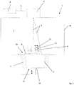
- Fig. 1 shows a schematic diagram of a device 1 according to an embodiment of the invention.
- the device 1 is used for the generative production of three-dimensional objects 2 by layer-wise selective solidification of solidifiable building material 3, namely a metal or plastic powder, by means of an energy beam 5 generated by a radiation generating device 4, namely a laser generating device, namely a laser beam.
- a radiation generating device 4 namely a laser generating device, namely a laser beam.
- the device 1 can be designed as a selective laser sintering device, for short SLS device, for performing selective laser sintering processes or as a selective laser melting device, for short SLM device, for performing selective laser melting processes.
- the radiation generating device 4 is assigned a beam deflecting device 6 for the targeted deflection of the energy beam 5 generated by the radiation generating device 4 onto a construction level 10 within a process chamber 7 of the device 1.
- the beam deflection device 6 comprises a number of suitable beam deflection elements (not shown), such as. B. Deflecting or deflecting mirrors. Since the radiation generating device 4 is a laser generating device, the beam deflecting device 6 can be referred to or viewed as a laser scanner, or scanner for short.
- the beam deflection device 6 is arranged in the beam path of the energy beam 5 generated by the radiation generating device 4.
- the device 1 comprises a coating device 8 for carrying out coating processes for applying a defined building material layer 9 of the solidifiable building material 3 on a building level 10, in which a selective solidification of the solidifiable building material 3 takes place, or on a building material layer previously applied as part of the implementation of a previous coating process 9.
- a building material layer 9 previously applied in the course of carrying out a previous coating process can also be referred to or regarded as building level 10, since a selective solidification of the solidifiable building material 3 also takes place in this level.
- the coating device 8 is, as indicated by the horizontally aligned double arrow, mounted so as to be movable relative to the building plane 10 and comprises one or more coating elements (not designated separately), that is to say, for example, coating blades.
- the device 1 further comprises a detection device 11 for detecting the quality, in particular the surface, of a layer of building material layer 9 applied by means of the coating device 8 in the context of carrying out a coating process, at least in sections qualitatively or quantitatively describing layer information.
- the acquisition device 11 is set up to acquire corresponding layer information during a coating process carried out by means of the coating device 8.
- the detection device 11 is arranged in the coating device 8. Because the detection device 11 is arranged in the coating device 8, the movement path of the detection device 11 is identical to the movement path of the coating device 8 in the context of a coating process.
- the acquisition device 11 is an image acquisition device, in particular a camera device, for acquiring the quality, in particular the surface, of layer image information that is applied at least in sections by means of the coating device 8 in the context of carrying out a coating process.
- the image acquisition device is a line camera, which is characterized by a comparatively high lateral resolution.
- the image acquisition device is therefore set up to receive corresponding slice image information one-dimensionally, i. H. in columns or rows.
- the focus of the image capturing device is of course aligned or adjusted to a building material layer (area) to be captured.
- the image capturing device is expediently provided with lighting means, i. H. z. B. a device for generating a flashlight, equipped for at least temporary illumination or illumination of a building material layer area to be detected.
- the detection device 11 By means of the detection device 11 it is possible to detect the quality, in particular the surface, of a building material layer 9 applied by means of the coating device 8 during a coating process.
- the quality of a building material layer 9 applied by means of the coating device 8 relates in particular to parameters such as smoothness, layer thickness, generally the order of the building material layer 9, in particular its surface.
- Layers of building material 9 applied by means of the coating device 8, which are to be recorded or recorded with regard to their quality, can also be already solidified building material layer (areas) and thus sections of the three-dimensional object 2 to be produced should be understood.
- Corresponding layer information can therefore also describe the quality of three-dimensional objects 2 or object surfaces, so that it is also possible to detect the quality of three-dimensional objects or object surfaces.
- the determination of the quality of corresponding building material layers 9 takes place in each case accompanied by corresponding coating processes or simultaneously with the implementation of corresponding coating processes for applying defined building material layers to a building level 10.
- the detection device 11 also enables (early) detection of impairments, i. E. H. Damage or defects to the coating device 8 are possible, since these are directly reflected in the building material layer 9 applied by means of the coating device 8 and can thus be described using corresponding layer information.
- impairments of a coating device 8 can be recognized by the fact that a defined distance between the applied building material layer 9 and the detection device 11 changes. This change in distance can, for. B. due to changes in focus of the detection device 11, affect the slice information and are therefore mapped via corresponding slice information.
- the acquisition device 11 embodied as an image acquisition device in the exemplary embodiments shown in the figures, corresponding changes in distance can cause changes in the resolution, the focus, the brightness, etc.
- the operation of the beam generating device 4 is controlled via a control device (not shown) assigned to the beam generating device 4.
- the control device is set up to generate control information controlling the operation of the beam generation device 4 and to communicate it to the beam generation device 4.
- Corresponding control information can contain irradiation information which, by means of the energy beam 5, describes regions to be selectively solidified, applied by means of the coating device 8, and / or beam properties, in particular energy densities, intensities, etc., of an energy beam 5 to be generated or generated.
- irradiation information which, by means of the energy beam 5, describes regions to be selectively solidified, applied by means of the coating device 8, and / or beam properties, in particular energy densities, intensities, etc., of an energy beam 5 to be generated or generated.
- the radiation generating device 4 can be operated in such a way that an energy beam 5 is generated after the completion of a coating process carried out by means of the coating device 8 (cf. Fig. 1 ).
- the solidification of the building material 3 only takes place after the coating process has ended, that is to say typically also after the corresponding layer information has been recorded.
- the energy beam 5 is directed via the beam deflection device 6 onto an area of a building material layer 9 applied by means of the coating device 8, for which the one detection device 11 has already acquired corresponding layer information.
- This is expedient as certain beam properties of the energy beam 5 can be adapted or set as a function of the quality of the applied building material layer 9 described by the layer information.
- irradiation of a building material layer 9 can also be omitted if the quality of the applied building material layer 9 does not meet certain specifiable or predefined quality criteria.
- user information can be output to a user via the control device, which shows a user a building material layer 9 which does not meet the corresponding quality criteria after a coating process has been carried out.
- the beam generating device 4 can be operated in such a way that an energy beam 5 is (still) generated during a coating process carried out by means of the coating device 8.
- the solidification of the building material 3 already takes place during the coating process, that is to say typically during the acquisition of the corresponding layer information.
- This variant enables a particular shortening of non-productive times as well as a particular acceleration of additive building processes, since coating, recording of corresponding layer information and irradiation can be carried out (essentially) simultaneously or at short intervals.
- the energy beam 5 is also directed via the beam deflection device 6 onto an area of a building material layer 9 applied by means of the coating device 8, for which the detection device 11 has already acquired corresponding layer information.
- the energy beam 5 is therefore tracked after the coating device 8 (cf. dashed illustration). This is useful as certain beam properties of the Energy beam 5 can be adapted or adjusted as a function of the quality of the applied building material layer 8 described by the layer information.
- irradiation of a building material layer 9 can also be omitted in this exemplary embodiment, provided that the quality of the applied building material layer 9 does not meet certain predeterminable or predetermined quality criteria.
- user information can be output to a user, which shows a user a building material layer 9 which does not meet the corresponding quality criteria after a coating process has been carried out.
- the or a further energy beam 5 is directed via the beam deflection device 6 onto an area of a building material layer 9 applied by means of the coating device 8, for which the detection device 11 has not yet recorded any corresponding layer information.
- the or a further energy beam 5 can therefore also be presented to the coating device 8 in advance.
- the device 1 additionally has a deflecting device 13 mounted movably relative to the construction level 10 for deflecting the protective gas flow flowing into the process chamber 7 into at least one may comprise a deflection direction different from a direction of inflow.
- the deflection device 13 is arranged on the coating device 8.
- the deflecting device 13 here comprises a plurality of deflecting elements connected to one another, by means of which a protective gas flow that circulates through the process chamber 7 can be generated.
- the cleaning device 12 is set up to use a fluid cleaning medium, d. H. z. B. a gas to flow onto or along at least one detection element to be cleaned.
- the device 1 naturally includes further functional components which are used to implement generative construction processes and thus for generative production three-dimensional objects 2 are required.
- these include, in particular, a housing device 14 with the process chamber 7, a support device 15 for carrying three-dimensional objects 2 to be produced or produced, the support device 15, as indicated by the vertically aligned double arrow, comprising a (vertically) movably mounted support element 16, a building material application and / or metering device (not shown) for applying and / or metering building material 3 into the process chamber 7.
- the device 1 can also have a further detection device for detecting, in particular the dimensions and / or the shape and / or the temperature, describing melting range information of a melted building material layer area ("melt pool") generated by means of the at least one energy beam 5. , as well as at least one evaluation device assigned to the further acquisition device for evaluating acquired melting range information with regard to a quality of the at least one three-dimensional object 2 to be produced. In this way, generative building processes can be monitored even better in the manner of a melt pool analysis and the quality of three-dimensional objects 2 to be produced can be better anticipated or calculated in advance.
- a further detection device for detecting, in particular the dimensions and / or the shape and / or the temperature, describing melting range information of a melted building material layer area ("melt pool") generated by means of the at least one energy beam 5.
- at least one evaluation device assigned to the further acquisition device for evaluating acquired melting range information with regard to a quality of the at least one three-dimensional object 2 to be produced.
- the device 1 can also include an interception device (not shown) for intercepting partially solidified and / or non-solidified building material 3 which, as a result of the construction process, is released from a building material layer 9 to be solidified and accelerated into the process chamber 7 in an uncontrolled manner.
- a corresponding interception device typically has a, z. B. slot-like, passage opening for the passage of the energy beam 5.
- a corresponding interception device can also be mounted so as to be movable relative to the building level 10.
- a method for the generative production of three-dimensional objects 2 can be implemented by layer-wise selective consolidation of a consolidatable building material 3 by means of an energy beam 5 generated by a radiation generator 4 for generating an energy beam 5 for consolidating a hardenable building material 3.
- the method is characterized in that, during a coating process carried out by means of a coating device 8, the quality, in particular the surface, of a layer of building material 9 applied in the course of the coating process describing layer information is recorded.
Claims (11)
- Dispositif (1) pour la fabrication générative d'au moins un objet tridimensionnel (2) par solidification sélective par couches d'au moins un matériau de construction solidifiable (3) au moyen d'au moins un faisceau d'énergie (5) généré par au moins un dispositif de génération de rayonnement (4), comprenant :- au moins un dispositif de génération de rayonnement (4) pour générer au moins un faisceau d'énergie (5) pour consolider au moins un matériau de construction (3) pouvant être consolidé,- au moins un dispositif de revêtement (8) pour l'exécution d'au moins une opération de revêtement pour l'application d'une couche de matériau de construction définie (9) d'au moins un matériau de construction (3) solidifiable sur un plan de construction (10) ou sur une couche de matériau de construction (9) d'au moins un matériau de construction (3) solidifiable appliquée auparavant dans le cadre de l'exécution d'une opération de revêtement précédente, dans lequel
l'au moins un dispositif de revêtement (8) est monté de manière mobile par rapport au plan de construction (19) et comprend un ou plusieurs éléments de revêtement qui sont déplacés sur le plan de construction (10) pour former des couches de matériau de construction définies, où- au moins un dispositif de détection (11) pour détecter des informations de couche décrivant au moins par sections la qualité, en particulier la surface, d'une couche de matériau de construction (9) appliquée au moyen du dispositif de revêtement (8) dans le cadre de la réalisation d'une opération de revêtement, le au moins un dispositif de détection (11) étant conçu à cet effet, saisir des informations de couche correspondantes pendant une opération de revêtement réalisée au moyen du dispositif de revêtement (8), le au moins un dispositif de saisie (11) étant monté mobile par rapport au plan de construction (10), le au moins un dispositif de saisie (11) étant couplé en mouvement avec le au moins un dispositif de revêtement (8) ; ainsi que- au moins un autre dispositif de détection (11) pour la détection d'informations de zone de fusion, décrivant en particulier les dimensions et/ou la forme et/ou la température, d'une zone de couche de matériau de construction fondue produite au moyen du au moins un faisceau d'énergie (5), ainsi qu'au moins un dispositif d'évaluation associé à l'autre dispositif de détection (11) pour l'évaluation d'informations de zone de fusion détectées en vue d'une qualité du au moins un objet tridimensionnel (2) à fabriquer ;caractérisé en ce que l'au moins un dispositif de détection (11) est intégré par construction dans l'au moins un dispositif de revêtement (8). - Dispositif selon la revendication 1, dans lequel l'au moins un dispositif de détection (11) est conçu comme un dispositif de détection d'images, en particulier un dispositif de caméra, pour détecter des informations d'image de couche décrivant au moins par sections la qualité, en particulier la surface, d'une couche de matériau de construction (9) d'au moins un matériau de construction (3) solidifiable appliquée au moyen du dispositif de revêtement (8) dans le cadre de la réalisation d'une opération de revêtement, ou comprend au moins un tel dispositif.
- Dispositif selon la revendication 2, dans lequel le dispositif d'acquisition d'images est conçu pour acquérir des informations d'image de couche correspondantes de manière unidimensionnelle ou pluridimensionnelle.
- Dispositif selon l'une quelconque des revendications précédentes, dans lequel ledit au moins un dispositif de génération de rayonnement (4) est adapté pour générer un faisceau d'énergie (5) pour solidifier ledit au moins un matériau de construction solidifiable (3) après la fin d'une opération de revêtement réalisée au moyen dudit dispositif de revêtement (8), ou
le au moins un dispositif de génération de rayonnement (4) est adapté pour générer un faisceau d'énergie (5) pour solidifier le au moins un matériau de construction solidifiable (3) pendant une opération de revêtement réalisée au moyen du dispositif de revêtement (8). - Dispositif selon la revendication 4, dans lequel l'au moins un dispositif de génération de rayonnement (4) est conçu pour générer un faisceau d'énergie (5) pour la solidification de l'au moins un matériau de construction solidifiable (3) après la fin d'un processus de revêtement réalisé au moyen du dispositif de revêtement (8), le faisceau d'énergie (5) pouvant être dirigé, en particulier par l'intermédiaire d'au moins un dispositif de déviation de faisceau (6), sur une zone d'une couche de matériau de construction (9) appliquée au moyen du dispositif de revêtement (8), pour laquelle l'au moins un dispositif de détection (11) a déjà détecté des informations de couche correspondantes, ou bien
le au moins un dispositif de génération de rayonnement (4) est conçu pour générer un faisceau d'énergie (5) pour la solidification du au moins un matériau de construction (3) solidifiable pendant une opération de revêtement réalisée au moyen du dispositif de revêtement (8), le faisceau d'énergie (5) étant généré, en particulier par l'intermédiaire d'au moins un dispositif de déviation de faisceau (6), sur une zone d'une couche de matériau de construction (9) appliquée au moyen du dispositif de revêtement (8), pour laquelle l'au moins un dispositif de détection (11) a déjà détecté des informations de couche correspondantes, ou sur une zone d'une couche de matériau de construction (9) appliquée au moyen du dispositif de revêtement (8), pour laquelle l'au moins un dispositif de détection (11) n'a pas encore détecté d'informations de couche correspondantes. - Dispositif selon l'une des revendications précédentes, comprenant en outre au moins un dispositif de commande pour commander le fonctionnement de l'au moins un dispositif de génération de faisceau (4), l'au moins un dispositif de commande étant conçu pour générer des informations de commande commandant le fonctionnement de l'au moins un dispositif de génération de faisceau (4) en fonction d'informations de couche détectées.
- Dispositif selon l'une des revendications précédentes, comprenant en outre au moins un dispositif de nettoyage (12) associé à l'au moins un dispositif de détection (11) pour éliminer les impuretés dues au processus de construction d'au moins un élément de détection, notamment optique, associé à l'au moins un dispositif de détection (11).
- Dispositif selon la revendication 7, dans lequel ledit au moins un dispositif de nettoyage (12) est agencé pour faire circuler un milieu de nettoyage fluide sur ou le long d'un élément de détection à nettoyer.
- Dispositif selon l'une des revendications précédentes, comprenant en outre au moins un dispositif de déviation, notamment monté mobile par rapport à un plan de construction (10), pour dévier un flux de gaz protecteur entrant dans une chambre de traitement (7) du dispositif (1) dans au moins une direction de déviation différente d'une direction d'entrée.
- Dispositif selon l'une des revendications précédentes, comprenant en outre au moins un dispositif d'interception pour intercepter le matériau de construction (3) partiellement consolidé et/ou non consolidé, qui se détache, en raison du processus de construction, d'une couche de matériau de construction (9) à consolider, appliquée au moyen du dispositif de revêtement (8), et qui est accéléré de manière incontrôlée dans une chambre de traitement (7) du dispositif (1).
- Procédé de fabrication générative d'au moins un objet tridimensionnel (2) par solidification sélective couche par couche d'au moins un matériau de construction solidifiable (3) au moyen d'au moins un faisceau d'énergie (5) généré par au moins un dispositif de génération de rayonnement (4) pour générer au moins un faisceau d'énergie (5) pour la solidification d'au moins un matériau de construction solidifiable (3) avec un dispositif (1) selon l'une des revendications précédentes, caractérisé en ce que, pendant un processus de fabrication au moyen d'un dispositif de revêtement (8), en particulier pour la réalisation d'au moins une opération de revêtement pour l'application d'une couche de matériau de construction (9) définie d'au moins un matériau de construction (3) solidifiable sur un plan de construction (10) ou sur une couche de matériau de construction (9) d'au moins un matériau de construction (3) solidifiable appliquée auparavant au moyen du dispositif de revêtement (8) dans le cadre de la réalisation d'une opération de revêtement précédente, des informations de couche décrivant la qualité, en particulier de la surface, d'une couche de matériau de construction (9) appliquée dans le cadre de l'opération de revêtement sont détectées, ainsi qu'une
l'enregistrement d'informations de zone de fusion, décrivant en particulier les dimensions et/ou la forme et/ou la température, d'une zone de couche de matériau de construction fondue produite au moyen du au moins un faisceau d'énergie (5), ainsi que l'évaluation d'informations de zone de fusion enregistrées en vue d'une qualité du au moins un objet tridimensionnel (2) à fabriquer.
Priority Applications (1)
| Application Number | Priority Date | Filing Date | Title |
|---|---|---|---|
| EP18186338.2A EP3441163B1 (fr) | 2015-06-25 | 2016-06-21 | Dispositif de fabrication additive d'au moins un objet tridimensionnel |
Applications Claiming Priority (2)
| Application Number | Priority Date | Filing Date | Title |
|---|---|---|---|
| DE102015110264.1A DE102015110264A1 (de) | 2015-06-25 | 2015-06-25 | Vorrichtung zur generativen Herstellung wenigstens eines dreidimensionalen Objekts |
| PCT/EP2016/064237 WO2016207123A1 (fr) | 2015-06-25 | 2016-06-21 | Dispositif de production générative d'au moins un objet tridimensionnel |
Related Child Applications (2)
| Application Number | Title | Priority Date | Filing Date |
|---|---|---|---|
| EP18186338.2A Division EP3441163B1 (fr) | 2015-06-25 | 2016-06-21 | Dispositif de fabrication additive d'au moins un objet tridimensionnel |
| EP18186338.2A Division-Into EP3441163B1 (fr) | 2015-06-25 | 2016-06-21 | Dispositif de fabrication additive d'au moins un objet tridimensionnel |
Publications (2)
| Publication Number | Publication Date |
|---|---|
| EP3313595A1 EP3313595A1 (fr) | 2018-05-02 |
| EP3313595B1 true EP3313595B1 (fr) | 2022-01-05 |
Family
ID=56178347
Family Applications (2)
| Application Number | Title | Priority Date | Filing Date |
|---|---|---|---|
| EP18186338.2A Active EP3441163B1 (fr) | 2015-06-25 | 2016-06-21 | Dispositif de fabrication additive d'au moins un objet tridimensionnel |
| EP16731125.7A Active EP3313595B1 (fr) | 2015-06-25 | 2016-06-21 | Dispositif de fabrication additive d'au moins un objet tridimensionnel |
Family Applications Before (1)
| Application Number | Title | Priority Date | Filing Date |
|---|---|---|---|
| EP18186338.2A Active EP3441163B1 (fr) | 2015-06-25 | 2016-06-21 | Dispositif de fabrication additive d'au moins un objet tridimensionnel |
Country Status (6)
| Country | Link |
|---|---|
| US (1) | US11911957B2 (fr) |
| EP (2) | EP3441163B1 (fr) |
| JP (2) | JP2018521217A (fr) |
| CN (1) | CN107548348A (fr) |
| DE (1) | DE102015110264A1 (fr) |
| WO (1) | WO2016207123A1 (fr) |
Families Citing this family (13)
| Publication number | Priority date | Publication date | Assignee | Title |
|---|---|---|---|---|
| DE102014112447A1 (de) * | 2014-08-29 | 2016-03-03 | Exone Gmbh | 3D-Drucker, 3D-Druckeranordnung und generatives Fertigungsverfahren |
| DE102016213609A1 (de) * | 2016-07-25 | 2018-01-25 | Eos Gmbh Electro Optical Systems | Verfahren und Vorrichtung zur Ermittlung der Bauteilqualität |
| DE102016113786A1 (de) * | 2016-07-27 | 2018-02-01 | Thyssenkrupp Ag | Verfahren zur Anstellwinkelverstellung eines Rotorblattes einer Windkraftanlage und Windkraftanlage |
| US11167454B2 (en) | 2017-01-13 | 2021-11-09 | General Electric Company | Method and apparatus for continuously refreshing a recoater blade for additive manufacturing |
| DE102017105819A1 (de) * | 2017-03-17 | 2018-09-20 | Cl Schutzrechtsverwaltungs Gmbh | Anlage zur additiven Herstellung dreidimensionaler Objekte |
| EP3473412A1 (fr) * | 2017-10-20 | 2019-04-24 | CL Schutzrechtsverwaltungs GmbH | Appareil et procédé de fabrication additive d'objets tridimensionnels |
| EP3486085A1 (fr) * | 2017-11-21 | 2019-05-22 | CL Schutzrechtsverwaltungs GmbH | Dispositif d'étalonnage pour un appareil de fabrication additive d'objets tridimensionnels |
| DE102017221909A1 (de) * | 2017-12-05 | 2019-06-06 | MTU Aero Engines AG | Schichtbauvorrichtung zur additiven Herstellung zumindest eines Bauteilbereichs eines Bauteils, Strömungsleiteinrichtung für eine Schichtbauvorrichtung und Verfahren zum Betreiben einer Schichtbauvorrichtung |
| CN109927296A (zh) * | 2017-12-15 | 2019-06-25 | 成都熠辉科技有限公司 | 一种用于3d打印的图像信息采集系统 |
| DE102018200566B4 (de) * | 2018-01-15 | 2021-07-15 | Fraunhofer-Gesellschaft zur Förderung der angewandten Forschung e.V. | System und Verfahren zur Überwachung der Fertigungsgenauigkeit bei der additiven Herstellung dreidimensionaler Bauteile |
| US11426818B2 (en) | 2018-08-10 | 2022-08-30 | The Research Foundation for the State University | Additive manufacturing processes and additively manufactured products |
| US11498283B2 (en) * | 2019-02-20 | 2022-11-15 | General Electric Company | Method and apparatus for build thickness control in additive manufacturing |
| CN117841365A (zh) * | 2024-03-06 | 2024-04-09 | 云耀深维(江苏)科技有限公司 | 增材制造中材料涂覆质量同步监测的系统和增材制造设备 |
Citations (3)
| Publication number | Priority date | Publication date | Assignee | Title |
|---|---|---|---|---|
| US20040173946A1 (en) * | 2003-03-07 | 2004-09-09 | Rolf Pfeifer | Process for quality control for a powder based layer building up process |
| DE102011009624A1 (de) * | 2011-01-28 | 2012-08-02 | Mtu Aero Engines Gmbh | Verfahren und Vorrichtung zur Prozessüberwachung |
| US20150165683A1 (en) * | 2013-12-13 | 2015-06-18 | General Electric Company | Operational performance assessment of additive manufacturing |
Family Cites Families (70)
| Publication number | Priority date | Publication date | Assignee | Title |
|---|---|---|---|---|
| KR910004219B1 (ko) * | 1987-12-10 | 1991-06-24 | 도오시바 기까이 가부시기가이샤 | 주형내의 가스제거상태를 검출하는 방법 및 장치 |
| US5045668A (en) * | 1990-04-12 | 1991-09-03 | Armco Inc. | Apparatus and method for automatically aligning a welding device for butt welding workpieces |
| US5632083A (en) * | 1993-08-05 | 1997-05-27 | Hitachi Construction Machinery Co., Ltd. | Lead frame fabricating method and lead frame fabricating apparatus |
| US5925268A (en) * | 1996-06-06 | 1999-07-20 | Engauge Inc. | Laser welding apparatus employing a tilting mechanism and seam follower |
| IT1290210B1 (it) * | 1997-01-29 | 1998-10-22 | Pirelli | Metodo per la produzione di pneumatici,per la realizzazione di stampi di vulcanizzazione per detti pneumatici,pneumatici e stampi cosi' |
| CA2227672A1 (fr) | 1997-01-29 | 1998-07-29 | Toyota Jidosha Kabushiki Kaisha | Methode et appareil de production d'un objet lamine |
| JP3235781B2 (ja) | 1997-02-06 | 2001-12-04 | トヨタ自動車株式会社 | 積層造形における散布方法及びその装置 |
| DE19749981A1 (de) * | 1997-11-12 | 1999-05-20 | Laser & Med Tech Gmbh | Verfahren und Vorrichtung zur Abtragung von Oberflächenverunreinigungen von metallischen, mineralischen, organischen Untergründen durch Einsatz eines Lasers |
| US6629831B2 (en) * | 1999-04-16 | 2003-10-07 | Coach Wei | Apparatus for altering the physical properties of fluids |
| JP2001034582A (ja) | 1999-05-17 | 2001-02-09 | Matsushita Electric Ind Co Ltd | コマンドパケットによってプロセッサを選択する並列処理装置及びそのシステム |
| SE521124C2 (sv) | 2000-04-27 | 2003-09-30 | Arcam Ab | Anordning samt metod för framställande av en tredimensionell produkt |
| US6979480B1 (en) * | 2000-06-09 | 2005-12-27 | 3M Innovative Properties Company | Porous inkjet receptor media |
| US6762502B1 (en) * | 2000-08-31 | 2004-07-13 | Micron Technology, Inc. | Semiconductor device packages including a plurality of layers substantially encapsulating leads thereof |
| EP1396556A1 (fr) * | 2002-09-06 | 2004-03-10 | ALSTOM (Switzerland) Ltd | Méthode pour controller la microstructure d'une couche dure fabriquée par revêtement utilisant un laser |
| US7754135B2 (en) * | 2003-02-25 | 2010-07-13 | Panasonic Electric Works Co., Ltd. | Three dimensional structure producing method and producing device |
| JP4431420B2 (ja) * | 2004-02-24 | 2010-03-17 | ヤマザキマザック株式会社 | 工作機械 |
| JP4390627B2 (ja) * | 2004-05-28 | 2009-12-24 | ヤマザキマザック株式会社 | レーザ焼き入れ工具 |
| US7556490B2 (en) * | 2004-07-30 | 2009-07-07 | Board Of Regents, The University Of Texas System | Multi-material stereolithography |
| FR2883503B1 (fr) * | 2005-03-23 | 2020-11-06 | Datacard Corp | Machine de marquage laser a haute cadence |
| JP4238938B2 (ja) | 2007-05-30 | 2009-03-18 | パナソニック電工株式会社 | 積層造形装置 |
| DE102007040755A1 (de) | 2007-08-28 | 2009-03-05 | Jens Jacob | Lasersintervorrichtung sowie Verfahren zum Herstellen von dreidimensionalen Objekten durch selektives Lasersintern |
| US7741578B2 (en) * | 2007-10-19 | 2010-06-22 | Honeywell International Inc. | Gas shielding structure for use in solid free form fabrication systems |
| JP4258567B1 (ja) | 2007-10-26 | 2009-04-30 | パナソニック電工株式会社 | 三次元形状造形物の製造方法 |
| JP2009123421A (ja) * | 2007-11-13 | 2009-06-04 | Canon Inc | 気密容器の製造方法 |
| DE102007056984A1 (de) * | 2007-11-27 | 2009-05-28 | Eos Gmbh Electro Optical Systems | Verfahren zum Herstellen eines dreidimensionalen Objekts mittels Lasersintern |
| US9561622B2 (en) * | 2008-05-05 | 2017-02-07 | Georgia Tech Research Corporation | Systems and methods for fabricating three-dimensional objects |
| JP5250338B2 (ja) | 2008-08-22 | 2013-07-31 | パナソニック株式会社 | 三次元形状造形物の製造方法、その製造装置および三次元形状造形物 |
| GB0816310D0 (en) * | 2008-09-05 | 2008-10-15 | Mtt Technologies Ltd | Filter assembly |
| WO2010043275A1 (fr) * | 2008-10-17 | 2010-04-22 | Huntsman Advanced Materials (Switzerland) Gmbh | Améliorations apportées à un appareil de prototypage rapide |
| US8345242B2 (en) * | 2008-10-28 | 2013-01-01 | Molecular Imprints, Inc. | Optical system for use in stage control |
| JP5243934B2 (ja) * | 2008-12-03 | 2013-07-24 | パナソニック株式会社 | 三次元形状造形物を造形する積層造形装置及び積層造形方法 |
| US8552337B2 (en) * | 2009-06-11 | 2013-10-08 | Illinois Tool Works Inc. | Weld defect detection systems and methods for laser hybrid welding |
| WO2011034985A1 (fr) * | 2009-09-17 | 2011-03-24 | Sciaky, Inc. | Fabrication de couche de faisceau d'électron |
| DE102009056687B4 (de) * | 2009-12-02 | 2011-11-10 | Prometal Rct Gmbh | Anlage zum schichtweisen Aufbau eines Formkörpers mit einer Beschichter-Reinigungsvorrichtung |
| CN102934026B (zh) * | 2009-12-17 | 2016-08-03 | 帝斯曼知识产权资产管理有限公司 | 用于加成法制造的可led固化的液体树脂组合物 |
| FR2954716B1 (fr) * | 2009-12-29 | 2012-02-10 | Plastic Omnium Cie | Procede de traitement surfacique de pieces de grandes dimensions, prehenseur de pieces adapte pour la mise en oeuvre d'un tel procede, utilisation de ce prehenseur et cabine de traitement |
| DE102010004036A1 (de) * | 2010-01-05 | 2011-07-07 | EOS GmbH Electro Optical Systems, 82152 | Vorrichtung zum generativen Herstellen eines dreidimensionalen Objekts mit kontinuierlicher Wärmezufuhr |
| DE102010041284A1 (de) | 2010-09-23 | 2012-03-29 | Siemens Aktiengesellschaft | Verfahren zum selektiven Lasersintern und für dieses Verfahren geeignete Anlage zum selektiven Lasersintern |
| US10124410B2 (en) * | 2010-09-25 | 2018-11-13 | Ipg Photonics Corporation | Methods and systems for coherent imaging and feedback control for modification of materials |
| DE102010052206B4 (de) * | 2010-11-10 | 2015-06-18 | Cl Schutzrechtsverwaltungs Gmbh | Vorrichtung zum Herstellen von dreidimensionalen Objekten |
| DE102011007957A1 (de) * | 2011-01-05 | 2012-07-05 | Voxeljet Technology Gmbh | Vorrichtung und Verfahren zum Aufbauen eines Schichtenkörpers mit wenigstens einem das Baufeld begrenzenden und hinsichtlich seiner Lage einstellbaren Körper |
| JP5950502B2 (ja) * | 2011-03-23 | 2016-07-13 | 株式会社ディスコ | ウエーハの分割方法 |
| DE102011111818A1 (de) * | 2011-08-27 | 2013-02-28 | Mtu Aero Engines Gmbh | Verfahren und Vorrichtung zur generativen Herstellung eines Bauteils |
| DE102011111498A1 (de) | 2011-08-31 | 2013-02-28 | Voxeljet Technology Gmbh | Vorrichtung zum schichtweisen Aufbau von Modellen |
| FR2984778B1 (fr) * | 2011-12-23 | 2014-09-12 | Michelin Soc Tech | Procede et appareil pour realiser des objets tridimensionnels |
| EP2797730B2 (fr) | 2011-12-28 | 2020-03-04 | Arcam Ab | Procédé et appareil de détection de défauts pour une fabrication de forme libre |
| DE102012004213A1 (de) * | 2012-03-06 | 2013-09-12 | Voxeljet Technology Gmbh | Verfahren und Vorrichtung zum Herstellen dreidimensionaler Modelle |
| US9868179B2 (en) * | 2012-03-09 | 2018-01-16 | TOYOKOH, Co., Ltd. | Laser irradiation device, laser irradiation system, and method for removing coating or adhering matter |
| JP6045589B2 (ja) * | 2012-07-27 | 2016-12-21 | 日産自動車株式会社 | カメラ装置、立体物検出装置及びレンズ洗浄方法 |
| WO2014074947A2 (fr) * | 2012-11-08 | 2014-05-15 | Das, Suman | Systèmes et procédés de fabrication additive et réparation de composants métalliques |
| WO2014095200A1 (fr) * | 2012-12-17 | 2014-06-26 | Arcam Ab | Procédé et appareil d'impression 3d |
| ES2670977T3 (es) | 2013-02-14 | 2018-06-04 | Renishaw Plc. | Aparato de solidificación selectiva por láser y método |
| US20140265048A1 (en) * | 2013-03-15 | 2014-09-18 | Matterfab Corp. | Cartridge for an additive manufacturing apparatus and method |
| US9659711B2 (en) * | 2013-05-31 | 2017-05-23 | Sabic Global Technologies B.V. | Capacitor films, methods of manufacture, and articles manufactured therefrom |
| DE102013213370A1 (de) * | 2013-07-09 | 2015-01-15 | MTU Aero Engines AG | Regelung bei generativer Fertigung |
| JP6341639B2 (ja) * | 2013-08-01 | 2018-06-13 | 株式会社ディスコ | 加工装置 |
| DE102013217598A1 (de) * | 2013-09-04 | 2015-03-05 | MTU Aero Engines AG | Vorrichtung zur Laser-Materialbearbeitung |
| FR3010334B1 (fr) | 2013-09-09 | 2015-09-25 | Michelin & Cie | Dispositif de depot de lit de poudre sur une surface muni d'une sonde a reponse electromagnetique, et procede correspondant |
| EP3046967A4 (fr) | 2013-09-16 | 2017-03-22 | Glanbia Nutritionals (Ireland) Plc | Procédé permettant d'inhiber la formation d'agrégats pendant l'hydrolyse de protéines |
| TWI596002B (zh) * | 2013-12-13 | 2017-08-21 | 三緯國際立體列印科技股份有限公司 | 立體列印裝置 |
| WO2015095531A1 (fr) * | 2013-12-20 | 2015-06-25 | Hexagon Metrology, Inc. | Appareil et procédé intégrés de mesure et de fabrication additive |
| US9789563B2 (en) * | 2013-12-20 | 2017-10-17 | Arcam Ab | Method for additive manufacturing |
| US9688027B2 (en) * | 2014-04-01 | 2017-06-27 | Stratasys, Inc. | Electrophotography-based additive manufacturing with overlay control |
| CN103949636B (zh) | 2014-05-05 | 2016-05-04 | 湖南华曙高科技有限责任公司 | 一种激光快速成型装置的快速成型方法 |
| MX355451B (es) * | 2014-06-20 | 2018-04-18 | Velo3D Inc | Aparatos, sistemas y metodos para impresion tridimensional. |
| CN105563823B (zh) * | 2014-11-11 | 2017-11-28 | 三纬国际立体列印科技股份有限公司 | 立体打印装置与立体打印方法 |
| US10048661B2 (en) * | 2014-12-17 | 2018-08-14 | General Electric Company | Visualization of additive manufacturing process data |
| US20160349215A1 (en) * | 2014-12-23 | 2016-12-01 | Edison Welding Institute, Inc. | Non-destructive evaluation of additive manufacturing components using an eddy current array system and method |
| US20180009170A1 (en) * | 2015-01-28 | 2018-01-11 | Hewlett-Packard Development Company, L.P. | Print dead zone identification |
| CN107214950B (zh) | 2017-07-19 | 2018-08-07 | 广州恒尚科技有限公司 | 自动调节3d打印机铺粉量装置及其方法 |
-
2015
- 2015-06-25 DE DE102015110264.1A patent/DE102015110264A1/de not_active Ceased
-
2016
- 2016-06-21 US US15/571,796 patent/US11911957B2/en active Active
- 2016-06-21 CN CN201680024394.1A patent/CN107548348A/zh active Pending
- 2016-06-21 JP JP2017558693A patent/JP2018521217A/ja active Pending
- 2016-06-21 EP EP18186338.2A patent/EP3441163B1/fr active Active
- 2016-06-21 EP EP16731125.7A patent/EP3313595B1/fr active Active
- 2016-06-21 WO PCT/EP2016/064237 patent/WO2016207123A1/fr active Application Filing
-
2019
- 2019-12-20 JP JP2019230101A patent/JP2020073719A/ja active Pending
Patent Citations (3)
| Publication number | Priority date | Publication date | Assignee | Title |
|---|---|---|---|---|
| US20040173946A1 (en) * | 2003-03-07 | 2004-09-09 | Rolf Pfeifer | Process for quality control for a powder based layer building up process |
| DE102011009624A1 (de) * | 2011-01-28 | 2012-08-02 | Mtu Aero Engines Gmbh | Verfahren und Vorrichtung zur Prozessüberwachung |
| US20150165683A1 (en) * | 2013-12-13 | 2015-06-18 | General Electric Company | Operational performance assessment of additive manufacturing |
Also Published As
| Publication number | Publication date |
|---|---|
| DE102015110264A1 (de) | 2016-12-29 |
| JP2020073719A (ja) | 2020-05-14 |
| US11911957B2 (en) | 2024-02-27 |
| EP3313595A1 (fr) | 2018-05-02 |
| EP3441163A1 (fr) | 2019-02-13 |
| EP3441163B1 (fr) | 2022-01-05 |
| WO2016207123A1 (fr) | 2016-12-29 |
| US20180215103A1 (en) | 2018-08-02 |
| JP2018521217A (ja) | 2018-08-02 |
| CN107548348A (zh) | 2018-01-05 |
Similar Documents
| Publication | Publication Date | Title |
|---|---|---|
| EP3313595B1 (fr) | Dispositif de fabrication additive d'au moins un objet tridimensionnel | |
| EP3390001B1 (fr) | Dispositif de fabrication additive d'un objet tridimensionnel et procédé correspondant | |
| EP3245043B1 (fr) | Dispositif de fabrication générative de pièces tridimensionnelles | |
| DE102014212246B3 (de) | Verfahren und Vorrichtung zur Qualitätssicherung | |
| EP3062991B1 (fr) | Procédé de fabrication d'un composant tridimensionnel | |
| DE102014208768B4 (de) | Verfahren und Vorrichtung zur Qualitätssicherung | |
| EP2942130B1 (fr) | Appareil et procédé pour la fabrication additive d'au moins une partie de composant | |
| EP3095591B1 (fr) | Procédé et dispositif destinés à une détermination au moins partielle d'un contour d'au moins une couche d' un objet fabriqué par un procédé additif | |
| DE102011009345B3 (de) | Verfahren und Vorrichtung zur Erfassung einer Partikeldichteverteilung im Strahl einer Düse | |
| WO2017157648A1 (fr) | Dispositif de production additive d'un objet tridimensionnel | |
| EP3377236B1 (fr) | Système de production additive d'au moins un objet tridimensionnel | |
| DE102014214939A1 (de) | Kamerabasierte Rauheitsbestimmung für generativ hergestellte Bauteile | |
| WO2017202818A1 (fr) | Procédé et dispositif de surveillance de processus lors de la fabrication additive de pièces | |
| DE102010046467A1 (de) | Vorrichtung zum Herstellen, Reparieren und/oder Austauschen eines Bauteils mittels eines durch Energiestrahlung verfestigbaren Pulvers, sowie ein Verfahren und ein gemäß dem Verfahren hergestellten Bauteils | |
| WO2021074188A1 (fr) | Procédé de fonctionnement d'un dispositif de fabrication additive d'un objet tridimensionnel et procédé de création d'une fenêtre de traitement pour mettre en œuvre ledit procédé | |
| DE102015107837A1 (de) | Vorrichtung zur generativen Herstellung wenigstens eines dreidimensionalen Objekts | |
| EP2929962A1 (fr) | Procédé et dispositif destinés à améliorer la qualité de matière première pour des procédés de fabrication génératifs | |
| DE102019116503A1 (de) | Verfahren und Vorrichtung zur Herstellung eines Multimaterialwerkstücks | |
| US20240140027A1 (en) | Apparatus for the additive manufacturing of at least one three-dimensional object | |
| EP3335856A1 (fr) | Dispositif d'exposition pour un dispositif de fabrication additive d'objets tridimensionnels | |
| EP3877153B1 (fr) | Procédé pour faire fonctionner un dispositif destiné à la fabrication additive d'un objet tridimensionnel | |
| DE102021128814A1 (de) | Vorrichtung zur generativen Herstellung eines dreidimensionalen Objekts | |
| DE102019206207A1 (de) | 3d-druckverfahren und 3d-druckvorrichtung | |
| DE102016211174A1 (de) | Verfahren und Vorrichtung zum additiven Herstellen zumindest eines Bauteilbereichs eines Bauteils |
Legal Events
| Date | Code | Title | Description |
|---|---|---|---|
| STAA | Information on the status of an ep patent application or granted ep patent |
Free format text: STATUS: THE INTERNATIONAL PUBLICATION HAS BEEN MADE |
|
| PUAI | Public reference made under article 153(3) epc to a published international application that has entered the european phase |
Free format text: ORIGINAL CODE: 0009012 |
|
| STAA | Information on the status of an ep patent application or granted ep patent |
Free format text: STATUS: REQUEST FOR EXAMINATION WAS MADE |
|
| 17P | Request for examination filed |
Effective date: 20170927 |
|
| AK | Designated contracting states |
Kind code of ref document: A1 Designated state(s): AL AT BE BG CH CY CZ DE DK EE ES FI FR GB GR HR HU IE IS IT LI LT LU LV MC MK MT NL NO PL PT RO RS SE SI SK SM TR |
|
| AX | Request for extension of the european patent |
Extension state: BA ME |
|
| RIN1 | Information on inventor provided before grant (corrected) |
Inventor name: BECHMANN, FLORIAN Inventor name: ZEULNER, FABIAN Inventor name: HERZOG, FRANK |
|
| DAV | Request for validation of the european patent (deleted) | ||
| DAX | Request for extension of the european patent (deleted) | ||
| STAA | Information on the status of an ep patent application or granted ep patent |
Free format text: STATUS: EXAMINATION IS IN PROGRESS |
|
| 17Q | First examination report despatched |
Effective date: 20181022 |
|
| STAA | Information on the status of an ep patent application or granted ep patent |
Free format text: STATUS: EXAMINATION IS IN PROGRESS |
|
| REG | Reference to a national code |
Ref country code: DE Ref legal event code: R079 Ref document number: 502016014356 Country of ref document: DE Free format text: PREVIOUS MAIN CLASS: B22F0003105000 Ipc: B22F0010280000 |
|
| RIC1 | Information provided on ipc code assigned before grant |
Ipc: B22F 10/28 20210101AFI20210609BHEP Ipc: B22F 10/36 20210101ALI20210609BHEP Ipc: B22F 10/37 20210101ALI20210609BHEP Ipc: B22F 12/60 20210101ALI20210609BHEP Ipc: B22F 12/90 20210101ALI20210609BHEP Ipc: B29C 64/153 20170101ALI20210609BHEP Ipc: B33Y 10/00 20150101ALI20210609BHEP Ipc: B33Y 30/00 20150101ALI20210609BHEP Ipc: B33Y 50/02 20150101ALI20210609BHEP Ipc: B22F 12/00 20210101ALI20210609BHEP Ipc: B22F 12/49 20210101ALN20210609BHEP |
|
| GRAP | Despatch of communication of intention to grant a patent |
Free format text: ORIGINAL CODE: EPIDOSNIGR1 |
|
| STAA | Information on the status of an ep patent application or granted ep patent |
Free format text: STATUS: GRANT OF PATENT IS INTENDED |
|
| INTG | Intention to grant announced |
Effective date: 20210716 |
|
| GRAS | Grant fee paid |
Free format text: ORIGINAL CODE: EPIDOSNIGR3 |
|
| GRAA | (expected) grant |
Free format text: ORIGINAL CODE: 0009210 |
|
| STAA | Information on the status of an ep patent application or granted ep patent |
Free format text: STATUS: THE PATENT HAS BEEN GRANTED |
|
| AK | Designated contracting states |
Kind code of ref document: B1 Designated state(s): AL AT BE BG CH CY CZ DE DK EE ES FI FR GB GR HR HU IE IS IT LI LT LU LV MC MK MT NL NO PL PT RO RS SE SI SK SM TR |
|
| REG | Reference to a national code |
Ref country code: GB Ref legal event code: FG4D Free format text: NOT ENGLISH |
|
| REG | Reference to a national code |
Ref country code: CH Ref legal event code: EP |
|
| REG | Reference to a national code |
Ref country code: AT Ref legal event code: REF Ref document number: 1460074 Country of ref document: AT Kind code of ref document: T Effective date: 20220115 |
|
| REG | Reference to a national code |
Ref country code: DE Ref legal event code: R096 Ref document number: 502016014356 Country of ref document: DE |
|
| REG | Reference to a national code |
Ref country code: IE Ref legal event code: FG4D Free format text: LANGUAGE OF EP DOCUMENT: GERMAN |
|
| REG | Reference to a national code |
Ref country code: LT Ref legal event code: MG9D |
|
| REG | Reference to a national code |
Ref country code: NL Ref legal event code: MP Effective date: 20220105 |
|
| PG25 | Lapsed in a contracting state [announced via postgrant information from national office to epo] |
Ref country code: NL Free format text: LAPSE BECAUSE OF FAILURE TO SUBMIT A TRANSLATION OF THE DESCRIPTION OR TO PAY THE FEE WITHIN THE PRESCRIBED TIME-LIMIT Effective date: 20220105 |
|
| PG25 | Lapsed in a contracting state [announced via postgrant information from national office to epo] |
Ref country code: SE Free format text: LAPSE BECAUSE OF FAILURE TO SUBMIT A TRANSLATION OF THE DESCRIPTION OR TO PAY THE FEE WITHIN THE PRESCRIBED TIME-LIMIT Effective date: 20220105 Ref country code: RS Free format text: LAPSE BECAUSE OF FAILURE TO SUBMIT A TRANSLATION OF THE DESCRIPTION OR TO PAY THE FEE WITHIN THE PRESCRIBED TIME-LIMIT Effective date: 20220105 Ref country code: PT Free format text: LAPSE BECAUSE OF FAILURE TO SUBMIT A TRANSLATION OF THE DESCRIPTION OR TO PAY THE FEE WITHIN THE PRESCRIBED TIME-LIMIT Effective date: 20220505 Ref country code: NO Free format text: LAPSE BECAUSE OF FAILURE TO SUBMIT A TRANSLATION OF THE DESCRIPTION OR TO PAY THE FEE WITHIN THE PRESCRIBED TIME-LIMIT Effective date: 20220405 Ref country code: LT Free format text: LAPSE BECAUSE OF FAILURE TO SUBMIT A TRANSLATION OF THE DESCRIPTION OR TO PAY THE FEE WITHIN THE PRESCRIBED TIME-LIMIT Effective date: 20220105 Ref country code: HR Free format text: LAPSE BECAUSE OF FAILURE TO SUBMIT A TRANSLATION OF THE DESCRIPTION OR TO PAY THE FEE WITHIN THE PRESCRIBED TIME-LIMIT Effective date: 20220105 Ref country code: ES Free format text: LAPSE BECAUSE OF FAILURE TO SUBMIT A TRANSLATION OF THE DESCRIPTION OR TO PAY THE FEE WITHIN THE PRESCRIBED TIME-LIMIT Effective date: 20220105 Ref country code: BG Free format text: LAPSE BECAUSE OF FAILURE TO SUBMIT A TRANSLATION OF THE DESCRIPTION OR TO PAY THE FEE WITHIN THE PRESCRIBED TIME-LIMIT Effective date: 20220405 |
|
| PG25 | Lapsed in a contracting state [announced via postgrant information from national office to epo] |
Ref country code: PL Free format text: LAPSE BECAUSE OF FAILURE TO SUBMIT A TRANSLATION OF THE DESCRIPTION OR TO PAY THE FEE WITHIN THE PRESCRIBED TIME-LIMIT Effective date: 20220105 Ref country code: LV Free format text: LAPSE BECAUSE OF FAILURE TO SUBMIT A TRANSLATION OF THE DESCRIPTION OR TO PAY THE FEE WITHIN THE PRESCRIBED TIME-LIMIT Effective date: 20220105 Ref country code: GR Free format text: LAPSE BECAUSE OF FAILURE TO SUBMIT A TRANSLATION OF THE DESCRIPTION OR TO PAY THE FEE WITHIN THE PRESCRIBED TIME-LIMIT Effective date: 20220406 Ref country code: FI Free format text: LAPSE BECAUSE OF FAILURE TO SUBMIT A TRANSLATION OF THE DESCRIPTION OR TO PAY THE FEE WITHIN THE PRESCRIBED TIME-LIMIT Effective date: 20220105 |
|
| PG25 | Lapsed in a contracting state [announced via postgrant information from national office to epo] |
Ref country code: IS Free format text: LAPSE BECAUSE OF FAILURE TO SUBMIT A TRANSLATION OF THE DESCRIPTION OR TO PAY THE FEE WITHIN THE PRESCRIBED TIME-LIMIT Effective date: 20220505 |
|
| REG | Reference to a national code |
Ref country code: DE Ref legal event code: R097 Ref document number: 502016014356 Country of ref document: DE |
|
| PG25 | Lapsed in a contracting state [announced via postgrant information from national office to epo] |
Ref country code: SM Free format text: LAPSE BECAUSE OF FAILURE TO SUBMIT A TRANSLATION OF THE DESCRIPTION OR TO PAY THE FEE WITHIN THE PRESCRIBED TIME-LIMIT Effective date: 20220105 Ref country code: SK Free format text: LAPSE BECAUSE OF FAILURE TO SUBMIT A TRANSLATION OF THE DESCRIPTION OR TO PAY THE FEE WITHIN THE PRESCRIBED TIME-LIMIT Effective date: 20220105 Ref country code: RO Free format text: LAPSE BECAUSE OF FAILURE TO SUBMIT A TRANSLATION OF THE DESCRIPTION OR TO PAY THE FEE WITHIN THE PRESCRIBED TIME-LIMIT Effective date: 20220105 Ref country code: EE Free format text: LAPSE BECAUSE OF FAILURE TO SUBMIT A TRANSLATION OF THE DESCRIPTION OR TO PAY THE FEE WITHIN THE PRESCRIBED TIME-LIMIT Effective date: 20220105 Ref country code: DK Free format text: LAPSE BECAUSE OF FAILURE TO SUBMIT A TRANSLATION OF THE DESCRIPTION OR TO PAY THE FEE WITHIN THE PRESCRIBED TIME-LIMIT Effective date: 20220105 Ref country code: CZ Free format text: LAPSE BECAUSE OF FAILURE TO SUBMIT A TRANSLATION OF THE DESCRIPTION OR TO PAY THE FEE WITHIN THE PRESCRIBED TIME-LIMIT Effective date: 20220105 |
|
| PLBE | No opposition filed within time limit |
Free format text: ORIGINAL CODE: 0009261 |
|
| STAA | Information on the status of an ep patent application or granted ep patent |
Free format text: STATUS: NO OPPOSITION FILED WITHIN TIME LIMIT |
|
| PG25 | Lapsed in a contracting state [announced via postgrant information from national office to epo] |
Ref country code: AL Free format text: LAPSE BECAUSE OF FAILURE TO SUBMIT A TRANSLATION OF THE DESCRIPTION OR TO PAY THE FEE WITHIN THE PRESCRIBED TIME-LIMIT Effective date: 20220105 |
|
| 26N | No opposition filed |
Effective date: 20221006 |
|
| PG25 | Lapsed in a contracting state [announced via postgrant information from national office to epo] |
Ref country code: MC Free format text: LAPSE BECAUSE OF FAILURE TO SUBMIT A TRANSLATION OF THE DESCRIPTION OR TO PAY THE FEE WITHIN THE PRESCRIBED TIME-LIMIT Effective date: 20220105 |
|
| REG | Reference to a national code |
Ref country code: CH Ref legal event code: PL |
|
| REG | Reference to a national code |
Ref country code: DE Ref legal event code: R081 Ref document number: 502016014356 Country of ref document: DE Owner name: CONCEPT LASER GMBH, DE Free format text: FORMER OWNER: CL SCHUTZRECHTSVERWALTUNGS GMBH, 96215 LICHTENFELS, DE |
|
| REG | Reference to a national code |
Ref country code: BE Ref legal event code: MM Effective date: 20220630 |
|
| PG25 | Lapsed in a contracting state [announced via postgrant information from national office to epo] |
Ref country code: SI Free format text: LAPSE BECAUSE OF FAILURE TO SUBMIT A TRANSLATION OF THE DESCRIPTION OR TO PAY THE FEE WITHIN THE PRESCRIBED TIME-LIMIT Effective date: 20220105 |
|
| PG25 | Lapsed in a contracting state [announced via postgrant information from national office to epo] |
Ref country code: LU Free format text: LAPSE BECAUSE OF NON-PAYMENT OF DUE FEES Effective date: 20220621 Ref country code: LI Free format text: LAPSE BECAUSE OF NON-PAYMENT OF DUE FEES Effective date: 20220630 Ref country code: IE Free format text: LAPSE BECAUSE OF NON-PAYMENT OF DUE FEES Effective date: 20220621 Ref country code: CH Free format text: LAPSE BECAUSE OF NON-PAYMENT OF DUE FEES Effective date: 20220630 |
|
| REG | Reference to a national code |
Ref country code: GB Ref legal event code: 732E Free format text: REGISTERED BETWEEN 20230406 AND 20230412 |
|
| PG25 | Lapsed in a contracting state [announced via postgrant information from national office to epo] |
Ref country code: BE Free format text: LAPSE BECAUSE OF NON-PAYMENT OF DUE FEES Effective date: 20220630 |
|
| P01 | Opt-out of the competence of the unified patent court (upc) registered |
Effective date: 20230517 |
|
| P02 | Opt-out of the competence of the unified patent court (upc) changed |
Effective date: 20230606 |
|
| PG25 | Lapsed in a contracting state [announced via postgrant information from national office to epo] |
Ref country code: IT Free format text: LAPSE BECAUSE OF FAILURE TO SUBMIT A TRANSLATION OF THE DESCRIPTION OR TO PAY THE FEE WITHIN THE PRESCRIBED TIME-LIMIT Effective date: 20220105 |
|
| PGFP | Annual fee paid to national office [announced via postgrant information from national office to epo] |
Ref country code: FR Payment date: 20230523 Year of fee payment: 8 Ref country code: DE Payment date: 20230523 Year of fee payment: 8 |
|
| REG | Reference to a national code |
Ref country code: AT Ref legal event code: MM01 Ref document number: 1460074 Country of ref document: AT Kind code of ref document: T Effective date: 20220621 |
|
| PG25 | Lapsed in a contracting state [announced via postgrant information from national office to epo] |
Ref country code: AT Free format text: LAPSE BECAUSE OF NON-PAYMENT OF DUE FEES Effective date: 20220621 |
|
| PGFP | Annual fee paid to national office [announced via postgrant information from national office to epo] |
Ref country code: GB Payment date: 20230523 Year of fee payment: 8 |
|
| PG25 | Lapsed in a contracting state [announced via postgrant information from national office to epo] |
Ref country code: HU Free format text: LAPSE BECAUSE OF FAILURE TO SUBMIT A TRANSLATION OF THE DESCRIPTION OR TO PAY THE FEE WITHIN THE PRESCRIBED TIME-LIMIT; INVALID AB INITIO Effective date: 20160621 |