EP3313595B1 - Apparatus for the additive manufacturing of at least one three-dimensional object - Google Patents
Apparatus for the additive manufacturing of at least one three-dimensional object Download PDFInfo
- Publication number
- EP3313595B1 EP3313595B1 EP16731125.7A EP16731125A EP3313595B1 EP 3313595 B1 EP3313595 B1 EP 3313595B1 EP 16731125 A EP16731125 A EP 16731125A EP 3313595 B1 EP3313595 B1 EP 3313595B1
- Authority
- EP
- European Patent Office
- Prior art keywords
- building material
- coating
- layer
- energy beam
- material layer
- Prior art date
- Legal status (The legal status is an assumption and is not a legal conclusion. Google has not performed a legal analysis and makes no representation as to the accuracy of the status listed.)
- Active
Links
- 238000004519 manufacturing process Methods 0.000 title claims description 18
- 239000000654 additive Substances 0.000 title description 2
- 230000000996 additive effect Effects 0.000 title description 2
- 238000000576 coating method Methods 0.000 claims description 166
- 239000004566 building material Substances 0.000 claims description 148
- 239000011248 coating agent Substances 0.000 claims description 104
- 238000001514 detection method Methods 0.000 claims description 71
- 238000000034 method Methods 0.000 claims description 60
- 230000005855 radiation Effects 0.000 claims description 25
- 238000010276 construction Methods 0.000 claims description 21
- 238000007711 solidification Methods 0.000 claims description 14
- 230000008023 solidification Effects 0.000 claims description 14
- 238000004140 cleaning Methods 0.000 claims description 13
- 230000001681 protective effect Effects 0.000 claims description 11
- 230000003287 optical effect Effects 0.000 claims description 9
- 238000002844 melting Methods 0.000 claims description 8
- 230000008018 melting Effects 0.000 claims description 8
- 239000004035 construction material Substances 0.000 claims description 4
- 238000011156 evaluation Methods 0.000 claims description 3
- 239000012530 fluid Substances 0.000 claims description 3
- 239000012535 impurity Substances 0.000 claims description 2
- 239000007789 gas Substances 0.000 description 13
- 238000007596 consolidation process Methods 0.000 description 5
- 230000006735 deficit Effects 0.000 description 5
- IJGRMHOSHXDMSA-UHFFFAOYSA-N Atomic nitrogen Chemical compound N#N IJGRMHOSHXDMSA-UHFFFAOYSA-N 0.000 description 4
- 238000000110 selective laser sintering Methods 0.000 description 4
- 239000002245 particle Substances 0.000 description 3
- 239000000843 powder Substances 0.000 description 3
- XKRFYHLGVUSROY-UHFFFAOYSA-N Argon Chemical compound [Ar] XKRFYHLGVUSROY-UHFFFAOYSA-N 0.000 description 2
- CURLTUGMZLYLDI-UHFFFAOYSA-N Carbon dioxide Chemical compound O=C=O CURLTUGMZLYLDI-UHFFFAOYSA-N 0.000 description 2
- 230000001133 acceleration Effects 0.000 description 2
- 238000004458 analytical method Methods 0.000 description 2
- 230000003466 anti-cipated effect Effects 0.000 description 2
- 238000011109 contamination Methods 0.000 description 2
- 230000007547 defect Effects 0.000 description 2
- 238000010586 diagram Methods 0.000 description 2
- 238000005286 illumination Methods 0.000 description 2
- 238000010309 melting process Methods 0.000 description 2
- 239000002184 metal Substances 0.000 description 2
- 239000000203 mixture Substances 0.000 description 2
- 229910052757 nitrogen Inorganic materials 0.000 description 2
- 238000004904 shortening Methods 0.000 description 2
- 229910052786 argon Inorganic materials 0.000 description 1
- 239000001569 carbon dioxide Substances 0.000 description 1
- 229910002092 carbon dioxide Inorganic materials 0.000 description 1
- 230000008878 coupling Effects 0.000 description 1
- 238000010168 coupling process Methods 0.000 description 1
- 238000005859 coupling reaction Methods 0.000 description 1
- 230000001419 dependent effect Effects 0.000 description 1
- 230000001066 destructive effect Effects 0.000 description 1
- 238000005516 engineering process Methods 0.000 description 1
- 230000010354 integration Effects 0.000 description 1
- 239000000463 material Substances 0.000 description 1
- 239000000155 melt Substances 0.000 description 1
- 230000008092 positive effect Effects 0.000 description 1
- 239000000779 smoke Substances 0.000 description 1
Images


Classifications
-
- B—PERFORMING OPERATIONS; TRANSPORTING
- B29—WORKING OF PLASTICS; WORKING OF SUBSTANCES IN A PLASTIC STATE IN GENERAL
- B29C—SHAPING OR JOINING OF PLASTICS; SHAPING OF MATERIAL IN A PLASTIC STATE, NOT OTHERWISE PROVIDED FOR; AFTER-TREATMENT OF THE SHAPED PRODUCTS, e.g. REPAIRING
- B29C64/00—Additive manufacturing, i.e. manufacturing of three-dimensional [3D] objects by additive deposition, additive agglomeration or additive layering, e.g. by 3D printing, stereolithography or selective laser sintering
- B29C64/10—Processes of additive manufacturing
- B29C64/141—Processes of additive manufacturing using only solid materials
- B29C64/153—Processes of additive manufacturing using only solid materials using layers of powder being selectively joined, e.g. by selective laser sintering or melting
-
- B—PERFORMING OPERATIONS; TRANSPORTING
- B22—CASTING; POWDER METALLURGY
- B22F—WORKING METALLIC POWDER; MANUFACTURE OF ARTICLES FROM METALLIC POWDER; MAKING METALLIC POWDER; APPARATUS OR DEVICES SPECIALLY ADAPTED FOR METALLIC POWDER
- B22F10/00—Additive manufacturing of workpieces or articles from metallic powder
- B22F10/20—Direct sintering or melting
- B22F10/28—Powder bed fusion, e.g. selective laser melting [SLM] or electron beam melting [EBM]
-
- B—PERFORMING OPERATIONS; TRANSPORTING
- B22—CASTING; POWDER METALLURGY
- B22F—WORKING METALLIC POWDER; MANUFACTURE OF ARTICLES FROM METALLIC POWDER; MAKING METALLIC POWDER; APPARATUS OR DEVICES SPECIALLY ADAPTED FOR METALLIC POWDER
- B22F10/00—Additive manufacturing of workpieces or articles from metallic powder
- B22F10/30—Process control
- B22F10/36—Process control of energy beam parameters
-
- B—PERFORMING OPERATIONS; TRANSPORTING
- B22—CASTING; POWDER METALLURGY
- B22F—WORKING METALLIC POWDER; MANUFACTURE OF ARTICLES FROM METALLIC POWDER; MAKING METALLIC POWDER; APPARATUS OR DEVICES SPECIALLY ADAPTED FOR METALLIC POWDER
- B22F10/00—Additive manufacturing of workpieces or articles from metallic powder
- B22F10/30—Process control
- B22F10/37—Process control of powder bed aspects, e.g. density
-
- B—PERFORMING OPERATIONS; TRANSPORTING
- B22—CASTING; POWDER METALLURGY
- B22F—WORKING METALLIC POWDER; MANUFACTURE OF ARTICLES FROM METALLIC POWDER; MAKING METALLIC POWDER; APPARATUS OR DEVICES SPECIALLY ADAPTED FOR METALLIC POWDER
- B22F12/00—Apparatus or devices specially adapted for additive manufacturing; Auxiliary means for additive manufacturing; Combinations of additive manufacturing apparatus or devices with other processing apparatus or devices
- B22F12/22—Driving means
- B22F12/222—Driving means for motion along a direction orthogonal to the plane of a layer
-
- B—PERFORMING OPERATIONS; TRANSPORTING
- B22—CASTING; POWDER METALLURGY
- B22F—WORKING METALLIC POWDER; MANUFACTURE OF ARTICLES FROM METALLIC POWDER; MAKING METALLIC POWDER; APPARATUS OR DEVICES SPECIALLY ADAPTED FOR METALLIC POWDER
- B22F12/00—Apparatus or devices specially adapted for additive manufacturing; Auxiliary means for additive manufacturing; Combinations of additive manufacturing apparatus or devices with other processing apparatus or devices
- B22F12/60—Planarisation devices; Compression devices
- B22F12/67—Blades
-
- B—PERFORMING OPERATIONS; TRANSPORTING
- B22—CASTING; POWDER METALLURGY
- B22F—WORKING METALLIC POWDER; MANUFACTURE OF ARTICLES FROM METALLIC POWDER; MAKING METALLIC POWDER; APPARATUS OR DEVICES SPECIALLY ADAPTED FOR METALLIC POWDER
- B22F12/00—Apparatus or devices specially adapted for additive manufacturing; Auxiliary means for additive manufacturing; Combinations of additive manufacturing apparatus or devices with other processing apparatus or devices
- B22F12/90—Means for process control, e.g. cameras or sensors
-
- B—PERFORMING OPERATIONS; TRANSPORTING
- B23—MACHINE TOOLS; METAL-WORKING NOT OTHERWISE PROVIDED FOR
- B23K—SOLDERING OR UNSOLDERING; WELDING; CLADDING OR PLATING BY SOLDERING OR WELDING; CUTTING BY APPLYING HEAT LOCALLY, e.g. FLAME CUTTING; WORKING BY LASER BEAM
- B23K26/00—Working by laser beam, e.g. welding, cutting or boring
- B23K26/0093—Working by laser beam, e.g. welding, cutting or boring combined with mechanical machining or metal-working covered by other subclasses than B23K
-
- B—PERFORMING OPERATIONS; TRANSPORTING
- B23—MACHINE TOOLS; METAL-WORKING NOT OTHERWISE PROVIDED FOR
- B23K—SOLDERING OR UNSOLDERING; WELDING; CLADDING OR PLATING BY SOLDERING OR WELDING; CUTTING BY APPLYING HEAT LOCALLY, e.g. FLAME CUTTING; WORKING BY LASER BEAM
- B23K26/00—Working by laser beam, e.g. welding, cutting or boring
- B23K26/02—Positioning or observing the workpiece, e.g. with respect to the point of impact; Aligning, aiming or focusing the laser beam
- B23K26/03—Observing, e.g. monitoring, the workpiece
- B23K26/032—Observing, e.g. monitoring, the workpiece using optical means
-
- B—PERFORMING OPERATIONS; TRANSPORTING
- B23—MACHINE TOOLS; METAL-WORKING NOT OTHERWISE PROVIDED FOR
- B23K—SOLDERING OR UNSOLDERING; WELDING; CLADDING OR PLATING BY SOLDERING OR WELDING; CUTTING BY APPLYING HEAT LOCALLY, e.g. FLAME CUTTING; WORKING BY LASER BEAM
- B23K26/00—Working by laser beam, e.g. welding, cutting or boring
- B23K26/16—Removal of by-products, e.g. particles or vapours produced during treatment of a workpiece
-
- B—PERFORMING OPERATIONS; TRANSPORTING
- B23—MACHINE TOOLS; METAL-WORKING NOT OTHERWISE PROVIDED FOR
- B23K—SOLDERING OR UNSOLDERING; WELDING; CLADDING OR PLATING BY SOLDERING OR WELDING; CUTTING BY APPLYING HEAT LOCALLY, e.g. FLAME CUTTING; WORKING BY LASER BEAM
- B23K26/00—Working by laser beam, e.g. welding, cutting or boring
- B23K26/34—Laser welding for purposes other than joining
- B23K26/342—Build-up welding
-
- B—PERFORMING OPERATIONS; TRANSPORTING
- B29—WORKING OF PLASTICS; WORKING OF SUBSTANCES IN A PLASTIC STATE IN GENERAL
- B29C—SHAPING OR JOINING OF PLASTICS; SHAPING OF MATERIAL IN A PLASTIC STATE, NOT OTHERWISE PROVIDED FOR; AFTER-TREATMENT OF THE SHAPED PRODUCTS, e.g. REPAIRING
- B29C64/00—Additive manufacturing, i.e. manufacturing of three-dimensional [3D] objects by additive deposition, additive agglomeration or additive layering, e.g. by 3D printing, stereolithography or selective laser sintering
- B29C64/30—Auxiliary operations or equipment
- B29C64/35—Cleaning
-
- B—PERFORMING OPERATIONS; TRANSPORTING
- B29—WORKING OF PLASTICS; WORKING OF SUBSTANCES IN A PLASTIC STATE IN GENERAL
- B29C—SHAPING OR JOINING OF PLASTICS; SHAPING OF MATERIAL IN A PLASTIC STATE, NOT OTHERWISE PROVIDED FOR; AFTER-TREATMENT OF THE SHAPED PRODUCTS, e.g. REPAIRING
- B29C64/00—Additive manufacturing, i.e. manufacturing of three-dimensional [3D] objects by additive deposition, additive agglomeration or additive layering, e.g. by 3D printing, stereolithography or selective laser sintering
- B29C64/30—Auxiliary operations or equipment
- B29C64/386—Data acquisition or data processing for additive manufacturing
- B29C64/393—Data acquisition or data processing for additive manufacturing for controlling or regulating additive manufacturing processes
-
- B—PERFORMING OPERATIONS; TRANSPORTING
- B33—ADDITIVE MANUFACTURING TECHNOLOGY
- B33Y—ADDITIVE MANUFACTURING, i.e. MANUFACTURING OF THREE-DIMENSIONAL [3-D] OBJECTS BY ADDITIVE DEPOSITION, ADDITIVE AGGLOMERATION OR ADDITIVE LAYERING, e.g. BY 3-D PRINTING, STEREOLITHOGRAPHY OR SELECTIVE LASER SINTERING
- B33Y10/00—Processes of additive manufacturing
-
- B—PERFORMING OPERATIONS; TRANSPORTING
- B33—ADDITIVE MANUFACTURING TECHNOLOGY
- B33Y—ADDITIVE MANUFACTURING, i.e. MANUFACTURING OF THREE-DIMENSIONAL [3-D] OBJECTS BY ADDITIVE DEPOSITION, ADDITIVE AGGLOMERATION OR ADDITIVE LAYERING, e.g. BY 3-D PRINTING, STEREOLITHOGRAPHY OR SELECTIVE LASER SINTERING
- B33Y30/00—Apparatus for additive manufacturing; Details thereof or accessories therefor
-
- B—PERFORMING OPERATIONS; TRANSPORTING
- B33—ADDITIVE MANUFACTURING TECHNOLOGY
- B33Y—ADDITIVE MANUFACTURING, i.e. MANUFACTURING OF THREE-DIMENSIONAL [3-D] OBJECTS BY ADDITIVE DEPOSITION, ADDITIVE AGGLOMERATION OR ADDITIVE LAYERING, e.g. BY 3-D PRINTING, STEREOLITHOGRAPHY OR SELECTIVE LASER SINTERING
- B33Y40/00—Auxiliary operations or equipment, e.g. for material handling
-
- B—PERFORMING OPERATIONS; TRANSPORTING
- B33—ADDITIVE MANUFACTURING TECHNOLOGY
- B33Y—ADDITIVE MANUFACTURING, i.e. MANUFACTURING OF THREE-DIMENSIONAL [3-D] OBJECTS BY ADDITIVE DEPOSITION, ADDITIVE AGGLOMERATION OR ADDITIVE LAYERING, e.g. BY 3-D PRINTING, STEREOLITHOGRAPHY OR SELECTIVE LASER SINTERING
- B33Y50/00—Data acquisition or data processing for additive manufacturing
- B33Y50/02—Data acquisition or data processing for additive manufacturing for controlling or regulating additive manufacturing processes
-
- B—PERFORMING OPERATIONS; TRANSPORTING
- B22—CASTING; POWDER METALLURGY
- B22F—WORKING METALLIC POWDER; MANUFACTURE OF ARTICLES FROM METALLIC POWDER; MAKING METALLIC POWDER; APPARATUS OR DEVICES SPECIALLY ADAPTED FOR METALLIC POWDER
- B22F12/00—Apparatus or devices specially adapted for additive manufacturing; Auxiliary means for additive manufacturing; Combinations of additive manufacturing apparatus or devices with other processing apparatus or devices
- B22F12/40—Radiation means
- B22F12/49—Scanners
-
- B—PERFORMING OPERATIONS; TRANSPORTING
- B22—CASTING; POWDER METALLURGY
- B22F—WORKING METALLIC POWDER; MANUFACTURE OF ARTICLES FROM METALLIC POWDER; MAKING METALLIC POWDER; APPARATUS OR DEVICES SPECIALLY ADAPTED FOR METALLIC POWDER
- B22F2999/00—Aspects linked to processes or compositions used in powder metallurgy
-
- Y—GENERAL TAGGING OF NEW TECHNOLOGICAL DEVELOPMENTS; GENERAL TAGGING OF CROSS-SECTIONAL TECHNOLOGIES SPANNING OVER SEVERAL SECTIONS OF THE IPC; TECHNICAL SUBJECTS COVERED BY FORMER USPC CROSS-REFERENCE ART COLLECTIONS [XRACs] AND DIGESTS
- Y02—TECHNOLOGIES OR APPLICATIONS FOR MITIGATION OR ADAPTATION AGAINST CLIMATE CHANGE
- Y02P—CLIMATE CHANGE MITIGATION TECHNOLOGIES IN THE PRODUCTION OR PROCESSING OF GOODS
- Y02P10/00—Technologies related to metal processing
- Y02P10/25—Process efficiency
Definitions
- the invention relates to a device for the generative production of at least one three-dimensional object by layer-wise selective solidification of at least one solidifiable building material by means of at least one energy beam generated by at least one radiation generating device.
- Such devices are basically known for the generative production of three-dimensional objects with different cross-sectional geometries.
- Three-dimensional objects to be produced are built up successively by layer-by-layer selective consolidation of a consolidatable building material in corresponding cross-sectional areas of the objects to be produced by means of an energy beam generated by a radiation generator.
- Corresponding devices include, inter alia, a beam generating device for generating an energy beam for solidifying a solidifiable building material and a coating device for carrying out a coating process for applying a defined building material layer of the solidifiable building material on a building level or on a building material layer previously applied in the course of carrying out a previous coating process.
- the pamphlets US 2015/165683 A1 and US 2004/173946 A1 relate to a device for the generative production of at least one three-dimensional object according to the preamble of claim 1 of the present invention.
- the invention is based on the object of specifying a device for the generative production of at least one three-dimensional object which is improved in comparison.
- the device described herein is used for the generative production of at least one three-dimensional object by layer-wise selective solidification of at least one solidifiable building material by means of at least one energy beam generated by at least one radiation generating device.
- a correspondingly solidifiable building material is typically powdery or powdery. The building material can therefore be z.
- a corresponding radiation generating device can be a laser generating device for generating a laser beam, or a laser for short, or the radiation generating device can comprise at least one such device.
- the device can e.g. B. be designed as a selective laser sintering device, SLS device for short, for performing selective laser sintering processes or as a selective laser melting device, SLM device for short, for performing selective laser melting processes.
- a corresponding radiation generating device can also be a particle generating device for generating particle radiation, or the radiation generating device can include at least one such device.
- the device comprises in a manner known per se at least one coating device for carrying out at least one coating process for applying a defined building material layer of the at least one solidifiable building material on a building level in which a selective solidification of the solidifiable building material takes place, or on one in the context of carrying out a previous coating process previously applied building material layer.
- a building material layer previously applied in the course of carrying out a previous coating process can therefore also be referred to or regarded as a building level, since solidification of a solidifiable building material also takes place in this level.
- a corresponding coating device comprises one or more coating elements, that is to say, for example, coating blades, which are moved over a building plane in order to form defined layers of building material.
- a coating device is accordingly mounted so as to be movable relative to a building plane.
- the device further comprises at least one detection device for detecting the quality, in particular the surface, of a layer information that describes at least sections of the building material layer applied by means of the coating device in the course of carrying out a coating process.
- the at least one detection device is set up to detect corresponding layer information during a coating process carried out by means of the coating device. By means of a corresponding detection device, it is therefore possible to detect the quality, in particular of the surface, of a layer of building material applied by means of the coating device during a coating process carried out by means of the coating device.
- the acquisition device acquires corresponding layer information which, at least in sections, qualitatively or quantitatively describes the quality, in particular the surface, of a building material layer applied by means of the coating device in the course of carrying out a coating process.
- the quality of a building material layer applied by means of the coating device relates in particular to parameters such as smoothness, layer thickness, generally the order of the building material layer or its surface.
- Building material layers that are to be detected or detected with regard to their quality and applied by means of the coating device can also be understood to mean already solidified building material layer (areas) and thus sections of a three-dimensional object to be produced.
- Corresponding layer information can therefore also describe the quality of three-dimensional objects or object surfaces, so that the quality of three-dimensional objects or object surfaces can also be recorded.
- B. can be useful in the production of hybrid components to record or create space-related contours.
- the determination of the quality of corresponding building material layers can in any case go hand in hand with corresponding coating processes; the determination of the quality of corresponding layers of building material is therefore carried out simultaneously with the implementation of corresponding coating processes for applying defined layers of building material to a building level. In this way, non-productive times can be reduced and generative construction processes can be accelerated overall. In comparison to the prior art described at the beginning, it is not necessary to wait for the completion of the implementation of a coating process in order to determine the quality of a respective one applied in the course of the coating process To capture building material layer.
- the detection of the quality, in particular the surface, of the corresponding layers of building material also does not necessarily require operating personnel, which has a positive effect on the process management in terms of production or process technology and thus also in economic terms.
- the detection device can also be used to (early) detect impairments, i. H. Damage or defects to a coating device are possible, since these are directly reflected in the layer of building material applied by means of the coating device and can thus be described using corresponding layer information.
- impairments of a coating device can be recognized by the fact that a defined distance between the applied building material layer and the detection device changes. This change in distance can affect the slice information and can therefore be mapped using corresponding slice information.
- a capturing device designed as an image capturing device as explained below, or a capturing device comprising such a device, corresponding changes in distance may result in changes in resolution, brightness, etc.
- a corresponding acquisition device can in particular be designed as an image acquisition device, in particular a camera device, for acquiring the quality, in particular the surface, of a layer image information that is applied at least in sections by means of the coating device in the context of carrying out a coating process, or includes at least one such layer image information.
- Corresponding image capturing devices can, for. B. be designed as a CCD camera or comprise a CCD or other optical sensors. The focus of corresponding image recording or camera devices is of course aligned or set on a building material layer (area) to be recorded.
- a corresponding image capturing device can be equipped with lighting means for at least temporarily illuminating or illuminating a building material layer area to be captured.
- lighting means for at least temporarily illuminating or illuminating a building material layer area to be captured.
- appropriate lighting means in particular in the case of a camera device, e.g. B. be a device for generating a flashlight.
- a corresponding image acquisition device can be set up to acquire corresponding slice image information in one dimension, ie in columns or rows, or in multiple dimensions.
- An image acquisition device can therefore be a line camera, which can be viewed through a comparatively high lateral resolution. In this context, resolutions of 1600 dpi or more are conceivable.
- this provides an improved device for the generative production of at least one three-dimensional object.
- the device naturally includes further functional components which are typically required for the implementation of generative construction processes and thus for the generative production of three-dimensional objects.
- Functional components of the device are generally to be understood as components or component groups which are typically directly related to a generative construction process.
- An inert protective gas atmosphere typically prevails in a corresponding process chamber, i. H. the process chamber is typically covered with an inert protective gas, e.g. B. argon, nitrogen, etc., filled or is flowed through by such.
- a corresponding detection device is movably mounted relative to a building plane (to be coated) or an applied building material layer.
- the detection device is thus tracked to a movement of a coating device mounted movably relative to a building plane (to be coated) or an applied building material layer in the course of carrying out a coating process.
- the movement path of the detection device is identical to the movement path of the coating device in the context of a coating process.
- a corresponding detection device is coupled to a coating device movably mounted relative to a building plane (to be coated) or an applied building material layer.
- the detection device is thus moved along with a movement of the coating device in the context of carrying out a coating process or follows the movement of the coating device.
- the movement path of the detection device is identical to the movement path of a coating device in the context of a coating process.
- a corresponding movement coupling of a corresponding detection device with a corresponding coating device is implemented in that the detection device is arranged or formed at least in sections in the coating device.
- An arrangement of a detection device in a coating device typically includes a material and / or non-positive and / or form-fitting, possibly detachable (damage-free or non-destructive) structural connection between the detection device and the coating device.
- An embodiment of a detection device in a coating device includes, according to the invention, a structural integration of the detection device into the coating device.
- an energy beam can be generated and solidified building material can be solidified by means of the generated energy beam either after the completion of a coating process or already during a coating process.
- the operation of the at least one beam generating device is controlled via a control device assigned to the beam generating device.
- the control device is set up to generate control information that controls the operation of the at least one beam generation device and to communicate it to the beam generation device.
- a corresponding radiation generating device can be set up accordingly to generate an energy beam for solidifying a solidifiable To produce building material after completion of a coating process carried out by means of the coating device.
- the solidification of the building material only takes place after the coating process has been completed, i. H. typically even after the relevant shift information has been recorded.
- the energy beam can be steered, in particular via at least one beam deflection device, onto an area of an applied building material layer, for which the at least one detection device has already acquired corresponding layer information. This is useful as certain beam properties of the energy beam can be adapted or set as a function of the quality of the applied building material layer described by the layer information.
- irradiation of a building material layer can also be omitted if the quality of the applied building material layer does not meet certain predefinable or predetermined quality criteria.
- user information can be output to a user, which shows a user a building material layer that does not meet the corresponding quality criteria after a coating process has been carried out.
- a corresponding beam generating device can be set up to generate an energy beam for solidifying the at least one solidifiable building material (still) during a coating process carried out by means of the coating device.
- the solidification of the building material already takes place during the coating process, i.e. H. typically during the acquisition of the relevant shift information.
- This variant enables a particular shortening of non-productive times as well as a particular acceleration of generative construction processes, since coating, recording of the corresponding layer information and irradiation can be carried out (essentially) simultaneously or at short intervals.
- the energy beam can also be steered, in particular via at least one beam deflection device, onto a region of a layer of building material applied by means of the coating device, for which the at least one detection device has already acquired corresponding layer information.
- the energy beam can therefore be tracked after the coating device.
- this is expedient as certain beam properties of the energy beam can be adapted or set here as a function of the quality of the applied building material layer described by the layer information.
- irradiation of a building material layer can also be omitted if the quality of the applied building material layer does not meet certain predefinable or predetermined quality criteria.
- user information can be output to a user indicating a building material layer that does not meet a corresponding quality criteria for a user Implementation of a coating process indicates.
- the or a further energy beam can be steered, in particular via at least one beam deflection device, onto an area of a building material layer applied by means of the coating device, for which the at least one detection device has not yet recorded any corresponding layer information.
- the or a further energy beam can therefore be presented in advance to the coating device.
- An energy beam preceding the coating device and one following the coating device can differ in their beam properties, in particular their energy density, intensity, etc.;
- an energy beam leading to the coating device can cause pre-consolidation of the building material to be consolidated and an energy beam following the coating device can cause post-consolidation of the pre-consolidated building material.
- the device can comprise at least one control device for controlling the operation of the at least one beam generating device.
- the control device can be set up to generate control information controlling the operation of the at least one beam generating device as a function of the acquired slice information.
- Corresponding control information can contain irradiation information which, by means of the energy beam, describes regions to be selectively solidified, applied by means of the coating device, and / or beam properties, in particular energy densities, intensities, etc., of an energy beam to be generated or generated.
- irradiation of a building material layer can optionally also be omitted (in certain areas or locally) if the quality of the applied building material layer (in certain areas or locally) does not meet certain predeterminable or predetermined quality criteria.
- a corresponding detection device or, respectively, this associated, in particular optical, detection elements can be used depending on the construction process, e.g. B. be contaminated by deposits of fine building material and / or smoke particles.
- the detection device can therefore have at least one cleaning device for removing construction process-related contamination of at least one of the at least one detection device associated, in particular optical, detection element, e.g. B. an optical lens assigned.
- a corresponding cleaning device can be set up to flow a fluid cleaning medium onto or along at least one detection element to be cleaned.
- a corresponding cleaning medium can be a gas, ie carbon dioxide, nitrogen, etc., for example.
- a gas used as a cleaning medium can also be an inert protective gas, which flows into a device-side process chamber.
- the device can comprise at least one deflection device, in particular movably mounted relative to a building plane, for deflecting a protective gas flow flowing into a process chamber of the device in at least one deflection direction different from a flow direction.
- a corresponding deflection device can comprise a plurality of deflection elements arranged or formed within a process chamber.
- a protective gas flow that circulates in a circular manner through a process chamber can be generated by suitable arrangement and alignment of corresponding deflecting elements.
- the device can also have at least one further detection device for detecting, in particular the dimensions and / or the shape and / or the temperature, describing melting range information of a melted building material layer area ("melt pool") generated by means of the at least one energy beam, as well as at least one evaluation device assigned to the further detection device for evaluating acquired melting range information with regard to a quality of the at least one three-dimensional object to be produced.
- at least one further detection device for detecting, in particular the dimensions and / or the shape and / or the temperature, describing melting range information of a melted building material layer area ("melt pool") generated by means of the at least one energy beam
- at least one evaluation device assigned to the further detection device for evaluating acquired melting range information with regard to a quality of the at least one three-dimensional object to be produced.
- the device can also include at least one interception device for intercepting partially solidified and / or non-solidified building material which, as a result of the construction process, detaches itself from a building material layer to be solidified and is accelerated in an uncontrolled manner into a device-side process chamber.
- at least one interception device for intercepting partially solidified and / or non-solidified building material which, as a result of the construction process, detaches itself from a building material layer to be solidified and is accelerated in an uncontrolled manner into a device-side process chamber.
- a corresponding interception device typically has at least one, e.g. B. slot-like, passage opening for the passage of an energy beam.
- a corresponding interception device can also be mounted so as to be movable relative to a building plane.
- the invention also relates to a method for the generative production of at least one three-dimensional object by layer-wise selective solidification of at least one solidifiable building material by means of at least one of at least one radiation generating device for generating at least one energy beam for solidifying at least one solidifiable building material generated energy beam, in particular with a device as described above.
- the method is characterized in that, during a coating process carried out by means of a coating device, the quality, in particular of the surface, of a layer information describing the building material layer applied in the course of the coating process is recorded.
- At least one detection device mounted movably relative to a building level (to be coated) or an applied building material layer is used. It is also according to the invention to use at least one coating device for performing at least one coating process for applying a defined building material layer of at least one solidifiable building material on a building level or on a building material layer of at least one solidifiable building material previously applied by means of the coating device in the context of performing a previous coating procedure, which relatively is mounted movable to a building level.
- the at least one detection device is coupled in terms of movement to the at least one coating device.
- At least one detection device can be used which is designed as an image detection device, in particular a camera device, for detecting the quality, in particular the surface, of a layer image information applied at least in sections by means of the coating device in the context of carrying out a coating process, or at least includes such.
- an energy beam to solidify the at least A solidifiable building material can be generated after the acquisition of corresponding layer information has ended after a coating process carried out by means of the coating device has been completed.
- the energy beam can be directed, in particular via at least one beam deflection device, onto a region of a layer of building material applied by means of the coating device, for which the at least one detection device has already acquired corresponding layer information.
- an energy beam for solidifying the at least one solidifiable building material can (still) be generated during the acquisition of corresponding layer information during a coating process carried out by means of the coating device.
- the energy beam can be directed, in particular via at least one beam deflection device, onto an area of a building material layer applied by means of the coating device, for which the at least one detection device has already acquired corresponding layer information, or directed onto an area of a building material layer applied by means of the coating device, to which the at least one acquisition device has not yet acquired any corresponding slice information.
- the operation of the at least one beam generating device can be controlled via at least one control device for controlling the operation of the at least one beam generating device, the control device generating control information controlling the operation of the at least one beam generating device as a function of the acquired layer information.
- construction process-related contamination of at least one of the at least one detection device, in particular optical, detection element can be removed by means of at least one cleaning device assigned to the detection device.
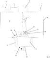
- Fig. 1 shows a schematic diagram of a device 1 according to an embodiment of the invention.
- the device 1 is used for the generative production of three-dimensional objects 2 by layer-wise selective solidification of solidifiable building material 3, namely a metal or plastic powder, by means of an energy beam 5 generated by a radiation generating device 4, namely a laser generating device, namely a laser beam.
- a radiation generating device 4 namely a laser generating device, namely a laser beam.
- the device 1 can be designed as a selective laser sintering device, for short SLS device, for performing selective laser sintering processes or as a selective laser melting device, for short SLM device, for performing selective laser melting processes.
- the radiation generating device 4 is assigned a beam deflecting device 6 for the targeted deflection of the energy beam 5 generated by the radiation generating device 4 onto a construction level 10 within a process chamber 7 of the device 1.
- the beam deflection device 6 comprises a number of suitable beam deflection elements (not shown), such as. B. Deflecting or deflecting mirrors. Since the radiation generating device 4 is a laser generating device, the beam deflecting device 6 can be referred to or viewed as a laser scanner, or scanner for short.
- the beam deflection device 6 is arranged in the beam path of the energy beam 5 generated by the radiation generating device 4.
- the device 1 comprises a coating device 8 for carrying out coating processes for applying a defined building material layer 9 of the solidifiable building material 3 on a building level 10, in which a selective solidification of the solidifiable building material 3 takes place, or on a building material layer previously applied as part of the implementation of a previous coating process 9.
- a building material layer 9 previously applied in the course of carrying out a previous coating process can also be referred to or regarded as building level 10, since a selective solidification of the solidifiable building material 3 also takes place in this level.
- the coating device 8 is, as indicated by the horizontally aligned double arrow, mounted so as to be movable relative to the building plane 10 and comprises one or more coating elements (not designated separately), that is to say, for example, coating blades.
- the device 1 further comprises a detection device 11 for detecting the quality, in particular the surface, of a layer of building material layer 9 applied by means of the coating device 8 in the context of carrying out a coating process, at least in sections qualitatively or quantitatively describing layer information.
- the acquisition device 11 is set up to acquire corresponding layer information during a coating process carried out by means of the coating device 8.
- the detection device 11 is arranged in the coating device 8. Because the detection device 11 is arranged in the coating device 8, the movement path of the detection device 11 is identical to the movement path of the coating device 8 in the context of a coating process.
- the acquisition device 11 is an image acquisition device, in particular a camera device, for acquiring the quality, in particular the surface, of layer image information that is applied at least in sections by means of the coating device 8 in the context of carrying out a coating process.
- the image acquisition device is a line camera, which is characterized by a comparatively high lateral resolution.
- the image acquisition device is therefore set up to receive corresponding slice image information one-dimensionally, i. H. in columns or rows.
- the focus of the image capturing device is of course aligned or adjusted to a building material layer (area) to be captured.
- the image capturing device is expediently provided with lighting means, i. H. z. B. a device for generating a flashlight, equipped for at least temporary illumination or illumination of a building material layer area to be detected.
- the detection device 11 By means of the detection device 11 it is possible to detect the quality, in particular the surface, of a building material layer 9 applied by means of the coating device 8 during a coating process.
- the quality of a building material layer 9 applied by means of the coating device 8 relates in particular to parameters such as smoothness, layer thickness, generally the order of the building material layer 9, in particular its surface.
- Layers of building material 9 applied by means of the coating device 8, which are to be recorded or recorded with regard to their quality, can also be already solidified building material layer (areas) and thus sections of the three-dimensional object 2 to be produced should be understood.
- Corresponding layer information can therefore also describe the quality of three-dimensional objects 2 or object surfaces, so that it is also possible to detect the quality of three-dimensional objects or object surfaces.
- the determination of the quality of corresponding building material layers 9 takes place in each case accompanied by corresponding coating processes or simultaneously with the implementation of corresponding coating processes for applying defined building material layers to a building level 10.
- the detection device 11 also enables (early) detection of impairments, i. E. H. Damage or defects to the coating device 8 are possible, since these are directly reflected in the building material layer 9 applied by means of the coating device 8 and can thus be described using corresponding layer information.
- impairments of a coating device 8 can be recognized by the fact that a defined distance between the applied building material layer 9 and the detection device 11 changes. This change in distance can, for. B. due to changes in focus of the detection device 11, affect the slice information and are therefore mapped via corresponding slice information.
- the acquisition device 11 embodied as an image acquisition device in the exemplary embodiments shown in the figures, corresponding changes in distance can cause changes in the resolution, the focus, the brightness, etc.
- the operation of the beam generating device 4 is controlled via a control device (not shown) assigned to the beam generating device 4.
- the control device is set up to generate control information controlling the operation of the beam generation device 4 and to communicate it to the beam generation device 4.
- Corresponding control information can contain irradiation information which, by means of the energy beam 5, describes regions to be selectively solidified, applied by means of the coating device 8, and / or beam properties, in particular energy densities, intensities, etc., of an energy beam 5 to be generated or generated.
- irradiation information which, by means of the energy beam 5, describes regions to be selectively solidified, applied by means of the coating device 8, and / or beam properties, in particular energy densities, intensities, etc., of an energy beam 5 to be generated or generated.
- the radiation generating device 4 can be operated in such a way that an energy beam 5 is generated after the completion of a coating process carried out by means of the coating device 8 (cf. Fig. 1 ).
- the solidification of the building material 3 only takes place after the coating process has ended, that is to say typically also after the corresponding layer information has been recorded.
- the energy beam 5 is directed via the beam deflection device 6 onto an area of a building material layer 9 applied by means of the coating device 8, for which the one detection device 11 has already acquired corresponding layer information.
- This is expedient as certain beam properties of the energy beam 5 can be adapted or set as a function of the quality of the applied building material layer 9 described by the layer information.
- irradiation of a building material layer 9 can also be omitted if the quality of the applied building material layer 9 does not meet certain specifiable or predefined quality criteria.
- user information can be output to a user via the control device, which shows a user a building material layer 9 which does not meet the corresponding quality criteria after a coating process has been carried out.
- the beam generating device 4 can be operated in such a way that an energy beam 5 is (still) generated during a coating process carried out by means of the coating device 8.
- the solidification of the building material 3 already takes place during the coating process, that is to say typically during the acquisition of the corresponding layer information.
- This variant enables a particular shortening of non-productive times as well as a particular acceleration of additive building processes, since coating, recording of corresponding layer information and irradiation can be carried out (essentially) simultaneously or at short intervals.
- the energy beam 5 is also directed via the beam deflection device 6 onto an area of a building material layer 9 applied by means of the coating device 8, for which the detection device 11 has already acquired corresponding layer information.
- the energy beam 5 is therefore tracked after the coating device 8 (cf. dashed illustration). This is useful as certain beam properties of the Energy beam 5 can be adapted or adjusted as a function of the quality of the applied building material layer 8 described by the layer information.
- irradiation of a building material layer 9 can also be omitted in this exemplary embodiment, provided that the quality of the applied building material layer 9 does not meet certain predeterminable or predetermined quality criteria.
- user information can be output to a user, which shows a user a building material layer 9 which does not meet the corresponding quality criteria after a coating process has been carried out.
- the or a further energy beam 5 is directed via the beam deflection device 6 onto an area of a building material layer 9 applied by means of the coating device 8, for which the detection device 11 has not yet recorded any corresponding layer information.
- the or a further energy beam 5 can therefore also be presented to the coating device 8 in advance.
- the device 1 additionally has a deflecting device 13 mounted movably relative to the construction level 10 for deflecting the protective gas flow flowing into the process chamber 7 into at least one may comprise a deflection direction different from a direction of inflow.
- the deflection device 13 is arranged on the coating device 8.
- the deflecting device 13 here comprises a plurality of deflecting elements connected to one another, by means of which a protective gas flow that circulates through the process chamber 7 can be generated.
- the cleaning device 12 is set up to use a fluid cleaning medium, d. H. z. B. a gas to flow onto or along at least one detection element to be cleaned.
- the device 1 naturally includes further functional components which are used to implement generative construction processes and thus for generative production three-dimensional objects 2 are required.
- these include, in particular, a housing device 14 with the process chamber 7, a support device 15 for carrying three-dimensional objects 2 to be produced or produced, the support device 15, as indicated by the vertically aligned double arrow, comprising a (vertically) movably mounted support element 16, a building material application and / or metering device (not shown) for applying and / or metering building material 3 into the process chamber 7.
- the device 1 can also have a further detection device for detecting, in particular the dimensions and / or the shape and / or the temperature, describing melting range information of a melted building material layer area ("melt pool") generated by means of the at least one energy beam 5. , as well as at least one evaluation device assigned to the further acquisition device for evaluating acquired melting range information with regard to a quality of the at least one three-dimensional object 2 to be produced. In this way, generative building processes can be monitored even better in the manner of a melt pool analysis and the quality of three-dimensional objects 2 to be produced can be better anticipated or calculated in advance.
- a further detection device for detecting, in particular the dimensions and / or the shape and / or the temperature, describing melting range information of a melted building material layer area ("melt pool") generated by means of the at least one energy beam 5.
- at least one evaluation device assigned to the further acquisition device for evaluating acquired melting range information with regard to a quality of the at least one three-dimensional object 2 to be produced.
- the device 1 can also include an interception device (not shown) for intercepting partially solidified and / or non-solidified building material 3 which, as a result of the construction process, is released from a building material layer 9 to be solidified and accelerated into the process chamber 7 in an uncontrolled manner.
- a corresponding interception device typically has a, z. B. slot-like, passage opening for the passage of the energy beam 5.
- a corresponding interception device can also be mounted so as to be movable relative to the building level 10.
- a method for the generative production of three-dimensional objects 2 can be implemented by layer-wise selective consolidation of a consolidatable building material 3 by means of an energy beam 5 generated by a radiation generator 4 for generating an energy beam 5 for consolidating a hardenable building material 3.
- the method is characterized in that, during a coating process carried out by means of a coating device 8, the quality, in particular the surface, of a layer of building material 9 applied in the course of the coating process describing layer information is recorded.
Description
Die Erfindung betrifft eine Vorrichtung zur generativen Herstellung wenigstens eines dreidimensionalen Objekts durch schichtweises selektives Verfestigen wenigstens eines verfestigbaren Baumaterials vermittels wenigstens eines von wenigstens einer Strahlungserzeugungseinrichtung erzeugten Energiestrahls.The invention relates to a device for the generative production of at least one three-dimensional object by layer-wise selective solidification of at least one solidifiable building material by means of at least one energy beam generated by at least one radiation generating device.
Derartige Vorrichtungen sind zur generativen Herstellung dreidimensionaler Objekte mit unterschiedlichen Querschnittsgeometrien dem Grunde nach bekannt. Herzustellende dreidimensionale Objekte werden durch schichtweises selektives Verfestigen eines verfestigbaren Baumaterials in entsprechenden Querschnittsbereichen der herzustellenden Objekte entsprechenden Bereichen vermittels eines von einer Strahlungserzeugungseinrichtung erzeugten Energiestrahls sukzessive aufgebaut.Such devices are basically known for the generative production of three-dimensional objects with different cross-sectional geometries. Three-dimensional objects to be produced are built up successively by layer-by-layer selective consolidation of a consolidatable building material in corresponding cross-sectional areas of the objects to be produced by means of an energy beam generated by a radiation generator.
Entsprechende Vorrichtungen umfassen u.a. eine Strahlerzeugungseinrichtung zur Erzeugung eines Energiestrahls zur Verfestigung eines verfestigbaren Baumaterials sowie eine Beschichtungseinrichtung zur Durchführung eines Beschichtungsvorgangs zur Aufbringung einer definierten Baumaterialschicht des verfestigbaren Baumaterials auf eine Bauebene oder auf eine im Rahmen der Durchführung eines vorherigen Beschichtungsvorgangs zuvor aufgebrachte Baumaterialschicht.Corresponding devices include, inter alia, a beam generating device for generating an energy beam for solidifying a solidifiable building material and a coating device for carrying out a coating process for applying a defined building material layer of the solidifiable building material on a building level or on a building material layer previously applied in the course of carrying out a previous coating process.
Für eine exakte selektive Verfestigung des verfestigbaren Baumaterials, welche eine wesentliche Voraussetzung für die Herstellung qualitativ hochwertiger dreidimensionaler Objekte ist, ist eine hohe Güte der vermittels der Beschichtungseinrichtung aufgebrachten Baumaterialschichten von erheblicher Bedeutung.For an exact selective consolidation of the consolidatable building material, which is an essential prerequisite for the production of high quality three-dimensional objects, a high quality of the building material layers applied by means of the coating device is of considerable importance.
Die Güte jeweiliger vermittels entsprechender Beschichtungseinrichtungen aufgebrachter Baumaterialschichten ist bis dato nur nach Beendigung der Durchführung eines Beschichtungsvorgangs erfassbar. Dies ist zeitaufwändig und insoweit verbesserungswürdig.The quality of the respective layers of building material applied by means of corresponding coating devices has so far only been ascertainable after the completion of a coating process. This is time-consuming and in this respect could be improved.
Die Druckschriften
Der Erfindung liegt die Aufgabe zugrunde, eine demgegenüber verbesserte Vorrichtung zur generativen Herstellung wenigstens eines dreidimensionalen Objekts anzugeben.The invention is based on the object of specifying a device for the generative production of at least one three-dimensional object which is improved in comparison.
Die Aufgabe wird durch eine Vorrichtung gemäß Anspruch 1 und ein Verfahren gemäß Anspruch 11 gelöst. Die jeweiligen abhängigen Ansprüche betreffen zweckmäßige Ausführungsformen der Vorrichtung.The object is achieved by a device according to
Die hierin beschriebene Vorrichtung dient der generativen Herstellung wenigstens eines dreidimensionalen Objekts durch schichtweises selektives Verfestigen wenigstens eines verfestigbaren Baumaterials vermittels wenigstens eines von wenigstens einer Strahlungserzeugungseinrichtung erzeugten Energiestrahls. Ein entsprechend verfestigbares Baumaterial ist typischerweise pulverartig bzw. pulverförmig. Bei dem Baumaterial kann es sich sonach z. B. um ein entsprechend verfestigbares Metallpulver(gemisch) und/oder um ein entsprechend verfestigbares Kunststoffpulver(gemisch) handeln.The device described herein is used for the generative production of at least one three-dimensional object by layer-wise selective solidification of at least one solidifiable building material by means of at least one energy beam generated by at least one radiation generating device. A correspondingly solidifiable building material is typically powdery or powdery. The building material can therefore be z. B. a correspondingly solidifiable metal powder (mixture) and / or a correspondingly solidifiable plastic powder (mixture).
Bei einer entsprechenden Strahlungserzeugungseinrichtung kann es sich um eine Lasererzeugungseinrichtung zur Erzeugung eines Laserstrahls, kurz einen Laser, handeln bzw. kann die Strahlungserzeugungseinrichtung wenigstens eine(n) solche(n) umfassen. In diesem Fall kann die Vorrichtung z. B. als selektive Lasersintervorrichtung, kurz SLS-Vorrichtung, zur Durchführung selektiver Lasersinterprozesse oder als selektive Laserschmelzvorrichtung, kurz SLM-Vorrichtung, zur Durchführung selektiver Laserschmelzprozesse ausgebildet sein. Selbstverständlich kann es sich bei einer entsprechenden Strahlungserzeugungseinrichtung auch um eine Teilchenerzeugungseinrichtung zur Erzeugung einer Teilchenstrahlung, handeln bzw. kann die Strahlungserzeugungseinrichtung wenigstens eine solche umfassen.A corresponding radiation generating device can be a laser generating device for generating a laser beam, or a laser for short, or the radiation generating device can comprise at least one such device. In this case the device can e.g. B. be designed as a selective laser sintering device, SLS device for short, for performing selective laser sintering processes or as a selective laser melting device, SLM device for short, for performing selective laser melting processes. Of course, a corresponding radiation generating device can also be a particle generating device for generating particle radiation, or the radiation generating device can include at least one such device.
Die Vorrichtung umfasst in an sich bekannter Weise wenigstens eine Beschichtungseinrichtung zur Durchführung wenigstens eines Beschichtungsvorgangs zur Aufbringung einer definierten Baumaterialschicht des wenigstens einen verfestigbaren Baumaterials auf eine Bauebene, in welcher eine selektive Verfestigung des verfestigbaren Baumaterials stattfindet, oder auf eine im Rahmen der Durchführung eines vorherigen Beschichtungsvorgangs zuvor aufgebrachte Baumaterialschicht. Eine im Rahmen der Durchführung eines vorherigen Beschichtungsvorgangs zuvor aufgebrachte Baumaterialschicht kann sonach ebenfalls als Bauebene bezeichnet bzw. erachtet werden, da in dieser ebenso selektive eine Verfestigung eines verfestigbaren Baumaterials stattfindet.The device comprises in a manner known per se at least one coating device for carrying out at least one coating process for applying a defined building material layer of the at least one solidifiable building material on a building level in which a selective solidification of the solidifiable building material takes place, or on one in the context of carrying out a previous coating process previously applied building material layer. A building material layer previously applied in the course of carrying out a previous coating process can therefore also be referred to or regarded as a building level, since solidification of a solidifiable building material also takes place in this level.
Eine entsprechende Beschichtungseinrichtung umfasst erfindungsgemäß ein oder mehrere Beschichterelemente, d. h. z. B. Beschichterklingen, welche zur Ausbildung definierter Baumaterialschichten über eine Bauebene bewegt werden. Entsprechend ist eine Beschichtungseinrichtung erfindungsgemäß bewegbar relativ zu einer Bauebene gelagert.According to the invention, a corresponding coating device comprises one or more coating elements, that is to say, for example, coating blades, which are moved over a building plane in order to form defined layers of building material. According to the invention, a coating device is accordingly mounted so as to be movable relative to a building plane.
Die Vorrichtung umfasst ferner wenigstens eine Erfassungseinrichtung zur Erfassung von die Güte, insbesondere der Oberfläche, einer vermittels der Beschichtungseinrichtung im Rahmen der Durchführung eines Beschichtungsvorgangs aufgebrachten Baumaterialschicht zumindest abschnittsweise beschreibenden Schichtinformationen. Die wenigstens eine Erfassungseinrichtung ist dazu eingerichtet, entsprechende Schichtinformationen während eines vermittels der Beschichtungseinrichtung durchgeführten Beschichtungsvorgangs zu erfassen. Vermittels einer entsprechenden Erfassungseinrichtung ist es sonach möglich, die Güte, insbesondere der Oberfläche, einer vermittels der Beschichtungseinrichtung aufgebrachten Baumaterialschicht bereits während eines vermittels der Beschichtungseinrichtung durchgeführten Beschichtungsvorgangs zu erfassen. Die Erfassungseinrichtung erfasst hierzu entsprechende Schichtinformationen, welche die Güte, insbesondere der Oberfläche, einer vermittels der Beschichtungseinrichtung im Rahmen der Durchführung eines Beschichtungsvorgangs aufgebrachten Baumaterialschicht zumindest abschnittsweise qualitativ oder quantitativ beschreiben. Die Güte einer vermittels der Beschichtungseinrichtung aufgebrachten Baumaterialschicht betrifft insbesondere Parameter, wie Glattheit, Schichtdicke allgemein die Ordnung, der Baumaterialschicht respektive deren Oberfläche.The device further comprises at least one detection device for detecting the quality, in particular the surface, of a layer information that describes at least sections of the building material layer applied by means of the coating device in the course of carrying out a coating process. The at least one detection device is set up to detect corresponding layer information during a coating process carried out by means of the coating device. By means of a corresponding detection device, it is therefore possible to detect the quality, in particular of the surface, of a layer of building material applied by means of the coating device during a coating process carried out by means of the coating device. For this purpose, the acquisition device acquires corresponding layer information which, at least in sections, qualitatively or quantitatively describes the quality, in particular the surface, of a building material layer applied by means of the coating device in the course of carrying out a coating process. The quality of a building material layer applied by means of the coating device relates in particular to parameters such as smoothness, layer thickness, generally the order of the building material layer or its surface.
Unter im Hinblick auf ihre Güte zu erfassenden bzw. erfassten, vermittels der Beschichtungseinrichtung aufgebrachten Baumaterialschichten können auch bereits verfestigte Baumaterialschicht(bereiche) und somit Abschnitte eines herzustellenden dreidimensionalen Objekts zu verstehen sein. Mithin können entsprechende Schichtinformationen auch die Güte von dreidimensionalen Objekten bzw. Objektoberflächen beschreiben, so dass auch eine Erfassung der Güte von dreidimensionalen Objekten bzw. Objektoberflächen möglich ist, was z. B. bei der Herstellung von Hybridbauteilen zweckmäßig sein kann, um bauraumbezogene Konturen aufzunehmen bzw. zu erzeugen.Building material layers that are to be detected or detected with regard to their quality and applied by means of the coating device can also be understood to mean already solidified building material layer (areas) and thus sections of a three-dimensional object to be produced. Corresponding layer information can therefore also describe the quality of three-dimensional objects or object surfaces, so that the quality of three-dimensional objects or object surfaces can also be recorded. B. can be useful in the production of hybrid components to record or create space-related contours.
Die Erfassung der Güte entsprechender Baumaterialschichten kann in jedem Fall mit entsprechenden Beschichtungsvorgängen einhergehen; die Erfassung der Güte entsprechender Baumaterialschichten erfolgt also simultan mit der Durchführung entsprechender Beschichtungsvorgänge zur Aufbringung definierter Baumaterialschichten auf eine Bauebene. Derart können Nebenzeiten reduziert und generative Bauprozesse insgesamt beschleunigt werden. Im Vergleich zu dem eingangs beschriebenen Stand der Technik ist es nicht erforderlich, die Beendigung der Durchführung eines Beschichtungsvorgangs abzuwarten, um die Güte einer jeweiligen im Rahmen des Beschichtungsvorgangs aufgebrachten Baumaterialschicht zu erfassen. Die Erfassung der Güte, insbesondere der Oberfläche, entsprechender Baumaterialschichten benötigt zudem nicht notwendig Bedienpersonal, was sich in fertigungs- bzw. prozesstechnischer und somit auch wirtschaftlicher Hinsicht positiv auf die Prozessführung auswirkt.The determination of the quality of corresponding building material layers can in any case go hand in hand with corresponding coating processes; the determination of the quality of corresponding layers of building material is therefore carried out simultaneously with the implementation of corresponding coating processes for applying defined layers of building material to a building level. In this way, non-productive times can be reduced and generative construction processes can be accelerated overall. In comparison to the prior art described at the beginning, it is not necessary to wait for the completion of the implementation of a coating process in order to determine the quality of a respective one applied in the course of the coating process To capture building material layer. The detection of the quality, in particular the surface, of the corresponding layers of building material also does not necessarily require operating personnel, which has a positive effect on the process management in terms of production or process technology and thus also in economic terms.
Über die Erfassungseinrichtung ist zudem eine (frühzeitige) Erfassung von Beeinträchtigungen, d. h. Beschädigungen bzw. Defekten, einer Beschichtungseinrichtung möglich, da sich diese unmittelbar in der vermittels der Beschichtungseinrichtung aufgebrachten Baumaterialschicht widerspiegeln und so über entsprechende Schichtinformationen beschrieben werden können. Typischerweise sind Beeinträchtigungen einer Beschichtungseinrichtung daran zu erkennen, dass sich ein definierter Abstand zwischen der aufgebrachten Baumaterialschicht und der Erfassungseinrichtung ändert. Diese Abstandsänderung kann sich auf die Schichtinformationen auswirken und sonach über entsprechende Schichtinformationen abgebildet werden. Bei einer, wie im Folgenden erläutert, als Bilderfassungseinrichtung ausgebildeten oder eine solche umfassenden Erfassungseinrichtung können entsprechende Abstandsänderungen Änderungen der Auflösung, Helligkeit, etc. bedingen.The detection device can also be used to (early) detect impairments, i. H. Damage or defects to a coating device are possible, since these are directly reflected in the layer of building material applied by means of the coating device and can thus be described using corresponding layer information. Typically, impairments of a coating device can be recognized by the fact that a defined distance between the applied building material layer and the detection device changes. This change in distance can affect the slice information and can therefore be mapped using corresponding slice information. In the case of a capturing device designed as an image capturing device, as explained below, or a capturing device comprising such a device, corresponding changes in distance may result in changes in resolution, brightness, etc.
Eine entsprechende Erfassungseinrichtung kann insbesondere als eine Bilderfassungseinrichtung, insbesondere eine Kameraeinrichtung, zur Erfassung von die Güte, insbesondere der Oberfläche, einer vermittels der Beschichtungseinrichtung im Rahmen der Durchführung eines Beschichtungsvorgangs aufgebrachten Baumaterialschicht zumindest abschnittsweise beschreibenden Schichtbildinformationen ausgebildet ist oder wenigstens eine solche umfasst. Entsprechende Bilderfassungseinrichtungen können z. B. als CCD-Kamera ausgebildet sein bzw. eine CCD- oder sonstige optische Sensorik umfassen. Der Fokus entsprechender Bilderfassungs- bzw. Kameraeinrichtungen ist selbstverständlich auf eine(n) zu erfassende(n) Baumaterialschicht(bereich) ausgerichtet bzw. eingestellt.A corresponding acquisition device can in particular be designed as an image acquisition device, in particular a camera device, for acquiring the quality, in particular the surface, of a layer image information that is applied at least in sections by means of the coating device in the context of carrying out a coating process, or includes at least one such layer image information. Corresponding image capturing devices can, for. B. be designed as a CCD camera or comprise a CCD or other optical sensors. The focus of corresponding image recording or camera devices is of course aligned or set on a building material layer (area) to be recorded.
Eine entsprechende Bilderfassungseinrichtung kann mit Beleuchtungsmitteln zur zumindest zeitweisen Aus- oder Beleuchtung eines zu erfassenden Baumaterialschichtbereichs ausgestattet sein. Bei entsprechenden Beleuchtungsmitteln kann es sich, insbesondere bei einer Kameraeinrichtung, z. B. um eine Einrichtung zur Erzeugung eines Blitzlichts handeln.A corresponding image capturing device can be equipped with lighting means for at least temporarily illuminating or illuminating a building material layer area to be captured. In the case of appropriate lighting means, in particular in the case of a camera device, e.g. B. be a device for generating a flashlight.
Grundsätzlich kann eine entsprechende Bilderfassungseinrichtung dazu eingerichtet sein, entsprechende Schichtbildinformationen eindimensional, d. h. spalten- oder zeilenmäßig, oder mehrdimensional zu erfassen. Bei einer Bilderfassungseinrichtung kann es sich sonach um eine Zeilenkamera handeln, welche sich durch eine vergleichsweise hohe laterale Auflösung auszeichnet. In diesem Zusammenhang sind Auflösungen von 1600 dpi oder mehr denkbar.In principle, a corresponding image acquisition device can be set up to acquire corresponding slice image information in one dimension, ie in columns or rows, or in multiple dimensions. An image acquisition device can therefore be a line camera, which can be viewed through a comparatively high lateral resolution. In this context, resolutions of 1600 dpi or more are conceivable.
Insgesamt ist damit eine verbesserte Vorrichtung zur generativen Herstellung wenigstens eines dreidimensionalen Objekts gegeben.Overall, this provides an improved device for the generative production of at least one three-dimensional object.
Neben den bisher genannten Funktionskomponenten der Vorrichtung umfasst die Vorrichtung selbstverständlich weitere Funktionskomponenten, welche zur Realisierung generativer Bauprozesse und somit zur generativen Herstellung dreidimensionaler Objekte typischerweise erforderlich sind. Unter Funktionskomponenten der Vorrichtung sind im Allgemeinen Komponenten oder Komponentengruppen zu verstehen, welche, typischerweise unmittelbar, im Zusammenhang mit einem generativen Bauprozess stehen. Hierzu zählt insbesondere eine Gehäuseeinrichtung mit wenigstens einer Prozesskammer, im Allgemeinen einem abgeschlossenen Volumen, in welchem generative Bauprozesse zur Herstellung dreidimensionaler Objekte stattfinden, wenigstens eine Trageinrichtung zum Tragen herzustellender bzw. hergestellter dreidimensionaler Objekte, wobei die Trageinrichtung wenigstens ein (höhen)beweglich gelagertes Tragelement umfassen kann, wenigstens eine Baumaterialaufbring- und/oder Dosiereinrichtung zur Aufbringung und/oder Dosierung von Baumaterial in die Prozesskammer sowie wenigstens eine Strahlablenkeinrichtung zur gezielten Ablenkung eines von der Strahlungserzeugungseinrichtung erzeugten Energiestrahls auf einen bestimmten Bereich innerhalb einer Prozesskammer der Vorrichtung. In einer entsprechenden Prozesskammer herrscht typischerweise eine inerte Schutzgasatmosphäre, d. h. die Prozesskammer ist typischerweise mit einem inerten Schutzgas, z. B. Argon, Stickstoff, etc., befüllt bzw. wird von einem solchen durchströmt.In addition to the previously mentioned functional components of the device, the device naturally includes further functional components which are typically required for the implementation of generative construction processes and thus for the generative production of three-dimensional objects. Functional components of the device are generally to be understood as components or component groups which are typically directly related to a generative construction process. This includes, in particular, a housing device with at least one process chamber, generally a closed volume, in which generative construction processes for the production of three-dimensional objects take place, at least one support device for carrying three-dimensional objects to be produced or produced, the support device comprising at least one (vertically) movably mounted support element can, at least one building material application and / or metering device for applying and / or metering construction material in the process chamber and at least one beam deflection device for the targeted deflection of an energy beam generated by the radiation generating device to a specific area within a process chamber of the device. An inert protective gas atmosphere typically prevails in a corresponding process chamber, i. H. the process chamber is typically covered with an inert protective gas, e.g. B. argon, nitrogen, etc., filled or is flowed through by such.
Die vorstehende Aufzählung entsprechender Funktionskomponenten der Vorrichtung ist nicht abschließend.The above list of corresponding functional components of the device is not exhaustive.
Eine entsprechende Erfassungseinrichtung ist erfindungsgemäß relativ zu einer (zu beschichtenden) Bauebene bzw. einer aufgebrachten Baumaterialschicht bewegbar gelagert. Die Erfassungseinrichtung wird so einer Bewegung einer relativ zu einer (zu beschichtenden) Bauebene bzw. einer aufgebrachten Baumaterialschicht bewegbar gelagerten Beschichtungseinrichtung im Rahmen der Durchführung eines Beschichtungsvorgangs nachgeführt. Die Bewegungsbahn der Erfassungseinrichtung ist erfindungsgemäß identisch mit der Bewegungsbahn der Beschichtungseinrichtung im Rahmen eines Beschichtungsvorgangs.According to the invention, a corresponding detection device is movably mounted relative to a building plane (to be coated) or an applied building material layer. The detection device is thus tracked to a movement of a coating device mounted movably relative to a building plane (to be coated) or an applied building material layer in the course of carrying out a coating process. According to the invention, the movement path of the detection device is identical to the movement path of the coating device in the context of a coating process.
Erfindungsgemäß, weil wenig Raum innerhalb einer vorrichtungsseitigen Prozesskammer beanspruchend, ist eine entsprechende Erfassungseinrichtung dabei mit einer relativ zu einer (zu beschichtenden) Bauebene bzw. einer aufgebrachten Baumaterialschicht bewegbar gelagerten Beschichtungseinrichtung bewegungsgekoppelt. Die Erfassungseinrichtung wird derart so bei einer Bewegung der Beschichtungseinrichtung im Rahmen der Durchführung eines Beschichtungsvorgangs mitbewegt bzw. der Bewegung der Beschichtungseinrichtung nachgeführt. Die Bewegungsbahn der Erfassungseinrichtung ist erfindungsgemäß identisch mit der Bewegungsbahn einer Beschichtungseinrichtung im Rahmen eines Beschichtungsvorgangs. Eine entsprechende Bewegungskopplung einer entsprechenden Erfassungseinrichtung mit einer entsprechenden Beschichtungseinrichtung ist durch realisiert, dass die Erfassungseinrichtung zumindest abschnittsweise in der Beschichtungseinrichtung angeordnet oder ausgebildet ist. Eine Anordnung einer Erfassungseinrichtung in einer Beschichtungseinrichtung beinhaltet typischerweise eine stoff- und/oder kraft- und/oder formschlüssige, gegebenenfalls (beschädigungs- bzw. zerstörungsfrei) lösbare, bauliche Verbindung zwischen der Erfassungseinrichtung und der Beschichtungseinrichtung. Eine Ausbildung einer Erfassungseinrichtung in einer Beschichtungseinrichtung beinhaltet erfindungsgemäß eine bauliche Integration der Erfassungseinrichtung in die Beschichtungseinrichtung.According to the invention, because it takes up little space within a device-side process chamber, a corresponding detection device is coupled to a coating device movably mounted relative to a building plane (to be coated) or an applied building material layer. The detection device is thus moved along with a movement of the coating device in the context of carrying out a coating process or follows the movement of the coating device. According to the invention, the movement path of the detection device is identical to the movement path of a coating device in the context of a coating process. A corresponding movement coupling of a corresponding detection device with a corresponding coating device is implemented in that the detection device is arranged or formed at least in sections in the coating device. An arrangement of a detection device in a coating device typically includes a material and / or non-positive and / or form-fitting, possibly detachable (damage-free or non-destructive) structural connection between the detection device and the coating device. An embodiment of a detection device in a coating device includes, according to the invention, a structural integration of the detection device into the coating device.
Nachfolgend werden unterschiedliche Betriebsmodi der Strahlerzeugungseinrichtung beschrieben, gemäß welchen eine Erzeugung eines Energiestrahls und eine vermittels des erzeugten Energiestrahls erfolgende Verfestigung verfestigbaren Baumaterials entweder nach Beendigung der Durchführung eines Beschichtungsvorgangs oder bereits während eines Beschichtungsvorgangs möglich ist. Die Steuerung des Betriebs der wenigstens einen Strahlerzeugungseinrichtung erfolgt über eine der Strahlerzeugungseinrichtung zugeordnete Steuereinrichtung. Die Steuereinrichtung ist dazu eingerichtet, den Betrieb der wenigstens einen Strahlerzeugungseinrichtung steuernde Steuerinformationen zu erzeugen und an die Strahlerzeugungseinrichtung zu kommunizieren.In the following, different operating modes of the beam generating device are described, according to which an energy beam can be generated and solidified building material can be solidified by means of the generated energy beam either after the completion of a coating process or already during a coating process. The operation of the at least one beam generating device is controlled via a control device assigned to the beam generating device. The control device is set up to generate control information that controls the operation of the at least one beam generation device and to communicate it to the beam generation device.
Eine entsprechende Strahlungserzeugungseinrichtung kann entsprechend dazu eingerichtet sein, einen Energiestrahl zur Verfestigung eines verfestigbaren Baumaterials nach Beendigung eines vermittels der Beschichtungseinrichtung durchgeführten Beschichtungsvorgangs zu erzeugen. In dieser Variante erfolgt die Verfestigung des Baumaterials erst nach Beendigung des Beschichtungsvorgangs, d. h. typischerweise auch nach der Erfassung entsprechender Schichtinformationen. Der Energiestrahl kann dabei, insbesondere über wenigstens eine Strahlablenkeinrichtung, auf einen Bereich einer aufgebrachten Baumaterialschicht lenkbar sein, zu welchem die wenigstens eine Erfassungseinrichtung bereits entsprechende Schichtinformationen erfasst hat. Dies ist zweckmäßig, als bestimmte Strahleigenschaften des Energiestrahls in Abhängigkeit der durch die Schichtinformationen beschriebenen Güte der aufgebrachten Baumaterialschicht angepasst bzw. eingestellt werden können. Gegebenenfalls kann eine Bestrahlung einer Baumaterialschicht auch unterbleiben, sofern die Güte der aufgebrachten Baumaterialschicht bestimmten vorgebbaren oder vorgegebenen Qualitätskriterien nicht genügt. In diesem Fall kann eine Nutzerinformation an einen Nutzer ausgegeben werden, welche einem Nutzer eine entsprechenden Qualitätskriterien nicht genügende Baumaterialschicht nach Durchführung eines Beschichtungsvorgangs anzeigt.A corresponding radiation generating device can be set up accordingly to generate an energy beam for solidifying a solidifiable To produce building material after completion of a coating process carried out by means of the coating device. In this variant, the solidification of the building material only takes place after the coating process has been completed, i. H. typically even after the relevant shift information has been recorded. The energy beam can be steered, in particular via at least one beam deflection device, onto an area of an applied building material layer, for which the at least one detection device has already acquired corresponding layer information. This is useful as certain beam properties of the energy beam can be adapted or set as a function of the quality of the applied building material layer described by the layer information. If necessary, irradiation of a building material layer can also be omitted if the quality of the applied building material layer does not meet certain predefinable or predetermined quality criteria. In this case, user information can be output to a user, which shows a user a building material layer that does not meet the corresponding quality criteria after a coating process has been carried out.
Alternativ kann eine entsprechende Strahlerzeugungseinrichtung dazu eingerichtet sein, einen Energiestrahl zur Verfestigung des wenigstens einen verfestigbaren Baumaterials (noch) während eines vermittels der Beschichtungseinrichtung durchgeführten Beschichtungsvorgangs zu erzeugen. In dieser Variante erfolgt die Verfestigung des Baumaterials bereits während des Beschichtungsvorgangs, d. h. typischerweise während der Erfassung entsprechender Schichtinformationen. Diese Variante ermöglicht eine besondere Verkürzung von Nebenzeiten sowie eine besondere Beschleunigung generativer Bauprozesse, da Beschichten, Erfassen entsprechender Schichtinformationen und Bestrahlen (im Wesentlichen) simultan oder in engen zeitlichen Abständen durchgeführt werden können. Der Energiestrahl kann dabei ebenso, insbesondere über wenigstens eine Strahlablenkeinrichtung, auf einen Bereich einer vermittels der Beschichtungseinrichtung aufgebrachten Baumaterialschicht lenkbar sein, zu welchem die wenigstens eine Erfassungseinrichtung bereits entsprechende Schichtinformationen erfasst hat. Der Energiestrahl kann der Beschichtungseinrichtung sonach nachlaufend nachgeführt werden. Dies ist, wie vorstehend erwähnt, zweckmäßig, als bestimmte Strahleigenschaften des Energiestrahls hier in Abhängigkeit der durch die Schichtinformationen beschriebenen Güte der aufgebrachten Baumaterialschicht angepasst bzw. eingestellt werden können.Alternatively, a corresponding beam generating device can be set up to generate an energy beam for solidifying the at least one solidifiable building material (still) during a coating process carried out by means of the coating device. In this variant, the solidification of the building material already takes place during the coating process, i.e. H. typically during the acquisition of the relevant shift information. This variant enables a particular shortening of non-productive times as well as a particular acceleration of generative construction processes, since coating, recording of the corresponding layer information and irradiation can be carried out (essentially) simultaneously or at short intervals. The energy beam can also be steered, in particular via at least one beam deflection device, onto a region of a layer of building material applied by means of the coating device, for which the at least one detection device has already acquired corresponding layer information. The energy beam can therefore be tracked after the coating device. As mentioned above, this is expedient as certain beam properties of the energy beam can be adapted or set here as a function of the quality of the applied building material layer described by the layer information.
Gegebenenfalls kann eine Bestrahlung einer Baumaterialschicht auch unterbleiben, sofern die Güte der aufgebrachten Baumaterialschicht bestimmten vorgebbaren oder vorgegebenen Qualitätskriterien nicht genügt. In diesem Fall kann eine Nutzerinformation an einen Nutzer ausgegeben werden, welche einem Nutzer eine entsprechenden Qualitätskriterien nicht genügende Baumaterialschicht nach Durchführung eines Beschichtungsvorgangs anzeigt.If necessary, irradiation of a building material layer can also be omitted if the quality of the applied building material layer does not meet certain predefinable or predetermined quality criteria. In this case, user information can be output to a user indicating a building material layer that does not meet a corresponding quality criteria for a user Implementation of a coating process indicates.
Denkbar ist es jedoch auch, dass der oder ein weiterer Energiestrahl, insbesondere über wenigstens eine Strahlablenkeinrichtung, auf einen Bereich einer vermittels der Beschichtungseinrichtung aufgebrachten Baumaterialschicht lenkbar ist, zu welchem die wenigstens eine Erfassungseinrichtung noch keine entsprechenden Schichtinformationen erfasst hat. Der oder ein weiterer Energiestrahl kann der Beschichtungseinrichtung sonach vorlaufend vorgeführt werden. Ein der Beschichtungseinrichtung vorlaufender und ein der Beschichtungseinrichtung nachlaufender Energiestrahl können sich in ihren Strahleigenschaften, insbesondere ihrer Energiedichte, Intensität, etc., unterscheiden; beispielsweise kann ein der Beschichtungseinrichtung vorlaufender Energiestrahl eine Vorfestigung des zu verfestigenden Baumaterials und ein der Beschichtungseinrichtung nachlaufender Energiestrahl eine Nachverfestigung des vorverfestigten Baumaterials bedingen.However, it is also conceivable that the or a further energy beam can be steered, in particular via at least one beam deflection device, onto an area of a building material layer applied by means of the coating device, for which the at least one detection device has not yet recorded any corresponding layer information. The or a further energy beam can therefore be presented in advance to the coating device. An energy beam preceding the coating device and one following the coating device can differ in their beam properties, in particular their energy density, intensity, etc.; For example, an energy beam leading to the coating device can cause pre-consolidation of the building material to be consolidated and an energy beam following the coating device can cause post-consolidation of the pre-consolidated building material.
Die Vorrichtung kann, wie erwähnt, wenigstens eine Steuereinrichtung zur Steuerung des Betriebs der wenigstens einen Strahlerzeugungseinrichtung umfassen. Die Steuereinrichtung kann dazu eingerichtet sein, den Betrieb der wenigstens einen Strahlerzeugungseinrichtung steuernde Steuerinformationen in Abhängigkeit erfasster Schichtinformationen zu erzeugen. Entsprechende Steuerinformationen können Bestrahlungsinformationen, welche vermittels des Energiestrahls zu bestrahlende Bereiche einer selektiv zu verfestigenden, vermittels der Beschichtungseinrichtung aufgebrachten Baumaterialschicht, und/oder Strahleigenschaften, insbesondere Energiedichten, Intensitäten, etc., eines zu erzeugenden oder erzeugten Energiestrahls beschreiben, beinhalten. Über die Steuereinrichtung ist es sonach möglich, in Abhängigkeit der über entsprechende Schichtinformationen beschriebenen Güte einer vermittels der Beschichtungseinrichtung aufgebrachten Baumaterialschicht bestimmte Bestrahlungsbereiche und/oder Strahleigenschaften eines Energiestrahls anzupassen bzw. einzustellen. Wie erwähnt, kann eine Bestrahlung einer Baumaterialschicht gegebenenfalls auch (bereichsweise bzw. lokal) unterbleiben, sofern die Güte der aufgebrachten Baumaterialschicht (bereichsweise bzw. lokal) bestimmten vorgebbaren oder vorgegebenen Qualitätskriterien nicht genügt.As mentioned, the device can comprise at least one control device for controlling the operation of the at least one beam generating device. The control device can be set up to generate control information controlling the operation of the at least one beam generating device as a function of the acquired slice information. Corresponding control information can contain irradiation information which, by means of the energy beam, describes regions to be selectively solidified, applied by means of the coating device, and / or beam properties, in particular energy densities, intensities, etc., of an energy beam to be generated or generated. Using the control device, it is therefore possible to adapt or set certain irradiation areas and / or beam properties of an energy beam as a function of the quality of a layer of building material applied by means of the coating device, which is described via corresponding layer information. As mentioned, irradiation of a building material layer can optionally also be omitted (in certain areas or locally) if the quality of the applied building material layer (in certain areas or locally) does not meet certain predeterminable or predetermined quality criteria.
Eine entsprechende Erfassungseinrichtung respektive dieser zugehörige, insbesondere optische, Erfassungselemente, wie optische Linsen, können bauprozessbedingt, z. B. durch Ablagerungen von feinen Baumaterial- und/oder von Schmauchpartikeln, verunreinigt werden. Der Erfassungseinrichtung kann deshalb wenigstens eine Reinigungseinrichtung zur Entfernung von bauprozessbedingten Verunreinigungen wenigstens eines der wenigstens einen Erfassungseinrichtung zugehörigen, insbesondere optischen, Erfassungselements, z. B. einer optischen Linse, zugeordnet sein. Eine entsprechende Reinigungseinrichtung kann dazu eingerichtet sein, ein fluides Reinigungsmedium auf ein oder entlang wenigstens eines zu reinigenden Erfassungselements zu strömen. Bei einem entsprechenden Reinigungsmedium kann es sich um ein Gas, d. h. z. B. um Kohlenstoffdioxid, Stickstoff, etc., handeln. Ein als Reinigungsmedium verwendetes Gas kann gleichermaßen auch ein inertes Schutzgas sein, welches in eine vorrichtungsseitige Prozesskammer eingeströmt wird.A corresponding detection device or, respectively, this associated, in particular optical, detection elements such as optical lenses, can be used depending on the construction process, e.g. B. be contaminated by deposits of fine building material and / or smoke particles. The detection device can therefore have at least one cleaning device for removing construction process-related contamination of at least one of the at least one detection device associated, in particular optical, detection element, e.g. B. an optical lens assigned. A corresponding cleaning device can be set up to flow a fluid cleaning medium onto or along at least one detection element to be cleaned. A corresponding cleaning medium can be a gas, ie carbon dioxide, nitrogen, etc., for example. A gas used as a cleaning medium can also be an inert protective gas, which flows into a device-side process chamber.
Sofern ein solches Schutzgas in bzw. durch eine vorrichtungsseitige Prozesskammer geströmt wird, kann die Vorrichtung wenigstens eine, insbesondere bewegbar relativ zu einer Bauebene gelagerte, Umlenkeinrichtung zur Umlenkung eines in eine Prozesskammer der Vorrichtung einströmenden Schutzgasstroms in wenigstens eine von einer Einströmungsrichtung verschiedene Umlenkrichtung umfassen. Derart können individuelle Schutzgasströmungen erzeugt werden. Eine entsprechende Umlenkeinrichtung kann mehrere innerhalb einer Prozesskammer angeordnete oder ausgebildete Umlenkelemente umfassen. Durch geeignete Anordnung und Ausrichtung entsprechender Umlenkelemente kann eine kreislaufartig durch eine Prozesskammer zirkulierende Schutzgasströmung erzeugt werden.If such a protective gas flows into or through a device-side process chamber, the device can comprise at least one deflection device, in particular movably mounted relative to a building plane, for deflecting a protective gas flow flowing into a process chamber of the device in at least one deflection direction different from a flow direction. In this way, individual protective gas flows can be generated. A corresponding deflection device can comprise a plurality of deflection elements arranged or formed within a process chamber. A protective gas flow that circulates in a circular manner through a process chamber can be generated by suitable arrangement and alignment of corresponding deflecting elements.
Die Vorrichtung kann ferner wenigstens eine weitere Erfassungseinrichtung zur Erfassung, insbesondere die Abmessungen und/oder die Form und/oder die Temperatur beschreibender, Schmelzbereichsinformationen eines vermittels des wenigstens einen Energiestrahls erzeugten aufgeschmolzenen Baumaterialschichtbereichs ("Schmelzpool"), sowie wenigstens eine der weiteren Erfassungseinrichtung zugeordnete Auswerteeinrichtung zur Auswertung erfasster Schmelzbereichsinformationen im Hinblick auf eine Güte des wenigstens einen herzustellenden dreidimensionalen Objekts umfassen. Derart können generative Bauprozesse nach Art einer sogenannten Schmelzpoolanalyse noch besser überwacht und die Güte herzustellender dreidimensionaler Objekte besser antizipiert bzw. vorausberechnet werden.The device can also have at least one further detection device for detecting, in particular the dimensions and / or the shape and / or the temperature, describing melting range information of a melted building material layer area ("melt pool") generated by means of the at least one energy beam, as well as at least one evaluation device assigned to the further detection device for evaluating acquired melting range information with regard to a quality of the at least one three-dimensional object to be produced. In this way, generative building processes can be monitored even better in the manner of a so-called melt pool analysis and the quality of the three-dimensional objects to be produced can be better anticipated or calculated in advance.
Die Vorrichtung kann zudem wenigstens eine Abfangeinrichtung zum Abfangen von teilverfestigtem und/oder nichtverfestigtem Baumaterial, welches sich bauprozessbedingt aus einer zu verfestigenden Baumaterialschicht löst und unkontrolliert in eine vorrichtungsseitige Prozesskammer beschleunigt ist, umfassen. Derart können Beeinträchtigungen der Güte einer vermittels der Beschichtungseinrichtung aufgebrachten Baumaterialschicht durch entsprechendes bauprozessbedingt aus einer zu verfestigenden Baumaterialschicht gelöstes und unkontrolliert in eine vorrichtungsseitige Prozesskammer beschleunigtes Baumaterial verhindert werden. Eine entsprechende Abfangeinrichtung weist typischerweise wenigstens eine, z. B. schlitzartige, Durchtrittsöffnung für den Durchtritt eines Energiestrahls auf. Eine entsprechende Abfangeinrichtung kann ebenso bewegbar relativ zu einer Bauebene gelagert sein.The device can also include at least one interception device for intercepting partially solidified and / or non-solidified building material which, as a result of the construction process, detaches itself from a building material layer to be solidified and is accelerated in an uncontrolled manner into a device-side process chamber. In this way, impairments of the quality of a layer of building material applied by means of the coating device can be caused by a layer of building material that is to be solidified and detached as a result of the corresponding building process Uncontrolled building material accelerated into a device-side process chamber can be prevented. A corresponding interception device typically has at least one, e.g. B. slot-like, passage opening for the passage of an energy beam. A corresponding interception device can also be mounted so as to be movable relative to a building plane.
Die Erfindung betrifft ferner ein Verfahren zur generativen Herstellung wenigstens eines dreidimensionalen Objekts durch schichtweises selektives Verfestigen wenigstens eines verfestigbaren Baumaterials vermittels wenigstens eines von wenigstens einer Strahlungserzeugungseinrichtung zur Erzeugung wenigstens eines Energiestrahls zur Verfestigung wenigstens eines verfestigbaren Baumaterials erzeugten Energiestrahls, insbesondere mit einer wie vorstehend beschriebenen Vorrichtung. Das Verfahren zeichnet sich dadurch aus, dass während eines vermittels einer Beschichtungseinrichtung durchgeführten Beschichtungsvorgangs die Güte, insbesondere der Oberfläche, einer im Rahmen des Beschichtungsvorgangs aufgebrachten Baumaterialschicht beschreibende Schichtinformationen erfasst werden.The invention also relates to a method for the generative production of at least one three-dimensional object by layer-wise selective solidification of at least one solidifiable building material by means of at least one of at least one radiation generating device for generating at least one energy beam for solidifying at least one solidifiable building material generated energy beam, in particular with a device as described above. The method is characterized in that, during a coating process carried out by means of a coating device, the quality, in particular of the surface, of a layer information describing the building material layer applied in the course of the coating process is recorded.
Im Rahmen des Verfahrens wird wenigstens eine bewegbar relativ zu einer (zu beschichtenden) Bauebene bzw. einer aufgebrachten Baumaterialschicht gelagerte Erfassungseinrichtung verwendet. Erfindungsgemäß ist es auch, wenigstens eine Beschichtungseinrichtung zur Durchführung wenigstens eines Beschichtungsvorgangs zur Aufbringung einer definierten Baumaterialschicht wenigstens eines verfestigbaren Baumaterials auf eine Bauebene oder auf eine vermittels der Beschichtungseinrichtung im Rahmen der Durchführung eines vorherigen Beschichtungsvorgangs zuvor aufgebrachte Baumaterialschicht wenigstens eines verfestigbaren Baumaterials zu verwenden, welche relativ zu einer Bauebene bewegbar gelagert ist. Die wenigstens eine Erfassungseinrichtung wird erfindungsgemäß mit der wenigstens einen Beschichtungseinrichtung bewegungsgekoppelt.In the context of the method, at least one detection device mounted movably relative to a building level (to be coated) or an applied building material layer is used. It is also according to the invention to use at least one coating device for performing at least one coating process for applying a defined building material layer of at least one solidifiable building material on a building level or on a building material layer of at least one solidifiable building material previously applied by means of the coating device in the context of performing a previous coating procedure, which relatively is mounted movable to a building level. According to the invention, the at least one detection device is coupled in terms of movement to the at least one coating device.
Im Rahmen des Verfahrens kann wenigstens eine Erfassungseinrichtung verwendet werden, welche als eine Bilderfassungseinrichtung, insbesondere eine Kameraeinrichtung, zur Erfassung von die Güte, insbesondere der Oberfläche, einer vermittels der Beschichtungseinrichtung im Rahmen der Durchführung eines Beschichtungsvorgangs aufgebrachten Baumaterialschicht zumindest abschnittsweise beschreibenden Schichtbildinformationen ausgebildet ist oder wenigstens eine solche umfasst.As part of the method, at least one detection device can be used which is designed as an image detection device, in particular a camera device, for detecting the quality, in particular the surface, of a layer image information applied at least in sections by means of the coating device in the context of carrying out a coating process, or at least includes such.
Im Rahmen des Verfahrens kann ein Energiestrahl zur Verfestigung des wenigstens einen verfestigbaren Baumaterials nach Beendigung der Erfassung entsprechender Schichtinformationen nach Beendigung eines vermittels der Beschichtungseinrichtung durchgeführten Beschichtungsvorgangs erzeugt werden. Der Energiestrahl kann, insbesondere über wenigstens eine Strahlablenkeinrichtung, auf einen Bereich einer vermittels der Beschichtungseinrichtung aufgebrachten Baumaterialschicht gelenkt werden, zu welchem die wenigstens eine Erfassungseinrichtung bereits entsprechende Schichtinformationen erfasst hat.In the context of the method, an energy beam to solidify the at least A solidifiable building material can be generated after the acquisition of corresponding layer information has ended after a coating process carried out by means of the coating device has been completed. The energy beam can be directed, in particular via at least one beam deflection device, onto a region of a layer of building material applied by means of the coating device, for which the at least one detection device has already acquired corresponding layer information.
Alternativ kann ein Energiestrahl zur Verfestigung des wenigstens einen verfestigbaren Baumaterials (noch) während der Erfassung entsprechender Schichtinformationen während eines vermittels der Beschichtungseinrichtung durchgeführten Beschichtungsvorgangs erzeugt werden. Der Energiestrahl kann, insbesondere über wenigstens eine Strahlablenkeinrichtung, auf einen Bereich einer vermittels der Beschichtungseinrichtung aufgebrachten Baumaterialschicht gelenkt werden, zu welchem die wenigstens eine Erfassungseinrichtung bereits entsprechende Schichtinformationen erfasst hat, oder auf einen Bereich einer vermittels der Beschichtungseinrichtung aufgebrachten Baumaterialschicht gelenkt werden, zu welchem die wenigstens eine Erfassungseinrichtung noch keine entsprechenden Schichtinformationen erfasst hat.Alternatively, an energy beam for solidifying the at least one solidifiable building material can (still) be generated during the acquisition of corresponding layer information during a coating process carried out by means of the coating device. The energy beam can be directed, in particular via at least one beam deflection device, onto an area of a building material layer applied by means of the coating device, for which the at least one detection device has already acquired corresponding layer information, or directed onto an area of a building material layer applied by means of the coating device, to which the at least one acquisition device has not yet acquired any corresponding slice information.
Im Rahmen des Verfahrens kann der Betrieb der wenigstens einen Strahlerzeugungseinrichtung über wenigstens eine Steuereinrichtung zur Steuerung des Betriebs der wenigstens einen Strahlerzeugungseinrichtung gesteuert werden, wobei die Steuereinrichtung den Betrieb der wenigstens einen Strahlerzeugungseinrichtung steuernde Steuerinformationen in Abhängigkeit erfasster Schichtinformationen erzeugt.As part of the method, the operation of the at least one beam generating device can be controlled via at least one control device for controlling the operation of the at least one beam generating device, the control device generating control information controlling the operation of the at least one beam generating device as a function of the acquired layer information.
Im Rahmen des Verfahrens können bauprozessbedingte Verunreinigungen wenigstens eines der wenigstens einen Erfassungseinrichtung zugehörigen, insbesondere optischen, Erfassungselements vermittels wenigstens einer der Erfassungseinrichtung zugeordneten Reinigungseinrichtung zur entfernt werden.In the context of the method, construction process-related contamination of at least one of the at least one detection device, in particular optical, detection element can be removed by means of at least one cleaning device assigned to the detection device.
Grundsätzlich gelten sämtliche Ausführungen im Zusammenhang mit der Vorrichtung analog für das Verfahren und umgekehrt.In principle, all statements in connection with the device apply analogously to the method and vice versa.
Die Erfindung ist anhand von Ausführungsbeispielen in den Zeichnungsfiguren näher erläutert. Dabei zeigen:
- Fig. 1 - 3
- je eine Prinzipdarstellung einer Vorrichtung gemäß einem Ausführungsbeispiel der Erfindung.
- Figs. 1-3
- each a schematic diagram of a device according to a Embodiment of the invention.
Die Vorrichtung 1 kann als selektive Lasersintervorrichtung, kurz SLS-Vorrichtung, zur Durchführung selektiver Lasersinterprozesse oder als selektive Laserschmelzvorrichtung, kurz SLM-Vorrichtung, zur Durchführung selektiver Laserschmelzprozesse ausgebildet sein.The
Der Strahlungserzeugungseinrichtung 4 ist eine Strahlablenkeinrichtung 6 zur gezielten Ablenkung des von der Strahlungserzeugungseinrichtung 4 erzeugten Energiestrahls 5 auf eine Bauebene 10 innerhalb einer Prozesskammer 7 der Vorrichtung 1 zugeordnet. Zur gezielten Ablenkung des Energiestrahls 5 umfasst die Strahlablenkeinrichtung 6 eine Anzahl an geeigneten Strahlablenkelementen (nicht gezeigt), wie z. B. Ab- oder Umlenkspiegeln. Da es sich bei der Strahlungserzeugungseinrichtung 4 um eine Lasererzeugungseinrichtung handelt, kann die Strahlablenkeinrichtung 6 als Laserscanner, kurz Scanner, bezeichnet bzw. erachtet werden. Die Strahlablenkeinrichtung 6 ist in dem Strahlengang des von der Strahlungserzeugungseinrichtung 4 erzeugten Energiestrahls 5 angeordnet.The
Die Vorrichtung 1 umfasst eine Beschichtungseinrichtung 8 zur Durchführung von Beschichtungsvorgängen zur Aufbringung einer definierten Baumaterialschicht 9 des verfestigbaren Baumaterials 3 auf eine Bauebene 10, in welcher eine selektive Verfestigung des verfestigbaren Baumaterials 3 stattfindet, oder auf eine im Rahmen der Durchführung eines vorherigen Beschichtungsvorgangs zuvor aufgebrachte Baumaterialschicht 9. Eine im Rahmen der Durchführung eines vorherigen Beschichtungsvorgangs zuvor aufgebrachte Baumaterialschicht 9 kann ebenfalls als Bauebene 10 bezeichnet bzw. erachtet werden, da in dieser ebenso eine selektive Verfestigung des verfestigbaren Baumaterials 3 stattfindet.The
Die Beschichtungseinrichtung 8 ist, wie durch den horizontal ausgerichteten Doppelpfeil angedeutet, relativ zu der Bauebene 10 bewegbar gelagert und umfasst ein oder mehrere Beschichterelemente (nicht gesondert bezeichnet), d. h. z. B. Beschichterklingen.The
Die Vorrichtung 1 umfasst ferner eine Erfassungseinrichtung 11 zur Erfassung von die Güte, insbesondere der Oberfläche, einer vermittels der Beschichtungseinrichtung 8 im Rahmen der Durchführung eines Beschichtungsvorgangs aufgebrachten Baumaterialschicht 9 zumindest abschnittsweise qualitativ oder quantitativ beschreibenden Schichtinformationen. Die Erfassungseinrichtung 11 ist dazu eingerichtet, entsprechende Schichtinformationen während eines vermittels der Beschichtungseinrichtung 8 durchgeführten Beschichtungsvorgangs zu erfassen.The
Die Erfassungseinrichtung 11 ist in der Beschichtungseinrichtung 8 angeordnet. Dadurch, dass die Erfassungseinrichtung 11 in der Beschichtungseinrichtung 8 angeordnet ist, ist die Bewegungsbahn der Erfassungseinrichtung 11 identisch mit der Bewegungsbahn der Beschichtungseinrichtung 8 im Rahmen eines Beschichtungsvorgangs.The
Bei der Erfassungseinrichtung 11 handelt es sich um eine Bilderfassungseinrichtung, insbesondere eine Kameraeinrichtung, zur Erfassung von die Güte, insbesondere der Oberfläche, einer vermittels der Beschichtungseinrichtung 8 im Rahmen der Durchführung eines Beschichtungsvorgangs aufgebrachten Baumaterialschicht 9 zumindest abschnittsweise beschreibenden Schichtbildinformationen. Bei der Bilderfassungseinrichtung handelt es sich um eine Zeilenkamera, welche sich durch eine vergleichsweise hohe laterale Auflösung auszeichnet. Die Bilderfassungseinrichtung ist sonach dazu eingerichtet, entsprechende Schichtbildinformationen eindimensional, d. h. spalten- oder zeilenmäßig, zu erfassen. Der Fokus der Bilderfassungseinrichtung ist selbstverständlich auf eine(n) zu erfassende(n) Baumaterialschicht(bereich) ausgerichtet bzw. eingestellt. Die Bilderfassungseinrichtung ist zweckmäßig mit Beleuchtungsmitteln, d. h. z. B. einer Einrichtung zur Erzeugung eines Blitzlichts, zur zumindest zeitweisen Aus- oder Beleuchtung eines zu erfassenden Baumaterialschichtbereichs ausgestattet.The
Vermittels der Erfassungseinrichtung 11 ist es möglich, die Güte, insbesondere der Oberfläche, einer vermittels der Beschichtungseinrichtung 8 aufgebrachten Baumaterialschicht 9 bereits während eines Beschichtungsvorgangs zu erfassen. Die Güte einer vermittels der Beschichtungseinrichtung 8 aufgebrachten Baumaterialschicht 9 betrifft insbesondere Parameter, wie Glattheit, Schichtdicke allgemein die Ordnung, der Baumaterialschicht 9, insbesondere deren Oberfläche. Unter im Hinblick auf ihre Güte zu erfassenden bzw. erfassten, vermittels der Beschichtungseinrichtung 8 aufgebrachten Baumaterialschichten 9 können auch bereits verfestigte Baumaterialschicht(bereiche) und somit Abschnitte des herzustellenden dreidimensionalen Objekts 2 zu verstehen sein. Mithin können entsprechende Schichtinformationen auch die Güte von dreidimensionalen Objekten 2 bzw. Objektoberflächen beschreiben, so dass auch eine Erfassung der Güte von dreidimensionalen Objekten bzw. Objektoberflächen möglich ist.By means of the
Die Erfassung der Güte entsprechender Baumaterialschichten 9 erfolgt in jedem Fall mit entsprechenden Beschichtungsvorgängen einhergehen bzw. simultan mit der Durchführung entsprechender Beschichtungsvorgänge zur Aufbringung definierter Baumaterialschichten auf eine Bauebene 10.The determination of the quality of corresponding building material layers 9 takes place in each case accompanied by corresponding coating processes or simultaneously with the implementation of corresponding coating processes for applying defined building material layers to a
Derart können Nebenzeiten reduziert und generative Bauprozesse insgesamt beschleunigt werden.In this way, non-productive times can be reduced and generative construction processes can be accelerated overall.
Über die Erfassungseinrichtung 11 ist zudem eine (frühzeitige) Erfassung von Beeinträchtigungen, d. h. Beschädigungen bzw. Defekten, der Beschichtungseinrichtung 8 möglich, da sich diese unmittelbar in der vermittels der Beschichtungseinrichtung 8 aufgebrachten Baumaterialschicht 9 widerspiegeln und so über entsprechende Schichtinformationen beschrieben werden können. Typischerweise sind Beeinträchtigungen einer Beschichtungseinrichtung 8 daran zu erkennen, dass sich ein definierter Abstand zwischen der aufgebrachten Baumaterialschicht 9 und der Erfassungseinrichtung 11 ändert. Diese Abstandsänderung kann sich, z. B. aufgrund von Fokusänderungen der Erfassungseinrichtung 11, auf die Schichtinformationen auswirken und sonach über entsprechende Schichtinformationen abgebildet werden. Bei der in den in den Fig. gezeigten Ausführungsbeispielen als Bilderfassungseinrichtung ausgebildeten Erfassungseinrichtung 11 können entsprechende Abstandsänderungen Änderungen der Auflösung, des Fokus, der Helligkeit, etc. bedingen.The
Die Steuerung des Betriebs der Strahlerzeugungseinrichtung 4 erfolgt über eine der Strahlerzeugungseinrichtung 4 zugeordnete Steuereinrichtung (nicht gezeigt). Die Steuereinrichtung ist dazu eingerichtet, den Betrieb der Strahlerzeugungseinrichtung 4 steuernde Steuerinformationen zu erzeugen und an die Strahlerzeugungseinrichtung 4 zu kommunizieren. Entsprechende Steuerinformationen können Bestrahlungsinformationen, welche vermittels des Energiestrahls 5 zu bestrahlende Bereiche einer selektiv zu verfestigenden, vermittels der Beschichtungseinrichtung 8 aufgebrachten Baumaterialschicht 9, und/oder Strahleigenschaften, insbesondere Energiedichten, Intensitäten, etc., eines zu erzeugenden oder erzeugten Energiestrahls 5 beschreiben, beinhalten. Über die Steuereinrichtung ist es sonach möglich, in Abhängigkeit der über entsprechende Schichtinformationen beschriebenen Güte einer vermittels der Beschichtungseinrichtung 8 aufgebrachten Baumaterialschicht 9 bestimmte Bestrahlungsbereiche und/oder Strahleigenschaften eines Energiestrahls 5 anzupassen bzw. einzustellen.The operation of the
In dem in
Gegebenenfalls kann eine Bestrahlung einer Baumaterialschicht 9 auch unterbleiben, sofern die Güte der aufgebrachten Baumaterialschicht 9 bestimmten vorgebbaren oder vorgegebenen Qualitätskriterien nicht genügt. In diesem Fall kann über die Steuereinrichtung eine Nutzerinformation an einen Nutzer ausgegeben werden, welche einem Nutzer eine entsprechenden Qualitätskriterien nicht genügende Baumaterialschicht 9 nach Durchführung eines Beschichtungsvorgangs anzeigt.If necessary, irradiation of a
In dem in
Gegebenenfalls kann eine Bestrahlung einer Baumaterialschicht 9 auch in diesem Ausführungsbeispiel unterbleiben, sofern die Güte der aufgebrachten Baumaterialschicht 9 bestimmten vorgebbaren oder vorgegebenen Qualitätskriterien nicht genügt. In diesem Fall kann auch in diesem Ausführungsbeispiel eine Nutzerinformation an einen Nutzer ausgegeben werden, welche einem Nutzer eine entsprechenden Qualitätskriterien nicht genügende Baumaterialschicht 9 nach Durchführung eines Beschichtungsvorgangs anzeigt.If necessary, irradiation of a
Denkbar ist es jedoch auch, dass der oder ein weiterer Energiestrahl 5 über die Strahlablenkeinrichtung 6 auf einen Bereich einer vermittels der Beschichtungseinrichtung 8 aufgebrachten Baumaterialschicht 9 gelenkt wird, zu welchem die Erfassungseinrichtung 11 noch keine entsprechenden Schichtinformationen erfasst hat. Der oder ein weiterer Energiestrahl 5 kann der Beschichtungseinrichtung 8 sonach auch vorlaufend vorgeführt werden.However, it is also conceivable that the or a
In dem in
In den in den Fig. gezeigten Ausführungsbeispielen ist ferner eine Reinigungseinrichtung 12 zur Entfernung von bauprozessbedingten Verunreinigungen von der Erfassungseinrichtung 11 zugehörigen, insbesondere optischen, Erfassungselementen, z. B. einer optischen Linse, gezeigt. Die Reinigungseinrichtung 12 ist dazu eingerichtet, ein fluides Reinigungsmedium, d. h. z. B. ein Gas, auf ein oder entlang wenigstens eines zu reinigenden Erfassungselements zu strömen.In the exemplary embodiments shown in the figures, a
Neben den bisher genannten Funktionskomponenten der Vorrichtung 1 umfasst die Vorrichtung 1 selbstverständlich weitere Funktionskomponenten, welche zur Realisierung generativer Bauprozesse und somit zur generativen Herstellung dreidimensionaler Objekte 2 erforderlich sind. Hierzu zählt insbesondere eine Gehäuseeinrichtung 14 mit der Prozesskammer 7, eine Trageinrichtung 15 zum Tragen herzustellender bzw. hergestellter dreidimensionaler Objekte 2, wobei die Trageinrichtung 15, wie durch den vertikal ausgerichteten Doppelpfeil angedeutet, ein (höhen)beweglich gelagertes Tragelement 16 umfasst, eine Baumaterialaufbring- und/oder Dosiereinrichtung (nicht gezeigt) zur Aufbringung und/oder Dosierung von Baumaterial 3 in die Prozesskammer 7.In addition to the previously mentioned functional components of the
Wenngleich in den Fig. nicht gezeigt, kann die Vorrichtung 1 ferner eine weitere Erfassungseinrichtung zur Erfassung, insbesondere die Abmessungen und/oder die Form und/oder die Temperatur beschreibender, Schmelzbereichsinformationen eines vermittels des wenigstens einen Energiestrahls 5 erzeugten aufgeschmolzenen Baumaterialschichtbereichs ("Schmelzpool"), sowie wenigstens eine der weiteren Erfassungseinrichtung zugeordnete Auswerteeinrichtung zur Auswertung erfasster Schmelzbereichsinformationen im Hinblick auf eine Güte des wenigstens einen herzustellenden dreidimensionalen Objekts 2 umfassen. Derart können generative Bauprozesse nach Art einer Schmelzpoolanalyse noch besser überwacht und die Güte herzustellender dreidimensionaler Objekte 2 besser antizipiert bzw. vorausberechnet werden.Although not shown in the figures, the
Die Vorrichtung 1 kann zudem eine Abfangeinrichtung (nicht gezeigt) zum Abfangen von teilverfestigtem und/oder nichtverfestigtem Baumaterial 3, welches sich bauprozessbedingt aus einer zu verfestigenden Baumaterialschicht 9 löst und unkontrolliert in die Prozesskammer 7 beschleunigt ist, umfassen. Eine entsprechende Abfangeinrichtung weist typischerweise eine, z. B. schlitzartige, Durchtrittsöffnung für den Durchtritt des Energiestrahls 5 auf. Eine entsprechende Abfangeinrichtung kann ebenso bewegbar relativ zu der Bauebene 10 gelagert sein.The
Mit den in den Fig. gezeigten Vorrichtung 1 kann ein Verfahren zur generativen Herstellung dreidimensionaler Objekte 2 durch schichtweises selektives Verfestigen eines verfestigbaren Baumaterials 3 vermittels eines von einer Strahlungserzeugungseinrichtung 4 zur Erzeugung eines Energiestrahls 5 zur Verfestigung eines verfestigbaren Baumaterials 3 erzeugten Energiestrahls 5, implementiert werden. Das Verfahren zeichnet sich dadurch aus, dass während eines vermittels einer Beschichtungseinrichtung 8 durchgeführten Beschichtungsvorgangs die Güte, insbesondere der Oberfläche, einer im Rahmen des Beschichtungsvorgangs aufgebrachten Baumaterialschicht 9 beschreibende Schichtinformationen erfasst werden.With the
- 11
- Vorrichtungcontraption
- 22
- Objektobject
- 33
- BaumaterialBuilding material
- 44th
- StrahlerzeugungseinrichtungBeam generating device
- 55
- EnergiestrahlEnergy beam
- 66th
- StrahlablenkeinrichtungBeam deflector
- 77th
- ProzesskammerProcess chamber
- 88th
- BeschichtungseinrichtungCoating device
- 99
- BaumaterialschichtBuilding material layer
- 1010
- BauebeneBuilding level
- 1111th
- ErfassungseinrichtungDetection device
- 1212th
- ReinigungseinrichtungCleaning facility
- 1313th
- UmlenkeinrichtungDeflection device
- 1414th
- GehäuseeinrichtungHousing equipment
- 1515th
- TrageinrichtungCarrying device
- 1616
- TragelementSupport element
Claims (11)
- Device (1) for generative production of at least one three-dimensional object (2) by layer-by-layer selective solidification of at least one solidifiable building material (3) by means of at least one energy beam (5) generated by at least one radiation generating device (4), comprising:- at least one radiation generating device (4) for generating at least one energy beam (5) for solidifying at least one solidifiable building material (3),- at least one coating device (8) for carrying out at least one coating process for applying a defined building material layer (9) of at least one solidifiable building material (3) to a building plane (10) or to a building material layer (9) of at least one solidifiable building material (3) previously applied in the course of carrying out a previous coating process, wherein
the at least one coating device (8) is mounted movably relative to the construction plane (19) and comprises one or more coating elements which are moved over the construction plane (10) to form defined construction material layers, wherein- at least one detection device (11) for detecting layer information describing the quality, in particular the surface, of a building material layer (9) applied by means of the coating device (8) in the course of carrying out a coating process, at least in sections, the at least one detection device (11) being set up for this purpose, corresponding layer information during a coating process carried out by means of the coating device (8), the at least one detection device (11) being mounted such that it can move relative to the construction plane (10), the at least one detection device (11) being motion-coupled to the at least one coating device (8); and- at least one further detection device (11) for detecting melt region information, in particular describing the dimensions and/or the shape and/or the temperature, of a melted building material layer region produced by means of the at least one energy beam (5), and at least one evaluation device associated with the further detection device (11) for evaluating detected melt region information with regard to a quality of the at least one three-dimensional object (2) to be produced;characterized in that the at least one detection device (11) is structurally integrated into the at least one coating device (8). - Device according to claim 1, wherein the at least one detection device (11) is designed as an image detection device, in particular a camera device, for detecting layer image information describing the quality, in particular the surface, of a building material layer (9), applied by means of the coating device (8) in the course of carrying out a coating process, of at least one solidifiable building material (3) at least in sections, or comprises at least one such layer image.
- Device according to claim 2, wherein the image capturing device is arranged to capture corresponding layer image information in one or more dimensions.
- Device according to any one of the preceding claims, wherein the at least one radiation generating means (4) is adapted to generate an energy beam (5) for solidifying the at least one solidifiable building material (3) after completion of a coating operation performed by means of the coating means (8), or
the at least one radiation generating device (4) is arranged to generate an energy beam (5) for solidifying the at least one solidifiable building material (3) during a coating process carried out by means of the coating device (8). - Device according to claim 4, wherein the at least one radiation generating device (4) is arranged to generate an energy beam (5) for solidifying the at least one solidifiable building material (3) after completion of a coating process carried out by means of the coating device (8), wherein the energy beam (5), in particular via at least one beam deflecting device (6), can be directed onto a region of a building material layer (9) applied by means of the coating device (8), for which the at least one detection device (11) has already detected corresponding layer information, or
the at least one radiation generating device (4) is set up to generate an energy beam (5) for solidifying the at least one solidifiable building material (3) during a coating process carried out by means of the coating device (8), the energy beam (5), in particular via at least one beam deflecting device (6), can be directed to a region of a building material layer (9) applied by means of the coating device (8), for which the at least one detection device (11) has already detected corresponding layer information, or can be directed to a region of a building material layer (9) applied by means of the coating device (8), for which the at least one detection device (11) has not yet detected any corresponding layer information. - Device according to one of the preceding claims, further comprising at least one control device for controlling the operation of the at least one beam generating device (4), wherein the at least one control device is set up to generate control information controlling the operation of the at least one beam generating device (4) as a function of detected layer information.
- Device according to any one of the preceding claims, further comprising at least one cleaning device (12) associated with the at least one detection device (11) for removing construction process-related impurities from at least one, in particular optical, detection element associated with the at least one detection device (11).
- Device according to claim 7, wherein the at least one cleaning device (12) is arranged to flow a fluid cleaning medium onto or along a detection element to be cleaned.
- Device according to one of the preceding claims, further comprising at least one deflection device, in particular mounted movably relative to a construction plane (10), for deflecting a protective gas stream flowing into a process chamber (7) of the device (1) in at least one deflection direction different from an inflow direction.
- Device according to one of the preceding claims, further comprising at least one intercepting device for intercepting partially consolidated and/or non-consolidated construction material (3) which, as a result of the construction process, detaches from a layer of construction material (9) to be consolidated applied by means of the coating device (8) and is accelerated in an uncontrolled manner into a process chamber (7) of the apparatus (1).
- Method for generative production of at least one three-dimensional object (2) by layer-by-layer selective solidification of at least one solidifiable building material (3) by means of at least one energy beam (5) generated by at least one radiation generating device (4) for generating at least one energy beam (5) for solidifying at least one solidifiable building material (3) with an apparatus (1) according to one of the preceding claims, characterized in that, during a process carried out by means of a coating device (8), in particular for carrying out at least one coating process for applying a defined building material layer (9) of at least one solidifiable building material (3) to a building level (10) or to a building material layer (9) of at least one solidifiable building material (3) previously applied by means of the coating device (8) in the course of carrying out a previous coating process, layer information describing the quality, in particular of the surface, of a building material layer (9) applied in the course of the coating process is detected, and melting region information, in particular describing the dimensions and/or the shape and/or the temperature, of a melted building material layer region produced by means of the at least one energy beam (5) is detected, and detected melting region information is evaluated with regard to a quality of the at least one three-dimensional object (2) to be produced.
Priority Applications (1)
| Application Number | Priority Date | Filing Date | Title |
|---|---|---|---|
| EP18186338.2A EP3441163B1 (en) | 2015-06-25 | 2016-06-21 | Device for additive manufacturing of at least one three-dimensional object |
Applications Claiming Priority (2)
| Application Number | Priority Date | Filing Date | Title |
|---|---|---|---|
| DE102015110264.1A DE102015110264A1 (en) | 2015-06-25 | 2015-06-25 | Device for the generative production of at least one three-dimensional object |
| PCT/EP2016/064237 WO2016207123A1 (en) | 2015-06-25 | 2016-06-21 | Apparatus for the additive manufacturing of at least one three-dimensional object |
Related Child Applications (2)
| Application Number | Title | Priority Date | Filing Date |
|---|---|---|---|
| EP18186338.2A Division EP3441163B1 (en) | 2015-06-25 | 2016-06-21 | Device for additive manufacturing of at least one three-dimensional object |
| EP18186338.2A Division-Into EP3441163B1 (en) | 2015-06-25 | 2016-06-21 | Device for additive manufacturing of at least one three-dimensional object |
Publications (2)
| Publication Number | Publication Date |
|---|---|
| EP3313595A1 EP3313595A1 (en) | 2018-05-02 |
| EP3313595B1 true EP3313595B1 (en) | 2022-01-05 |
Family
ID=56178347
Family Applications (2)
| Application Number | Title | Priority Date | Filing Date |
|---|---|---|---|
| EP16731125.7A Active EP3313595B1 (en) | 2015-06-25 | 2016-06-21 | Apparatus for the additive manufacturing of at least one three-dimensional object |
| EP18186338.2A Active EP3441163B1 (en) | 2015-06-25 | 2016-06-21 | Device for additive manufacturing of at least one three-dimensional object |
Family Applications After (1)
| Application Number | Title | Priority Date | Filing Date |
|---|---|---|---|
| EP18186338.2A Active EP3441163B1 (en) | 2015-06-25 | 2016-06-21 | Device for additive manufacturing of at least one three-dimensional object |
Country Status (6)
| Country | Link |
|---|---|
| US (1) | US11911957B2 (en) |
| EP (2) | EP3313595B1 (en) |
| JP (2) | JP2018521217A (en) |
| CN (1) | CN107548348A (en) |
| DE (1) | DE102015110264A1 (en) |
| WO (1) | WO2016207123A1 (en) |
Families Citing this family (12)
| Publication number | Priority date | Publication date | Assignee | Title |
|---|---|---|---|---|
| DE102014112447A1 (en) * | 2014-08-29 | 2016-03-03 | Exone Gmbh | 3D printer, 3D printer assembly and generative manufacturing process |
| DE102016213609A1 (en) * | 2016-07-25 | 2018-01-25 | Eos Gmbh Electro Optical Systems | Method and device for determining component quality |
| DE102016113786A1 (en) * | 2016-07-27 | 2018-02-01 | Thyssenkrupp Ag | Method for pitch adjustment of a rotor blade of a wind turbine and wind turbine |
| US11167454B2 (en) | 2017-01-13 | 2021-11-09 | General Electric Company | Method and apparatus for continuously refreshing a recoater blade for additive manufacturing |
| DE102017105819A1 (en) * | 2017-03-17 | 2018-09-20 | Cl Schutzrechtsverwaltungs Gmbh | Plant for the additive production of three-dimensional objects |
| EP3473412A1 (en) * | 2017-10-20 | 2019-04-24 | CL Schutzrechtsverwaltungs GmbH | Apparatus and method for additively manufacturing of three-dimensional objects |
| EP3486085A1 (en) * | 2017-11-21 | 2019-05-22 | CL Schutzrechtsverwaltungs GmbH | Calibration device for an apparatus for additively manufacturing three-dimensional objects |
| DE102017221909A1 (en) * | 2017-12-05 | 2019-06-06 | MTU Aero Engines AG | Layer construction device for the additive production of at least one component region of a component, flow-guiding device for a layer construction device and method for operating a layer construction device |
| CN109927296A (en) * | 2017-12-15 | 2019-06-25 | 成都熠辉科技有限公司 | A kind of image information collecting system for 3D printing |
| DE102018200566B4 (en) * | 2018-01-15 | 2021-07-15 | Fraunhofer-Gesellschaft zur Förderung der angewandten Forschung e.V. | System and method for monitoring the manufacturing accuracy in the additive manufacturing of three-dimensional components |
| US11426818B2 (en) | 2018-08-10 | 2022-08-30 | The Research Foundation for the State University | Additive manufacturing processes and additively manufactured products |
| US11498283B2 (en) * | 2019-02-20 | 2022-11-15 | General Electric Company | Method and apparatus for build thickness control in additive manufacturing |
Citations (3)
| Publication number | Priority date | Publication date | Assignee | Title |
|---|---|---|---|---|
| US20040173946A1 (en) * | 2003-03-07 | 2004-09-09 | Rolf Pfeifer | Process for quality control for a powder based layer building up process |
| DE102011009624A1 (en) * | 2011-01-28 | 2012-08-02 | Mtu Aero Engines Gmbh | Method and device for process monitoring |
| US20150165683A1 (en) * | 2013-12-13 | 2015-06-18 | General Electric Company | Operational performance assessment of additive manufacturing |
Family Cites Families (70)
| Publication number | Priority date | Publication date | Assignee | Title |
|---|---|---|---|---|
| KR910004219B1 (en) * | 1987-12-10 | 1991-06-24 | 도오시바 기까이 가부시기가이샤 | Method & device for the gas blow-out state in a mold |
| US5045668A (en) * | 1990-04-12 | 1991-09-03 | Armco Inc. | Apparatus and method for automatically aligning a welding device for butt welding workpieces |
| WO2004085108A1 (en) * | 1993-08-05 | 2004-10-07 | Nobuhiko Tada | Lead frame machining method and lead frame machining apparatus |
| US5925268A (en) * | 1996-06-06 | 1999-07-20 | Engauge Inc. | Laser welding apparatus employing a tilting mechanism and seam follower |
| IT1290210B1 (en) * | 1997-01-29 | 1998-10-22 | Pirelli | METHOD FOR THE PRODUCTION OF TIRES, FOR THE REALIZATION OF VULCANIZATION MOLDS FOR SAID TIRES, TIRES AND MOLDS SO |
| JP3235781B2 (en) * | 1997-02-06 | 2001-12-04 | トヨタ自動車株式会社 | Spraying method and apparatus in additive manufacturing |
| CA2227672A1 (en) | 1997-01-29 | 1998-07-29 | Toyota Jidosha Kabushiki Kaisha | Method for producing a laminated object and apparatus for producing the same |
| DE19749981A1 (en) * | 1997-11-12 | 1999-05-20 | Laser & Med Tech Gmbh | Method and device for removing surface contamination from metallic, mineral, organic substrates by using a laser |
| US6629831B2 (en) * | 1999-04-16 | 2003-10-07 | Coach Wei | Apparatus for altering the physical properties of fluids |
| JP2001034582A (en) | 1999-05-17 | 2001-02-09 | Matsushita Electric Ind Co Ltd | Parallel processor selecting processor with command packet and system therefor |
| SE521124C2 (en) | 2000-04-27 | 2003-09-30 | Arcam Ab | Device and method for making a three-dimensional product |
| US6979480B1 (en) * | 2000-06-09 | 2005-12-27 | 3M Innovative Properties Company | Porous inkjet receptor media |
| US6762502B1 (en) * | 2000-08-31 | 2004-07-13 | Micron Technology, Inc. | Semiconductor device packages including a plurality of layers substantially encapsulating leads thereof |
| EP1396556A1 (en) * | 2002-09-06 | 2004-03-10 | ALSTOM (Switzerland) Ltd | Method for controlling the microstructure of a laser metal formed hard layer |
| WO2004076103A1 (en) * | 2003-02-25 | 2004-09-10 | Matsushita Electric Works Ltd. | Three dimensional structure producing method and producing device |
| JP4431420B2 (en) * | 2004-02-24 | 2010-03-17 | ヤマザキマザック株式会社 | Machine Tools |
| JP4390627B2 (en) * | 2004-05-28 | 2009-12-24 | ヤマザキマザック株式会社 | Laser hardening tool |
| US7556490B2 (en) * | 2004-07-30 | 2009-07-07 | Board Of Regents, The University Of Texas System | Multi-material stereolithography |
| FR2883503B1 (en) * | 2005-03-23 | 2020-11-06 | Datacard Corp | HIGH RATE LASER MARKING MACHINE |
| KR100925363B1 (en) | 2007-05-30 | 2009-11-09 | 파나소닉 전공 주식회사 | Lamination shaping apparatus |
| DE102007040755A1 (en) | 2007-08-28 | 2009-03-05 | Jens Jacob | Laser sintering device for producing three-dimensional objects by compacting layers of powdered material, comprises lasers, assembly space with object carrier mechanism, and ten coating devices for applying the layers on the carrier |
| US7741578B2 (en) * | 2007-10-19 | 2010-06-22 | Honeywell International Inc. | Gas shielding structure for use in solid free form fabrication systems |
| JP4258567B1 (en) | 2007-10-26 | 2009-04-30 | パナソニック電工株式会社 | Manufacturing method of three-dimensional shaped object |
| JP2009123421A (en) * | 2007-11-13 | 2009-06-04 | Canon Inc | Method of manufacturing air tight container |
| DE102007056984A1 (en) * | 2007-11-27 | 2009-05-28 | Eos Gmbh Electro Optical Systems | Method for producing a three-dimensional object by means of laser sintering |
| US9561622B2 (en) * | 2008-05-05 | 2017-02-07 | Georgia Tech Research Corporation | Systems and methods for fabricating three-dimensional objects |
| JP5250338B2 (en) | 2008-08-22 | 2013-07-31 | パナソニック株式会社 | Manufacturing method of three-dimensional shaped object, manufacturing apparatus thereof, and three-dimensional shaped object |
| GB0816310D0 (en) * | 2008-09-05 | 2008-10-15 | Mtt Technologies Ltd | Filter assembly |
| WO2010043275A1 (en) * | 2008-10-17 | 2010-04-22 | Huntsman Advanced Materials (Switzerland) Gmbh | Improvements for rapid prototyping apparatus |
| US8345242B2 (en) * | 2008-10-28 | 2013-01-01 | Molecular Imprints, Inc. | Optical system for use in stage control |
| JP5243934B2 (en) | 2008-12-03 | 2013-07-24 | パナソニック株式会社 | Layered modeling apparatus and layered modeling method for modeling a three-dimensional shaped object |
| US8552337B2 (en) * | 2009-06-11 | 2013-10-08 | Illinois Tool Works Inc. | Weld defect detection systems and methods for laser hybrid welding |
| EP2477768B1 (en) * | 2009-09-17 | 2019-04-17 | Sciaky Inc. | Electron beam layer manufacturing |
| DE102009056687B4 (en) * | 2009-12-02 | 2011-11-10 | Prometal Rct Gmbh | Plant for the layered construction of a molding with a coater cleaning device |
| BR112012014890B1 (en) * | 2009-12-17 | 2019-08-13 | Dsm Ip Assets Bv | RADIABLE LIQUID RESIN FOR ADDITIONAL MANUFACTURING UNDERSTANDING A CATIONIC PHOTOICIATOR BORATO TRIARIUM SULFONIUM, PROCESS FOR FORMATION OF A OBJETOTRIDIMENSIONAL AND THREE-DIMENSIONAL OBJECT UNDERSTANDING LIQUID RESIDUE |
| FR2954716B1 (en) * | 2009-12-29 | 2012-02-10 | Plastic Omnium Cie | PROCESS FOR THE SURFACE TREATMENT OF LARGE-SIZED PARTS, PRE-HEATER FOR PARTS SUITABLE FOR THE IMPLEMENTATION OF SUCH A PROCESS, THE USE OF THIS PRE-HEATER AND THE PROCESSING CABIN |
| DE102010004036A1 (en) * | 2010-01-05 | 2011-07-07 | EOS GmbH Electro Optical Systems, 82152 | Apparatus for generatively producing a three-dimensional object with continuous heat input |
| DE102010041284A1 (en) | 2010-09-23 | 2012-03-29 | Siemens Aktiengesellschaft | Method for selective laser sintering and equipment suitable for this method for selective laser sintering |
| US10124410B2 (en) * | 2010-09-25 | 2018-11-13 | Ipg Photonics Corporation | Methods and systems for coherent imaging and feedback control for modification of materials |
| DE102010052206B4 (en) * | 2010-11-10 | 2015-06-18 | Cl Schutzrechtsverwaltungs Gmbh | Device for producing three-dimensional objects |
| DE102011007957A1 (en) * | 2011-01-05 | 2012-07-05 | Voxeljet Technology Gmbh | Device and method for constructing a layer body with at least one body limiting the construction field and adjustable in terms of its position |
| JP5950502B2 (en) * | 2011-03-23 | 2016-07-13 | 株式会社ディスコ | Wafer division method |
| DE102011111818A1 (en) * | 2011-08-27 | 2013-02-28 | Mtu Aero Engines Gmbh | Method and device for the generative production of a component |
| DE102011111498A1 (en) | 2011-08-31 | 2013-02-28 | Voxeljet Technology Gmbh | Device for the layered construction of models |
| FR2984778B1 (en) * | 2011-12-23 | 2014-09-12 | Michelin Soc Tech | METHOD AND APPARATUS FOR REALIZING THREE DIMENSIONAL OBJECTS |
| CN104023948B (en) | 2011-12-28 | 2016-07-06 | 阿卡姆股份公司 | For the method and apparatus detecting defect in mouldless shaping |
| DE102012004213A1 (en) * | 2012-03-06 | 2013-09-12 | Voxeljet Technology Gmbh | Method and device for producing three-dimensional models |
| EP2823929A4 (en) * | 2012-03-09 | 2015-12-02 | Toyokoh Co Ltd | Laser irradiation device, laser irradiation system, and method for removing coating or adhering matter |
| JP6045589B2 (en) * | 2012-07-27 | 2016-12-21 | 日産自動車株式会社 | Camera device, three-dimensional object detection device, and lens cleaning method |
| WO2014074947A2 (en) | 2012-11-08 | 2014-05-15 | Das, Suman | Systems and methods for additive manufacturing and repair of metal components |
| DE112013006045T5 (en) * | 2012-12-17 | 2015-09-17 | Arcam Ab | Additive manufacturing method and device |
| EP2956261B1 (en) | 2013-02-14 | 2018-04-04 | Renishaw Plc. | Selective laser solidification apparatus and method |
| US20140271328A1 (en) * | 2013-03-15 | 2014-09-18 | Matterfab Corp. | Apparatus and methods for manufacturing |
| US9659711B2 (en) * | 2013-05-31 | 2017-05-23 | Sabic Global Technologies B.V. | Capacitor films, methods of manufacture, and articles manufactured therefrom |
| DE102013213370A1 (en) * | 2013-07-09 | 2015-01-15 | MTU Aero Engines AG | Control in generative production |
| JP6341639B2 (en) * | 2013-08-01 | 2018-06-13 | 株式会社ディスコ | Processing equipment |
| DE102013217598A1 (en) * | 2013-09-04 | 2015-03-05 | MTU Aero Engines AG | Device for laser material processing |
| FR3010334B1 (en) | 2013-09-09 | 2015-09-25 | Michelin & Cie | POWDER BED DEPOSITION DEVICE ON SURFACE PROVIDED WITH AN ELECTROMAGNETIC RESPONSE PROBE, AND CORRESPONDING METHOD |
| EP3046967A4 (en) | 2013-09-16 | 2017-03-22 | Glanbia Nutritionals (Ireland) Plc | Method for inhibiting aggregate formation during protein hydrolysis |
| TWI596002B (en) * | 2013-12-13 | 2017-08-21 | 三緯國際立體列印科技股份有限公司 | Three dimensional printing apparatus |
| US20150174828A1 (en) * | 2013-12-20 | 2015-06-25 | Hexagon Metrology, Inc. | Integrated measuring and additive manufacturing apparatus and method |
| US9789563B2 (en) * | 2013-12-20 | 2017-10-17 | Arcam Ab | Method for additive manufacturing |
| US9688027B2 (en) * | 2014-04-01 | 2017-06-27 | Stratasys, Inc. | Electrophotography-based additive manufacturing with overlay control |
| CN103949636B (en) | 2014-05-05 | 2016-05-04 | 湖南华曙高科技有限责任公司 | A kind of quick molding method of laser fast shaping device |
| CA2952633C (en) * | 2014-06-20 | 2018-03-06 | Velo3D, Inc. | Apparatuses, systems and methods for three-dimensional printing |
| CN105563823B (en) * | 2014-11-11 | 2017-11-28 | 三纬国际立体列印科技股份有限公司 | Three-dimensional printing device and three-dimensional printing method |
| US10048661B2 (en) * | 2014-12-17 | 2018-08-14 | General Electric Company | Visualization of additive manufacturing process data |
| US20160349215A1 (en) * | 2014-12-23 | 2016-12-01 | Edison Welding Institute, Inc. | Non-destructive evaluation of additive manufacturing components using an eddy current array system and method |
| WO2016122475A1 (en) * | 2015-01-28 | 2016-08-04 | Hewlett-Packard Development Company, L.P. | Print dead zone identification |
| CN107214950B (en) | 2017-07-19 | 2018-08-07 | 广州恒尚科技有限公司 | Automatically adjust 3D printer powdering amount devices and methods therefor |
-
2015
- 2015-06-25 DE DE102015110264.1A patent/DE102015110264A1/en not_active Ceased
-
2016
- 2016-06-21 JP JP2017558693A patent/JP2018521217A/en active Pending
- 2016-06-21 US US15/571,796 patent/US11911957B2/en active Active
- 2016-06-21 CN CN201680024394.1A patent/CN107548348A/en active Pending
- 2016-06-21 EP EP16731125.7A patent/EP3313595B1/en active Active
- 2016-06-21 EP EP18186338.2A patent/EP3441163B1/en active Active
- 2016-06-21 WO PCT/EP2016/064237 patent/WO2016207123A1/en active Application Filing
-
2019
- 2019-12-20 JP JP2019230101A patent/JP2020073719A/en active Pending
Patent Citations (3)
| Publication number | Priority date | Publication date | Assignee | Title |
|---|---|---|---|---|
| US20040173946A1 (en) * | 2003-03-07 | 2004-09-09 | Rolf Pfeifer | Process for quality control for a powder based layer building up process |
| DE102011009624A1 (en) * | 2011-01-28 | 2012-08-02 | Mtu Aero Engines Gmbh | Method and device for process monitoring |
| US20150165683A1 (en) * | 2013-12-13 | 2015-06-18 | General Electric Company | Operational performance assessment of additive manufacturing |
Also Published As
| Publication number | Publication date |
|---|---|
| JP2020073719A (en) | 2020-05-14 |
| US11911957B2 (en) | 2024-02-27 |
| JP2018521217A (en) | 2018-08-02 |
| WO2016207123A1 (en) | 2016-12-29 |
| DE102015110264A1 (en) | 2016-12-29 |
| EP3441163A1 (en) | 2019-02-13 |
| EP3313595A1 (en) | 2018-05-02 |
| US20180215103A1 (en) | 2018-08-02 |
| CN107548348A (en) | 2018-01-05 |
| EP3441163B1 (en) | 2022-01-05 |
Similar Documents
| Publication | Publication Date | Title |
|---|---|---|
| EP3313595B1 (en) | Apparatus for the additive manufacturing of at least one three-dimensional object | |
| EP3390001B1 (en) | Device for the generative production of a three-dimensional object and corresponding production method | |
| EP3245043B1 (en) | Device for the additive production of three-dimensional components | |
| DE102014212246B3 (en) | Method and device for quality assurance | |
| EP3062991B1 (en) | Method for producing a three-dimensional component | |
| DE102014208768B4 (en) | Method and device for quality assurance | |
| EP3095591B1 (en) | Method and device for detecting at least sections of a contour of a layer of an object obtainable by additive processing | |
| DE102011009345B3 (en) | Method and device for detecting a particle density distribution in the jet of a nozzle | |
| EP3429831A1 (en) | Device for the additive production of a three-dimensional object | |
| EP3377236B1 (en) | Device for the generative production of a three-dimensional object | |
| DE102014214939A1 (en) | Camera-based roughness determination for generatively produced components | |
| WO2017202818A1 (en) | Method and device for process monitoring during the additive manufacturing of components | |
| DE102010046467A1 (en) | Device, useful for manufacturing, repairing and/or replacing component, preferably aircraft component by powder solidifiable by radiation energy of radiation energy source, comprises fixed construction platform with frame | |
| DE102015107837A1 (en) | Device for the generative production of at least one three-dimensional object | |
| EP2929962A1 (en) | Method and device for improving material quality in generative production methods | |
| DE102019116503A1 (en) | Method and device for manufacturing a multi-material workpiece | |
| EP3335856A1 (en) | Exposure device for an apparatus for additive manufacturing of three-dimensional objects | |
| EP3877153B1 (en) | Method for operating a device for additive manufacturing of a three-dimensional object | |
| WO2021074188A1 (en) | Method for operating a device for the additive manufacture of a three-dimensional object and method for creating a process window for carrying out said method | |
| DE102021128814A1 (en) | Device for the additive manufacturing of a three-dimensional object | |
| DE102018212343A1 (en) | Process for building up a component in layers | |
| DE102019206207A1 (en) | 3D PRINTING METHOD AND 3D PRINTING DEVICE | |
| DE102016211174A1 (en) | Method and device for the additive production of at least one component region of a component |
Legal Events
| Date | Code | Title | Description |
|---|---|---|---|
| STAA | Information on the status of an ep patent application or granted ep patent |
Free format text: STATUS: THE INTERNATIONAL PUBLICATION HAS BEEN MADE |
|
| PUAI | Public reference made under article 153(3) epc to a published international application that has entered the european phase |
Free format text: ORIGINAL CODE: 0009012 |
|
| STAA | Information on the status of an ep patent application or granted ep patent |
Free format text: STATUS: REQUEST FOR EXAMINATION WAS MADE |
|
| 17P | Request for examination filed |
Effective date: 20170927 |
|
| AK | Designated contracting states |
Kind code of ref document: A1 Designated state(s): AL AT BE BG CH CY CZ DE DK EE ES FI FR GB GR HR HU IE IS IT LI LT LU LV MC MK MT NL NO PL PT RO RS SE SI SK SM TR |
|
| AX | Request for extension of the european patent |
Extension state: BA ME |
|
| RIN1 | Information on inventor provided before grant (corrected) |
Inventor name: BECHMANN, FLORIAN Inventor name: ZEULNER, FABIAN Inventor name: HERZOG, FRANK |
|
| DAV | Request for validation of the european patent (deleted) | ||
| DAX | Request for extension of the european patent (deleted) | ||
| STAA | Information on the status of an ep patent application or granted ep patent |
Free format text: STATUS: EXAMINATION IS IN PROGRESS |
|
| 17Q | First examination report despatched |
Effective date: 20181022 |
|
| STAA | Information on the status of an ep patent application or granted ep patent |
Free format text: STATUS: EXAMINATION IS IN PROGRESS |
|
| REG | Reference to a national code |
Ref country code: DE Ref legal event code: R079 Ref document number: 502016014356 Country of ref document: DE Free format text: PREVIOUS MAIN CLASS: B22F0003105000 Ipc: B22F0010280000 |
|
| RIC1 | Information provided on ipc code assigned before grant |
Ipc: B22F 10/28 20210101AFI20210609BHEP Ipc: B22F 10/36 20210101ALI20210609BHEP Ipc: B22F 10/37 20210101ALI20210609BHEP Ipc: B22F 12/60 20210101ALI20210609BHEP Ipc: B22F 12/90 20210101ALI20210609BHEP Ipc: B29C 64/153 20170101ALI20210609BHEP Ipc: B33Y 10/00 20150101ALI20210609BHEP Ipc: B33Y 30/00 20150101ALI20210609BHEP Ipc: B33Y 50/02 20150101ALI20210609BHEP Ipc: B22F 12/00 20210101ALI20210609BHEP Ipc: B22F 12/49 20210101ALN20210609BHEP |
|
| GRAP | Despatch of communication of intention to grant a patent |
Free format text: ORIGINAL CODE: EPIDOSNIGR1 |
|
| STAA | Information on the status of an ep patent application or granted ep patent |
Free format text: STATUS: GRANT OF PATENT IS INTENDED |
|
| INTG | Intention to grant announced |
Effective date: 20210716 |
|
| GRAS | Grant fee paid |
Free format text: ORIGINAL CODE: EPIDOSNIGR3 |
|
| GRAA | (expected) grant |
Free format text: ORIGINAL CODE: 0009210 |
|
| STAA | Information on the status of an ep patent application or granted ep patent |
Free format text: STATUS: THE PATENT HAS BEEN GRANTED |
|
| AK | Designated contracting states |
Kind code of ref document: B1 Designated state(s): AL AT BE BG CH CY CZ DE DK EE ES FI FR GB GR HR HU IE IS IT LI LT LU LV MC MK MT NL NO PL PT RO RS SE SI SK SM TR |
|
| REG | Reference to a national code |
Ref country code: GB Ref legal event code: FG4D Free format text: NOT ENGLISH |
|
| REG | Reference to a national code |
Ref country code: CH Ref legal event code: EP |
|
| REG | Reference to a national code |
Ref country code: AT Ref legal event code: REF Ref document number: 1460074 Country of ref document: AT Kind code of ref document: T Effective date: 20220115 |
|
| REG | Reference to a national code |
Ref country code: DE Ref legal event code: R096 Ref document number: 502016014356 Country of ref document: DE |
|
| REG | Reference to a national code |
Ref country code: IE Ref legal event code: FG4D Free format text: LANGUAGE OF EP DOCUMENT: GERMAN |
|
| REG | Reference to a national code |
Ref country code: LT Ref legal event code: MG9D |
|
| REG | Reference to a national code |
Ref country code: NL Ref legal event code: MP Effective date: 20220105 |
|
| PG25 | Lapsed in a contracting state [announced via postgrant information from national office to epo] |
Ref country code: NL Free format text: LAPSE BECAUSE OF FAILURE TO SUBMIT A TRANSLATION OF THE DESCRIPTION OR TO PAY THE FEE WITHIN THE PRESCRIBED TIME-LIMIT Effective date: 20220105 |
|
| PG25 | Lapsed in a contracting state [announced via postgrant information from national office to epo] |
Ref country code: SE Free format text: LAPSE BECAUSE OF FAILURE TO SUBMIT A TRANSLATION OF THE DESCRIPTION OR TO PAY THE FEE WITHIN THE PRESCRIBED TIME-LIMIT Effective date: 20220105 Ref country code: RS Free format text: LAPSE BECAUSE OF FAILURE TO SUBMIT A TRANSLATION OF THE DESCRIPTION OR TO PAY THE FEE WITHIN THE PRESCRIBED TIME-LIMIT Effective date: 20220105 Ref country code: PT Free format text: LAPSE BECAUSE OF FAILURE TO SUBMIT A TRANSLATION OF THE DESCRIPTION OR TO PAY THE FEE WITHIN THE PRESCRIBED TIME-LIMIT Effective date: 20220505 Ref country code: NO Free format text: LAPSE BECAUSE OF FAILURE TO SUBMIT A TRANSLATION OF THE DESCRIPTION OR TO PAY THE FEE WITHIN THE PRESCRIBED TIME-LIMIT Effective date: 20220405 Ref country code: LT Free format text: LAPSE BECAUSE OF FAILURE TO SUBMIT A TRANSLATION OF THE DESCRIPTION OR TO PAY THE FEE WITHIN THE PRESCRIBED TIME-LIMIT Effective date: 20220105 Ref country code: HR Free format text: LAPSE BECAUSE OF FAILURE TO SUBMIT A TRANSLATION OF THE DESCRIPTION OR TO PAY THE FEE WITHIN THE PRESCRIBED TIME-LIMIT Effective date: 20220105 Ref country code: ES Free format text: LAPSE BECAUSE OF FAILURE TO SUBMIT A TRANSLATION OF THE DESCRIPTION OR TO PAY THE FEE WITHIN THE PRESCRIBED TIME-LIMIT Effective date: 20220105 Ref country code: BG Free format text: LAPSE BECAUSE OF FAILURE TO SUBMIT A TRANSLATION OF THE DESCRIPTION OR TO PAY THE FEE WITHIN THE PRESCRIBED TIME-LIMIT Effective date: 20220405 |
|
| PG25 | Lapsed in a contracting state [announced via postgrant information from national office to epo] |
Ref country code: PL Free format text: LAPSE BECAUSE OF FAILURE TO SUBMIT A TRANSLATION OF THE DESCRIPTION OR TO PAY THE FEE WITHIN THE PRESCRIBED TIME-LIMIT Effective date: 20220105 Ref country code: LV Free format text: LAPSE BECAUSE OF FAILURE TO SUBMIT A TRANSLATION OF THE DESCRIPTION OR TO PAY THE FEE WITHIN THE PRESCRIBED TIME-LIMIT Effective date: 20220105 Ref country code: GR Free format text: LAPSE BECAUSE OF FAILURE TO SUBMIT A TRANSLATION OF THE DESCRIPTION OR TO PAY THE FEE WITHIN THE PRESCRIBED TIME-LIMIT Effective date: 20220406 Ref country code: FI Free format text: LAPSE BECAUSE OF FAILURE TO SUBMIT A TRANSLATION OF THE DESCRIPTION OR TO PAY THE FEE WITHIN THE PRESCRIBED TIME-LIMIT Effective date: 20220105 |
|
| PG25 | Lapsed in a contracting state [announced via postgrant information from national office to epo] |
Ref country code: IS Free format text: LAPSE BECAUSE OF FAILURE TO SUBMIT A TRANSLATION OF THE DESCRIPTION OR TO PAY THE FEE WITHIN THE PRESCRIBED TIME-LIMIT Effective date: 20220505 |
|
| REG | Reference to a national code |
Ref country code: DE Ref legal event code: R097 Ref document number: 502016014356 Country of ref document: DE |
|
| PG25 | Lapsed in a contracting state [announced via postgrant information from national office to epo] |
Ref country code: SM Free format text: LAPSE BECAUSE OF FAILURE TO SUBMIT A TRANSLATION OF THE DESCRIPTION OR TO PAY THE FEE WITHIN THE PRESCRIBED TIME-LIMIT Effective date: 20220105 Ref country code: SK Free format text: LAPSE BECAUSE OF FAILURE TO SUBMIT A TRANSLATION OF THE DESCRIPTION OR TO PAY THE FEE WITHIN THE PRESCRIBED TIME-LIMIT Effective date: 20220105 Ref country code: RO Free format text: LAPSE BECAUSE OF FAILURE TO SUBMIT A TRANSLATION OF THE DESCRIPTION OR TO PAY THE FEE WITHIN THE PRESCRIBED TIME-LIMIT Effective date: 20220105 Ref country code: EE Free format text: LAPSE BECAUSE OF FAILURE TO SUBMIT A TRANSLATION OF THE DESCRIPTION OR TO PAY THE FEE WITHIN THE PRESCRIBED TIME-LIMIT Effective date: 20220105 Ref country code: DK Free format text: LAPSE BECAUSE OF FAILURE TO SUBMIT A TRANSLATION OF THE DESCRIPTION OR TO PAY THE FEE WITHIN THE PRESCRIBED TIME-LIMIT Effective date: 20220105 Ref country code: CZ Free format text: LAPSE BECAUSE OF FAILURE TO SUBMIT A TRANSLATION OF THE DESCRIPTION OR TO PAY THE FEE WITHIN THE PRESCRIBED TIME-LIMIT Effective date: 20220105 |
|
| PLBE | No opposition filed within time limit |
Free format text: ORIGINAL CODE: 0009261 |
|
| STAA | Information on the status of an ep patent application or granted ep patent |
Free format text: STATUS: NO OPPOSITION FILED WITHIN TIME LIMIT |
|
| PG25 | Lapsed in a contracting state [announced via postgrant information from national office to epo] |
Ref country code: AL Free format text: LAPSE BECAUSE OF FAILURE TO SUBMIT A TRANSLATION OF THE DESCRIPTION OR TO PAY THE FEE WITHIN THE PRESCRIBED TIME-LIMIT Effective date: 20220105 |
|
| 26N | No opposition filed |
Effective date: 20221006 |
|
| PG25 | Lapsed in a contracting state [announced via postgrant information from national office to epo] |
Ref country code: MC Free format text: LAPSE BECAUSE OF FAILURE TO SUBMIT A TRANSLATION OF THE DESCRIPTION OR TO PAY THE FEE WITHIN THE PRESCRIBED TIME-LIMIT Effective date: 20220105 |
|
| REG | Reference to a national code |
Ref country code: CH Ref legal event code: PL |
|
| REG | Reference to a national code |
Ref country code: DE Ref legal event code: R081 Ref document number: 502016014356 Country of ref document: DE Owner name: CONCEPT LASER GMBH, DE Free format text: FORMER OWNER: CL SCHUTZRECHTSVERWALTUNGS GMBH, 96215 LICHTENFELS, DE |
|
| REG | Reference to a national code |
Ref country code: BE Ref legal event code: MM Effective date: 20220630 |
|
| PG25 | Lapsed in a contracting state [announced via postgrant information from national office to epo] |
Ref country code: SI Free format text: LAPSE BECAUSE OF FAILURE TO SUBMIT A TRANSLATION OF THE DESCRIPTION OR TO PAY THE FEE WITHIN THE PRESCRIBED TIME-LIMIT Effective date: 20220105 |
|
| PG25 | Lapsed in a contracting state [announced via postgrant information from national office to epo] |
Ref country code: LU Free format text: LAPSE BECAUSE OF NON-PAYMENT OF DUE FEES Effective date: 20220621 Ref country code: LI Free format text: LAPSE BECAUSE OF NON-PAYMENT OF DUE FEES Effective date: 20220630 Ref country code: IE Free format text: LAPSE BECAUSE OF NON-PAYMENT OF DUE FEES Effective date: 20220621 Ref country code: CH Free format text: LAPSE BECAUSE OF NON-PAYMENT OF DUE FEES Effective date: 20220630 |
|
| REG | Reference to a national code |
Ref country code: GB Ref legal event code: 732E Free format text: REGISTERED BETWEEN 20230406 AND 20230412 |
|
| PG25 | Lapsed in a contracting state [announced via postgrant information from national office to epo] |
Ref country code: BE Free format text: LAPSE BECAUSE OF NON-PAYMENT OF DUE FEES Effective date: 20220630 |
|
| P01 | Opt-out of the competence of the unified patent court (upc) registered |
Effective date: 20230517 |
|
| P02 | Opt-out of the competence of the unified patent court (upc) changed |
Effective date: 20230606 |
|
| PG25 | Lapsed in a contracting state [announced via postgrant information from national office to epo] |
Ref country code: IT Free format text: LAPSE BECAUSE OF FAILURE TO SUBMIT A TRANSLATION OF THE DESCRIPTION OR TO PAY THE FEE WITHIN THE PRESCRIBED TIME-LIMIT Effective date: 20220105 |
|
| PGFP | Annual fee paid to national office [announced via postgrant information from national office to epo] |
Ref country code: FR Payment date: 20230523 Year of fee payment: 8 Ref country code: DE Payment date: 20230523 Year of fee payment: 8 |
|
| REG | Reference to a national code |
Ref country code: AT Ref legal event code: MM01 Ref document number: 1460074 Country of ref document: AT Kind code of ref document: T Effective date: 20220621 |
|
| PG25 | Lapsed in a contracting state [announced via postgrant information from national office to epo] |
Ref country code: AT Free format text: LAPSE BECAUSE OF NON-PAYMENT OF DUE FEES Effective date: 20220621 |
|
| PGFP | Annual fee paid to national office [announced via postgrant information from national office to epo] |
Ref country code: GB Payment date: 20230523 Year of fee payment: 8 |
|
| PG25 | Lapsed in a contracting state [announced via postgrant information from national office to epo] |
Ref country code: HU Free format text: LAPSE BECAUSE OF FAILURE TO SUBMIT A TRANSLATION OF THE DESCRIPTION OR TO PAY THE FEE WITHIN THE PRESCRIBED TIME-LIMIT; INVALID AB INITIO Effective date: 20160621 |