EP3312940B2 - Insert de contacts pour une partie de connecteur - Google Patents
Insert de contacts pour une partie de connecteur Download PDFInfo
- Publication number
- EP3312940B2 EP3312940B2 EP17195383.9A EP17195383A EP3312940B2 EP 3312940 B2 EP3312940 B2 EP 3312940B2 EP 17195383 A EP17195383 A EP 17195383A EP 3312940 B2 EP3312940 B2 EP 3312940B2
- Authority
- EP
- European Patent Office
- Prior art keywords
- contact
- plug
- frame part
- housing
- protective
- Prior art date
- Legal status (The legal status is an assumption and is not a legal conclusion. Google has not performed a legal analysis and makes no representation as to the accuracy of the status listed.)
- Active
Links
- 230000001681 protective effect Effects 0.000 claims description 80
- 239000000470 constituent Substances 0.000 claims 1
- 239000004020 conductor Substances 0.000 description 15
- 230000013011 mating Effects 0.000 description 6
- 239000000463 material Substances 0.000 description 2
- 239000002184 metal Substances 0.000 description 2
- 210000002105 tongue Anatomy 0.000 description 2
- 230000005540 biological transmission Effects 0.000 description 1
- 230000005489 elastic deformation Effects 0.000 description 1
- 238000003780 insertion Methods 0.000 description 1
- 230000037431 insertion Effects 0.000 description 1
- 239000007769 metal material Substances 0.000 description 1
- 238000003825 pressing Methods 0.000 description 1
Images


Classifications
-
- H—ELECTRICITY
- H01—ELECTRIC ELEMENTS
- H01R—ELECTRICALLY-CONDUCTIVE CONNECTIONS; STRUCTURAL ASSOCIATIONS OF A PLURALITY OF MUTUALLY-INSULATED ELECTRICAL CONNECTING ELEMENTS; COUPLING DEVICES; CURRENT COLLECTORS
- H01R13/00—Details of coupling devices of the kinds covered by groups H01R12/70 or H01R24/00 - H01R33/00
- H01R13/648—Protective earth or shield arrangements on coupling devices, e.g. anti-static shielding
-
- H—ELECTRICITY
- H01—ELECTRIC ELEMENTS
- H01R—ELECTRICALLY-CONDUCTIVE CONNECTIONS; STRUCTURAL ASSOCIATIONS OF A PLURALITY OF MUTUALLY-INSULATED ELECTRICAL CONNECTING ELEMENTS; COUPLING DEVICES; CURRENT COLLECTORS
- H01R13/00—Details of coupling devices of the kinds covered by groups H01R12/70 or H01R24/00 - H01R33/00
- H01R13/46—Bases; Cases
- H01R13/514—Bases; Cases composed as a modular blocks or assembly, i.e. composed of co-operating parts provided with contact members or holding contact members between them
-
- H—ELECTRICITY
- H01—ELECTRIC ELEMENTS
- H01R—ELECTRICALLY-CONDUCTIVE CONNECTIONS; STRUCTURAL ASSOCIATIONS OF A PLURALITY OF MUTUALLY-INSULATED ELECTRICAL CONNECTING ELEMENTS; COUPLING DEVICES; CURRENT COLLECTORS
- H01R13/00—Details of coupling devices of the kinds covered by groups H01R12/70 or H01R24/00 - H01R33/00
- H01R13/46—Bases; Cases
- H01R13/516—Means for holding or embracing insulating body, e.g. casing, hoods
- H01R13/518—Means for holding or embracing insulating body, e.g. casing, hoods for holding or embracing several coupling parts, e.g. frames
-
- H—ELECTRICITY
- H01—ELECTRIC ELEMENTS
- H01R—ELECTRICALLY-CONDUCTIVE CONNECTIONS; STRUCTURAL ASSOCIATIONS OF A PLURALITY OF MUTUALLY-INSULATED ELECTRICAL CONNECTING ELEMENTS; COUPLING DEVICES; CURRENT COLLECTORS
- H01R13/00—Details of coupling devices of the kinds covered by groups H01R12/70 or H01R24/00 - H01R33/00
- H01R13/648—Protective earth or shield arrangements on coupling devices, e.g. anti-static shielding
- H01R13/655—Protective earth or shield arrangements on coupling devices, e.g. anti-static shielding with earth brace
-
- H—ELECTRICITY
- H01—ELECTRIC ELEMENTS
- H01R—ELECTRICALLY-CONDUCTIVE CONNECTIONS; STRUCTURAL ASSOCIATIONS OF A PLURALITY OF MUTUALLY-INSULATED ELECTRICAL CONNECTING ELEMENTS; COUPLING DEVICES; CURRENT COLLECTORS
- H01R4/00—Electrically-conductive connections between two or more conductive members in direct contact, i.e. touching one another; Means for effecting or maintaining such contact; Electrically-conductive connections having two or more spaced connecting locations for conductors and using contact members penetrating insulation
- H01R4/28—Clamped connections, spring connections
- H01R4/48—Clamped connections, spring connections utilising a spring, clip, or other resilient member
Definitions
- the invention relates to a contact insert for a connector part according to the preamble of claim 1.
- Such a contact insert comprises a frame part which has a plug-in section for plugging into another plug-in connector part, at least one electrical contact element arranged on the plug-in section and an earthing element arranged on the frame part to which a protective line can be connected.
- a connector insert has several rows of contact elements.
- the contact insert can be inserted into a bulkhead housing that is attached to a mounting wall.
- PE metal part A grounding element (referred to as PE metal part) which is used to fasten a contact insert, for example in a plug housing, and has a so-called PE screw connection for connecting a protective line.
- a contact insert with a frame part and a contact module insertable therein is known.
- a connection device for connecting a protective conductor is arranged on the frame part, which has a connection arm with a screw connection.
- a variety of contact modules can be inserted into a frame part known as a mounting frame. Some of the modules can also be used to connect protective conductors for so-called PE contacting (PE stands for "protective earth”). These contact modules are designed as screw connections.
- DE 295 05 272 U1 discloses a sensor-actuator distributor with a distributor housing in which a circuit board is arranged, on which a plug part is arranged. The plug part can be connected to a connector plug.
- DE 10 2013 108 383 discloses a connector module in whose housing an electrical contact is accommodated to which an earth connection can be applied.
- JP 2004 319196 A discloses a contact device for shielded cable.
- the contact insert has a Contacting device which has a housing with a plug-in opening for inserting the protective line and a spring element arranged on the housing for locking the protective line in the plug-in opening and for contacting the protective line with the earthing element.
- Such a grounding element can be detachably mounted on a frame part of a contact insert with a contacting device arranged thereon. This can, if necessary, enable the contact insert to be equipped with a grounding element and a contacting device arranged thereon without having to adapt the design of the frame part. Such a grounding element with a contacting device arranged thereon can thus be used on an existing frame part and, if necessary, even retrofitted.
- the protective cable is connected to the grounding element on the frame part via a spring-loaded connection.
- the protective cable can be easily and conveniently inserted with a (stripped) wire end into the plug-in opening of the contacting device housing. It is inserted and thus reaches the area of the spring element, which locks the protective cable in the housing and ensures contact between the protective cable and the grounding element. Therefore, connection requires (only) plugging in the protective cable.
- the locking and contact of the protective cable with the grounding element can advantageously occur automatically, without the need for further operating steps to secure the protective cable to the grounding element.
- the spring element has a clamping leg that engages the protective cable when inserted into the plug-in opening.
- the protective cable is locked in the housing of the contacting device via the clamping leg.
- the clamping leg is configured, for example, to press the protective cable against a contact section of the grounding element, thus bringing the protective cable into electrical contact with the grounding element.
- the protective cable When the protective cable is inserted into the plug-in opening of the housing, the protective cable acts on the clamping leg of the spring element and deflects it, preferably elastically, in such a way that the protective cable is locked in the housing and contacted with the grounding element.
- the clamping leg is movably arranged within the housing.
- the spring element in one embodiment, has a retaining leg, via which the spring element is held to the housing.
- the retaining leg can, for example, be bent over to form the clamping leg and secured between housing sections of the housing in such a way that the spring element is attached to the housing via the retaining leg.
- the connection between the protective cable and the contacting device is preferably detachable.
- the contacting device can, for example, have a release element that can be actuated to release the protective cable and, for example, has an arm with which the release element acts on the spring element when actuated.
- the release element can, for example, be actuated using a tool, such as a screwdriver, and can be pressed into the housing of the contacting device for actuation.
- the release element acts with its arm on the clamping leg of the spring element and presses it out of contact with the protective cable, so that the locking of the protective cable in the housing is released and the protective cable can thus be pulled out of the plug-in opening.
- the housing of the contacting device can have two (separate) plug-in openings for inserting two protective conductors and two spring elements for locking the protective conductors in the plug-in openings.
- the contacting device thus provides two plug-in locations for connecting two protective conductors. It is also conceivable and possible, in principle, to provide even more plug-in locations, e.g., three or four plug-in locations, for connecting more than two protective conductors. In this way, multiple protective conductors can be connected to the contacting device in a simple and convenient manner, ensuring reliable electrical contact with the grounding element and reliable mechanical support.
- Each spring element can be designed as described above and in particular have a clamping leg for locking and contacting the protective line.
- the grounding element has, for example, a contact lug for establishing grounding contact with the additional connector part.
- the contact lug can, for example, extend along a connection direction along which the connector parts are to be connected to one another on the frame part, so that when the connector part is plugged into the additional connector part, the contact lug runs onto an associated contact section on the additional connector part, thereby establishing a connection between the connector parts for common grounding.
- the contact insert can be of modular design.
- one or more modular contact modules can be attached to the frame part, which can be designed, for example, as a rectangular receiving frame, in order to modularly equip the frame part with contact modules and thus create an individual contact insert for a connector part.
- Each contact module can have one or more plug-in openings for inserting electrical cables and can also have one or more contact elements for making contact with an associated further connector part.
- a plurality of plug-in locations offset from one another along a transverse direction transverse to the connection direction
- plug-in locations offset from one another along a transverse direction transverse to the connection direction
- a contact module to be attached to the frame part can be designed such that a cable can be inserted into a plug-in opening of the contact module in one plug-in direction.
- the protective cable can also be inserted into the plug-in opening of the contacting device along the plug-in direction, so that the protective cable is connected to the contacting device of the earthing element in the same direction as other electrical cables are connected to the plug-in openings of the contact module.
- the electrical cables can also be connected to the contact module via spring-loaded connections, so that protective cables, like other cables (e.g., for data transmission or to provide an electrical supply), can be plugged into the contact insert in a simple, and possibly even automated, manner.
- the frame part has a frame opening into which the contact module is inserted.
- the frame part (which is rectangular in its basic shape) encloses the frame opening and thus creates a receiving space with slots into which one or more contact modules can be inserted. In the inserted position, they lock into the frame part and thus create a (modularly configurable) mating face on the frame part.
- the one or more contact modules can be inserted into the frame opening in the insertion direction and are locked into the frame part in the inserted position.
- the grounding element is arranged outside the frame opening on the frame part, for example on a narrow end face of the (rectangular) frame part. While one or more contact modules are thus inserted into the frame opening enclosed by the frame part, the grounding element with the contacting device arranged thereon is fastened outside the frame opening on the frame part, in particular in the region of the end face of the frame part. It is conceivable that the frame part has a (single) grounding element with a contacting device arranged thereon. However, it is also conceivable and possible that a grounding element is arranged on each side of the frame part on opposite end faces of the frame part, in which case both grounding elements or just one of the grounding elements can have a contacting device.
- the grounding element is positively connected to the frame part.
- the grounding element is thus attached to the frame part in such a way that a positive connection exists between the frame part and the grounding element, thus holding the grounding element to the frame part.
- Such a positive connection can be established, for example, via an engagement section of the grounding element that can be inserted into an engagement opening in the frame part and (additionally or alternatively) via a locking section that creates a snap-in connection with the frame part.
- the engagement section can, for example, be inserted along the plug-in direction into the associated engagement opening of the frame part and creates a positive connection between the grounding element and the frame part transversely to the plug-in direction.
- the locking section can, for example, when the engagement section is inserted into the associated engagement opening, engage in a snap-in engagement with an undercut of the frame part in order to secure the grounding element to the frame part in a positive-locking manner along the plug-in direction. The engagement section and the locking section thus secure the grounding element to the frame part when attached to the frame part.
- the housing of the contacting device is positively connected to the grounding element.
- the housing can, for example, be made of an electrically insulating plastic material and encloses the spring element to create the spring-loaded connection.
- the housing can, for example, have a positive-locking section (for example, in the form of a resilient latching tongue), via which the housing is latched to the grounding element in the attached position.
- the connection between the housing of the contacting device and the grounding element is thus also positively latched, which enables easy attachment of the housing to the grounding element while also ensuring a firm hold in the attached position.
- the contact insert can be used, for example, on a connector part, whereby such a connector part can have a connector housing in which the contact insert is accommodated.
- a connector housing can be connected to an electrical cable with a plurality of conductors.
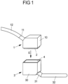
- Fig. 1 shows a schematic view of two connector parts 1, 3 that can be plugged together along a connection direction E.
- Each connector part 1, 3 has a connector housing 10, 30, in which a contact insert 2, 4 with contact elements arranged thereon is received.
- a cable 12, 32 is connected to the connector housing 10, 30 via a cable outlet 11, 31 and is electrically connected within the connector housing 10, 30 to the contact elements of the respectively assigned contact insert 2, 4.
- the present invention can be used not only for connector parts with manually handled connector housings, but can also be used, for example, for connectors provided on electrical systems, for example a control cabinet, in which a contact insert is to be fixed, for example, to a device wall, for example a control cabinet wall.
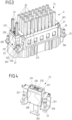
- Each contact insert 2, 4 has a frame part 20, 40 in the form of a rectangular frame, which forms a frame opening 201, 401 into which—in the illustrated embodiment—a contact module 21, 41 is inserted.
- a plug-in section 200, 400 is formed on the frame part 20, 40, wherein the plug-in section 200 of the first contact insert 2 forms a socket into which the plug-in section 400 of the frame part 40 of the other contact insert 4 can be inserted.
- Each contact module 21, 41 has a plurality of plug-in openings 210, 410 into which electrical lines 24 (see Fig. 3 ) for electrical contact with contact elements 211, 411 in the form of contact pins or contact sockets.
- electrical lines 24 see Fig. 3
- the contact elements 211 of one, first contact insert 2 engage with the associated contact elements 411 of the other, second contact insert 4, so that electrical contact is established between the contact inserts 2, 4.
- one or more contact modules can be inserted into the frame opening 201, 401 of each frame part 20, 40, so that individual contact arrangements can be created on the contact inserts 2, 4 to form a customized mating face.
- one contact module 21, 41 is precisely inserted into the frame part 20, 40 and connected to the frame part 20, 40 in a snap-in manner.
- Grounding elements 22, 42 are arranged on both sides of the frame part 20, 40, which, on the one hand, enable mechanical fixing of the contact insert 2, 4 to the associated connector housing 10, 30 via fastening elements 220, 420 and, on the other hand, provide protective contact between the contact inserts 2, 4.
- Each grounding element 22, 42 is supported on the frame part 20, 40 assigned to it via locking sections 221, 421, whereby in this way (if the frame part 20, 40 is made of an electrically conductive material, in particular a metal material), the frame part 20, 40 can also be included in the grounding.
- Contacting lugs 222, 422 extend on the respective associated plug-in section 200, 400 (see Fig. 5B in conjunction with Fig. 2 ) of the earthing elements 22, 42, which run onto each other when the contact inserts 2, 4 are plugged in and thus create an electrical contact between the earthing elements 22, 42 of the two contact inserts 2, 4.
- contacting devices 23', 43' in the form of screw connections for connecting protective lines are provided on the earthing elements 22, 42.
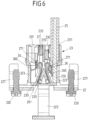
- a contacting device 23 is arranged on a grounding element 22, which contacting device comprises a housing 230 with two plug-in openings 231 for inserting protective lines 25 (see Fig. 6 ) and enables connection of the protective lines 25 by plug-in contact.
- the contacting device 23 has, as can be seen from the sectional view according to Fig. 6 As can be seen, two spring elements 26 are enclosed and held in the housing 230, each of which is assigned to one of the plug-in openings 231. Each spring element 26 has a clamping leg 260, which extends into the area of the plug-in opening 231 assigned to the spring element 26 and serves to lock and contact a protective line 25 inserted into the plug-in opening 231. A holding leg 261 is bent over to form the clamping leg 260 and is enclosed between housing sections 233 of the housing 230, so that the spring element 26 is fixed in the housing 230 via the holding leg 261.
- the clamping leg 260 is movable within the housing 230, undergoing elastic deformation relative to the retaining leg 261.
- a (stripped) wire end 250 of the protective cable 25 presses against the clamping leg 260 and pushes it aside, allowing the wire end 250 to slide past the clamping leg 260 and be elastically pressed against a contacting portion 223 of the grounding element 22 via the end of the clamping leg 260.
- the clamping leg 260 (acting like a barb) locks the protective cable 25 in the plug-in opening 231 when the protective cable 25 is (fully) inserted into the plug-in opening 231 with the wire end 250.
- the protective line 25 is thus held mechanically on the contacting device 23 via the spring element 26 on the one hand and is in planar contact with the contacting section 223 of the earthing element 22 on the other hand due to elastic pressure of the clamping leg 260.
- each plug-in opening 231 is assigned a release element 27, which can be displaced in a release opening 232 of the housing 230 such that, by applying pressure to the release element 27 (e.g., using a tool), the release element 27 slides with a body 270 in the release opening 232 and acts on the clamping leg 260 with an arm 271 protruding from the body 270, so that the latter is pressed out of contact with the wire end 250 of the protective cable 25.
- the protective cable 25 can thus be pulled out of the associated plug-in opening 231.
- Fig. 5A and 5B show a view of the contact insert 2 in the connected state with the contact insert 4 within the connector housing 30 associated with the contact insert 4 (the contact insert 2 is shown without the connector housing 10).
- both contact inserts 2, 4 each have a contacting device 23, 43 on a respective grounding element 22, 42, so that the connection of protective lines 25 in a plug-in manner with a reliable mechanical connection and electrical contact is possible for both contact inserts 2, 4.
- the contacting device 43 on the contact insert 4 is constructed identically to that described above for the contacting device 23 of the contact insert 2.
- the contact lugs 222, 422 of the grounding elements 22, 42 are in contact with one another.
- the contact lugs 222, 422 converge on one another and thus provide electrical contact for the common grounding of the contact inserts 2, 4.
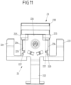
- the earthing element 22, 42 is positively connected to the associated frame part 20, 40 of the contact insert 2, 4, as will be explained below with reference to Fig. 7 to 11 will be explained using an earthing element 22 of the contact insert 2 having a contacting device 23.
- the grounding element 22 has support sections 224 which extend transversely to the plugging direction S and carry the fastening elements 220 for fastening the contact insert 2 in the housing 10 of an associated connector part 1.
- the support sections 224 rest on an end section 205 of the plug-in section 200 of the frame part 20, as can be seen, for example, from Fig. 8 can be seen, and are supported above it in the plugging direction S on the frame part 20.
- the earthing element 22 (with the contacting device 23 arranged thereon) is attached in the plug-in direction S by pushing engagement sections 225 of the earthing element 22, which are bent over to form a wall section 226, in the plug-in direction S into engagement with associated engagement openings 203 on an end face 202 of the frame part 20 in order to thereby establish a positive connection (transverse to the plug-in direction S) between the earthing element 22 and the frame part 20.
- the locking sections 221 which protrude from the support sections 224 counter to the plug-in direction S, snap into engagement with undercuts 204 on the end face 202 of the frame part 20, so that the earthing element 22 is fixed in a locking manner counter to the plug-in direction S on the end face 202 of the frame part 20.
- the earthing element 22 is thus connected to the frame part 20 in a locking manner and is thereby fixed to the frame part 20.
- the contacting device 23 is connected to the grounding element 22 via its housing 230 in a latching and thus form-fitting manner.
- the housing 230 has form-fitting sections 234 on both sides in the form of resilient latching tongues, which engage with the contacting sections 223 of the grounding element 22 when the housing 230 is placed in the plug-in direction S on the grounding element 22, as can be seen from a synopsis of Fig. 7 and Fig. 11 can be seen.
- the form-fitting sections 234 engage in latching openings 227 of the contacting sections 223 and thereby fix the housing 230 (with the spring elements 26 enclosed therein) to the grounding element 22.
- the contacting device 23 can thus be attached to the grounding element 22 in a simple manner by plugging the housing 230 into the grounding element 22 in the plugging direction S.
- the earthing element 22 can also be attached to the frame part 20 in a simple manner - with or without the contacting device 23 arranged thereon - so that the contact insert 2 can be easily installed.
- a grounding element 22 with a contacting device 23 of the type described can be used in particular on existing frame parts 20 without the need to significantly adapt the design of the frame part 20.
- Existing frame parts 20 can thus be equipped with grounding elements 22 and contacting devices 23 arranged thereon and, if necessary, also retrofitted.
- a contacting device for contacting an associated grounding element may have one or more plug-in openings for connecting one or more protective conductors.
- such a contacting device may have only one plug-in opening.
- exactly one contact module is attached to the associated frame part of a contact insert.
Landscapes
- Details Of Connecting Devices For Male And Female Coupling (AREA)
- Connector Housings Or Holding Contact Members (AREA)
Claims (15)
- Insert de contact (2, 4) pour une partie de connecteur enfichable (1, 3), comprenant- une partie de cadre (20) qui présente une portion d'enfichage (200) pour la connexion par enfichage à une partie de connecteur enfichable supplémentaire (3, 1),- au moins un élément de contact électrique (211) disposé au niveau de la portion d'enfichage (200),- un élément de mise à la terre (22) disposé au niveau de la partie de cadre (20), auquel peut être raccordé une ligne de protection (25),- un dispositif de mise en contact (23) disposé au niveau de l'élément de mise à la terre (22), le dispositif de mise en contact (23) présentant un boîtier (230) avec une ouverture d'enfichage (231) pour l'enfichage de la ligne de protection (25) et un élément de ressort (26) disposé au niveau du boîtier (230) pour bloquer la ligne de protection (25) dans l'ouverture d'enfichage (231) and pour mettre en contact la ligne de protection (25) avec l'élément de mise à la terre (22), et- un module de contact (21) disposé au niveau de la partie de cadre (20), le module de contact (21) présentant au moins une ouverture d'enfichage (210) pour l'enfichage d'au moins une ligne électrique (24) dans un direction d'enfichage (S), l'au moins un élément de contact (211) faisant partie du module de contact (21), la partie de cadre (20) présentant une ouverture de cadre (201) dans laquelle est inséré le module de contact (21),caractérisé en ce que l'élément de mise à la terre (22) est disposé à l'extérieur de l'ouverture de cadre (201) au niveau de la partie de cadre (20), l'élément de mise à la terre (22) avec le dispositif de mise en contact (23) disposé au niveau de celui-ci étant fixé à la partie de cadre (20) à l'extérieur de l'ouverture de cadre (201).
- Insert de contact (2, 4) selon la revendication 1, caractérisé en ce que l'élément de ressort (26) présente une branche de serrage (260) qui, lorsque la ligne de protection (25) est enfichée dans l'ouverture d'enfichage (231), est en contact avec la ligne de protection (25).
- Insert de contact (2, 4) selon la revendication 2, caractérisé en ce que la branche de serrage (260) est réalisée de manière à presser la ligne de protection (25) contre une portion de contact (223) de l'élément de mise à la terre (22).
- Insert de contact (2, 4) selon la revendication 2 ou 3, caractérisé en ce que la branche de serrage (260) peut être déplacée par rapport au boîtier (230).
- Insert de contact (2, 4) selon l'une quelconque des revendications 2 à 4, caractérisé en ce que l'élément de ressort (26) présente une branche de retenue (261) par le biais de laquelle l'élément de ressort (26) est retenue sur le boîtier (230).
- Insert de contact (2, 4) selon l'une quelconque des revendications précédentes, caractérisé en ce que le dispositif de mise en contact (23) présente un élément de déverrouillage (27) qui peut être actionné pour déverrouiller la ligne de protection (25) de l'ouverture d'enfichage (231).
- Insert de contact (2, 4) selon la revendication 6, caractérisé en ce que l'élément de déverrouillage (27) présente un bras (271) avec lequel l'élément de déverrouillage (27) agit sur l'élément de ressort (26) lors de l'actionnement.
- Insert de contact (2, 4) selon l'une quelconque des revendications précédentes, caractérisé en ce que le boîtier (230) du dispositif de mise en contact (23) présente deux ouvertures d'enfichage (231) pour l'enfichage de deux lignes de protection (25) et deux éléments de ressort (26) pour le blocage des lignes de protection (25) dans les ouvertures d'enfichage (231).
- Insert de contact (2, 4) selon l'une quelconque des revendications précédentes, caractérisé en ce que l'élément de mise à la terre (22) présente une languette de contact (222, 422) pour établir un contact de mise à la terre avec la partie de connecteur enfichable supplémentaire (3, 1).
- Insert de contact (2, 4) selon l'une quelconque des revendications 1 à 9, caractérisé en ce que la ligne de protection (25) peut être enfichée dans la direction d'enfichage (S) dans l'ouverture d'enfichage (231) du dispositif de mise en contact (23).
- Insert de contact (2, 4) selon l'une quelconque des revendications précédentes, caractérisé en ce que l'élément de mise à la terre (22) est connecté par engagement par correspondance de formes à la partie de cadre (20).
- Insert de contact (2, 4) selon l'une quelconque des revendications précédentes, caractérisé en ce que l'élément de mise à la terre (22) présente une portion d'engagement (225) qui est enfoncée pour la connexion dans une ouverture d'engagement (203) de la partie de cadre (20), et/ou une portion d'encliquetage (221) par le biais de laquelle l'élément de mise à la terre (22) est encliquetée avec la partie de cadre (20).
- Insert de contact (2, 4) selon l'une quelconque des revendications précédentes, caractérisé en ce que le boîtier (230) du dispositif de mise en contact (23) est connecté par engagement par correspondance de formes avec l'élément de mise à la terre (22).
- Insert de contact (2, 4) selon l'une quelconque des revendications précédentes, caractérisé en ce que le boîtier (230) du dispositif de mise en contact (23) présente une portion d'engagement par correspondance de formes (234) par le biais de laquelle le boîtier (230) est encliquetée avec l'élément de mise à la terre (22).
- Partie de connecteur enfichable (1, 3) comprenant un insert de contact (2, 4) selon l'une quelconque des revendications précédentes.
Applications Claiming Priority (1)
| Application Number | Priority Date | Filing Date | Title |
|---|---|---|---|
| DE102016120002.6A DE102016120002A1 (de) | 2016-10-20 | 2016-10-20 | Kontakteinsatz für ein Steckverbinderteil |
Publications (3)
| Publication Number | Publication Date |
|---|---|
| EP3312940A1 EP3312940A1 (fr) | 2018-04-25 |
| EP3312940B1 EP3312940B1 (fr) | 2020-01-15 |
| EP3312940B2 true EP3312940B2 (fr) | 2025-04-30 |
Family
ID=60043061
Family Applications (1)
| Application Number | Title | Priority Date | Filing Date |
|---|---|---|---|
| EP17195383.9A Active EP3312940B2 (fr) | 2016-10-20 | 2017-10-09 | Insert de contacts pour une partie de connecteur |
Country Status (3)
| Country | Link |
|---|---|
| EP (1) | EP3312940B2 (fr) |
| CN (1) | CN107968297B (fr) |
| DE (2) | DE102016120002A1 (fr) |
Families Citing this family (14)
| Publication number | Priority date | Publication date | Assignee | Title |
|---|---|---|---|---|
| DE102017106720A1 (de) | 2017-03-29 | 2018-10-04 | Phoenix Contact Gmbh & Co. Kg | Kompakte Leiteranschlussklemme |
| DE102017108162A1 (de) * | 2017-04-18 | 2018-10-18 | Phoenix Contact Gmbh & Co. Kg | Baugruppe für ein Steckverbinderteil mit einem Kontakteinsatz und einem Erdungselement |
| US11450989B2 (en) | 2018-09-13 | 2022-09-20 | Harting Electric Stiftung & Co. Kg | Plug-in connector with ground terminal region |
| DE102018126615A1 (de) * | 2018-10-25 | 2020-04-30 | Phoenix Contact E-Mobility Gmbh | Steckverbinder mit einem elektrischen Verbindungselement für mehrere Schirmleiter |
| DE102018133135A1 (de) * | 2018-12-20 | 2020-06-25 | Phoenix Contact Gmbh & Co. Kg | Halterahmen für einen Steckverbinder |
| DE102019103772B4 (de) * | 2019-02-13 | 2024-05-23 | Harting Electric Stiftung & Co. Kg | Schutzleiteranschluss |
| DE102019104704A1 (de) | 2019-02-25 | 2020-08-27 | Harting Electric Gmbh & Co. Kg | Anschlusseinrichtung für elektrische Leiter |
| DE102019132167A1 (de) * | 2019-11-27 | 2021-05-27 | Connaught Electronics Ltd. | Elektrischer Stecker zum Anschluss an eine Fahrzeugkamera, sowie Anordnung |
| DE102019135726A1 (de) * | 2019-12-23 | 2021-06-24 | Phoenix Contact Gmbh & Co. Kg | Halterahmen für einen Steckverbinder |
| LU102017B1 (de) * | 2020-08-25 | 2022-02-25 | Phoenix Contact Gmbh & Co | Potentialverteileranordnung |
| CN114914739A (zh) * | 2021-02-09 | 2022-08-16 | 哈廷电子有限公司及两合公司 | 用于连接器的嵌件 |
| CN118943792A (zh) * | 2023-05-09 | 2024-11-12 | 哈廷电子基金会两合公司 | 推入式嵌件及包括其的连接器 |
| DE102024113595A1 (de) * | 2024-05-15 | 2025-11-20 | Harting Electric Stiftung & Co. Kg | Erdungsmodul für einen modularen Industriesteckverbinder |
| WO2025252280A1 (fr) * | 2024-06-05 | 2025-12-11 | Harting Electric Stiftung & Co. Kg | Plaque de mise à la terre de protection enfichable, insert enfichable et son procédé d'assemblage |
Citations (12)
| Publication number | Priority date | Publication date | Assignee | Title |
|---|---|---|---|---|
| DE8111418U1 (de) † | 1981-04-15 | 1981-11-05 | Harting Elektronik Gmbh, 4992 Espelkamp | Anschlußverteiler |
| US5478259A (en) † | 1994-03-28 | 1995-12-26 | Burndy Corporation | Card edge connector with combined shielding and voltage drain protection |
| DE202006009460U1 (de) † | 2005-10-29 | 2007-03-15 | Weidmüller Interface GmbH & Co. KG | Anschlussvorrichtung für Leiter |
| DE102007013536B3 (de) † | 2007-03-18 | 2008-10-02 | Phoenix Contact Gmbh & Co. Kg | PE-Anschluss für Steckverbinder |
| DE202010008028U1 (de) † | 2009-07-18 | 2010-12-30 | Weidmüller Interface GmbH & Co. KG | Anschlussvorrichtung für Leiter |
| WO2011069522A1 (fr) † | 2009-12-09 | 2011-06-16 | Harting Electric Gmbh & Co. Kg | Connecteur de système |
| DE102011115637A1 (de) † | 2011-06-21 | 2012-12-27 | Phoenix Contact Gmbh & Co. Kg | Elektrische Anschlussklemme |
| EP2544314A2 (fr) † | 2010-02-22 | 2013-01-09 | Tyco Electronics AMP GmbH | Moyens de contact pour fixer l'extrémité d'un câble |
| DE102010017717B4 (de) † | 2010-07-02 | 2014-06-05 | Phoenix Contact Gmbh & Co. Kg | Steckverbinder |
| DE102013108383A1 (de) † | 2013-08-05 | 2015-02-05 | Harting Electric Gmbh & Co. Kg | Steckverbindermodul |
| WO2015091098A1 (fr) † | 2013-12-17 | 2015-06-25 | Eaton Electrical Ip Gmbh & Co. Kg | Système composé d'un boîtier électronique et d'un agencement de contact de protection |
| DE202014010621U1 (de) † | 2014-10-16 | 2016-02-11 | Harting Electric Gmbh & Co. Kg | Steckverbinder |
Family Cites Families (11)
| Publication number | Priority date | Publication date | Assignee | Title |
|---|---|---|---|---|
| DE29505272U1 (de) * | 1995-03-29 | 1995-07-20 | Phoenix Contact Gmbh & Co., 32825 Blomberg | Sensor-Aktor-Verteiler |
| DE29520008U1 (de) | 1995-12-16 | 1996-03-07 | Harting Elektronik Gmbh, 32339 Espelkamp | Elektrischer Steckverbinder |
| DE29602740U1 (de) | 1996-02-21 | 1996-04-11 | Phoenix Contact GmbH & Co, 32825 Blomberg | Elektrischer Steckverbinder |
| DE10325009B4 (de) * | 2002-08-21 | 2004-09-16 | Ges Electronic & Service Gmbh | Modularer Steckverbinder und dessen Verwendung |
| DE20300266U1 (de) * | 2003-01-08 | 2004-05-19 | Bals Elektrotechnik Gmbh & Co. Kg | Leiteranschlussklemme, insbesondere für Steckverbinder |
| JP2004319196A (ja) * | 2003-04-15 | 2004-11-11 | Auto Network Gijutsu Kenkyusho:Kk | シールド接続構造 |
| DE20308863U1 (de) * | 2003-06-06 | 2003-08-21 | Ria Btr Produktions Gmbh | Anschlussklemme |
| DE102006004238B4 (de) * | 2005-01-28 | 2011-09-29 | Amphenol-Tuchel Electronics Gmbh | Steckverbinder |
| DE202005015465U1 (de) * | 2005-10-01 | 2007-02-15 | Weidmüller Interface GmbH & Co. KG | Steckverbindersystem aus schweren elektrischen Steckverbindern |
| FR2936659B1 (fr) * | 2008-09-29 | 2010-11-12 | Legrand France | Broche electrique integrant la cage d'une borne de connexion electrique automatique |
| JP5313805B2 (ja) * | 2009-08-07 | 2013-10-09 | スリーエム イノベイティブ プロパティズ カンパニー | フローティングコネクタ |
-
2016
- 2016-10-20 DE DE102016120002.6A patent/DE102016120002A1/de active Pending
-
2017
- 2017-10-09 DE DE202017007056.1U patent/DE202017007056U1/de active Active
- 2017-10-09 EP EP17195383.9A patent/EP3312940B2/fr active Active
- 2017-10-20 CN CN201711007454.1A patent/CN107968297B/zh active Active
Patent Citations (12)
| Publication number | Priority date | Publication date | Assignee | Title |
|---|---|---|---|---|
| DE8111418U1 (de) † | 1981-04-15 | 1981-11-05 | Harting Elektronik Gmbh, 4992 Espelkamp | Anschlußverteiler |
| US5478259A (en) † | 1994-03-28 | 1995-12-26 | Burndy Corporation | Card edge connector with combined shielding and voltage drain protection |
| DE202006009460U1 (de) † | 2005-10-29 | 2007-03-15 | Weidmüller Interface GmbH & Co. KG | Anschlussvorrichtung für Leiter |
| DE102007013536B3 (de) † | 2007-03-18 | 2008-10-02 | Phoenix Contact Gmbh & Co. Kg | PE-Anschluss für Steckverbinder |
| DE202010008028U1 (de) † | 2009-07-18 | 2010-12-30 | Weidmüller Interface GmbH & Co. KG | Anschlussvorrichtung für Leiter |
| WO2011069522A1 (fr) † | 2009-12-09 | 2011-06-16 | Harting Electric Gmbh & Co. Kg | Connecteur de système |
| EP2544314A2 (fr) † | 2010-02-22 | 2013-01-09 | Tyco Electronics AMP GmbH | Moyens de contact pour fixer l'extrémité d'un câble |
| DE102010017717B4 (de) † | 2010-07-02 | 2014-06-05 | Phoenix Contact Gmbh & Co. Kg | Steckverbinder |
| DE102011115637A1 (de) † | 2011-06-21 | 2012-12-27 | Phoenix Contact Gmbh & Co. Kg | Elektrische Anschlussklemme |
| DE102013108383A1 (de) † | 2013-08-05 | 2015-02-05 | Harting Electric Gmbh & Co. Kg | Steckverbindermodul |
| WO2015091098A1 (fr) † | 2013-12-17 | 2015-06-25 | Eaton Electrical Ip Gmbh & Co. Kg | Système composé d'un boîtier électronique et d'un agencement de contact de protection |
| DE202014010621U1 (de) † | 2014-10-16 | 2016-02-11 | Harting Electric Gmbh & Co. Kg | Steckverbinder |
Also Published As
| Publication number | Publication date |
|---|---|
| CN107968297A (zh) | 2018-04-27 |
| DE202017007056U1 (de) | 2019-05-02 |
| EP3312940A1 (fr) | 2018-04-25 |
| EP3312940B1 (fr) | 2020-01-15 |
| DE102016120002A1 (de) | 2018-04-26 |
| CN107968297B (zh) | 2020-03-17 |
Similar Documents
| Publication | Publication Date | Title |
|---|---|---|
| EP3312940B2 (fr) | Insert de contacts pour une partie de connecteur | |
| EP3613110B1 (fr) | Assemblage d'une pièce de connecteur à fiches avec insert de contact et élément de mise à la terre | |
| DE102015114186A1 (de) | Elektrische Reihenklemme | |
| EP3593411B1 (fr) | Insert de contact pour partie connecteur enfichable | |
| EP2497169A2 (fr) | Agencement de montage pour appareils électriques | |
| DE202017107035U1 (de) | Steckverbinderteil mit einem PE-Anschluss | |
| EP3446371B1 (fr) | Un connecteur électrique avec des contacts modulaires insérées dans un cadre de fixation | |
| DE102016121966A1 (de) | Kontakteinsatz für ein Steckverbinderteil | |
| DE102017105077B4 (de) | Kontakteinsatz für ein Steckverbinderteil | |
| DE102010033112B4 (de) | Elektroinstallationsgerät | |
| DE202017101365U1 (de) | Kontakteinsatz für ein Steckverbinderteil | |
| DE102020119128A1 (de) | Steckverbindermodul zum Anschließen einer Schutzleitung | |
| DE10005260A1 (de) | Isoliergehäuse für Verteilerklemme | |
| DE29602268U1 (de) | Geschirmte Leiterplattensteckbuchse | |
| DE2139701C3 (de) | Elektronische Anlage mit einem Rahmen zur Aufnahme von steckbaren Karten mit gedruckten Schaltungen | |
| EP3625854B1 (fr) | Ensemble avec deux dispositifs de connexion et une borne à goujon fileté | |
| DE102015110223A1 (de) | Baugruppe einer Klemmeneinrichtung zum Anschließen von elektrischen Leitern | |
| LU100001B1 (de) | Steckverbinderteil mit einem PE-Anschluss | |
| DE202013104941U1 (de) | Elektrische Steckverbinderanordnung und Schirmanbindungselement hierzu | |
| LU505385B1 (de) | Baukastensystem zum Herstellen eines Frontsteckers | |
| EP2920852A1 (fr) | Insert de prise | |
| EP2262062B1 (fr) | Connecteur à fiches | |
| DE10331441A1 (de) | Kontakteinsatz zum Anschließen der Leiter eines mehradrigen Kabels und elektrisches Gerät | |
| DE19619323A1 (de) | Elektrische Steckverbindung | |
| DE102020119130A1 (de) | Steckverbindermodul zum Anschließen einer elektrischen Leitung |
Legal Events
| Date | Code | Title | Description |
|---|---|---|---|
| REG | Reference to a national code |
Ref country code: DE Ref legal event code: R138 Ref document number: 202017007056 Country of ref document: DE Free format text: GERMAN DOCUMENT NUMBER IS 502017003505 |
|
| PUAI | Public reference made under article 153(3) epc to a published international application that has entered the european phase |
Free format text: ORIGINAL CODE: 0009012 |
|
| STAA | Information on the status of an ep patent application or granted ep patent |
Free format text: STATUS: THE APPLICATION HAS BEEN PUBLISHED |
|
| AK | Designated contracting states |
Kind code of ref document: A1 Designated state(s): AL AT BE BG CH CY CZ DE DK EE ES FI FR GB GR HR HU IE IS IT LI LT LU LV MC MK MT NL NO PL PT RO RS SE SI SK SM TR |
|
| AX | Request for extension of the european patent |
Extension state: BA ME |
|
| STAA | Information on the status of an ep patent application or granted ep patent |
Free format text: STATUS: REQUEST FOR EXAMINATION WAS MADE |
|
| 17P | Request for examination filed |
Effective date: 20180921 |
|
| RBV | Designated contracting states (corrected) |
Designated state(s): AL AT BE BG CH CY CZ DE DK EE ES FI FR GB GR HR HU IE IS IT LI LT LU LV MC MK MT NL NO PL PT RO RS SE SI SK SM TR |
|
| TPAC | Observations filed by third parties |
Free format text: ORIGINAL CODE: EPIDOSNTIPA |
|
| STAA | Information on the status of an ep patent application or granted ep patent |
Free format text: STATUS: EXAMINATION IS IN PROGRESS |
|
| 17Q | First examination report despatched |
Effective date: 20190411 |
|
| GRAP | Despatch of communication of intention to grant a patent |
Free format text: ORIGINAL CODE: EPIDOSNIGR1 |
|
| STAA | Information on the status of an ep patent application or granted ep patent |
Free format text: STATUS: GRANT OF PATENT IS INTENDED |
|
| INTG | Intention to grant announced |
Effective date: 20190917 |
|
| GRAS | Grant fee paid |
Free format text: ORIGINAL CODE: EPIDOSNIGR3 |
|
| GRAA | (expected) grant |
Free format text: ORIGINAL CODE: 0009210 |
|
| STAA | Information on the status of an ep patent application or granted ep patent |
Free format text: STATUS: THE PATENT HAS BEEN GRANTED |
|
| AK | Designated contracting states |
Kind code of ref document: B1 Designated state(s): AL AT BE BG CH CY CZ DE DK EE ES FI FR GB GR HR HU IE IS IT LI LT LU LV MC MK MT NL NO PL PT RO RS SE SI SK SM TR |
|
| REG | Reference to a national code |
Ref country code: CH Ref legal event code: EP Ref country code: GB Ref legal event code: FG4D Free format text: NOT ENGLISH |
|
| REG | Reference to a national code |
Ref country code: IE Ref legal event code: FG4D Free format text: LANGUAGE OF EP DOCUMENT: GERMAN |
|
| REG | Reference to a national code |
Ref country code: AT Ref legal event code: REF Ref document number: 1225989 Country of ref document: AT Kind code of ref document: T Effective date: 20200215 |
|
| REG | Reference to a national code |
Ref country code: DE Ref legal event code: R096 Ref document number: 502017003505 Country of ref document: DE |
|
| REG | Reference to a national code |
Ref country code: NL Ref legal event code: MP Effective date: 20200115 |
|
| REG | Reference to a national code |
Ref country code: LT Ref legal event code: MG4D |
|
| PG25 | Lapsed in a contracting state [announced via postgrant information from national office to epo] |
Ref country code: NO Free format text: LAPSE BECAUSE OF FAILURE TO SUBMIT A TRANSLATION OF THE DESCRIPTION OR TO PAY THE FEE WITHIN THE PRESCRIBED TIME-LIMIT Effective date: 20200415 Ref country code: PT Free format text: LAPSE BECAUSE OF FAILURE TO SUBMIT A TRANSLATION OF THE DESCRIPTION OR TO PAY THE FEE WITHIN THE PRESCRIBED TIME-LIMIT Effective date: 20200607 Ref country code: FI Free format text: LAPSE BECAUSE OF FAILURE TO SUBMIT A TRANSLATION OF THE DESCRIPTION OR TO PAY THE FEE WITHIN THE PRESCRIBED TIME-LIMIT Effective date: 20200115 Ref country code: RS Free format text: LAPSE BECAUSE OF FAILURE TO SUBMIT A TRANSLATION OF THE DESCRIPTION OR TO PAY THE FEE WITHIN THE PRESCRIBED TIME-LIMIT Effective date: 20200115 Ref country code: NL Free format text: LAPSE BECAUSE OF FAILURE TO SUBMIT A TRANSLATION OF THE DESCRIPTION OR TO PAY THE FEE WITHIN THE PRESCRIBED TIME-LIMIT Effective date: 20200115 |
|
| PG25 | Lapsed in a contracting state [announced via postgrant information from national office to epo] |
Ref country code: GR Free format text: LAPSE BECAUSE OF FAILURE TO SUBMIT A TRANSLATION OF THE DESCRIPTION OR TO PAY THE FEE WITHIN THE PRESCRIBED TIME-LIMIT Effective date: 20200416 Ref country code: IS Free format text: LAPSE BECAUSE OF FAILURE TO SUBMIT A TRANSLATION OF THE DESCRIPTION OR TO PAY THE FEE WITHIN THE PRESCRIBED TIME-LIMIT Effective date: 20200515 Ref country code: BG Free format text: LAPSE BECAUSE OF FAILURE TO SUBMIT A TRANSLATION OF THE DESCRIPTION OR TO PAY THE FEE WITHIN THE PRESCRIBED TIME-LIMIT Effective date: 20200415 Ref country code: LV Free format text: LAPSE BECAUSE OF FAILURE TO SUBMIT A TRANSLATION OF THE DESCRIPTION OR TO PAY THE FEE WITHIN THE PRESCRIBED TIME-LIMIT Effective date: 20200115 Ref country code: SE Free format text: LAPSE BECAUSE OF FAILURE TO SUBMIT A TRANSLATION OF THE DESCRIPTION OR TO PAY THE FEE WITHIN THE PRESCRIBED TIME-LIMIT Effective date: 20200115 Ref country code: HR Free format text: LAPSE BECAUSE OF FAILURE TO SUBMIT A TRANSLATION OF THE DESCRIPTION OR TO PAY THE FEE WITHIN THE PRESCRIBED TIME-LIMIT Effective date: 20200115 |
|
| REG | Reference to a national code |
Ref country code: DE Ref legal event code: R026 Ref document number: 502017003505 Country of ref document: DE |
|
| PLBI | Opposition filed |
Free format text: ORIGINAL CODE: 0009260 |
|
| PLAX | Notice of opposition and request to file observation + time limit sent |
Free format text: ORIGINAL CODE: EPIDOSNOBS2 |
|
| PG25 | Lapsed in a contracting state [announced via postgrant information from national office to epo] |
Ref country code: ES Free format text: LAPSE BECAUSE OF FAILURE TO SUBMIT A TRANSLATION OF THE DESCRIPTION OR TO PAY THE FEE WITHIN THE PRESCRIBED TIME-LIMIT Effective date: 20200115 Ref country code: DK Free format text: LAPSE BECAUSE OF FAILURE TO SUBMIT A TRANSLATION OF THE DESCRIPTION OR TO PAY THE FEE WITHIN THE PRESCRIBED TIME-LIMIT Effective date: 20200115 Ref country code: SK Free format text: LAPSE BECAUSE OF FAILURE TO SUBMIT A TRANSLATION OF THE DESCRIPTION OR TO PAY THE FEE WITHIN THE PRESCRIBED TIME-LIMIT Effective date: 20200115 Ref country code: SM Free format text: LAPSE BECAUSE OF FAILURE TO SUBMIT A TRANSLATION OF THE DESCRIPTION OR TO PAY THE FEE WITHIN THE PRESCRIBED TIME-LIMIT Effective date: 20200115 Ref country code: EE Free format text: LAPSE BECAUSE OF FAILURE TO SUBMIT A TRANSLATION OF THE DESCRIPTION OR TO PAY THE FEE WITHIN THE PRESCRIBED TIME-LIMIT Effective date: 20200115 Ref country code: CZ Free format text: LAPSE BECAUSE OF FAILURE TO SUBMIT A TRANSLATION OF THE DESCRIPTION OR TO PAY THE FEE WITHIN THE PRESCRIBED TIME-LIMIT Effective date: 20200115 Ref country code: LT Free format text: LAPSE BECAUSE OF FAILURE TO SUBMIT A TRANSLATION OF THE DESCRIPTION OR TO PAY THE FEE WITHIN THE PRESCRIBED TIME-LIMIT Effective date: 20200115 Ref country code: RO Free format text: LAPSE BECAUSE OF FAILURE TO SUBMIT A TRANSLATION OF THE DESCRIPTION OR TO PAY THE FEE WITHIN THE PRESCRIBED TIME-LIMIT Effective date: 20200115 |
|
| 26 | Opposition filed |
Opponent name: HARTING ELECTRIC GMBH & CO. KG Effective date: 20201012 |
|
| PG25 | Lapsed in a contracting state [announced via postgrant information from national office to epo] |
Ref country code: PL Free format text: LAPSE BECAUSE OF FAILURE TO SUBMIT A TRANSLATION OF THE DESCRIPTION OR TO PAY THE FEE WITHIN THE PRESCRIBED TIME-LIMIT Effective date: 20200115 Ref country code: SI Free format text: LAPSE BECAUSE OF FAILURE TO SUBMIT A TRANSLATION OF THE DESCRIPTION OR TO PAY THE FEE WITHIN THE PRESCRIBED TIME-LIMIT Effective date: 20200115 |
|
| PLBB | Reply of patent proprietor to notice(s) of opposition received |
Free format text: ORIGINAL CODE: EPIDOSNOBS3 |
|
| REG | Reference to a national code |
Ref country code: CH Ref legal event code: PL |
|
| PG25 | Lapsed in a contracting state [announced via postgrant information from national office to epo] |
Ref country code: LU Free format text: LAPSE BECAUSE OF NON-PAYMENT OF DUE FEES Effective date: 20201009 Ref country code: MC Free format text: LAPSE BECAUSE OF FAILURE TO SUBMIT A TRANSLATION OF THE DESCRIPTION OR TO PAY THE FEE WITHIN THE PRESCRIBED TIME-LIMIT Effective date: 20200115 |
|
| REG | Reference to a national code |
Ref country code: BE Ref legal event code: MM Effective date: 20201031 |
|
| PG25 | Lapsed in a contracting state [announced via postgrant information from national office to epo] |
Ref country code: LI Free format text: LAPSE BECAUSE OF NON-PAYMENT OF DUE FEES Effective date: 20201031 Ref country code: CH Free format text: LAPSE BECAUSE OF NON-PAYMENT OF DUE FEES Effective date: 20201031 Ref country code: BE Free format text: LAPSE BECAUSE OF NON-PAYMENT OF DUE FEES Effective date: 20201031 |
|
| PG25 | Lapsed in a contracting state [announced via postgrant information from national office to epo] |
Ref country code: IE Free format text: LAPSE BECAUSE OF NON-PAYMENT OF DUE FEES Effective date: 20201009 |
|
| PG25 | Lapsed in a contracting state [announced via postgrant information from national office to epo] |
Ref country code: TR Free format text: LAPSE BECAUSE OF FAILURE TO SUBMIT A TRANSLATION OF THE DESCRIPTION OR TO PAY THE FEE WITHIN THE PRESCRIBED TIME-LIMIT Effective date: 20200115 Ref country code: MT Free format text: LAPSE BECAUSE OF FAILURE TO SUBMIT A TRANSLATION OF THE DESCRIPTION OR TO PAY THE FEE WITHIN THE PRESCRIBED TIME-LIMIT Effective date: 20200115 Ref country code: CY Free format text: LAPSE BECAUSE OF FAILURE TO SUBMIT A TRANSLATION OF THE DESCRIPTION OR TO PAY THE FEE WITHIN THE PRESCRIBED TIME-LIMIT Effective date: 20200115 |
|
| GBPC | Gb: european patent ceased through non-payment of renewal fee |
Effective date: 20211009 |
|
| PG25 | Lapsed in a contracting state [announced via postgrant information from national office to epo] |
Ref country code: MK Free format text: LAPSE BECAUSE OF FAILURE TO SUBMIT A TRANSLATION OF THE DESCRIPTION OR TO PAY THE FEE WITHIN THE PRESCRIBED TIME-LIMIT Effective date: 20200115 Ref country code: AL Free format text: LAPSE BECAUSE OF FAILURE TO SUBMIT A TRANSLATION OF THE DESCRIPTION OR TO PAY THE FEE WITHIN THE PRESCRIBED TIME-LIMIT Effective date: 20200115 |
|
| APBM | Appeal reference recorded |
Free format text: ORIGINAL CODE: EPIDOSNREFNO |
|
| APBP | Date of receipt of notice of appeal recorded |
Free format text: ORIGINAL CODE: EPIDOSNNOA2O |
|
| PLAB | Opposition data, opponent's data or that of the opponent's representative modified |
Free format text: ORIGINAL CODE: 0009299OPPO |
|
| PG25 | Lapsed in a contracting state [announced via postgrant information from national office to epo] |
Ref country code: GB Free format text: LAPSE BECAUSE OF NON-PAYMENT OF DUE FEES Effective date: 20211009 |
|
| APAH | Appeal reference modified |
Free format text: ORIGINAL CODE: EPIDOSCREFNO |
|
| R26 | Opposition filed (corrected) |
Opponent name: HARTING ELECTRIC STIFTUNG & CO. KG Effective date: 20201012 |
|
| APBQ | Date of receipt of statement of grounds of appeal recorded |
Free format text: ORIGINAL CODE: EPIDOSNNOA3O |
|
| P01 | Opt-out of the competence of the unified patent court (upc) registered |
Effective date: 20230424 |
|
| REG | Reference to a national code |
Ref country code: AT Ref legal event code: MM01 Ref document number: 1225989 Country of ref document: AT Kind code of ref document: T Effective date: 20221009 |
|
| PG25 | Lapsed in a contracting state [announced via postgrant information from national office to epo] |
Ref country code: AT Free format text: LAPSE BECAUSE OF NON-PAYMENT OF DUE FEES Effective date: 20221009 |
|
| APAH | Appeal reference modified |
Free format text: ORIGINAL CODE: EPIDOSCREFNO |
|
| APAH | Appeal reference modified |
Free format text: ORIGINAL CODE: EPIDOSCREFNO |
|
| APBU | Appeal procedure closed |
Free format text: ORIGINAL CODE: EPIDOSNNOA9O |
|
| PGFP | Annual fee paid to national office [announced via postgrant information from national office to epo] |
Ref country code: FR Payment date: 20241025 Year of fee payment: 8 |
|
| PGFP | Annual fee paid to national office [announced via postgrant information from national office to epo] |
Ref country code: IT Payment date: 20241022 Year of fee payment: 8 |
|
| PUAH | Patent maintained in amended form |
Free format text: ORIGINAL CODE: 0009272 |
|
| STAA | Information on the status of an ep patent application or granted ep patent |
Free format text: STATUS: PATENT MAINTAINED AS AMENDED |
|
| PGFP | Annual fee paid to national office [announced via postgrant information from national office to epo] |
Ref country code: DE Payment date: 20241227 Year of fee payment: 8 |
|
| 27A | Patent maintained in amended form |
Effective date: 20250430 |
|
| AK | Designated contracting states |
Kind code of ref document: B2 Designated state(s): AL AT BE BG CH CY CZ DE DK EE ES FI FR GB GR HR HU IE IS IT LI LT LU LV MC MK MT NL NO PL PT RO RS SE SI SK SM TR |
|
| REG | Reference to a national code |
Ref country code: DE Ref legal event code: R102 Ref document number: 502017003505 Country of ref document: DE |