EP3312940B2 - Contact insert for a connector part - Google Patents
Contact insert for a connector part Download PDFInfo
- Publication number
- EP3312940B2 EP3312940B2 EP17195383.9A EP17195383A EP3312940B2 EP 3312940 B2 EP3312940 B2 EP 3312940B2 EP 17195383 A EP17195383 A EP 17195383A EP 3312940 B2 EP3312940 B2 EP 3312940B2
- Authority
- EP
- European Patent Office
- Prior art keywords
- contact
- plug
- frame part
- housing
- protective
- Prior art date
- Legal status (The legal status is an assumption and is not a legal conclusion. Google has not performed a legal analysis and makes no representation as to the accuracy of the status listed.)
- Active
Links
Images


Classifications
-
- H—ELECTRICITY
- H01—ELECTRIC ELEMENTS
- H01R—ELECTRICALLY-CONDUCTIVE CONNECTIONS; STRUCTURAL ASSOCIATIONS OF A PLURALITY OF MUTUALLY-INSULATED ELECTRICAL CONNECTING ELEMENTS; COUPLING DEVICES; CURRENT COLLECTORS
- H01R13/00—Details of coupling devices of the kinds covered by groups H01R12/70 or H01R24/00 - H01R33/00
- H01R13/648—Protective earth or shield arrangements on coupling devices, e.g. anti-static shielding
-
- H—ELECTRICITY
- H01—ELECTRIC ELEMENTS
- H01R—ELECTRICALLY-CONDUCTIVE CONNECTIONS; STRUCTURAL ASSOCIATIONS OF A PLURALITY OF MUTUALLY-INSULATED ELECTRICAL CONNECTING ELEMENTS; COUPLING DEVICES; CURRENT COLLECTORS
- H01R13/00—Details of coupling devices of the kinds covered by groups H01R12/70 or H01R24/00 - H01R33/00
- H01R13/46—Bases; Cases
- H01R13/514—Bases; Cases composed as a modular blocks or assembly, i.e. composed of co-operating parts provided with contact members or holding contact members between them
-
- H—ELECTRICITY
- H01—ELECTRIC ELEMENTS
- H01R—ELECTRICALLY-CONDUCTIVE CONNECTIONS; STRUCTURAL ASSOCIATIONS OF A PLURALITY OF MUTUALLY-INSULATED ELECTRICAL CONNECTING ELEMENTS; COUPLING DEVICES; CURRENT COLLECTORS
- H01R13/00—Details of coupling devices of the kinds covered by groups H01R12/70 or H01R24/00 - H01R33/00
- H01R13/46—Bases; Cases
- H01R13/516—Means for holding or embracing insulating body, e.g. casing, hoods
- H01R13/518—Means for holding or embracing insulating body, e.g. casing, hoods for holding or embracing several coupling parts, e.g. frames
-
- H—ELECTRICITY
- H01—ELECTRIC ELEMENTS
- H01R—ELECTRICALLY-CONDUCTIVE CONNECTIONS; STRUCTURAL ASSOCIATIONS OF A PLURALITY OF MUTUALLY-INSULATED ELECTRICAL CONNECTING ELEMENTS; COUPLING DEVICES; CURRENT COLLECTORS
- H01R13/00—Details of coupling devices of the kinds covered by groups H01R12/70 or H01R24/00 - H01R33/00
- H01R13/648—Protective earth or shield arrangements on coupling devices, e.g. anti-static shielding
- H01R13/655—Protective earth or shield arrangements on coupling devices, e.g. anti-static shielding with earth brace
-
- H—ELECTRICITY
- H01—ELECTRIC ELEMENTS
- H01R—ELECTRICALLY-CONDUCTIVE CONNECTIONS; STRUCTURAL ASSOCIATIONS OF A PLURALITY OF MUTUALLY-INSULATED ELECTRICAL CONNECTING ELEMENTS; COUPLING DEVICES; CURRENT COLLECTORS
- H01R4/00—Electrically-conductive connections between two or more conductive members in direct contact, i.e. touching one another; Means for effecting or maintaining such contact; Electrically-conductive connections having two or more spaced connecting locations for conductors and using contact members penetrating insulation
- H01R4/28—Clamped connections, spring connections
- H01R4/48—Clamped connections, spring connections utilising a spring, clip, or other resilient member
Definitions
- the invention relates to a contact insert for a connector part according to the preamble of claim 1.
- Such a contact insert comprises a frame part which has a plug-in section for plugging into another plug-in connector part, at least one electrical contact element arranged on the plug-in section and an earthing element arranged on the frame part to which a protective line can be connected.
- a connector insert has several rows of contact elements.
- the contact insert can be inserted into a bulkhead housing that is attached to a mounting wall.
- PE metal part A grounding element (referred to as PE metal part) which is used to fasten a contact insert, for example in a plug housing, and has a so-called PE screw connection for connecting a protective line.
- a contact insert with a frame part and a contact module insertable therein is known.
- a connection device for connecting a protective conductor is arranged on the frame part, which has a connection arm with a screw connection.
- a variety of contact modules can be inserted into a frame part known as a mounting frame. Some of the modules can also be used to connect protective conductors for so-called PE contacting (PE stands for "protective earth”). These contact modules are designed as screw connections.
- DE 295 05 272 U1 discloses a sensor-actuator distributor with a distributor housing in which a circuit board is arranged, on which a plug part is arranged. The plug part can be connected to a connector plug.
- DE 10 2013 108 383 discloses a connector module in whose housing an electrical contact is accommodated to which an earth connection can be applied.
- JP 2004 319196 A discloses a contact device for shielded cable.
- the contact insert has a Contacting device which has a housing with a plug-in opening for inserting the protective line and a spring element arranged on the housing for locking the protective line in the plug-in opening and for contacting the protective line with the earthing element.
- Such a grounding element can be detachably mounted on a frame part of a contact insert with a contacting device arranged thereon. This can, if necessary, enable the contact insert to be equipped with a grounding element and a contacting device arranged thereon without having to adapt the design of the frame part. Such a grounding element with a contacting device arranged thereon can thus be used on an existing frame part and, if necessary, even retrofitted.
- the protective cable is connected to the grounding element on the frame part via a spring-loaded connection.
- the protective cable can be easily and conveniently inserted with a (stripped) wire end into the plug-in opening of the contacting device housing. It is inserted and thus reaches the area of the spring element, which locks the protective cable in the housing and ensures contact between the protective cable and the grounding element. Therefore, connection requires (only) plugging in the protective cable.
- the locking and contact of the protective cable with the grounding element can advantageously occur automatically, without the need for further operating steps to secure the protective cable to the grounding element.
- the spring element has a clamping leg that engages the protective cable when inserted into the plug-in opening.
- the protective cable is locked in the housing of the contacting device via the clamping leg.
- the clamping leg is configured, for example, to press the protective cable against a contact section of the grounding element, thus bringing the protective cable into electrical contact with the grounding element.
- the protective cable When the protective cable is inserted into the plug-in opening of the housing, the protective cable acts on the clamping leg of the spring element and deflects it, preferably elastically, in such a way that the protective cable is locked in the housing and contacted with the grounding element.
- the clamping leg is movably arranged within the housing.
- the spring element in one embodiment, has a retaining leg, via which the spring element is held to the housing.
- the retaining leg can, for example, be bent over to form the clamping leg and secured between housing sections of the housing in such a way that the spring element is attached to the housing via the retaining leg.
- the connection between the protective cable and the contacting device is preferably detachable.
- the contacting device can, for example, have a release element that can be actuated to release the protective cable and, for example, has an arm with which the release element acts on the spring element when actuated.
- the release element can, for example, be actuated using a tool, such as a screwdriver, and can be pressed into the housing of the contacting device for actuation.
- the release element acts with its arm on the clamping leg of the spring element and presses it out of contact with the protective cable, so that the locking of the protective cable in the housing is released and the protective cable can thus be pulled out of the plug-in opening.
- the housing of the contacting device can have two (separate) plug-in openings for inserting two protective conductors and two spring elements for locking the protective conductors in the plug-in openings.
- the contacting device thus provides two plug-in locations for connecting two protective conductors. It is also conceivable and possible, in principle, to provide even more plug-in locations, e.g., three or four plug-in locations, for connecting more than two protective conductors. In this way, multiple protective conductors can be connected to the contacting device in a simple and convenient manner, ensuring reliable electrical contact with the grounding element and reliable mechanical support.
- Each spring element can be designed as described above and in particular have a clamping leg for locking and contacting the protective line.
- the grounding element has, for example, a contact lug for establishing grounding contact with the additional connector part.
- the contact lug can, for example, extend along a connection direction along which the connector parts are to be connected to one another on the frame part, so that when the connector part is plugged into the additional connector part, the contact lug runs onto an associated contact section on the additional connector part, thereby establishing a connection between the connector parts for common grounding.
- the contact insert can be of modular design.
- one or more modular contact modules can be attached to the frame part, which can be designed, for example, as a rectangular receiving frame, in order to modularly equip the frame part with contact modules and thus create an individual contact insert for a connector part.
- Each contact module can have one or more plug-in openings for inserting electrical cables and can also have one or more contact elements for making contact with an associated further connector part.
- a plurality of plug-in locations offset from one another along a transverse direction transverse to the connection direction
- plug-in locations offset from one another along a transverse direction transverse to the connection direction
- a contact module to be attached to the frame part can be designed such that a cable can be inserted into a plug-in opening of the contact module in one plug-in direction.
- the protective cable can also be inserted into the plug-in opening of the contacting device along the plug-in direction, so that the protective cable is connected to the contacting device of the earthing element in the same direction as other electrical cables are connected to the plug-in openings of the contact module.
- the electrical cables can also be connected to the contact module via spring-loaded connections, so that protective cables, like other cables (e.g., for data transmission or to provide an electrical supply), can be plugged into the contact insert in a simple, and possibly even automated, manner.
- the frame part has a frame opening into which the contact module is inserted.
- the frame part (which is rectangular in its basic shape) encloses the frame opening and thus creates a receiving space with slots into which one or more contact modules can be inserted. In the inserted position, they lock into the frame part and thus create a (modularly configurable) mating face on the frame part.
- the one or more contact modules can be inserted into the frame opening in the insertion direction and are locked into the frame part in the inserted position.
- the grounding element is arranged outside the frame opening on the frame part, for example on a narrow end face of the (rectangular) frame part. While one or more contact modules are thus inserted into the frame opening enclosed by the frame part, the grounding element with the contacting device arranged thereon is fastened outside the frame opening on the frame part, in particular in the region of the end face of the frame part. It is conceivable that the frame part has a (single) grounding element with a contacting device arranged thereon. However, it is also conceivable and possible that a grounding element is arranged on each side of the frame part on opposite end faces of the frame part, in which case both grounding elements or just one of the grounding elements can have a contacting device.
- the grounding element is positively connected to the frame part.
- the grounding element is thus attached to the frame part in such a way that a positive connection exists between the frame part and the grounding element, thus holding the grounding element to the frame part.
- Such a positive connection can be established, for example, via an engagement section of the grounding element that can be inserted into an engagement opening in the frame part and (additionally or alternatively) via a locking section that creates a snap-in connection with the frame part.
- the engagement section can, for example, be inserted along the plug-in direction into the associated engagement opening of the frame part and creates a positive connection between the grounding element and the frame part transversely to the plug-in direction.
- the locking section can, for example, when the engagement section is inserted into the associated engagement opening, engage in a snap-in engagement with an undercut of the frame part in order to secure the grounding element to the frame part in a positive-locking manner along the plug-in direction. The engagement section and the locking section thus secure the grounding element to the frame part when attached to the frame part.
- the housing of the contacting device is positively connected to the grounding element.
- the housing can, for example, be made of an electrically insulating plastic material and encloses the spring element to create the spring-loaded connection.
- the housing can, for example, have a positive-locking section (for example, in the form of a resilient latching tongue), via which the housing is latched to the grounding element in the attached position.
- the connection between the housing of the contacting device and the grounding element is thus also positively latched, which enables easy attachment of the housing to the grounding element while also ensuring a firm hold in the attached position.
- the contact insert can be used, for example, on a connector part, whereby such a connector part can have a connector housing in which the contact insert is accommodated.
- a connector housing can be connected to an electrical cable with a plurality of conductors.
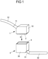
- Fig. 1 shows a schematic view of two connector parts 1, 3 that can be plugged together along a connection direction E.
- Each connector part 1, 3 has a connector housing 10, 30, in which a contact insert 2, 4 with contact elements arranged thereon is received.
- a cable 12, 32 is connected to the connector housing 10, 30 via a cable outlet 11, 31 and is electrically connected within the connector housing 10, 30 to the contact elements of the respectively assigned contact insert 2, 4.
- the present invention can be used not only for connector parts with manually handled connector housings, but can also be used, for example, for connectors provided on electrical systems, for example a control cabinet, in which a contact insert is to be fixed, for example, to a device wall, for example a control cabinet wall.
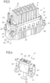
- Each contact insert 2, 4 has a frame part 20, 40 in the form of a rectangular frame, which forms a frame opening 201, 401 into which—in the illustrated embodiment—a contact module 21, 41 is inserted.
- a plug-in section 200, 400 is formed on the frame part 20, 40, wherein the plug-in section 200 of the first contact insert 2 forms a socket into which the plug-in section 400 of the frame part 40 of the other contact insert 4 can be inserted.
- Each contact module 21, 41 has a plurality of plug-in openings 210, 410 into which electrical lines 24 (see Fig. 3 ) for electrical contact with contact elements 211, 411 in the form of contact pins or contact sockets.
- electrical lines 24 see Fig. 3
- the contact elements 211 of one, first contact insert 2 engage with the associated contact elements 411 of the other, second contact insert 4, so that electrical contact is established between the contact inserts 2, 4.
- one or more contact modules can be inserted into the frame opening 201, 401 of each frame part 20, 40, so that individual contact arrangements can be created on the contact inserts 2, 4 to form a customized mating face.
- one contact module 21, 41 is precisely inserted into the frame part 20, 40 and connected to the frame part 20, 40 in a snap-in manner.
- Grounding elements 22, 42 are arranged on both sides of the frame part 20, 40, which, on the one hand, enable mechanical fixing of the contact insert 2, 4 to the associated connector housing 10, 30 via fastening elements 220, 420 and, on the other hand, provide protective contact between the contact inserts 2, 4.
- Each grounding element 22, 42 is supported on the frame part 20, 40 assigned to it via locking sections 221, 421, whereby in this way (if the frame part 20, 40 is made of an electrically conductive material, in particular a metal material), the frame part 20, 40 can also be included in the grounding.
- Contacting lugs 222, 422 extend on the respective associated plug-in section 200, 400 (see Fig. 5B in conjunction with Fig. 2 ) of the earthing elements 22, 42, which run onto each other when the contact inserts 2, 4 are plugged in and thus create an electrical contact between the earthing elements 22, 42 of the two contact inserts 2, 4.
- contacting devices 23', 43' in the form of screw connections for connecting protective lines are provided on the earthing elements 22, 42.
- a contacting device 23 is arranged on a grounding element 22, which contacting device comprises a housing 230 with two plug-in openings 231 for inserting protective lines 25 (see Fig. 6 ) and enables connection of the protective lines 25 by plug-in contact.
- the contacting device 23 has, as can be seen from the sectional view according to Fig. 6 As can be seen, two spring elements 26 are enclosed and held in the housing 230, each of which is assigned to one of the plug-in openings 231. Each spring element 26 has a clamping leg 260, which extends into the area of the plug-in opening 231 assigned to the spring element 26 and serves to lock and contact a protective line 25 inserted into the plug-in opening 231. A holding leg 261 is bent over to form the clamping leg 260 and is enclosed between housing sections 233 of the housing 230, so that the spring element 26 is fixed in the housing 230 via the holding leg 261.
- the clamping leg 260 is movable within the housing 230, undergoing elastic deformation relative to the retaining leg 261.
- a (stripped) wire end 250 of the protective cable 25 presses against the clamping leg 260 and pushes it aside, allowing the wire end 250 to slide past the clamping leg 260 and be elastically pressed against a contacting portion 223 of the grounding element 22 via the end of the clamping leg 260.
- the clamping leg 260 (acting like a barb) locks the protective cable 25 in the plug-in opening 231 when the protective cable 25 is (fully) inserted into the plug-in opening 231 with the wire end 250.
- the protective line 25 is thus held mechanically on the contacting device 23 via the spring element 26 on the one hand and is in planar contact with the contacting section 223 of the earthing element 22 on the other hand due to elastic pressure of the clamping leg 260.
- each plug-in opening 231 is assigned a release element 27, which can be displaced in a release opening 232 of the housing 230 such that, by applying pressure to the release element 27 (e.g., using a tool), the release element 27 slides with a body 270 in the release opening 232 and acts on the clamping leg 260 with an arm 271 protruding from the body 270, so that the latter is pressed out of contact with the wire end 250 of the protective cable 25.
- the protective cable 25 can thus be pulled out of the associated plug-in opening 231.
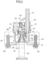
- Fig. 5A and 5B show a view of the contact insert 2 in the connected state with the contact insert 4 within the connector housing 30 associated with the contact insert 4 (the contact insert 2 is shown without the connector housing 10).
- both contact inserts 2, 4 each have a contacting device 23, 43 on a respective grounding element 22, 42, so that the connection of protective lines 25 in a plug-in manner with a reliable mechanical connection and electrical contact is possible for both contact inserts 2, 4.
- the contacting device 43 on the contact insert 4 is constructed identically to that described above for the contacting device 23 of the contact insert 2.
- the contact lugs 222, 422 of the grounding elements 22, 42 are in contact with one another.
- the contact lugs 222, 422 converge on one another and thus provide electrical contact for the common grounding of the contact inserts 2, 4.
- the earthing element 22, 42 is positively connected to the associated frame part 20, 40 of the contact insert 2, 4, as will be explained below with reference to Fig. 7 to 11 will be explained using an earthing element 22 of the contact insert 2 having a contacting device 23.
- the grounding element 22 has support sections 224 which extend transversely to the plugging direction S and carry the fastening elements 220 for fastening the contact insert 2 in the housing 10 of an associated connector part 1.
- the support sections 224 rest on an end section 205 of the plug-in section 200 of the frame part 20, as can be seen, for example, from Fig. 8 can be seen, and are supported above it in the plugging direction S on the frame part 20.
- the earthing element 22 (with the contacting device 23 arranged thereon) is attached in the plug-in direction S by pushing engagement sections 225 of the earthing element 22, which are bent over to form a wall section 226, in the plug-in direction S into engagement with associated engagement openings 203 on an end face 202 of the frame part 20 in order to thereby establish a positive connection (transverse to the plug-in direction S) between the earthing element 22 and the frame part 20.
- the locking sections 221 which protrude from the support sections 224 counter to the plug-in direction S, snap into engagement with undercuts 204 on the end face 202 of the frame part 20, so that the earthing element 22 is fixed in a locking manner counter to the plug-in direction S on the end face 202 of the frame part 20.
- the earthing element 22 is thus connected to the frame part 20 in a locking manner and is thereby fixed to the frame part 20.
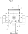
- the contacting device 23 is connected to the grounding element 22 via its housing 230 in a latching and thus form-fitting manner.
- the housing 230 has form-fitting sections 234 on both sides in the form of resilient latching tongues, which engage with the contacting sections 223 of the grounding element 22 when the housing 230 is placed in the plug-in direction S on the grounding element 22, as can be seen from a synopsis of Fig. 7 and Fig. 11 can be seen.
- the form-fitting sections 234 engage in latching openings 227 of the contacting sections 223 and thereby fix the housing 230 (with the spring elements 26 enclosed therein) to the grounding element 22.
- the contacting device 23 can thus be attached to the grounding element 22 in a simple manner by plugging the housing 230 into the grounding element 22 in the plugging direction S.
- the earthing element 22 can also be attached to the frame part 20 in a simple manner - with or without the contacting device 23 arranged thereon - so that the contact insert 2 can be easily installed.
- a grounding element 22 with a contacting device 23 of the type described can be used in particular on existing frame parts 20 without the need to significantly adapt the design of the frame part 20.
- Existing frame parts 20 can thus be equipped with grounding elements 22 and contacting devices 23 arranged thereon and, if necessary, also retrofitted.
- a contacting device for contacting an associated grounding element may have one or more plug-in openings for connecting one or more protective conductors.
- such a contacting device may have only one plug-in opening.
- exactly one contact module is attached to the associated frame part of a contact insert.
Landscapes
- Details Of Connecting Devices For Male And Female Coupling (AREA)
- Connector Housings Or Holding Contact Members (AREA)
Description
Die Erfindung betrifft einen Kontakteinsatz für ein Steckverbinderteil nach dem Oberbegriff des Anspruchs 1.The invention relates to a contact insert for a connector part according to the preamble of
Ein derartiger Kontakteinsatz umfasst ein Rahmenteil, das einen Steckabschnitt zum steckenden Verbinden mit einem weiteren Steckverbinderteil aufweist, zumindest ein an dem Steckabschnitt angeordnetes, elektrisches Kontaktelement und ein an dem Rahmenteil angeordnetes Erdungselement, an das eine Schutzleitung anschließbar ist.Such a contact insert comprises a frame part which has a plug-in section for plugging into another plug-in connector part, at least one electrical contact element arranged on the plug-in section and an earthing element arranged on the frame part to which a protective line can be connected.
Ein solcher Kontakteinsatz kann beispielsweise in ein Steckergehäuse eines Steckverbinderteils eingesetzt werden und ermöglicht auf diese Weise, Steckergehäuse mit ganz unterschiedlichen Kontakteinsätzen auszustatten und somit individuelle, einer bestimmten Verwendung angepasste Steckgesichter an dem Steckverbinderteil zur Verfügung zu stellen. An dem Steckabschnitt des Rahmenteils sind hierbei ein oder mehrere elektrische Kontaktelemente angeordnet, die bei Verbinden des Steckverbinderteils mit einem zugeordneten, weiteren Steckverbinderteil mit Kontaktelementen des weiteren Steckverbinderteils elektrisch kontaktierend in Eingriff gelangen, sodass eine elektrische Verbindung zwischen den Steckverbinderteilen hergestellt wird.Such a contact insert can, for example, be inserted into a connector housing of a connector part, thus enabling the connector housing to be equipped with very different contact inserts and thus providing individual mating faces on the connector part adapted to a specific application. One or more electrical contact elements are arranged on the mating section of the frame part. When the connector part is connected to an associated, further connector part, these electrically engage contact elements of the further connector part, thereby establishing an electrical connection between the connector parts.
Über das Erdungselement kann hierbei generell bei steckendem Verbinden der Steckverbinderteile eine Erdung zwischen den Steckverbinderteilen erfolgen, sodass die Steckverbinderteile in gestecktem Zustand auf gleichem Erdungspotenzial liegen. Über das Erdungselement kann hierbei beispielsweise auch das Rahmenteil, wenn dieses aus einem elektrisch leitfähigen (Metall-) Material hergestellt ist, geerdet werden.The grounding element can generally be used to ground the connector parts when plugged in, so that the connector parts are at the same ground potential when plugged in. The grounding element can also be used to ground the frame part, for example, if it is made of an electrically conductive (metal) material.
Bei einem aus der
Aus der
Aus der
Bei einem aus der
Herkömmlich ist vornehmlich vorgesehen worden, einen Anschluss zum Anschließen einer Schutzleitung als Schraubanschluss auszubilden. Dies ermöglicht eine zuverlässige, mechanisch feste Verbindung der Schutzleitung mit dem Kontakteinsatz, kann aber unter Umständen Beschränkungen in der Handhabbarkeit unterliegen. So kann ein Schraubanschluss unter Umständen, wenn der Kontakteinsatz in ein zugeordnetes Gehäuse eines Steckverbinderteils eingesetzt ist, nicht mehr einfach zugänglich sein, was erforderlich machen kann, eine Schutzleitung vor Einsetzen des Kontakteinsatzes in das Gehäuse zu befestigen. Zudem erfordert das Anbringen mehrerer Schutzleitungen das Anstecken der Schutzleitungen an den (einen) Schraubanschluss und das gleichzeitige Fixieren der Schutzleitungen durch Festziehen einer Schraube.
Aufgabe der vorliegenden Erfindung ist es, einen Kontakteinsatz für ein Steckverbinderteil zur Verfügung zu stellen, der einen einfachen Anschluss einer Schutzleitung ermöglicht.
Diese Aufgabe wird durch einen Gegenstand mit den Merkmalen des Anspruchs 1 gelöst. Demnach weist der Kontakteinsatz eine an dem Erdungselement angeordnete
Kontaktierungseinrichtung auf, die ein Gehäuse mit einer Stecköffnung zum Einstecken der Schutzleitung und ein an dem Gehäuse angeordnetes Federelement zum Arretieren der Schutzleitung in der Stecköffnung und zum Kontaktieren der Schutzleitung mit dem Erdungselement aufweist.Traditionally, the primary design for connecting a protective wire has been a screw connection. This enables a reliable, mechanically secure connection between the protective wire and the contact insert, but can be subject to handling limitations under certain circumstances. For example, a screw connection may no longer be easily accessible once the contact insert is inserted into an associated housing of a connector part, which may make it necessary to secure a protective wire before inserting the contact insert into the housing. Furthermore, attaching multiple protective wires requires plugging the protective wires into the (one) screw connection and simultaneously securing the protective wires by tightening a screw.
The object of the present invention is to provide a contact insert for a connector part which enables a simple connection of a protective line.
This object is achieved by an article having the features of
Contacting device which has a housing with a plug-in opening for inserting the protective line and a spring element arranged on the housing for locking the protective line in the plug-in opening and for contacting the protective line with the earthing element.
Ein solches Erdungselement kann lösbar mit einer daran angeordneten Kontaktierungseinrichtung an einem Rahmenteil eines Kontakteinsatzes angeordnet werden. Dies kann gegebenenfalls eine Bestückung eines Kontakteinsatzes mit einem Erdungselement und einer daran angeordneten Kontaktierungseinrichtung ermöglichen, ohne dass hierzu die Bauform des Rahmenteils angepasst werden muss. Ein solches Erdungselement mit einer daran angeordneten Kontaktierungseinrichtung kann somit gegebenenfalls an einem bereits bestehenden Rahmenteil zum Einsatz kommen und gegebenenfalls auch nachgerüstet werden.Such a grounding element can be detachably mounted on a frame part of a contact insert with a contacting device arranged thereon. This can, if necessary, enable the contact insert to be equipped with a grounding element and a contacting device arranged thereon without having to adapt the design of the frame part. Such a grounding element with a contacting device arranged thereon can thus be used on an existing frame part and, if necessary, even retrofitted.
Das Anschließen der Schutzleitung an das Erdungselement an dem Rahmenteil erfolgt über einen Federkraftanschluss. Zum Verbinden der Schutzleitung mit dem Erdungselement kann die Schutzleitung in einfacher, bequemer Weise mit einem (abisolierten) Aderende in die Stecköffnung des Gehäuses der Kontaktierungseinrichtung eingesteckt werden und gelangt dadurch in den Bereich des Federelements, die die Schutzleitung in dem Gehäuse arretiert und ein Kontaktieren der Schutzleitung mit dem Erdungselement bewirkt. Zum Anschließen ist somit (lediglich) ein Einstecken der Schutzleitung erforderlich. Das Arretieren und Kontaktieren der Schutzleitung mit dem Erdungselement kann hierbei vorteilhafterweise selbsttätig erfolgen, ohne dass weitere Bedienungsschritte zum Festlegen der Schutzleitung an dem Erdungselement erforderlich sind.The protective cable is connected to the grounding element on the frame part via a spring-loaded connection. To connect the protective cable to the grounding element, the protective cable can be easily and conveniently inserted with a (stripped) wire end into the plug-in opening of the contacting device housing. It is inserted and thus reaches the area of the spring element, which locks the protective cable in the housing and ensures contact between the protective cable and the grounding element. Therefore, connection requires (only) plugging in the protective cable. The locking and contact of the protective cable with the grounding element can advantageously occur automatically, without the need for further operating steps to secure the protective cable to the grounding element.
Das Federelement weist, in einer Ausgestaltung, einen Klemmschenkel auf, der bei in die Stecköffnung eingesteckter Schutzleitung mit der Schutzleitung in Anlage ist. Über den Klemmschenkel erfolgt die Arretierung der Schutzleitung in dem Gehäuse der Kontaktierungseinrichtung, wobei zur Kontaktierung der Schutzleitung mit dem Erdungselement der Klemmschenkel beispielsweise ausgebildet ist, die Schutzleitung gegen einen Kontaktierungsabschnitt des Erdungselements zu drücken und somit die Schutzleitung in elektrischen Kontakt mit dem Erdungselement zu bringen.In one embodiment, the spring element has a clamping leg that engages the protective cable when inserted into the plug-in opening. The protective cable is locked in the housing of the contacting device via the clamping leg. For contacting the protective cable with the grounding element, the clamping leg is configured, for example, to press the protective cable against a contact section of the grounding element, thus bringing the protective cable into electrical contact with the grounding element.
Bei Einstecken der Schutzleitung in die Stecköffnung des Gehäuses wirkt die Schutzleitung auf den Klemmschenkel des Federelements ein und lenkt diesen vorzugsweise federelastisch derart aus, dass die Arretierung der Schutzleitung in dem Gehäuse unter Kontaktierung mit dem Erdungselement bewirkt wird. Der Klemmschenkel ist hierzu bewegbar in dem Gehäuse angeordnet.When the protective cable is inserted into the plug-in opening of the housing, the protective cable acts on the clamping leg of the spring element and deflects it, preferably elastically, in such a way that the protective cable is locked in the housing and contacted with the grounding element. For this purpose, the clamping leg is movably arranged within the housing.
Zusätzlich zu dem Klemmschenkel weist das Federelement, in einer Ausgestaltung, einen Halteschenkel auf, über den das Federelement an dem Gehäuse gehalten ist. Der Halteschenkel kann beispielsweise zu dem Klemmschenkel umgebogen und zwischen Gehäuseabschnitten des Gehäuses derart festgelegt sein, dass über den Halteschenkel das Federelement an dem Gehäuse befestigt ist. Bei Einstecken der Schutzleitung in die Stecköffnung des Gehäuses wirkt die Schutzleitung auf den Klemmschenkel ein und bewegt den Klemmschenkel zu dem Halteschenkel unter elastischer Verformung des Federelements, sodass die Schutzleitung unter Vorspannung in dem Gehäuse der Kontaktierungseinrichtung gehalten wird.In addition to the clamping leg, the spring element, in one embodiment, has a retaining leg, via which the spring element is held to the housing. The retaining leg can, for example, be bent over to form the clamping leg and secured between housing sections of the housing in such a way that the spring element is attached to the housing via the retaining leg. When the protective cable is inserted into the plug-in opening of the housing, the protective cable acts on the clamping leg and moves the clamping leg toward the retaining leg, elastically deforming the spring element, so that the protective cable is held under prestress in the housing of the contacting device.
Die Verbindung der Schutzleitung mit der Kontaktierungseinrichtung ist vorzugsweise lösbar. Hierzu kann die Kontaktierungseinrichtung beispielsweise ein Entsperrelement aufweisen, das zum Lösen der Schutzleitung betätigt werden kann und beispielsweise einen Arm aufweist, mit dem das Entsperrelement bei Betätigung auf das Federelement einwirkt. Das Entsperrelement kann beispielsweise durch ein Werkzeug, zum Beispiel einen Schraubendreher, betätigt werden und zur Betätigung in das Gehäuse der Kontaktierungseinrichtung hinein zu drücken sein. Hierdurch wirkt das Entsperrelement mit seinem Arm auf den Klemmschenkel des Federelements ein und drückt diesen außer Anlage mit der Schutzleitung, sodass die Arretierung der Schutzleitung in dem Gehäuse aufgehoben ist und die Schutzleitung somit aus der Stecköffnung herausgezogen werden kann.The connection between the protective cable and the contacting device is preferably detachable. For this purpose, the contacting device can, for example, have a release element that can be actuated to release the protective cable and, for example, has an arm with which the release element acts on the spring element when actuated. The release element can, for example, be actuated using a tool, such as a screwdriver, and can be pressed into the housing of the contacting device for actuation. As a result, the release element acts with its arm on the clamping leg of the spring element and presses it out of contact with the protective cable, so that the locking of the protective cable in the housing is released and the protective cable can thus be pulled out of the plug-in opening.
In einer Ausgestaltung kann das Gehäuse der Kontaktierungseinrichtung zwei (getrennte) Stecköffnungen zum Einstecken von zwei Schutzleitungen und zwei Federelemente zum Arretieren der Schutzleitungen in den Stecköffnungen aufweisen. Die Kontaktierungseinrichtung stellt somit zwei Steckplätze zum Anschließen zweier Schutzleitungen bereit, wobei grundsätzlich auch denkbar und möglich ist, noch mehr Steckplätze, z.B. drei oder vier Steckplätze, zum Anschließen von mehr als zwei Schutzleitungen vorzusehen. Auf diese Weise können mehrere Schutzleitungen in einfacher, bequemer Weise unter zuverlässiger elektrischer Kontaktierung mit dem Erdungselement und bei zuverlässigem mechanischen Halt an die Kontaktierungseinrichtung angeschlossen werden.In one embodiment, the housing of the contacting device can have two (separate) plug-in openings for inserting two protective conductors and two spring elements for locking the protective conductors in the plug-in openings. The contacting device thus provides two plug-in locations for connecting two protective conductors. It is also conceivable and possible, in principle, to provide even more plug-in locations, e.g., three or four plug-in locations, for connecting more than two protective conductors. In this way, multiple protective conductors can be connected to the contacting device in a simple and convenient manner, ensuring reliable electrical contact with the grounding element and reliable mechanical support.
Jedes Federelement kann hierbei wie vorangehend beschrieben ausgebildet sein und insbesondere einen Klemmschenkel zum Arretieren und Kontaktieren der Schutzleitung aufweisen.Each spring element can be designed as described above and in particular have a clamping leg for locking and contacting the protective line.
Das Erdungselement weist beispielsweise eine Kontaktierungsfahne zum erdenden Kontaktieren mit dem weiteren Steckverbinderteil auf. Die Kontaktierungsfahne kann beispielsweise entlang einer Verbindungsrichtung, entlang derer die Steckverbinderteile miteinander zu verbinden sind, an dem Rahmenteil erstreckt sein, sodass die Kontaktierungsfahne bei steckendem Verbinden des Steckverbinderteils mit dem weiteren Steckverbinderteil auf einen zugeordneten Kontaktabschnitt an dem weiteren Steckverbinderteil aufläuft und dadurch eine Verbindung zwischen den Steckverbinderteilen zur gemeinsamen Erdung herstellt.The grounding element has, for example, a contact lug for establishing grounding contact with the additional connector part. The contact lug can, for example, extend along a connection direction along which the connector parts are to be connected to one another on the frame part, so that when the connector part is plugged into the additional connector part, the contact lug runs onto an associated contact section on the additional connector part, thereby establishing a connection between the connector parts for common grounding.
Der Kontakteinsatz kann modular ausgebildet sein. Beispielsweise kann vorgesehen sein, dass an das Rahmenteil, das beispielsweise als rechteckiger Aufnahmerahmen ausgebildet sein kann, ein oder mehrere modulare Kontaktmodule angesetzt werden können, um das Rahmenteil modular mit Kontaktmodulen zu bestücken und somit einen individuellen Kontakteinsatz für ein Steckverbinderteil zu schaffen. Jedes Kontaktmodul kann hierbei ein oder mehrere Stecköffnungen zum Einstecken elektrischer Leitungen aufweisen und kann zudem ein oder mehrere Kontaktelemente zum Kontaktieren mit einem zugeordneten weiteren Steckverbinderteil aufweisen. An dem Rahmenteil können beispielsweise eine Mehrzahl von (entlang einer Querrichtung quer zur Verbindungsrichtung zueinander versetzten) Steckplätzen vorgesehen sein, in die eine Mehrzahl von Kontaktmodulen eingesteckt werden kann.The contact insert can be of modular design. For example, it can be provided that one or more modular contact modules can be attached to the frame part, which can be designed, for example, as a rectangular receiving frame, in order to modularly equip the frame part with contact modules and thus create an individual contact insert for a connector part. Each contact module can have one or more plug-in openings for inserting electrical cables and can also have one or more contact elements for making contact with an associated further connector part. For example, a plurality of plug-in locations (offset from one another along a transverse direction transverse to the connection direction) can be provided on the frame part, into which plug-in locations a plurality of contact modules can be inserted.
Ist der Kontakteinsatz modular mit modular an das Rahmenteil anzusetzenden Kontaktmodulen ausgebildet, sind die Kontaktelemente des Kontakteinsatzes vorzugsweise Bestandteil der Kontaktmodule. In diesem Fall kann der Steckabschnitt zum steckenden Verbinden mit dem weiteren Steckverbinderteil einstückig an dem Rahmenteil geformt oder auch durch die Kontaktmodule gebildet sein. Ist der Steckabschnitt durch die Kontaktmodule gebildet, bilden die Kontaktmodule somit das Steckgesicht des Steckverbinderteils, an dem der Kontakteinsatz zum Einsatz kommt, aus.If the contact insert is designed modularly with contact modules that are attached to the frame part, the contact elements of the contact insert are preferably components of the contact modules. In this case, the plug-in section for plugging into the other connector part can be formed integrally on the frame part or can also be formed by the contact modules. If the plug-in section is formed by the contact modules The contact modules thus form the mating face of the connector part on which the contact insert is used.
Ein an das Rahmenteil anzusetzendes Kontaktmodul kann so ausgestaltet sein, dass eine Leitung in eine Steckrichtung in eine Stecköffnung des Kontaktmoduls einzustecken ist. Vorzugsweise ist hierbei auch die Schutzleitung entlang der Steckrichtung in die Stecköffnung der Kontaktierungseinrichtung einzustecken, sodass das Anschließen der Schutzleitung an die Kontaktierungseinrichtung des Erdungselements in die gleiche Richtung wie das Anschließen von anderen elektrischen Leitungen an die Stecköffnungen des Kontaktmoduls erfolgt. Auch das Anschließen der elektrischen Leitungen an das Kontaktmodul kann hierbei über Federkraftanschlüsse erfolgen, sodass Schutzleitungen genauso wie andere Leitungen (beispielsweise für eine Datenübertragung oder zum Bereitstellen einer elektrischen Versorgung) in einfacher, gegebenenfalls auch automatisierbarer Weise an den Kontakteinsatz angesteckt werden können.A contact module to be attached to the frame part can be designed such that a cable can be inserted into a plug-in opening of the contact module in one plug-in direction. Preferably, the protective cable can also be inserted into the plug-in opening of the contacting device along the plug-in direction, so that the protective cable is connected to the contacting device of the earthing element in the same direction as other electrical cables are connected to the plug-in openings of the contact module. The electrical cables can also be connected to the contact module via spring-loaded connections, so that protective cables, like other cables (e.g., for data transmission or to provide an electrical supply), can be plugged into the contact insert in a simple, and possibly even automated, manner.
In einer Ausgestaltung weist das Rahmenteil eine Rahmenöffnung auf, in die das Kontaktmodul eingesetzt ist. Das (in seiner Grundform rechteckige) Rahmenteil umschließt die Rahmenöffnung und schafft somit einen Aufnahmeraum mit Steckplätzen, in die ein oder mehrere Kontaktmodule eingesetzt werden können, um in eingesetzter Stellung mit dem Rahmenteil zu verrasten und somit ein (modular konfigurierbares) Steckgesicht an dem Rahmenteil zu schaffen. Das eine oder die mehreren Kontaktmodule können in die Steckrichtung in die Rahmenöffnung einzusetzen sein und sind in eingesetzter Stellung mit dem Rahmenteil verrastet.In one embodiment, the frame part has a frame opening into which the contact module is inserted. The frame part (which is rectangular in its basic shape) encloses the frame opening and thus creates a receiving space with slots into which one or more contact modules can be inserted. In the inserted position, they lock into the frame part and thus create a (modularly configurable) mating face on the frame part. The one or more contact modules can be inserted into the frame opening in the insertion direction and are locked into the frame part in the inserted position.
Das Erdungselement ist hierbei außerhalb der Rahmenöffnung an dem Rahmenteil, zum Beispiel an einer schmalen Stirnseite des (rechteckigen) Rahmenteils, angeordnet. Während ein oder mehrere Kontaktmodule somit in die vom Rahmenteil umschlossene Rahmenöffnung eingesetzt sind, ist das Erdungselement mit der daran angeordneten Kontaktierungseinrichtung außerhalb der Rahmenöffnung an dem Rahmenteil, insbesondere im Bereich der Stirnseite des Rahmenteils, befestigt. Denkbar ist, dass das Rahmenteil ein (einziges) Erdungselement mit einer daran angeordneten Kontaktierungseinrichtung aufweist. Denkbar und möglich ist aber auch, dass beidseitig des Rahmenteils an einander gegenüberliegenden Stirnseiten des Rahmenteils jeweils ein Erdungselement angeordnet ist, wobei in diesem Fall beide Erdungselemente oder auch nur eines der Erdungselemente eine Kontaktierungseinrichtung aufweisen können.The grounding element is arranged outside the frame opening on the frame part, for example on a narrow end face of the (rectangular) frame part. While one or more contact modules are thus inserted into the frame opening enclosed by the frame part, the grounding element with the contacting device arranged thereon is fastened outside the frame opening on the frame part, in particular in the region of the end face of the frame part. It is conceivable that the frame part has a (single) grounding element with a contacting device arranged thereon. However, it is also conceivable and possible that a grounding element is arranged on each side of the frame part on opposite end faces of the frame part, in which case both grounding elements or just one of the grounding elements can have a contacting device.
In einer Ausgestaltung ist das Erdungselement formschlüssig mit dem Rahmenteil verbunden. Das Erdungselement ist somit derart an das Rahmenteil angesetzt, dass eine formschlüssige Verbindung zwischen dem Rahmenteil und dem Erdungselement besteht und somit das Erdungselement an dem Rahmenteil gehalten ist.In one embodiment, the grounding element is positively connected to the frame part. The grounding element is thus attached to the frame part in such a way that a positive connection exists between the frame part and the grounding element, thus holding the grounding element to the frame part.
Eine solche formschlüssige Verbindung kann zum Beispiel über einen in eine Eingriffsöffnung des Rahmenteils einzuschiebenden Eingriffsabschnitt des Erdungselements und (zusätzlich oder alternativ) über einen eine Rastverbindung mit dem Rahmenteil herstellenden Rastabschnitt hergestellt werden. Der Eingriffsabschnitt kann beispielsweise entlang der Steckrichtung in die zugeordnete Eingriffsöffnung des Rahmenteils einzuschieben sein und stellt einen Formschluss zwischen dem Erdungselement und dem Rahmenteil quer zur Steckrichtung her. Der Rastabschnitt kann demgegenüber zum Beispiel bei einem Einschieben des Eingriffsabschnitts in die zugeordnete Eingriffsöffnung mit einem Hinterschnitt des Rahmenteils rastend in Eingriff gelangen, um auf diese Weise das Erdungselement entlang der Steckrichtung formschlüssig zu dem Rahmenteil festzulegen. Über den Eingriffsabschnitt und den Rastabschnitt ist das Erdungselement in an das Rahmenteil angesetzter Stellung somit zu dem Rahmenteil festgelegt.Such a positive connection can be established, for example, via an engagement section of the grounding element that can be inserted into an engagement opening in the frame part and (additionally or alternatively) via a locking section that creates a snap-in connection with the frame part. The engagement section can, for example, be inserted along the plug-in direction into the associated engagement opening of the frame part and creates a positive connection between the grounding element and the frame part transversely to the plug-in direction. In contrast, the locking section can, for example, when the engagement section is inserted into the associated engagement opening, engage in a snap-in engagement with an undercut of the frame part in order to secure the grounding element to the frame part in a positive-locking manner along the plug-in direction. The engagement section and the locking section thus secure the grounding element to the frame part when attached to the frame part.
Es ergibt sich eine Anordnung, bei der das Erdungselement in einfacher Weise zur Montage des Kontakteinsatzes an das Rahmenteil angesetzt werden kann und in angesetzter Stellung fest und belastbar an dem Rahmenteil gehalten ist.This results in an arrangement in which the earthing element can be easily attached to the frame part for mounting the contact insert and is held firmly and resiliently to the frame part in the attached position.
In einer Ausgestaltung ist das Gehäuse der Kontaktierungseinrichtung formschlüssig mit dem Erdungselement verbunden. Das Gehäuse kann beispielsweise aus einem elektrisch isolierenden Kunststoffmaterial hergestellt sein und fasst das Federelement zur Verwirklichung des Federkraftanschlusses ein. Das Gehäuse kann beispielsweise einen Formschlussabschnitt (zum Beispiel in Form einer federnden Rastzunge) aufweisen, über den das Gehäuse in angesetzter Stellung mit dem Erdungselement verrastet ist. Auch die Verbindung zwischen dem Gehäuse der Kontaktierungseinrichtung und dem Erdungselement erfolgt somit in formschlüssiger, rastender Weise, was ein einfaches Ansetzen des Gehäuses an das Erdungselement ermöglicht, bei zudem festem Halt in angesetzter Stellung.In one embodiment, the housing of the contacting device is positively connected to the grounding element. The housing can, for example, be made of an electrically insulating plastic material and encloses the spring element to create the spring-loaded connection. The housing can, for example, have a positive-locking section (for example, in the form of a resilient latching tongue), via which the housing is latched to the grounding element in the attached position. The connection between the housing of the contacting device and the grounding element is thus also positively latched, which enables easy attachment of the housing to the grounding element while also ensuring a firm hold in the attached position.
Der Kontakteinsatz kann beispielsweise an einem Steckverbinderteil verwendet werden, wobei ein solches Steckverbinderteil ein Steckergehäuse aufweisen kann, in dem der Kontakteinsatz aufgenommen wird. Solch ein Steckergehäuse kann an ein elektrisches Kabel mit einer Vielzahl von Leitungsadern angeschlossen sein. Denkbar und möglich ist aber auch, einen solchen Kontakteinsatz beispielsweise an einem Anbaugehäuse an einem Schaltschrank oder einer anderen elektrischen Anlagen zu verwenden.The contact insert can be used, for example, on a connector part, whereby such a connector part can have a connector housing in which the contact insert is accommodated. Such a connector housing can be connected to an electrical cable with a plurality of conductors. However, it is also conceivable and possible to use such a contact insert, for example, on a mounting housing on a control cabinet or other electrical system.
Der der Erfindung zugrunde liegende Gedanke soll nachfolgend anhand der in den Figuren dargestellten Ausführungsbeispiele näher erläutert werden. Es zeigen:
- Fig. 1
- eine schematische Ansicht zweier Steckverbinderteile, die steckend entlang einer Verbindungsrichtung miteinander verbunden werden können;
- Fig. 2
- eine Ansicht zweier Kontakteinsätze der Steckverbinderteile;
- Fig. 3
- eine Ansicht eines Ausführungsbeispiels eines Kontakteinsatzes, der ein Rahmenteil, daran angeordnete Erdungselemente und eine Kontaktierungseinrichtung zum Anschließen einer Schutzleitung an eines der Erdungselemente aufweist;
- Fig. 4
- eine gesonderte Ansicht eines Erdungselements mit einer Kontaktierungseinrichtung;
- Fig. 5A
- eine Ansicht eines Kontakteinsatzes eines Steckverbinderteils in verbundenem Zustand mit einem Kontakteinsatz eines weiteren Steckverbinderteils;
- Fig. 5B
- eine Schnittansicht entlang der Linie A-A gemäß
Fig. 5A ; - Fig. 6
- eine Schnittansicht entlang der Linie B-B gemäß
Fig. 4 ; - Fig. 7
- eine Ansicht des Erdungselements mit der daran angeordneten Kontaktierungseinrichtung;
- Fig. 8
- eine gesonderte Ansicht des Erdungselements an dem Rahmenteil des Kontakteinsatzes;
- Fig. 9
- eine Seitenansicht der Anordnung gemäß
Fig. 8 ; - Fig. 10
- eine Draufsicht auf die Anordnung gemäß
Fig. 8 ; und - Fig. 11
- eine rückseitige Ansicht des Erdungselements (betrachtet von Seiten des Rahmenteils) mit der daran angeordneten Kontaktierungseinrichtung.
- Fig. 1
- a schematic view of two connector parts that can be connected to each other along a connection direction;
- Fig. 2
- a view of two contact inserts of the connector parts;
- Fig. 3
- a view of an embodiment of a contact insert comprising a frame part, grounding elements arranged thereon and a contacting device for connecting a protective line to one of the grounding elements;
- Fig. 4
- a separate view of an earthing element with a contacting device;
- Fig. 5A
- a view of a contact insert of a connector part in a connected state with a contact insert of another connector part;
- Fig. 5B
- a sectional view along the line AA according to
Fig. 5A ; - Fig. 6
- a sectional view along the line BB according to
Fig. 4 ; - Fig. 7
- a view of the earthing element with the contacting device arranged thereon;
- Fig. 8
- a separate view of the earthing element on the frame part of the contact insert;
- Fig. 9
- a side view of the arrangement according to
Fig. 8 ; - Fig. 10
- a plan view of the arrangement according to
Fig. 8 ; and - Fig. 11
- a rear view of the earthing element (viewed from the frame part side) with the contacting device arranged thereon.
Angemerkt sei bereits an dieser Stelle, dass die vorliegende Erfindung nicht nur bei Steckverbinderteilen mit händisch zu handhabenden Steckergehäusen einsetzbar ist, sondern beispielsweise auch bei an elektrischen Anlagen, beispielsweise einem Schaltschrank, vorgesehenen Steckverbindern verwendet werden kann, bei denen ein Kontakteinsatz beispielsweise an einer Gerätewand, beispielsweise einer Schaltschrankwand, festzulegen ist.It should be noted at this point that the present invention can be used not only for connector parts with manually handled connector housings, but can also be used, for example, for connectors provided on electrical systems, for example a control cabinet, in which a contact insert is to be fixed, for example, to a device wall, for example a control cabinet wall.
Ein Ausführungsbeispiel zweier entlang der Verbindungsrichtung E steckend miteinander zu verbindender Kontakteinsätze 2, 4 zeigt
Jedes Kontaktmodul 21, 41 weist eine Mehrzahl von Stecköffnungen 210, 410 auf, in die elektrische Leitungen 24 (siehe
In die Rahmenöffnung 201, 401 eines jeden Rahmenteils 20, 40 können grundsätzlich ein oder mehrere Kontaktmodule eingesetzt werden, sodass an den Kontakteinsätzen 2, 4 individuelle Kontaktanordnungen zur Ausbildung eines individuellen Steckgesichtes geschaffen werden können. Bei dem dargestellten Ausführungsbeispiel ist (genau) ein Kontaktmodul 21, 41 passgenau in das Rahmenteil 20, 40 eingesetzt und rastend mit dem Rahmenteil 20, 40 verbunden. Möglich ist aber auch, mehrere (kleinere) Kontaktmodule nebeneinander in dem Rahmenteil 20, 40 anzuordnen.In principle, one or more contact modules can be inserted into the
Beidseits des Rahmenteils 20, 40 sind Erdungselemente 22, 42 angeordnet, die zum einen über Befestigungselemente 220, 420 eine mechanische Festlegung des Kontakteinsatzes 2, 4 an dem zugeordneten Steckergehäuse 10, 30 ermöglichen und zum anderen eine Schutzkontaktierung zwischen den Kontakteinsätzen 2, 4 bereitstellen. Jedes Erdungselement 22, 42 ist über Rastabschnitte 221, 421 an dem ihm zugeordneten Rahmenteil 20, 40 abgestützt, wobei auf diese Weise (wenn das Rahmenteil 20, 40 aus einem elektrisch leitfähigen Material, insbesondere einem Metallmaterial, gefertigt ist) auch das Rahmenteil 20, 40 in die Erdung mit einbezogen sein kann.Grounding
An dem jeweils zugeordneten Steckabschnitt 200, 400 erstrecken sich Kontaktierungsfahnen 222, 422 (siehe
Bei dem in
Demgegenüber ist bei dem in
Die Kontaktierungseinrichtung 23 weist, wie aus der Schnittansicht gemäß
Der Klemmschenkel 260 ist in dem Gehäuse 230 bewegbar, unter elastischer Verformung zu dem Halteschenkel 261. Bei Einstecken einer Schutzleitung 25 drückt ein (abisoliertes) Aderende 250 der Schutzleitung 25 auf den Klemmschenkel 260 und drückt diesen beiseite, sodass das Aderende 250 an dem Klemmschenkel 260 vorbei gleiten kann und über das Ende des Klemmschenkels 260 elastisch gegen einen Kontaktierungsabschnitt 223 des Erdungselements 22 gedrückt wird. Durch den (nach Art eines Widerhakens wirkenden) Klemmschenkel 260 ist die Schutzleitung 25 in der Stecköffnung 231 arretiert, wenn die Schutzleitung 25 mit dem Aderende 250 (vollständig) in die Stecköffnung 231 eingesteckt ist. Die Schutzleitung 25 ist über das Federelement 26 somit zum einen mechanisch an der Kontaktierungseinrichtung 23 gehalten und ist zum anderen durch elastischen Druck des Klemmschenkels 260 in flächiger Anlage mit dem Kontaktierungsabschnitt 223 des Erdungselements 22.The clamping
Die Verbindung der Schutzleitung 25 mit der Kontaktierungseinrichtung 23 ist lösbar. Hierzu ist jeder Stecköffnung 231 ein Entsperrelement 27 zugeordnet, das in einer Entsperröffnung 232 des Gehäuses 230 verschiebbar ist derart, dass durch Druck auf das Entsperrelement 27 (z.B. mittels eines Werkzeugs) das Entsperrelement 27 mit einem Körper 270 in der Entsperröffnung 232 gleitet und mit einem von dem Körper 270 vorstehenden Arm 271 auf den Klemmschenkel 260 einwirkt, sodass dieser außer Anlage mit dem Aderende 250 der Schutzleitung 25 gedrückt wird. Die Schutzleitung 25 kann somit aus der zugeordneten Stecköffnung 231 herausgezogen werden.The connection of the
Bei dem in
Über die Kontaktierungseinrichtung 23 ist ein Anschließen einer Schutzleitung 25 an das zugeordnete Erdungselement 22 in einfacher Weise durch Einstecken in eine der Stecköffnungen 231 möglich. Wie aus
Wie zudem aus
Das Erdungselement 22, 42 ist bei dem dargestellten Ausführungsbeispiel formschlüssig mit dem zugeordneten Rahmenteil 20, 40 des Kontakteinsatzes 2, 4 verbunden, wie dies nachfolgend anhand von
Das Erdungselement 22 weist Auflageabschnitt 224 auf, die sich quer zur Steckrichtung S erstrecken und die Befestigungselemente 220 zur Befestigung des Kontakteinsatzes 2 in dem Gehäuse 10 eines zugeordneten Steckverbinderteils 1 tragen. In einer mit dem Rahmenteil 20 verbundenen Stellung des Erdungselements 20 liegen die Auflageabschnitte 224 auf einem Endabschnitt 205 des Steckabschnitts 200 des Rahmenteils 20 auf, wie dies zum Beispiel aus
Das Ansetzen des Erdungselements 22 (mit der daran angeordneten Kontaktierungseinrichtung 23) erfolgt in die Steckrichtung S, indem zu einem Wandungsabschnitt 226 umgebogene Eingriffsabschnitte 225 des Erdungselements 22 in die Steckrichtung S in Eingriff mit zugeordneten Eingriffsöffnungen 203 an einer Stirnseite 202 des Rahmenteils 20 geschoben werden, um auf diese Weise einen Formschluss (quer zur Steckrichtung S) zwischen dem Erdungselement 22 und dem Rahmenteil 20 herzustellen.The earthing element 22 (with the contacting
Ist das Erdungselement 22 an das Rahmenteil 20 angesetzt und sind die Eingriffsabschnitte 225 in Eingriff mit den zugeordneten Eingriffsöffnungen 203 geschoben worden, bis die Auflageabschnitte 224 in Auflage mit dem Endabschnitt 205 des Steckabschnitts 200 des Rahmenteils 20 gelangen, schnappen die Rastabschnitte 221, die entgegen der Steckrichtung S von den Auflageabschnitten 224 vorstehen, in Eingriff mit Hinterschnitten 204 an der Stirnseite 202 des Rahmenteils 20, sodass das Erdungselement 22 entgegen der Steckrichtung S an der Stirnseite 202 des Rahmenteils 20 rastend festgelegt ist.If the earthing
In angesetzter Stellung ist das Erdungselement 22 somit rastend mit dem Rahmenteil 20 verbunden und dadurch an dem Rahmenteil 20 festgelegt.In the attached position, the earthing
Die Kontaktierungseinrichtung 23 ist über ihr Gehäuse 230 rastend und damit formschlüssig mit dem Erdungselement 22 verbunden. Das Gehäuse 230 weist hierzu beidseits Formschlussabschnitte 234 in Form von federnden Rastzungen auf, die bei Ansetzen des Gehäuses 230 in die Steckrichtung S an das Erdungselement 22 mit den Kontaktierungsabschnitten 223 des Erdungselements 22 in Eingriff gelangen, wie dies aus einer Zusammenschau von
Die Kontaktierungseinrichtung 23 kann somit in einfacher Weise an das Erdungselement 22 angesetzt werden, indem das Gehäuse 230 in die Steckrichtung S an das Erdungselement 22 angesteckt wird.The contacting
Zudem kann auch das Erdungselement 22 in einfacher Weise - mit oder ohne daran angeordneter Kontaktierungseinrichtung 23 - an das Rahmenteil 20 angesetzt werden, sodass sich eine einfache Montage des Kontakteinsatzes 2 ergibt.In addition, the earthing
Ein Erdungselement 22 mit einer daran angeordneten Kontaktierungseinrichtung 23 der beschriebenen Art kann insbesondere an bereits bestehenden Rahmenteilen 20 zum Einsatz kommen, ohne dass die Bauform des Rahmenteils 20 wesentlich angepasst werden muss. Bestehende Rahmenteile 20 können somit mit Erdungselementen 22 und daran angeordneten Kontaktierungseinrichtungen 23 bestückt und gegebenenfalls auch nachgerüstet werden.A
Der der Erfindung zugrunde liegende Gedanke ist nicht auf die vorangehend geschilderten Ausführungsbeispiele beschränkt, sondern lässt sich grundsätzlich auch in gänzlich anders gearteter Weise verwirklichen.The idea underlying the invention is not limited to the embodiments described above, but can in principle also be implemented in a completely different way.
An einer Kontaktierungseinrichtung zur Kontaktierung mit einem zugeordneten Erdungselement können ein oder mehrere Stecköffnungen zum Anschließen eines oder mehrerer Schutzleitungen vorgesehen sein. Z.B. kann eine solche Kontaktierungseinrichtung nur eine Stecköffnung aufweisen. Denkbar und möglich ist aber auch, an einer solchen Kontaktierungseinrichtung mehr als zwei Stecköffnungen zum Verbinden von mehr als zwei Schutzleitungen vorzusehen.A contacting device for contacting an associated grounding element may have one or more plug-in openings for connecting one or more protective conductors. For example, such a contacting device may have only one plug-in opening. However, it is also conceivable and possible to provide more than two plug-in openings on such a contacting device for connecting more than two protective conductors.
Bei dem dargestellten Ausführungsbeispiel ist genau ein Kontaktmodul an das zugeordnete Rahmenteil eines Kontakteinsatzes angesetzt. Denkbar und möglich ist aber auch, mehrere Kontaktmodule nebeneinander zu Bereitstellung unterschiedlicher Kontaktelemente zum Schaffen eines individuell angepassten Steckgesichtes in das Rahmenteil des Kontakteinsatzes einzusetzen.In the illustrated embodiment, exactly one contact module is attached to the associated frame part of a contact insert. However, it is also conceivable and possible to insert several contact modules side by side into the frame part of the contact insert to provide different contact elements and create a customized mating face.
- 11
- SteckverbinderteilConnector part
- 1010
- Steckergehäuseconnector housing
- 1111
- KabelabgangCable outlet
- 1212
- KabelCable
- 22
- KontakteinsatzContact insert
- 2020
- Rahmenteil (Modulrahmen)Frame part (modular frame)
- 200200
- SteckabschnittPlug-in section
- 201201
- RahmenöffnungFrame opening
- 202202
- Stirnseitefront side
- 203203
- EingriffsöffnungAccess opening
- 204204
- Hinterschnittundercut
- 205205
- Endabschnittfinal section
- 2121
- KontaktmodulContact module
- 210210
- StecköffnungenPlug-in openings
- 211211
- KontaktelementeContact elements
- 2222
- Erdungselement (PE-Blech)Earthing element (PE sheet)
- 220220
- BefestigungselementFastening element
- 221221
- RastabschnittRest area
- 222222
- KontaktierungsfahneContacting flag
- 223223
- KontaktierungsabschnittContacting section
- 224224
- Auflageabschnittsupport section
- 225225
- EingriffsabschnittIntervention section
- 226226
- WandungsabschnittWall section
- 227227
- Rastöffnunglocking opening
- 23, 23'23, 23'
- KontaktierungseinrichtungContacting device
- 230230
- GehäuseHousing
- 231231
- StecköffnungPlug-in opening
- 232232
- EntsperröffnungUnlocking opening
- 233233
- GehäuseabschnitteHousing sections
- 234234
- FormschlussabschnittForm-fitting section
- 2424
- Leitungenlines
- 2525
- Schutzleitungprotective line
- 250250
- AderendeWire end
- 2626
- Federelementspring element
- 260260
- Klemmschenkelclamping leg
- 261261
- HalteschenkelHolding leg
- 2727
- EntsperrelementUnlocking element
- 270270
- KörperBody
- 271271
- Armarm
- 33
- SteckverbinderteilConnector part
- 3030
- Steckergehäuseconnector housing
- 3131
- KabelabgangCable outlet
- 3232
- KabelCable
- 44
- KontakteinsatzContact insert
- 4040
- ModulrahmenModule frame
- 400400
- SteckabschnittPlug-in section
- 401401
- RahmenöffnungFrame opening
- 4141
- KontaktmodulContact module
- 410410
- StecköffnungenPlug-in openings
- 411411
- KontaktelementeContact elements
- 4242
- Erdungselement (PE-Blech)Earthing element (PE sheet)
- 420420
- BefestigungselementFastening element
- 421421
- RastabschnittRest area
- 422422
- KontaktierungsfahneContacting flag
- 43, 43'43, 43'
- KontaktierungseinrichtungContacting device
- EE
- VerbindungsrichtungConnection direction
- SS
- SteckrichtungPlug-in direction
Claims (15)
- A contact insert (2, 4) for a plug connector part (1, 3), comprising- a frame part (20), which has a plug section (200) for plugged connection to a further plug connector part (3, 1),- at least one electrical contact element (211) arranged on the plug section (200),- an earthing element (22) arranged on the frame part (20), to which a protective line (25) can be connected,- a contact-connection device (23) arranged on the earthing element (22), which includes a housing (230) having a plug opening (231) for plugging in the protective line (25) and a spring element (26) arranged on the housing (230) for locking the protective line (25) in the plug opening (231) and for contact-connecting the protective line (25) to the earthing element (22), and- a contact module (21) arranged on the frame part (20), which has at least one plug opening (210) for plugging in at least one electrical line (24) in a plugging direction (S), wherein the at least one contact element (211) is a constituent part of the contact module (21), wherein the frame part (20) has a frame opening (201) into which the contact module (21) is inserted,characterized in that the earthing element (22) is arranged outside of the frame opening (201) on the frame part (20), wherein the earthing element (22) with the contact-connection device (23) arranged thereon is attached to the frame part (20) outside of the frame opening (201).
- The contact insert (2, 4) according to claim 1, characterized in that the spring element (26) has a clamping limb (260) which is in contact with the protective line (25) when the protective line (25) is plugged into the plug opening (231).
- The contact insert (2, 4) according to claim 2, characterized in that the clamping limb (260) is designed to press the protective line (25) against a contact-connection section (223) of the earthing element (22).
- The contact insert (2, 4) according to claim 2 or 3, characterized in that the clamping limb (260) can be moved relative to the housing (230).
- The contact insert (2, 4) according to any of claims 2 to 4, characterized in that the spring element (26) has a holding limb (261), by means of which the spring element (26) is held on the housing (230).
- The contact insert (2, 4) according to any of the preceding claims, characterized in that the contact-connection device (23) has an unblocking element (27), which can be actuated to release the protective line (25) from the plug opening (231).
- The contact insert (2, 4) according to claim 6, characterized in that the unblocking element (27) has an arm (271), with which the unblocking element (27) acts on the spring element (26) during actuation.
- The contact insert (2, 4) according to any of the preceding claims, characterized in that the housing (230) of the contact-connection device (23) has two plug openings (231) for plugging in two protective lines (25) and two spring elements (26) for locking the protective lines (25) in the plug openings (231).
- The contact insert (2, 4) according to any of the preceding claims, characterized in that the earthing element (22) has a contact-connection lug (222, 422) for earthed contact-connection to the further plug connector part (3, 1).
- The contact insert (2, 4) according to any of claims 1 to 9, characterized in that the protective line (25) can be plugged in the plugging direction (S) into the plug opening (231) of the contact-connection device (23).
- The contact insert (2, 4) according to any of the preceding claims, characterized in that the earthing element (22) is connected to the frame part (20) in a form-fitting manner.
- The contact insert (2, 4) according to any of the preceding claims, characterized in that the earthing element (22) has an engagement section (225), which is pushed into an engagement opening (203) of the frame part (20) for connection, and/or a latching section (221), by means of which the earthing element (22) is latched to the frame part (20).
- The contact insert (2, 4) according to any of the preceding claims, characterized in that the housing (230) of the contact-connection device (23) is connected to the earthing element (22) in a form-fitting manner.
- The contact insert (2, 4) according to any of the preceding claims, characterized in that the housing (230) of the contact-connection device (23) has a form-fitting section (234), by means of which the housing (230) is latched to the earthing element (22).
- A plug connector part (1, 3) comprising a contact insert (2, 4) according to any of the preceding claims.
Applications Claiming Priority (1)
| Application Number | Priority Date | Filing Date | Title |
|---|---|---|---|
| DE102016120002.6A DE102016120002A1 (en) | 2016-10-20 | 2016-10-20 | Contact insert for a connector part |
Publications (3)
| Publication Number | Publication Date |
|---|---|
| EP3312940A1 EP3312940A1 (en) | 2018-04-25 |
| EP3312940B1 EP3312940B1 (en) | 2020-01-15 |
| EP3312940B2 true EP3312940B2 (en) | 2025-04-30 |
Family
ID=60043061
Family Applications (1)
| Application Number | Title | Priority Date | Filing Date |
|---|---|---|---|
| EP17195383.9A Active EP3312940B2 (en) | 2016-10-20 | 2017-10-09 | Contact insert for a connector part |
Country Status (3)
| Country | Link |
|---|---|
| EP (1) | EP3312940B2 (en) |
| CN (1) | CN107968297B (en) |
| DE (2) | DE102016120002A1 (en) |
Families Citing this family (14)
| Publication number | Priority date | Publication date | Assignee | Title |
|---|---|---|---|---|
| DE102017106720A1 (en) | 2017-03-29 | 2018-10-04 | Phoenix Contact Gmbh & Co. Kg | Compact conductor connection terminal |
| DE102017108162A1 (en) | 2017-04-18 | 2018-10-18 | Phoenix Contact Gmbh & Co. Kg | Assembly for a connector part with a contact insert and a grounding element |
| US11450989B2 (en) | 2018-09-13 | 2022-09-20 | Harting Electric Stiftung & Co. Kg | Plug-in connector with ground terminal region |
| DE102018126615A1 (en) * | 2018-10-25 | 2020-04-30 | Phoenix Contact E-Mobility Gmbh | Connector with an electrical connection element for several shield conductors |
| DE102018133135A1 (en) * | 2018-12-20 | 2020-06-25 | Phoenix Contact Gmbh & Co. Kg | Holding frame for a connector |
| DE102019103772B4 (en) * | 2019-02-13 | 2024-05-23 | Harting Electric Stiftung & Co. Kg | Protective conductor connection |
| DE102019104704A1 (en) | 2019-02-25 | 2020-08-27 | Harting Electric Gmbh & Co. Kg | Connection device for electrical conductors |
| DE102019132167A1 (en) * | 2019-11-27 | 2021-05-27 | Connaught Electronics Ltd. | Electrical connector for connection to a vehicle camera, as well as arrangement |
| DE102019135726A1 (en) * | 2019-12-23 | 2021-06-24 | Phoenix Contact Gmbh & Co. Kg | Holding frame for a connector |
| LU102017B1 (en) * | 2020-08-25 | 2022-02-25 | Phoenix Contact Gmbh & Co | potential distributor arrangement |
| CN114914739A (en) * | 2021-02-09 | 2022-08-16 | 哈廷电子有限公司及两合公司 | Insert for connector |
| CN118943792A (en) * | 2023-05-09 | 2024-11-12 | 哈廷电子基金会两合公司 | Push-in insert and connector including same |
| DE102024113595A1 (en) * | 2024-05-15 | 2025-11-20 | Harting Electric Stiftung & Co. Kg | Grounding module for a modular industrial connector |
| WO2025252280A1 (en) * | 2024-06-05 | 2025-12-11 | Harting Electric Stiftung & Co. Kg | Plug-in protective earthing plate, plug-in insert, and method for assembling same |
Citations (12)
| Publication number | Priority date | Publication date | Assignee | Title |
|---|---|---|---|---|
| DE8111418U1 (en) † | 1981-04-15 | 1981-11-05 | Harting Elektronik Gmbh, 4992 Espelkamp | Connection distributor |
| US5478259A (en) † | 1994-03-28 | 1995-12-26 | Burndy Corporation | Card edge connector with combined shielding and voltage drain protection |
| DE202006009460U1 (en) † | 2005-10-29 | 2007-03-15 | Weidmüller Interface GmbH & Co. KG | Connection device for conductors |
| DE102007013536B3 (en) † | 2007-03-18 | 2008-10-02 | Phoenix Contact Gmbh & Co. Kg | PE connection for plug connectors |
| DE202010008028U1 (en) † | 2009-07-18 | 2010-12-30 | Weidmüller Interface GmbH & Co. KG | Connection device for conductors |
| WO2011069522A1 (en) † | 2009-12-09 | 2011-06-16 | Harting Electric Gmbh & Co. Kg | System plug connector |
| DE102011115637A1 (en) † | 2011-06-21 | 2012-12-27 | Phoenix Contact Gmbh & Co. Kg | Electrical connection terminal |
| EP2544314A2 (en) † | 2010-02-22 | 2013-01-09 | Tyco Electronics AMP GmbH | Contact means for attaching an end of a cable |
| DE102010017717B4 (en) † | 2010-07-02 | 2014-06-05 | Phoenix Contact Gmbh & Co. Kg | Connectors |
| DE102013108383A1 (en) † | 2013-08-05 | 2015-02-05 | Harting Electric Gmbh & Co. Kg | connector module |
| WO2015091098A1 (en) † | 2013-12-17 | 2015-06-25 | Eaton Electrical Ip Gmbh & Co. Kg | System comprising electronics housing and earthing contact assembly |
| DE202014010621U1 (en) † | 2014-10-16 | 2016-02-11 | Harting Electric Gmbh & Co. Kg | Connectors |
Family Cites Families (11)
| Publication number | Priority date | Publication date | Assignee | Title |
|---|---|---|---|---|
| DE29505272U1 (en) * | 1995-03-29 | 1995-07-20 | Phoenix Contact Gmbh & Co., 32825 Blomberg | Sensor-actuator distributor |
| DE29520008U1 (en) | 1995-12-16 | 1996-03-07 | Harting Elektronik Gmbh, 32339 Espelkamp | Electrical connector |
| DE29602740U1 (en) | 1996-02-21 | 1996-04-11 | Phoenix Contact GmbH & Co, 32825 Blomberg | Electrical connector |
| DE10325009B4 (en) * | 2002-08-21 | 2004-09-16 | Ges Electronic & Service Gmbh | Modular connector and its use |
| DE20300266U1 (en) * | 2003-01-08 | 2004-05-19 | Bals Elektrotechnik Gmbh & Co. Kg | Electrical cable terminal has spring clip that is released to press contact end securely against the cable wire |
| JP2004319196A (en) * | 2003-04-15 | 2004-11-11 | Auto Network Gijutsu Kenkyusho:Kk | Shield connection structure |
| DE20308863U1 (en) * | 2003-06-06 | 2003-08-21 | Ria Btr Produktions Gmbh | terminal |
| WO2006079555A1 (en) * | 2005-01-28 | 2006-08-03 | Amphenol-Tuchel Electronics Gmbh | Plug-in connector |
| DE202005015465U1 (en) * | 2005-10-01 | 2007-02-15 | Weidmüller Interface GmbH & Co. KG | Plug connector system, has contact carrier including female or male interfaces at their ends, where carriers of female and male plug connectors are identically formed independent of connection methods of plug connections |
| FR2936659B1 (en) * | 2008-09-29 | 2010-11-12 | Legrand France | ELECTRICAL PIN INCORPORATING THE CAGE OF AN AUTOMATIC ELECTRICAL CONNECTION TERMINAL |
| JP5313805B2 (en) * | 2009-08-07 | 2013-10-09 | スリーエム イノベイティブ プロパティズ カンパニー | Floating connector |
-
2016
- 2016-10-20 DE DE102016120002.6A patent/DE102016120002A1/en active Pending
-
2017
- 2017-10-09 EP EP17195383.9A patent/EP3312940B2/en active Active
- 2017-10-09 DE DE202017007056.1U patent/DE202017007056U1/en active Active
- 2017-10-20 CN CN201711007454.1A patent/CN107968297B/en active Active
Patent Citations (12)
| Publication number | Priority date | Publication date | Assignee | Title |
|---|---|---|---|---|
| DE8111418U1 (en) † | 1981-04-15 | 1981-11-05 | Harting Elektronik Gmbh, 4992 Espelkamp | Connection distributor |
| US5478259A (en) † | 1994-03-28 | 1995-12-26 | Burndy Corporation | Card edge connector with combined shielding and voltage drain protection |
| DE202006009460U1 (en) † | 2005-10-29 | 2007-03-15 | Weidmüller Interface GmbH & Co. KG | Connection device for conductors |
| DE102007013536B3 (en) † | 2007-03-18 | 2008-10-02 | Phoenix Contact Gmbh & Co. Kg | PE connection for plug connectors |
| DE202010008028U1 (en) † | 2009-07-18 | 2010-12-30 | Weidmüller Interface GmbH & Co. KG | Connection device for conductors |
| WO2011069522A1 (en) † | 2009-12-09 | 2011-06-16 | Harting Electric Gmbh & Co. Kg | System plug connector |
| EP2544314A2 (en) † | 2010-02-22 | 2013-01-09 | Tyco Electronics AMP GmbH | Contact means for attaching an end of a cable |
| DE102010017717B4 (en) † | 2010-07-02 | 2014-06-05 | Phoenix Contact Gmbh & Co. Kg | Connectors |
| DE102011115637A1 (en) † | 2011-06-21 | 2012-12-27 | Phoenix Contact Gmbh & Co. Kg | Electrical connection terminal |
| DE102013108383A1 (en) † | 2013-08-05 | 2015-02-05 | Harting Electric Gmbh & Co. Kg | connector module |
| WO2015091098A1 (en) † | 2013-12-17 | 2015-06-25 | Eaton Electrical Ip Gmbh & Co. Kg | System comprising electronics housing and earthing contact assembly |
| DE202014010621U1 (en) † | 2014-10-16 | 2016-02-11 | Harting Electric Gmbh & Co. Kg | Connectors |
Also Published As
| Publication number | Publication date |
|---|---|
| EP3312940B1 (en) | 2020-01-15 |
| EP3312940A1 (en) | 2018-04-25 |
| CN107968297B (en) | 2020-03-17 |
| DE202017007056U1 (en) | 2019-05-02 |
| DE102016120002A1 (en) | 2018-04-26 |
| CN107968297A (en) | 2018-04-27 |
Similar Documents
| Publication | Publication Date | Title |
|---|---|---|
| EP3312940B2 (en) | Contact insert for a connector part | |
| EP3613110B1 (en) | Assembly for a plug connector part with a contact insert and a grounding element | |
| DE102015114186A1 (en) | Electrical terminal block | |
| EP3593411B1 (en) | Contact insert for a plug connector part | |
| EP2497169A2 (en) | Mounting arrangement for electrical devices | |
| DE202017107035U1 (en) | Connector part with a PE connection | |
| EP3446371B1 (en) | An electrical connector with modular contacts inserted into a holding frame | |
| DE102020119128A1 (en) | Connector module for connecting a protective wire | |
| DE102016121966A1 (en) | Contact insert for a connector part | |
| DE102017105077B4 (en) | Contact insert for a connector part | |
| DE202017101365U1 (en) | Contact insert for a connector part | |
| DE102010033112A1 (en) | Device for installing e.g. circuit breaking switch in electrical distribution board, has busbar that is rotated at end position according to opening amount of spring clip which is supported by housing | |
| DE10005260A1 (en) | Plastic insulating casing for distributor connector | |
| DE29602268U1 (en) | Shielded PCB socket | |
| DE2139701C3 (en) | Electronic system with a frame for holding plug-in cards with printed circuits | |
| EP3625854B1 (en) | Arrangement with two connection devices and a stud terminal | |
| DE102015110223A1 (en) | Assembly of a terminal device for connecting electrical conductors | |
| LU100001B1 (en) | Connector part with a PE connection | |
| DE202013104941U1 (en) | Electrical connector assembly and shield connection element for this purpose | |
| LU505385B1 (en) | Modular system for producing a front connector | |
| EP2920852A1 (en) | Socket insert | |
| EP2262062B1 (en) | Connector | |
| DE10331441A1 (en) | Contact insert for connecting multi-core cable conductor, uses recess, especially slot, for locking movably arranged latching element for fixing contact insert in housing | |
| DE19619323A1 (en) | Electric plug connector e.g. for motor vehicle airbag system | |
| DE102020119130A1 (en) | Connector module for connecting an electrical line |
Legal Events
| Date | Code | Title | Description |
|---|---|---|---|
| REG | Reference to a national code |
Ref country code: DE Ref legal event code: R138 Ref document number: 202017007056 Country of ref document: DE Free format text: GERMAN DOCUMENT NUMBER IS 502017003505 |
|
| PUAI | Public reference made under article 153(3) epc to a published international application that has entered the european phase |
Free format text: ORIGINAL CODE: 0009012 |
|
| STAA | Information on the status of an ep patent application or granted ep patent |
Free format text: STATUS: THE APPLICATION HAS BEEN PUBLISHED |
|
| AK | Designated contracting states |
Kind code of ref document: A1 Designated state(s): AL AT BE BG CH CY CZ DE DK EE ES FI FR GB GR HR HU IE IS IT LI LT LU LV MC MK MT NL NO PL PT RO RS SE SI SK SM TR |
|
| AX | Request for extension of the european patent |
Extension state: BA ME |
|
| STAA | Information on the status of an ep patent application or granted ep patent |
Free format text: STATUS: REQUEST FOR EXAMINATION WAS MADE |
|
| 17P | Request for examination filed |
Effective date: 20180921 |
|
| RBV | Designated contracting states (corrected) |
Designated state(s): AL AT BE BG CH CY CZ DE DK EE ES FI FR GB GR HR HU IE IS IT LI LT LU LV MC MK MT NL NO PL PT RO RS SE SI SK SM TR |
|
| TPAC | Observations filed by third parties |
Free format text: ORIGINAL CODE: EPIDOSNTIPA |
|
| STAA | Information on the status of an ep patent application or granted ep patent |
Free format text: STATUS: EXAMINATION IS IN PROGRESS |
|
| 17Q | First examination report despatched |
Effective date: 20190411 |
|
| GRAP | Despatch of communication of intention to grant a patent |
Free format text: ORIGINAL CODE: EPIDOSNIGR1 |
|
| STAA | Information on the status of an ep patent application or granted ep patent |
Free format text: STATUS: GRANT OF PATENT IS INTENDED |
|
| INTG | Intention to grant announced |
Effective date: 20190917 |
|
| GRAS | Grant fee paid |
Free format text: ORIGINAL CODE: EPIDOSNIGR3 |
|
| GRAA | (expected) grant |
Free format text: ORIGINAL CODE: 0009210 |
|
| STAA | Information on the status of an ep patent application or granted ep patent |
Free format text: STATUS: THE PATENT HAS BEEN GRANTED |
|
| AK | Designated contracting states |
Kind code of ref document: B1 Designated state(s): AL AT BE BG CH CY CZ DE DK EE ES FI FR GB GR HR HU IE IS IT LI LT LU LV MC MK MT NL NO PL PT RO RS SE SI SK SM TR |
|
| REG | Reference to a national code |
Ref country code: CH Ref legal event code: EP Ref country code: GB Ref legal event code: FG4D Free format text: NOT ENGLISH |
|
| REG | Reference to a national code |
Ref country code: IE Ref legal event code: FG4D Free format text: LANGUAGE OF EP DOCUMENT: GERMAN |
|
| REG | Reference to a national code |
Ref country code: AT Ref legal event code: REF Ref document number: 1225989 Country of ref document: AT Kind code of ref document: T Effective date: 20200215 |
|
| REG | Reference to a national code |
Ref country code: DE Ref legal event code: R096 Ref document number: 502017003505 Country of ref document: DE |
|
| REG | Reference to a national code |
Ref country code: NL Ref legal event code: MP Effective date: 20200115 |
|
| REG | Reference to a national code |
Ref country code: LT Ref legal event code: MG4D |
|
| PG25 | Lapsed in a contracting state [announced via postgrant information from national office to epo] |
Ref country code: NO Free format text: LAPSE BECAUSE OF FAILURE TO SUBMIT A TRANSLATION OF THE DESCRIPTION OR TO PAY THE FEE WITHIN THE PRESCRIBED TIME-LIMIT Effective date: 20200415 Ref country code: PT Free format text: LAPSE BECAUSE OF FAILURE TO SUBMIT A TRANSLATION OF THE DESCRIPTION OR TO PAY THE FEE WITHIN THE PRESCRIBED TIME-LIMIT Effective date: 20200607 Ref country code: FI Free format text: LAPSE BECAUSE OF FAILURE TO SUBMIT A TRANSLATION OF THE DESCRIPTION OR TO PAY THE FEE WITHIN THE PRESCRIBED TIME-LIMIT Effective date: 20200115 Ref country code: RS Free format text: LAPSE BECAUSE OF FAILURE TO SUBMIT A TRANSLATION OF THE DESCRIPTION OR TO PAY THE FEE WITHIN THE PRESCRIBED TIME-LIMIT Effective date: 20200115 Ref country code: NL Free format text: LAPSE BECAUSE OF FAILURE TO SUBMIT A TRANSLATION OF THE DESCRIPTION OR TO PAY THE FEE WITHIN THE PRESCRIBED TIME-LIMIT Effective date: 20200115 |
|
| PG25 | Lapsed in a contracting state [announced via postgrant information from national office to epo] |
Ref country code: GR Free format text: LAPSE BECAUSE OF FAILURE TO SUBMIT A TRANSLATION OF THE DESCRIPTION OR TO PAY THE FEE WITHIN THE PRESCRIBED TIME-LIMIT Effective date: 20200416 Ref country code: IS Free format text: LAPSE BECAUSE OF FAILURE TO SUBMIT A TRANSLATION OF THE DESCRIPTION OR TO PAY THE FEE WITHIN THE PRESCRIBED TIME-LIMIT Effective date: 20200515 Ref country code: BG Free format text: LAPSE BECAUSE OF FAILURE TO SUBMIT A TRANSLATION OF THE DESCRIPTION OR TO PAY THE FEE WITHIN THE PRESCRIBED TIME-LIMIT Effective date: 20200415 Ref country code: LV Free format text: LAPSE BECAUSE OF FAILURE TO SUBMIT A TRANSLATION OF THE DESCRIPTION OR TO PAY THE FEE WITHIN THE PRESCRIBED TIME-LIMIT Effective date: 20200115 Ref country code: SE Free format text: LAPSE BECAUSE OF FAILURE TO SUBMIT A TRANSLATION OF THE DESCRIPTION OR TO PAY THE FEE WITHIN THE PRESCRIBED TIME-LIMIT Effective date: 20200115 Ref country code: HR Free format text: LAPSE BECAUSE OF FAILURE TO SUBMIT A TRANSLATION OF THE DESCRIPTION OR TO PAY THE FEE WITHIN THE PRESCRIBED TIME-LIMIT Effective date: 20200115 |
|
| REG | Reference to a national code |
Ref country code: DE Ref legal event code: R026 Ref document number: 502017003505 Country of ref document: DE |
|
| PLBI | Opposition filed |
Free format text: ORIGINAL CODE: 0009260 |
|
| PLAX | Notice of opposition and request to file observation + time limit sent |
Free format text: ORIGINAL CODE: EPIDOSNOBS2 |
|
| PG25 | Lapsed in a contracting state [announced via postgrant information from national office to epo] |
Ref country code: ES Free format text: LAPSE BECAUSE OF FAILURE TO SUBMIT A TRANSLATION OF THE DESCRIPTION OR TO PAY THE FEE WITHIN THE PRESCRIBED TIME-LIMIT Effective date: 20200115 Ref country code: DK Free format text: LAPSE BECAUSE OF FAILURE TO SUBMIT A TRANSLATION OF THE DESCRIPTION OR TO PAY THE FEE WITHIN THE PRESCRIBED TIME-LIMIT Effective date: 20200115 Ref country code: SK Free format text: LAPSE BECAUSE OF FAILURE TO SUBMIT A TRANSLATION OF THE DESCRIPTION OR TO PAY THE FEE WITHIN THE PRESCRIBED TIME-LIMIT Effective date: 20200115 Ref country code: SM Free format text: LAPSE BECAUSE OF FAILURE TO SUBMIT A TRANSLATION OF THE DESCRIPTION OR TO PAY THE FEE WITHIN THE PRESCRIBED TIME-LIMIT Effective date: 20200115 Ref country code: EE Free format text: LAPSE BECAUSE OF FAILURE TO SUBMIT A TRANSLATION OF THE DESCRIPTION OR TO PAY THE FEE WITHIN THE PRESCRIBED TIME-LIMIT Effective date: 20200115 Ref country code: CZ Free format text: LAPSE BECAUSE OF FAILURE TO SUBMIT A TRANSLATION OF THE DESCRIPTION OR TO PAY THE FEE WITHIN THE PRESCRIBED TIME-LIMIT Effective date: 20200115 Ref country code: LT Free format text: LAPSE BECAUSE OF FAILURE TO SUBMIT A TRANSLATION OF THE DESCRIPTION OR TO PAY THE FEE WITHIN THE PRESCRIBED TIME-LIMIT Effective date: 20200115 Ref country code: RO Free format text: LAPSE BECAUSE OF FAILURE TO SUBMIT A TRANSLATION OF THE DESCRIPTION OR TO PAY THE FEE WITHIN THE PRESCRIBED TIME-LIMIT Effective date: 20200115 |
|
| 26 | Opposition filed |
Opponent name: HARTING ELECTRIC GMBH & CO. KG Effective date: 20201012 |
|
| PG25 | Lapsed in a contracting state [announced via postgrant information from national office to epo] |
Ref country code: PL Free format text: LAPSE BECAUSE OF FAILURE TO SUBMIT A TRANSLATION OF THE DESCRIPTION OR TO PAY THE FEE WITHIN THE PRESCRIBED TIME-LIMIT Effective date: 20200115 Ref country code: SI Free format text: LAPSE BECAUSE OF FAILURE TO SUBMIT A TRANSLATION OF THE DESCRIPTION OR TO PAY THE FEE WITHIN THE PRESCRIBED TIME-LIMIT Effective date: 20200115 |
|
| PLBB | Reply of patent proprietor to notice(s) of opposition received |
Free format text: ORIGINAL CODE: EPIDOSNOBS3 |
|
| REG | Reference to a national code |
Ref country code: CH Ref legal event code: PL |
|
| PG25 | Lapsed in a contracting state [announced via postgrant information from national office to epo] |
Ref country code: LU Free format text: LAPSE BECAUSE OF NON-PAYMENT OF DUE FEES Effective date: 20201009 Ref country code: MC Free format text: LAPSE BECAUSE OF FAILURE TO SUBMIT A TRANSLATION OF THE DESCRIPTION OR TO PAY THE FEE WITHIN THE PRESCRIBED TIME-LIMIT Effective date: 20200115 |
|
| REG | Reference to a national code |
Ref country code: BE Ref legal event code: MM Effective date: 20201031 |
|
| PG25 | Lapsed in a contracting state [announced via postgrant information from national office to epo] |
Ref country code: LI Free format text: LAPSE BECAUSE OF NON-PAYMENT OF DUE FEES Effective date: 20201031 Ref country code: CH Free format text: LAPSE BECAUSE OF NON-PAYMENT OF DUE FEES Effective date: 20201031 Ref country code: BE Free format text: LAPSE BECAUSE OF NON-PAYMENT OF DUE FEES Effective date: 20201031 |
|
| PG25 | Lapsed in a contracting state [announced via postgrant information from national office to epo] |
Ref country code: IE Free format text: LAPSE BECAUSE OF NON-PAYMENT OF DUE FEES Effective date: 20201009 |
|
| PG25 | Lapsed in a contracting state [announced via postgrant information from national office to epo] |
Ref country code: TR Free format text: LAPSE BECAUSE OF FAILURE TO SUBMIT A TRANSLATION OF THE DESCRIPTION OR TO PAY THE FEE WITHIN THE PRESCRIBED TIME-LIMIT Effective date: 20200115 Ref country code: MT Free format text: LAPSE BECAUSE OF FAILURE TO SUBMIT A TRANSLATION OF THE DESCRIPTION OR TO PAY THE FEE WITHIN THE PRESCRIBED TIME-LIMIT Effective date: 20200115 Ref country code: CY Free format text: LAPSE BECAUSE OF FAILURE TO SUBMIT A TRANSLATION OF THE DESCRIPTION OR TO PAY THE FEE WITHIN THE PRESCRIBED TIME-LIMIT Effective date: 20200115 |
|
| GBPC | Gb: european patent ceased through non-payment of renewal fee |
Effective date: 20211009 |
|
| PG25 | Lapsed in a contracting state [announced via postgrant information from national office to epo] |
Ref country code: MK Free format text: LAPSE BECAUSE OF FAILURE TO SUBMIT A TRANSLATION OF THE DESCRIPTION OR TO PAY THE FEE WITHIN THE PRESCRIBED TIME-LIMIT Effective date: 20200115 Ref country code: AL Free format text: LAPSE BECAUSE OF FAILURE TO SUBMIT A TRANSLATION OF THE DESCRIPTION OR TO PAY THE FEE WITHIN THE PRESCRIBED TIME-LIMIT Effective date: 20200115 |
|
| APBM | Appeal reference recorded |
Free format text: ORIGINAL CODE: EPIDOSNREFNO |
|
| APBP | Date of receipt of notice of appeal recorded |
Free format text: ORIGINAL CODE: EPIDOSNNOA2O |
|
| PLAB | Opposition data, opponent's data or that of the opponent's representative modified |
Free format text: ORIGINAL CODE: 0009299OPPO |
|
| PG25 | Lapsed in a contracting state [announced via postgrant information from national office to epo] |
Ref country code: GB Free format text: LAPSE BECAUSE OF NON-PAYMENT OF DUE FEES Effective date: 20211009 |
|
| APAH | Appeal reference modified |
Free format text: ORIGINAL CODE: EPIDOSCREFNO |
|
| R26 | Opposition filed (corrected) |
Opponent name: HARTING ELECTRIC STIFTUNG & CO. KG Effective date: 20201012 |
|
| APBQ | Date of receipt of statement of grounds of appeal recorded |
Free format text: ORIGINAL CODE: EPIDOSNNOA3O |
|
| P01 | Opt-out of the competence of the unified patent court (upc) registered |
Effective date: 20230424 |
|
| REG | Reference to a national code |
Ref country code: AT Ref legal event code: MM01 Ref document number: 1225989 Country of ref document: AT Kind code of ref document: T Effective date: 20221009 |
|
| PG25 | Lapsed in a contracting state [announced via postgrant information from national office to epo] |
Ref country code: AT Free format text: LAPSE BECAUSE OF NON-PAYMENT OF DUE FEES Effective date: 20221009 |
|
| APAH | Appeal reference modified |
Free format text: ORIGINAL CODE: EPIDOSCREFNO |
|
| APAH | Appeal reference modified |
Free format text: ORIGINAL CODE: EPIDOSCREFNO |
|
| APBU | Appeal procedure closed |
Free format text: ORIGINAL CODE: EPIDOSNNOA9O |
|
| PGFP | Annual fee paid to national office [announced via postgrant information from national office to epo] |
Ref country code: FR Payment date: 20241025 Year of fee payment: 8 |
|
| PUAH | Patent maintained in amended form |
Free format text: ORIGINAL CODE: 0009272 |
|
| STAA | Information on the status of an ep patent application or granted ep patent |
Free format text: STATUS: PATENT MAINTAINED AS AMENDED |
|
| PGFP | Annual fee paid to national office [announced via postgrant information from national office to epo] |
Ref country code: DE Payment date: 20241227 Year of fee payment: 8 |
|
| 27A | Patent maintained in amended form |
Effective date: 20250430 |
|
| AK | Designated contracting states |
Kind code of ref document: B2 Designated state(s): AL AT BE BG CH CY CZ DE DK EE ES FI FR GB GR HR HU IE IS IT LI LT LU LV MC MK MT NL NO PL PT RO RS SE SI SK SM TR |
|
| REG | Reference to a national code |
Ref country code: DE Ref legal event code: R102 Ref document number: 502017003505 Country of ref document: DE |
|
| PGFP | Annual fee paid to national office [announced via postgrant information from national office to epo] |
Ref country code: IT Payment date: 20251022 Year of fee payment: 9 |