EP3613110B1 - Assembly for a plug connector part with a contact insert and a grounding element - Google Patents
Assembly for a plug connector part with a contact insert and a grounding element Download PDFInfo
- Publication number
- EP3613110B1 EP3613110B1 EP18719124.2A EP18719124A EP3613110B1 EP 3613110 B1 EP3613110 B1 EP 3613110B1 EP 18719124 A EP18719124 A EP 18719124A EP 3613110 B1 EP3613110 B1 EP 3613110B1
- Authority
- EP
- European Patent Office
- Prior art keywords
- contact
- plug
- housing
- section
- grounding
- Prior art date
- Legal status (The legal status is an assumption and is not a legal conclusion. Google has not performed a legal analysis and makes no representation as to the accuracy of the status listed.)
- Active
Links
- 230000013011 mating Effects 0.000 claims description 39
- 239000002184 metal Substances 0.000 claims description 14
- 239000012777 electrically insulating material Substances 0.000 claims description 2
- 239000000463 material Substances 0.000 description 13
- 238000001746 injection moulding Methods 0.000 description 12
- 230000001681 protective effect Effects 0.000 description 9
- 239000004020 conductor Substances 0.000 description 6
- 230000000295 complement effect Effects 0.000 description 5
- 238000004519 manufacturing process Methods 0.000 description 3
- 238000002788 crimping Methods 0.000 description 2
- 230000008018 melting Effects 0.000 description 2
- 238000002844 melting Methods 0.000 description 2
- 229910001092 metal group alloy Inorganic materials 0.000 description 2
- 239000000843 powder Substances 0.000 description 2
- 210000002105 tongue Anatomy 0.000 description 2
- 230000007704 transition Effects 0.000 description 2
- 229910001111 Fine metal Inorganic materials 0.000 description 1
- 229910001128 Sn alloy Inorganic materials 0.000 description 1
- 239000011230 binding agent Substances 0.000 description 1
- 230000009977 dual effect Effects 0.000 description 1
- 230000000694 effects Effects 0.000 description 1
- 239000006023 eutectic alloy Substances 0.000 description 1
- 238000002347 injection Methods 0.000 description 1
- 239000007924 injection Substances 0.000 description 1
- 238000003780 insertion Methods 0.000 description 1
- 230000037431 insertion Effects 0.000 description 1
- 239000007788 liquid Substances 0.000 description 1
- 239000007769 metal material Substances 0.000 description 1
- 230000036316 preload Effects 0.000 description 1
- 238000005245 sintering Methods 0.000 description 1
- 239000007787 solid Substances 0.000 description 1
Images


Classifications
-
- H—ELECTRICITY
- H01—ELECTRIC ELEMENTS
- H01R—ELECTRICALLY-CONDUCTIVE CONNECTIONS; STRUCTURAL ASSOCIATIONS OF A PLURALITY OF MUTUALLY-INSULATED ELECTRICAL CONNECTING ELEMENTS; COUPLING DEVICES; CURRENT COLLECTORS
- H01R13/00—Details of coupling devices of the kinds covered by groups H01R12/70 or H01R24/00 - H01R33/00
- H01R13/648—Protective earth or shield arrangements on coupling devices, e.g. anti-static shielding
- H01R13/658—High frequency shielding arrangements, e.g. against EMI [Electro-Magnetic Interference] or EMP [Electro-Magnetic Pulse]
- H01R13/6591—Specific features or arrangements of connection of shield to conductive members
- H01R13/6597—Specific features or arrangements of connection of shield to conductive members the conductive member being a contact of the connector
-
- H—ELECTRICITY
- H01—ELECTRIC ELEMENTS
- H01R—ELECTRICALLY-CONDUCTIVE CONNECTIONS; STRUCTURAL ASSOCIATIONS OF A PLURALITY OF MUTUALLY-INSULATED ELECTRICAL CONNECTING ELEMENTS; COUPLING DEVICES; CURRENT COLLECTORS
- H01R13/00—Details of coupling devices of the kinds covered by groups H01R12/70 or H01R24/00 - H01R33/00
- H01R13/40—Securing contact members in or to a base or case; Insulating of contact members
- H01R13/405—Securing in non-demountable manner, e.g. moulding, riveting
-
- H—ELECTRICITY
- H01—ELECTRIC ELEMENTS
- H01R—ELECTRICALLY-CONDUCTIVE CONNECTIONS; STRUCTURAL ASSOCIATIONS OF A PLURALITY OF MUTUALLY-INSULATED ELECTRICAL CONNECTING ELEMENTS; COUPLING DEVICES; CURRENT COLLECTORS
- H01R13/00—Details of coupling devices of the kinds covered by groups H01R12/70 or H01R24/00 - H01R33/00
- H01R13/46—Bases; Cases
- H01R13/502—Bases; Cases composed of different pieces
- H01R13/506—Bases; Cases composed of different pieces assembled by snap action of the parts
-
- H—ELECTRICITY
- H01—ELECTRIC ELEMENTS
- H01R—ELECTRICALLY-CONDUCTIVE CONNECTIONS; STRUCTURAL ASSOCIATIONS OF A PLURALITY OF MUTUALLY-INSULATED ELECTRICAL CONNECTING ELEMENTS; COUPLING DEVICES; CURRENT COLLECTORS
- H01R13/00—Details of coupling devices of the kinds covered by groups H01R12/70 or H01R24/00 - H01R33/00
- H01R13/46—Bases; Cases
- H01R13/502—Bases; Cases composed of different pieces
- H01R13/512—Bases; Cases composed of different pieces assembled by screw or screws
-
- H—ELECTRICITY
- H01—ELECTRIC ELEMENTS
- H01R—ELECTRICALLY-CONDUCTIVE CONNECTIONS; STRUCTURAL ASSOCIATIONS OF A PLURALITY OF MUTUALLY-INSULATED ELECTRICAL CONNECTING ELEMENTS; COUPLING DEVICES; CURRENT COLLECTORS
- H01R13/00—Details of coupling devices of the kinds covered by groups H01R12/70 or H01R24/00 - H01R33/00
- H01R13/62—Means for facilitating engagement or disengagement of coupling parts or for holding them in engagement
- H01R13/629—Additional means for facilitating engagement or disengagement of coupling parts, e.g. aligning or guiding means, levers, gas pressure electrical locking indicators, manufacturing tolerances
- H01R13/62933—Comprising exclusively pivoting lever
- H01R13/62938—Pivoting lever comprising own camming means
-
- H—ELECTRICITY
- H01—ELECTRIC ELEMENTS
- H01R—ELECTRICALLY-CONDUCTIVE CONNECTIONS; STRUCTURAL ASSOCIATIONS OF A PLURALITY OF MUTUALLY-INSULATED ELECTRICAL CONNECTING ELEMENTS; COUPLING DEVICES; CURRENT COLLECTORS
- H01R13/00—Details of coupling devices of the kinds covered by groups H01R12/70 or H01R24/00 - H01R33/00
- H01R13/64—Means for preventing incorrect coupling
- H01R13/642—Means for preventing incorrect coupling by position or shape of contact members
-
- H—ELECTRICITY
- H01—ELECTRIC ELEMENTS
- H01R—ELECTRICALLY-CONDUCTIVE CONNECTIONS; STRUCTURAL ASSOCIATIONS OF A PLURALITY OF MUTUALLY-INSULATED ELECTRICAL CONNECTING ELEMENTS; COUPLING DEVICES; CURRENT COLLECTORS
- H01R2107/00—Four or more poles
-
- H—ELECTRICITY
- H01—ELECTRIC ELEMENTS
- H01R—ELECTRICALLY-CONDUCTIVE CONNECTIONS; STRUCTURAL ASSOCIATIONS OF A PLURALITY OF MUTUALLY-INSULATED ELECTRICAL CONNECTING ELEMENTS; COUPLING DEVICES; CURRENT COLLECTORS
- H01R24/00—Two-part coupling devices, or either of their cooperating parts, characterised by their overall structure
- H01R24/28—Coupling parts carrying pins, blades or analogous contacts and secured only to wire or cable
Definitions
- Such a connector part can be manually connected to an assigned mating connector part, but it can also be part of an electrical system, for example a switch cabinet.
Description
Die Erfindung betrifft eine Baugruppe für ein Steckverbinderteil nach dem Oberbegriff des Anspruchs 1.The invention relates to an assembly for a connector part according to the preamble of
Eine derartige Baugruppe umfasst ein Steckergehäuse und einen mit dem Steckergehäuse verbindbaren Kontakteinsatz, der einen aus einem elektrisch isolierenden Material bestehenden Isolierkörper aufweist. Der Isolierkörper bildet einen Steckabschnitt aus, der entlang einer Steckrichtung steckend mit einem Gegensteckverbinderteil verbindbar ist. An dem Isolierkörper sind zudem ein oder mehrere elektrische Kontaktelemente, zum Beispiel in Form von Kontaktstiften oder Kontaktbuchsen, angeordnet, die zum elektrischen Kontaktieren mit zugeordneten Gegenkontaktelementen des Gegensteckverbinderteils dienen und beim steckenden Verbinden des Steckverbinderteils und des Gegensteckverbinderteils steckend mit den Gegenkontaktelementen in Kontakt treten. Weiter umfasst eine derartige Baugruppe ein an dem Isolierkörper angeordnetes Erdungselement, das einen Gehäusekontaktabschnitt aufweist und mit einem an dem Steckabschnitt angeordneten Erdungskontaktelement zum erdenden Kontaktieren mit dem Gegensteckverbinderteil elektrisch verbunden ist, wobei der Gehäusekontaktabschnitt ausgebildet ist, elektrisch mit dem Steckergehäuse zu kontaktieren, wenn der Kontakteinsatz mit dem Steckergehäuse verbunden ist.Such an assembly comprises a connector housing and a contact insert which can be connected to the connector housing and which has an insulating body made of an electrically insulating material. The insulating body forms a plug-in section which can be plugged along a plug-in direction to a mating connector part. One or more electrical contact elements, for example in the form of contact pins or contact sockets, are also arranged on the insulating body, which are used for electrical contact with associated mating contact elements of the mating connector part and which come into plugging contact with the mating contact elements when the connector part and the mating connector part are connected. Such an assembly further comprises a grounding element arranged on the insulating body, which has a housing contact section and is electrically connected to a grounding contact element arranged on the plug section for grounding contact with the mating connector part, the housing contact section being designed to make electrical contact with the plug housing when the contact insert is connected to the connector housing.
Die Verwendung unterschiedlicher, modularer Isolierkörper in einem Steckergehäuse eines Steckverbinderteils ermöglicht die Bereitstellung ganz unterschiedlicher Steckverbinderteile mit ganz unterschiedlichen Steckgesichtern und ganz unterschiedlich gearteten Kontaktelementen.The use of different, modular insulating bodies in a connector housing of a connector part enables the provision of very different connector parts with very different connector faces and very different types of contact elements.
Während bei einfachen, leichten Steckverbinderteilen das Steckergehäuse aus Kunststoff gefertigt sein kann, kann vorteilhaft sein, insbesondere bei schweren, im Einsatz besonders beanspruchten Steckverbinderteilen Steckergehäuse aus Metall zu verwenden. Wird ein Steckergehäuse aus Metall verwendet, ist jedoch dafür Sorge zu tragen, dass eine elektrische Leitfähigkeit an dem Steckergehäuse nicht zu Nachteilen und eventuellen Sicherheitsrisiken führt, beispielsweise beim Auftreten einer Überspannung.While the connector housing can be made of plastic in the case of simple, light connector parts, it can be advantageous to use connector housings made of metal, particularly in the case of heavy connector parts that are particularly stressed in use. If a connector housing made of metal is used, however, care must be taken that electrical conductivity on the connector housing does not lead to disadvantages and possible safety risks, for example if an overvoltage occurs.
Bei einem aus der
Bei einem aus der
Aus der
Aus der
In der
Die
Weiter sind aus der
Aufgabe der vorliegenden Erfindung ist es, eine Baugruppe für ein Steckverbinderteil zur Verfügung zu stellen, die auf einfache, günstige Weise die Verwendung eines Steckergehäuse aus Metall ermöglicht.The object of the present invention is to provide an assembly for a plug connector part which enables a plug housing made of metal to be used in a simple, inexpensive manner.
Diese Aufgabe wird durch einen Gegenstand mit den Merkmalen des Anspruchs 1 gelöst. Demnach ist der Gehäusekontaktabschnitt im Bereich eines quer zur Steckrichtung erstreckten, mit dem Steckergehäuse abstützend in Wirkverbindung bringbaren Befestigungsabschnitts des Isolierkörpers angeordnet und das Erdungskontaktelement ist von dem Steckabschnitt eingefasst.This object is achieved by an object with the features of
Demnach wird das Steckergehäuse, wenn der Kontakteinsatz in das Steckergehäuse eingesetzt ist, in die Erdung miteingezogen. Dies erfolgt über das Erdungselement, das einerseits einen Gehäusekontaktabschnitt zum elektrischen Kontaktieren des Steckergehäuses aufweist und andererseits mit einem Erdungskontaktelement elektrisch verbunden ist, sodass über das Erdungselement eine elektrische Verbindung zwischen dem Steckergehäuse und dem Erdungskontaktelement besteht. Das Erdungskontaktelement, an das eine Erdungsleitung angeschlossen sein kann, gelangt beim steckenden Verbinden des Steckverbinderteils und des Gegensteckverbinderteils in erdenden Kontakt mit dem Gegensteckverbinderteil, sodass am Steckverbinderteil und am Gegensteckverbinderteil ein gleiches Erdpotenzial besteht.Accordingly, when the contact insert is inserted into the connector housing, the connector housing is drawn into the ground. This is done via the grounding element, which on the one hand has a housing contact section for electrically contacting the plug housing and on the other hand is electrically connected to a grounding contact element so that there is an electrical connection between the plug housing and the grounding contact element via the grounding element. The grounding contact element, to which a grounding line can be connected, comes into grounding contact with the mating connector part when the connector part and the mating connector part are connected so that the same ground potential exists on the connector part and the mating connector part.
Der Isolierkörper ist vorzugsweise einstückig zum Beispiel aus einem Kunststoffmaterial geformt. Der Isolierkörper wirkt elektrisch isolierend und isoliert auf diese Weise die an ihm angeordneten Kontaktelemente von dem aus einem elektrisch leitfähigen Metallmaterial ausgebildeten Steckergehäuse.The insulating body is preferably molded in one piece, for example from a plastic material. The insulating body has an electrically insulating effect and in this way insulates the contact elements arranged on it from the connector housing made of an electrically conductive metal material.
Durch Verwendung des Erdungselements kann in einfacher Weise eine erdende Kontaktierung mit dem Steckergehäuse erfolgen. Beispielsweise kann die Kontaktierung beim Einsetzen des Kontakteinsatzes in das Steckergehäuse selbsttätig hergestellt werden, sodass keine zusätzlichen Montageschritte zur Herstellung der erdenden Kontaktierung erforderlich sind.By using the grounding element, grounding contact with the connector housing can be established in a simple manner. For example, the contact can be made automatically when the contact insert is inserted into the connector housing, so that no additional assembly steps are required to make the grounding contact.
In einer Ausgestaltung erstreckt sich das Erdungskontaktelement entlang der Steckrichtung und kontaktiert, beim steckenden Verbinden des Steckverbinderteils und des Gegensteckverbinderteils miteinander, entlang der Steckrichtung erdend mit einem zugeordneten Gegenkontaktelement des Gegensteckverbinderteils. Beim steckenden Verbinden des Steckverbinderteils und des Gegensteckverbinderteils läuft das Erdungskontaktelement somit auf einen zugeordneten Gegenkontakt auf und stellt darüber eine erdende Kontaktierung her.In one embodiment, the grounding contact element extends along the plug-in direction and, when the plug-in connector part and the mating plug-in connector part are connected to one another, makes grounding contact along the plug-in direction with one associated mating contact element of the mating connector part. When the connector part and the mating connector part are plugged in, the grounding contact element thus runs onto an associated mating contact and uses it to establish a grounding contact.
In einer Ausgestaltung erstreckt sich der Gehäusekontaktabschnitt flächig entlang einer quer zur Steckrichtung erstreckten Ebene. Der Gehäusekontaktabschnitt stellt somit eine Kontaktfläche zur Verfügung, die bei eingesetztem Kontakteinsatz flächig an dem Steckergehäuse anliegt und darüber eine elektrische Kontaktierung des Erdungselements mit dem Steckergehäuse herstellt.In one embodiment, the housing contact section extends flat along a plane extending transversely to the plug-in direction. The housing contact section thus provides a contact surface which, when the contact insert is inserted, rests flat on the connector housing and via it establishes electrical contact between the grounding element and the connector housing.
An dem Gehäusekontaktabschnitt kann, nach einer weiteren Ausgestaltung, zumindest eine Befestigungsstelle zum mechanischen Befestigen des Kontakteinsatzes an dem Steckergehäuse angeordnet sein. Der Gehäusekontaktabschnitt dient in diesem Fall nicht nur zur elektrischen Kontaktierung des Erdungselements mit dem Steckergehäuse, sondern auch zur mechanischen Befestigung des Kontakteinsatzes mit dem Steckergehäuse.According to a further embodiment, at least one fastening point for mechanically fastening the contact insert to the connector housing can be arranged on the housing contact section. In this case, the housing contact section serves not only to make electrical contact between the grounding element and the connector housing, but also to mechanically fasten the contact insert to the connector housing.
Der Gehäusekontaktabschnitt kann beispielsweise als Flansch ausgebildet sein und von dem Isolierkörper vorstehen. Über den Gehäusekontaktabschnitt kann somit zum einen die elektrische Kontaktierung des Erdungselements mit dem Steckergehäuse und zum anderen die mechanische Befestigung des Kontakteinsatzes in dem Steckergehäuse erfolgen.The housing contact section can for example be designed as a flange and protrude from the insulating body. Thus, on the one hand, the electrical contacting of the grounding element with the connector housing and, on the other hand, the mechanical fastening of the contact insert in the connector housing can take place via the housing contact section.
Der Gehäusekontaktabschnitt ist erfindungsgemäß im Bereich eines quer zur Steckrichtung erstreckten, mit dem Steckergehäuse abstützend in Wirkverbindung bringbaren Befestigungsabschnitts des Isolierkörpers angeordnet. Der Befestigungsabschnitt des Isolierkörpers kann beispielsweise als Absatz (zum Beispiel in Form einer Stufe) an dem Isolierkörper geformt sein und kann bei in das Steckergehäuse eingesetztem Kontakteinsatz an dem Steckergehäuse abgestützt sein, sodass über den Befestigungsabschnitt eine mechanische Befestigung des Kontakteinsatzes in dem Steckergehäuse hergestellt werden kann. Dadurch, dass der Gehäusekontaktabschnitt im Bereich des Befestigungsabschnitts angeordnet ist, ist sichergestellt, dass bei in das Steckergehäuse eingesetztem Kontakteinsatz eine elektrische Kontaktierung zwischen dem Gehäusekontaktabschnitt des Erdungselements und dem Steckergehäuse besteht. Der Gehäusekontaktabschnitt kann in diesem Fall zum Beispiel als Flansch ausgebildet und an den Befestigungsabschnitt des Isolierkörpers angesetzt sein. Denkbar ist aber auch, dass der Gehäusekontaktabschnitt zum Beispiel in den Befestigungsabschnitt des Isolierkörpers eingebettet ist.According to the invention, the housing contact section is arranged in the region of a fastening section of the insulating body which extends transversely to the plug-in direction and can be brought into operative connection in a supporting manner with the plug housing. The fastening section of the insulating body can be formed, for example, as a shoulder (for example in the form of a step) on the insulating body and, when the contact insert is inserted into the connector housing, can be supported on the connector housing, so that the contact insert can be mechanically fastened in the connector housing via the fastening section . The fact that the housing contact section is arranged in the area of the fastening section ensures that when the contact insert is inserted into the connector housing, there is electrical contact between the housing contact section of the grounding element and the connector housing. In this case, the housing contact section can be designed, for example, as a flange and attached to the fastening section of the insulating body. But it is conceivable also that the housing contact section is embedded, for example, in the fastening section of the insulating body.
Ganz unterschiedliche Varianten des Erdungselements und des mit dem Erdungselement verbundenen Erdungskontaktelements sind denkbar und möglich.Very different variants of the grounding element and of the grounding contact element connected to the grounding element are conceivable and possible.
In einer ersten Variante, welche nicht Teil der Erfindung ist, kann das Kontaktelement beispielsweise die zusätzliche Funktion einer Kodierung übernehmen. Unter einer Kodierung ist ein Formelement des Steckabschnitts des Steckverbinderteils zu verstehen, das sicherstellt, dass das Steckverbinderteil nur in einer vorbestimmten Lage und Orientierung steckend mit dem Gegensteckverbinderteil verbunden werden kann. Eine solche Kodierung kann beispielsweise durch längs entlang der Steckrichtung erstreckte Stege hergestellt sein, die ungleich verteilt an dem Steckabschnitt angeordnet sind und darüber ein lagerichtiges und orientierungsrichtiges Ansetzen des Steckverbinderteils an ein zugeordnetes Gegensteckverbinderteil erzwingen.In a first variant, which is not part of the invention, the contact element can, for example, take on the additional function of a coding. A coding is to be understood as a shaped element of the plug-in section of the plug-in connector part which ensures that the plug-in connector part can only be connected to the mating connector part in a plug-in manner in a predetermined position and orientation. Such a coding can be produced, for example, by webs extending longitudinally along the plug-in direction, which are arranged unevenly distributed on the plug-in section and above that force the plug-in connector part to be attached to an associated mating connector part in the correct position and in the correct orientation.
Übernimmt das Erdungskontaktelement eine Zusatzfunktion für die Kodierung, so kann - bei einem sogenannten männlichen Steckverbinderteil - das Erdungskontaktelement beispielsweise an einer Außenseite des Steckabschnitts erstreckt sein und zur Bereitstellung der Kodierung von dem Steckabschnitt quer zur Steckrichtung vorstehen. Das Erdungskontaktelement erstreckt sich hierbei vorzugsweise entlang der Steckrichtung an dem Steckabschnitt, sodass das Erdungskontaktelement einen vorstehenden Steg außenseitig des Steckabschnitts ausbildet, der bei steckendem Verbinden mit einer zugeordneten Gegenkodierung auf Seiten des Gegensteckverbinderteils in Eingriff zu bringen ist.If the grounding contact element takes on an additional function for the coding, then - in the case of a so-called male connector part - the grounding contact element can be extended, for example, on an outside of the plug-in section and protrude from the plug-in section transversely to the plug-in direction to provide the coding. The grounding contact element extends in this case preferably along the plugging direction on the plugging section, so that the grounding contact element forms a protruding web on the outside of the plugging section, which is to be brought into engagement with an associated counter-coding on the mating connector part when the connection is plugged in.
Alternativ kann - bei einem sogenannten weiblichen Steckverbinderteil - das Erdungskontaktelement auch an einer Innenseite des Steckabschnitts im Bereich eines Kodierelements angeordnet sein. Wiederum ist das Erdungskontaktelement Bestandteil der Kodierung und kann sich beispielsweise zwischen radial nach innen vorstehenden Stegen am Steckabschnitt erstrecken.Alternatively, in the case of a so-called female connector part, the grounding contact element can also be arranged on an inside of the plug-in section in the area of a coding element. Again, the grounding contact element is part of the coding and can extend, for example, between radially inwardly protruding webs on the plug-in section.
In dieser Variante, welche ebenfalls nicht Teil der Erfindung ist, ist das Erdungskontaktelement beispielsweise einstückig an das Erdungskontaktelement angeformt, sodass das Erdungskontaktelement sich zum Beispiel stiftförmig von dem Erdungselement entlang des Steckabschnitts erstreckt.In this variant, which is also not part of the invention, the grounding contact element is, for example, molded in one piece onto the grounding contact element, so that the grounding contact element extends, for example, in the form of a pin from the grounding element along the plug-in section.
Erfindungsgemäß ist das Erdungskontaktelement von dem Steckabschnitt eingefasst. In diesem Fall ist das Erdungskontaktelement beispielsweise als zu dem Erdungselement gesondertes Element innerhalb des Steckabschnitts angeordnet und beispielsweise mechanisch an dem Steckabschnitt gehalten, beispielsweise mit dem Steckabschnitt verrastet. Das Erdungskontaktelement kann in diesem Fall beispielsweise als Kontaktstift oder als Kontaktbuchse ausgebildet sein und gelangt, bei steckendem Verbinden des Steckverbinderteils und des Gegensteckverbinderteils miteinander, in elektrisch kontaktierende Verbindung mit einem zugeordneten Gegenkontaktelement des Gegensteckverbinderteils.According to the invention, the grounding contact element is enclosed by the plug-in section. In this case, the grounding contact element is arranged, for example, as an element separate from the grounding element within the plug-in section and, for example, held mechanically on the plug-in section, for example latched to the plug-in section. In this case, the grounding contact element can be designed, for example, as a contact pin or as a contact socket and, when the connector part and the mating connector part are plugged together, it comes into electrical contact with an associated mating contact element of the mating connector part.
In diesem Fall dient das Erdungselement zur elektrischen Verbindung des innerhalb des Steckabschnitts angeordneten Erdungskontaktelements und des den Isolierkörper umgebenden Steckergehäuses. Das Erdungselement kann beispielsweise einen Kontaktabschnitt zum elektrischen Verbinden mit dem Erdungskontaktelement aufweisen, der über einen Verbindungsabschnitt mit dem Gehäusekontaktabschnitt verbunden ist. Der Kontaktabschnitt steht in elektrischer Verbindung mit dem Erdungskontaktelement und kann beispielsweise eine Öffnung aufweisen, durch die hindurch das Erdungskontaktelement greift. Der Verbindungsabschnitt weist beispielsweise die Gestalt eines Strombalkens auf, der eine elektrisch leitfähige Verbindung zwischen dem Kontaktabschnitt und dem Gehäusekontaktabschnitt des Erdungselements herstellt.In this case, the grounding element serves to electrically connect the grounding contact element arranged within the plug-in section and the plug housing surrounding the insulating body. The grounding element can, for example, have a contact section for electrical connection to the grounding contact element, which is connected to the housing contact section via a connecting section. The contact section is in electrical connection with the grounding contact element and can, for example, have an opening through which the grounding contact element engages. The connecting section has, for example, the shape of a current bar which produces an electrically conductive connection between the contact section and the housing contact section of the grounding element.
In einer Ausgestaltung können hierbei der Kontaktabschnitt gegenüber dem Verbindungsabschnitt und/oder der Verbindungsabschnitt gegenüber dem Gehäusekontaktabschnitt abgewinkelt sein. Während sich beispielsweise der Gehäusekontaktabschnitt flächig entlang einer quer zur Steckrichtung erstreckten Ebene erstreckt, kann der Verbindungsabschnitt beispielsweise entlang einer Ebene erstreckt sein, die durch die Steckrichtung und eine quer zur Steckrichtung gerichtete Querrichtung aufgespannt ist. Der Verbindungsabschnitt kann auch mehrfach geknickt und /oder gebogen sein.In one embodiment, the contact section can be angled relative to the connecting section and / or the connecting section can be angled relative to the housing contact section. For example, while the housing contact section extends flat along a plane extending transversely to the plugging direction, the connecting section can for example be extended along a plane that is spanned by the plugging direction and a transverse direction directed transversely to the plugging direction. The connecting section can also be kinked and / or bent several times.
Beispielsweise kann der Verbindungsabschnitt sich zwischen dem Gehäusekontaktabschnitt und dem Kontaktabschnitt erstrecken und dabei einen Körperabschnitt des Isolierkörpers umgreifen, beispielsweise einen Körperabschnitt, an dem ein oder mehrere Kontaktelemente des Kontakteinsatzes gehalten sind. Der Gehäusekontaktabschnitt kann sich beispielsweise nach Art eines Flansches quer zur Steckrichtung erstrecken. Der Verbindungsabschnitt kann beispielsweise nach Art eines Strombalkens eine Verbindung zwischen dem Gehäusekontaktabschnitt und dem Kontaktabschnitt und darüber mit dem Erdungskontaktelement herstellen.For example, the connecting section can extend between the housing contact section and the contact section and thereby encompass a body section of the insulating body, for example a body section on which one or more contact elements of the contact insert are held. The housing contact section can extend transversely to the plug-in direction, for example in the manner of a flange. The connecting section can, for example, in the manner of a Current bar establish a connection between the housing contact section and the contact section and above with the grounding contact element.
In einer Ausgestaltung ist der Kontaktabschnitt, über den das Erdungselement mit dem Erdungskontaktelement verbunden ist, elastisch federnd ausgebildet und liegt elektrisch kontaktierend an dem Erdungskontaktelement an. Der Kontaktabschnitt ist somit nach Art einer elastischen Federzungen ausgebildet und dient dazu, eine elektrische Kontaktierung zwischen dem Erdungskontaktelement und dem Erdungselement herzustellen.In one embodiment, the contact section via which the grounding element is connected to the grounding contact element is designed to be elastically resilient and rests against the grounding contact element in an electrically contacting manner. The contact section is thus designed in the manner of an elastic spring tongues and is used to establish electrical contact between the grounding contact element and the grounding element.
Das Erdungselement kann beispielsweise zwei zum Beispiel einander gegenüberliegende Kontaktabschnitte aufweisen, die das Erdungskontaktelement zwischen sich aufnehmen und somit eine elektrische Kontaktierung mit dem Erdungskontaktelement herstellen.The grounding element can, for example, have two contact sections lying opposite one another, for example, which accommodate the grounding contact element between them and thus establish electrical contact with the grounding contact element.
In anderer Ausgestaltung sind zwei Erdungselemente vorgesehen, die je einen Gehäusekontaktabschnitt und einen über einen Verbindungsabschnitt mit dem Gehäusekontaktabschnitt verbundenen Kontaktabschnitt aufweisen und beispielsweise an gegenüberliegenden Seiten an dem Isolierkörper angeordnet sind. Die Erdungselemente kontaktieren hierbei das Erdungskontaktelement gemeinsam, indem die Kontaktabschnitte der Erdungselemente das Erdungskontaktelement zwischen sich aufnehmen und auf diese Weise eine elektrische Kontaktierung des Erdungskontaktelement mit beiden Erdungselementen herstellen.In another embodiment, two grounding elements are provided which each have a housing contact section and a contact section connected to the housing contact section via a connecting section and are arranged, for example, on opposite sides of the insulating body. The grounding elements contact the grounding contact element together in that the contact sections of the grounding elements accommodate the grounding contact element between them and in this way establish electrical contact between the grounding contact element and the two grounding elements.
Ein jedes Erdungselement kann mit seinem Gehäusekontaktabschnitt an einem Befestigungsabschnitt des Isolierkörpers angeordnet und an dem zugeordneten Befestigungsabschnitt abgestützt sein.Each grounding element can be arranged with its housing contact section on a fastening section of the insulating body and supported on the associated fastening section.
In einer Ausgestaltung ist das Erdungselement als Ansetzteil an den Isolierkörper des Kontakteinsatzes angesetzt. In angesetzter Stellung ist das Erdungselement beispielsweise formschlüssig an dem Isolierkörper gehalten.In one embodiment, the grounding element is attached to the insulating body of the contact insert as an attachment part. In the attached position, the grounding element is held, for example, in a form-fitting manner on the insulating body.
In anderer Ausgestaltung kann das Erdungselement von dem (Kunststoff-)Material des Isolierkörpers umspritzt sein, wobei in diesem Fall der Gehäusekontaktabschnitt zur Kontaktierung mit dem Steckergehäuse und auch der Kontaktabschnitt zur Kontaktierung mit dem Erdungskontaktelement so freiliegen, dass eine elektrische Kontaktierung hergestellt werden kann. Das Erdungselement wird somit beim Fertigen des Isolierkörpers in ein Spritzgusswerkzeug eingelegt und durch Spritzgießen von Material umspritzt.In another embodiment, the grounding element can be encapsulated by the (plastic) material of the insulating body, in which case the housing contact section for contacting the connector housing and also the contact section for contacting the grounding contact element are exposed so that electrical contact can be established. The grounding element is thus placed in an injection molding tool when the insulating body is manufactured and material is overmolded by injection molding.
In wiederum anderer Ausgestaltung kann das Erdungselement auch als Metallspritzgussteil an dem Isolierkörper gefertigt sein. Ein solches Metallspritzgussteil kann unmittelbar an dem Isolierkörper durch Einspritzen einer Metalllegierung in eine Aussparung an dem Isolierkörper gefertigt werden. Hierzu kann beispielsweise eine eutektische Legierung mit niedriger Schmelztemperatur zum Einsatz kommen. Alternativ kann ein solches Metallspritzgussteil vorgefertigt und anschließend zur Ausbildung des Isolierkörpers mit (Kunststoff-)Material umspritzt oder umgossen werden.In yet another embodiment, the grounding element can also be manufactured as a metal injection-molded part on the insulating body. Such a metal injection-molded part can be manufactured directly on the insulating body by injecting a metal alloy into a recess on the insulating body. For this purpose, for example, a eutectic alloy with a low melting temperature can be used. Alternatively, such a metal injection-molded part can be prefabricated and then overmolded or cast around with (plastic) material to form the insulating body.
Als anderes gegebenenfalls zur Fertigung des Erdungselements verwendbares Herstellungsverfahren kommt auch ein Metallpulverspritzgießverfahren (MIM, aus dem englischen Metal Injection Moulding) in Betracht, bei dem ein feines Metallpulver mit einem organischen Binder vermischt und geformt wird. Durch anschließendes Sintern wird das Erdungselement verdichtet, sodass ein festes Metallbauteil hoher Dichte erhalten wird, das anschließend mit dem Material des Isolierkörpers umspritzt werden kann.Another manufacturing method that can optionally be used to manufacture the grounding element is a metal powder injection molding process (MIM, from Metal Injection Molding), in which a fine metal powder is mixed with an organic binder and shaped. Subsequent sintering compresses the grounding element so that a solid, high-density metal component is obtained, which can then be encapsulated with the material of the insulating body.
In wiederum anderer Ausgestaltung kann das Erdungselement an einem mit dem Isolierkörper verbundenen Abdeckelement angeordnet sein. Das Abdeckelement kann beispielsweise an ein Ende des Isolierkörpers angesetzt sein, das von dem Steckabschnitt abgewandt ist, und kann beispielsweise formschlüssig mit dem Isolierkörper verbunden sein, beispielsweise über Befestigungslaschen, die rastend mit dem Isolierkörper verbunden sind. Über das Abdeckelement können beispielsweise Kontaktelemente an dem Isolierkörper gehalten und gegenüber dem Isolierkörper abgestützt sein.In yet another embodiment, the grounding element can be arranged on a cover element connected to the insulating body. The cover element can, for example, be attached to an end of the insulating body that faces away from the plug-in section, and can for example be positively connected to the insulating body, for example via fastening tabs that are connected to the insulating body in a latching manner. For example, contact elements can be held on the insulating body via the cover element and supported with respect to the insulating body.
Das Erdungselement kann hierbei formschlüssig zwischen dem Abdeckelement und dem Isolierkörper gehalten sein. Hierzu kann das Erdungselement beispielsweise derart an dem Abdeckelement aufgenommen sein, dass bei an den Isolierkörper angesetztem Abdeckelement das Erdungselement zwischen dem Abdeckelement und dem Isolierkörper zu liegen kommt und somit positionsfest zu dem Isolierkörper gehalten ist.The grounding element can be held in a form-fitting manner between the cover element and the insulating body. For this purpose, the grounding element can for example be received on the cover element in such a way that when the cover element is attached to the insulating body, the grounding element comes to rest between the cover element and the insulating body and is thus held in a fixed position relative to the insulating body.
Alternativ kann das Erdungselement beispielsweise von dem Material des Abdeckelements umspritzt sein. Das Abdeckelement ist in diesem Fall durch Spritzgießen (aus Kunststoff) gefertigt, wobei beim Spritzgießen das Erdungselement in ein Spritzgusswerkzeug eingelegt und von dem Material des Abdeckelements umspritzt wird.Alternatively, the grounding element can, for example, be encapsulated by the material of the cover element. In this case, the cover element is manufactured by injection molding (made of plastic), the grounding element being inserted into an injection molding tool during injection molding and the material of the cover element being overmolded.
Das Erdungselement kann beispielsweise quer zur Steckrichtung zu dem Abdeckelement vorstehen, sodass der Gehäusekontaktabschnitt des Erdungselements seitlich hervorragt und bei Einsetzen des Kontakteinsatzes in das Steckergehäuse elektrisch kontaktierend mit einer Innenwandung des Steckergehäuses in Anlage gelangen kann.The grounding element can, for example, protrude transversely to the plug-in direction to the cover element, so that the housing contact section of the grounding element protrudes laterally and when the contact insert is inserted into the connector housing, it can come into contact with an inner wall of the connector housing in an electrically contacting manner.
In einer konkreten Ausgestaltung kann das Erdungselement beispielsweise einen quer zur Steckrichtung erstreckten Verbindungsabschnitt aufweisen, an dem der Gehäusekontaktabschnitt und eine an dem Verbindungsabschnitt angeordnete Kontaktfahne zur elektrischen Verbindung mit dem Erdungskontaktelement angeordnet sind. Der Verbindungsabschnitt verwirklicht in diesem Fall einen Strombalken zur elektrischen Verbindung des Gehäusekontaktabschnitts und der Kontaktfahne. Die Kontaktfahne ist abstützend in Anlage mit einem zugeordneten Erdungskontaktelement, sodass über die Kontaktfahne eine elektrische Kontaktierung mit dem Erdungskontaktelement besteht.In a specific embodiment, the grounding element can, for example, have a connecting section extending transversely to the plug-in direction, on which the housing contact section and a contact tab arranged on the connecting section for electrical connection to the grounding contact element are arranged. In this case, the connecting section realizes a current bar for the electrical connection of the housing contact section and the contact tab. The contact lug is supported in contact with an associated grounding contact element, so that electrical contact is made with the grounding contact element via the contact lug.
In einer vorteilhaften Ausgestaltung ist der Gehäusekontaktabschnitt quer zur Steckrichtung elastisch federnd. Dies kann insbesondere ein Gleiten des Gehäusekontaktabschnitts an einer Innenwandung des Steckergehäuses beim Einsetzen des Kontakteinsatzes in das Steckergehäuse ermöglichen, unter elektrischer Kontaktierung des Gehäusekontaktabschnitts mit dem Steckergehäuse.In an advantageous embodiment, the housing contact section is elastically resilient transversely to the plug-in direction. This can in particular enable the housing contact section to slide on an inner wall of the connector housing when the contact insert is inserted into the connector housing, with electrical contact between the housing contact section and the connector housing.
Die Baugruppe ist vorzugsweise Bestandteil eines Steckverbinderteils, insbesondere eines schweren Steckverbinderteils zum Einsatz in beanspruchten Umgebungen. Durch Auswahl aus ganz unterschiedlichen Kontakteinsätzen kann hierbei in modularer Weise ein Steckverbinderteil geschaffen werden, das in dedizierter Weise einer bestimmten Verwendung angepasst ist und dazu ein geeignetes Steckgesicht mit einer Anordnung von Kontaktelementen aufweist.The assembly is preferably part of a connector part, in particular a heavy connector part for use in stressed environments. By selecting from very different contact inserts, a plug connector part can be created in a modular manner, which is adapted in a dedicated manner to a specific use and for this purpose has a suitable plug face with an arrangement of contact elements.
Der der Erfindung zugrunde liegende Gedanke soll nachfolgend anhand der in den Figuren dargestellten Ausführungsbeispiele näher erläutert werden. Es zeigen:
- Fig. 1
- eine Ansicht eines Kontakteinsatzes für ein Steckverbinderteil, welches nicht Teil der Erfindung ist;
- Fig. 2
- eine Ansicht eines Erdungselements des Kontakteinsatzes, welches nicht Teil der Erfindung ist;
- Fig. 3
- eine Ansicht eines Ausführungsbeispiels eines zu dem Kontakteinsatz gemäß
Fig. 1 und 2 komplementären Kontakteinsatzes für ein Steckverbinderteil, welches nicht Teil der Erfindung; - Fig. 4
- eine Ansicht eines Erdungselements des Kontakteinsatzes, welches nicht Teil der Erfindung ist;
- Fig. 5
- eine Ansicht eines Kontakteinsatzes für ein Steckverbinderteil, nach einem Ausführungsbeispiel;
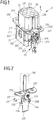
- Fig. 6
- eine Ansicht eines Erdungselements des Kontakteinsatzes;
- Fig. 7
- eine andere Ansicht des Kontakteinsatzes;
- Fig. 8
- eine Ansicht eines Kontakteinsatzes für ein Steckverbinderteil, nach einem anderen Ausführungsbeispiel;
- Fig. 9
- eine Ansicht eines Erdungselements des Kontakteinsatzes;
- Fig. 10
- eine andere Ansicht des Kontakteinsatzes;
- Fig. 11
- eine Ansicht eines wiederum anderen Ausführungsbeispiels eines Kontakteinsatzes;
- Fig. 12
- eine Ansicht eines wiederum anderen Ausführungsbeispiels eines Kontakteinsatzes;
- Fig. 13
- eine Ansicht eines Erdungselements des Kontakteinsatzes;
- Fig. 14
- eine schematische Ansicht zweier Steckverbinderteile, die steckend entlang einer Steckrichtung miteinander verbunden werden können:
- Fig. 15
- eine Ansicht eines wiederum anderen Ausführungsbeispiels eines Kontakteinsatzes;
- Fig. 16
- eine Ansicht des Kontakteinsatzes gemäß
Fig. 15 , in zusammengesetztem Zustand; - Fig. 17
- eine Ansicht eines wiederum anderen Ausführungsbeispiels eines Kontakteinsatzes;
- Fig. 18
- eine Ansicht des Kontakteinsatzes gemäß
Fig. 17 , in zusammengesetztem Zustand; - Fig. 19
- eine Ansicht eines wiederum anderen Ausführungsbeispiels eines Kontakteinsatzes;
- Fig. 20
- eine Ansicht des Kontakteinsatzes gemäß
Fig. 19 , in zusammengesetztem Zustand; - Fig. 21
- eine Ansicht eines wiederum anderen Ausführungsbeispiels eines Kontakteinsatzes;
- Fig. 22
- eine Ansicht des Kontakteinsatzes gemäß
Fig. 21 , in zusammengesetztem Zustand; und - Fig. 23
- eine gesonderte Ansicht eines Erdungselements des Kontakteinsatzes.
- Fig. 1
- a view of a contact insert for a connector part, which is not part of the invention;
- Fig. 2
- a view of a grounding element of the contact insert, which is not part of the invention;
- Fig. 3
- a view of an embodiment of a to the contact insert according to FIG
Figs. 1 and 2 complementary contact insert for a connector part, which is not part of the invention; - Fig. 4
- a view of a grounding element of the contact insert, which is not part of the invention;
- Fig. 5
- a view of a contact insert for a connector part, according to an embodiment;
- Fig. 6
- a view of a grounding element of the contact insert;
- Fig. 7
- another view of the contact insert;
- Fig. 8
- a view of a contact insert for a connector part, according to another embodiment;
- Fig. 9
- a view of a grounding element of the contact insert;
- Fig. 10
- another view of the contact insert;
- Fig. 11
- a view of yet another embodiment of a contact insert;
- Fig. 12
- a view of yet another embodiment of a contact insert;
- Fig. 13
- a view of a grounding element of the contact insert;
- Fig. 14
- a schematic view of two connector parts that can be plugged together along a plugging direction:
- Fig. 15
- a view of yet another embodiment of a contact insert;
- Fig. 16
- a view of the contact insert according to
Fig. 15 , in assembled condition; - Fig. 17
- a view of yet another embodiment of a contact insert;
- Fig. 18
- a view of the contact insert according to
Fig. 17 , in assembled condition; - Fig. 19
- a view of yet another embodiment of a contact insert;
- Fig. 20
- a view of the contact insert according to
Fig. 19 , in assembled condition; - Fig. 21
- a view of yet another embodiment of a contact insert;
- Fig. 22
- a view of the contact insert according to
Fig. 21 , in assembled condition; and - Fig. 23
- a separate view of a grounding element of the contact insert.
Jedes Steckverbinderteil 1, 3 weist ein Steckergehäuse 10, 30 auf, in dem jeweils ein Kontakteinsatz 2, 4 mit daran angeordneten Kontaktelementen aufgenommen ist. Über einen Kabelabgang 11, 31 ist jeweils ein Kabel 12, 32 an das Steckergehäuse 10, 30 angeschlossen und innerhalb des Steckergehäuses 10, 30 mit den Kontaktelementen des jeweils zugeordneten Kontakteinsatzes 2, 4 elektrisch verbunden.Each
Angemerkt sei bereits an dieser Stelle, dass die vorliegende Erfindung nicht nur bei Steckverbinderteilen mit händisch zu handhabenden Steckergehäusen einsetzbar ist, sondern beispielsweise auch bei an elektrischen Anlagen, beispielsweise einem Schaltschrank, vorgesehenen Steckverbindern verwendet werden kann, bei denen ein Kontakteinsatz beispielsweise an einer Gerätewand, beispielsweise einer Schaltschrankwand, festzulegen ist.It should be noted at this point that the present invention can be used not only with connector parts with manually operated connector housings, but can also be used, for example, with connectors provided on electrical systems, for example a switch cabinet, in which a Contact insert, for example, on a device wall, such as a control cabinet wall, is to be set.
Der Kontakteinsatz 2 weist einen Isolierkörper 20 auf, der aus einem elektrisch isolierenden (Kunststoff-) Material gefertigt ist. Der Isolierkörper 20 bildet einen Steckabschnitt 206 aus, der zum Verbinden zweier einander zugeordneter Steckverbinderteile 1, 3 mit einem Steckabschnitt 406 eines komplementären, in
An dem Steckabschnitt 206 sind Stecköffnungen 200 gebildet, in denen Kontaktelemente 22 angeordnet sind, die als Kontaktstifte ausgebildet sind und zum elektrischen Kontaktieren mit Kontaktelementen 42 in Form von Kontaktbuchsen innerhalb der Stecköffnung 400 des Steckabschnitts 406 des Kontakteinsatzes 4 dienen.
An einem unteren Abschnitt 203 des Isolierkörpers 20 ist ein Abdeckelement 21 angeordnet, das den unteren Abschnitt 203 mit einem Umgriffsabschnitt 210 umgreift und über Befestigungslaschen 211 - durch Eingriff von Rastelementen 204 an dem unteren Abschnitt 203 in Öffnungen 212 in den Befestigungslaschen 211 - formschlüssig an dem unteren Abschnitt 23 festgelegt ist (in
Quer zum Steckabschnitt 206 steht an einer Seite ein Befestigungsabschnitt 202 zum Befestigen des Kontakteinsatzes 2 innerhalb des zugeordneten Steckergehäuses 10 vor.A
Gegenüberliegend ist an dem Isolierkörper 20 ein Erdungselement 23 angeordnet, das in einer gesonderten Darstellung in
Das Erdungselement 23 weist Gehäusekontaktabschnitte 231 auf, die als Flanschabschnitte quer vom Steckabschnitt 206 vorstehen (wenn das Erdungselement 23 an den Isolierkörper 20 angesetzt ist) und Befestigungsöffnungen 232 tragen, über die eine Befestigung des Kontakteinsatzes 2 mit dem zugeordneten Steckergehäuse 10 hergestellt werden kann.The
An die Gehäusekontaktabschnitte 231 schließt ein Flächenabschnitt 233 an, in dem eine Befestigungsöffnung 235 zum Befestigen des Erdungselements 23 an dem Isolierkörper 20 mittels eines als Schraube ausgebildeten Befestigungselements 236 angeordnet ist und von dem hin zum Isolierkörper 20 Formschlusselemente 234 zum Eingriff in den Isolierkörper 20 und entgegengesetzt gerichtet Vorsprungselemente 238 vorstehen. Über die Formschlusselemente 234 wird das Erdungselement 23 lagerichtig zu dem Isolierkörper 20 festgelegt. Die Formschlusselemente 238 dienen demgegenüber dazu, beim Verdrehen des als Schraube ausgebildeten Befestigungselements 236 ein Mitdrehen einer Unterlegscheibe 239 (siehe
Über einen an den Flächenabschnitt 233 anschließenden Kontaktabschnitt 237 kann eine Erdungsleitung zum Beispiel mittels Verkrimpen an das Erdungselement 23 angeschlossen werden.A grounding line can be connected to the
Alternativ kann eine Erdungsleitung über das als Schraube ausgebildete Befestigungselement 236 an dem Erdungselement 23 festgelegt werden.Alternatively, a grounding line can be fixed to the
Einstückig an das Erdungselement 23 ist ein Erdungskontaktelement 230 angeformt, das sich, wie aus
Das Erdungskontaktelement 230 hat eine Doppelfunktion. Zum einen dient das Erdungskontaktelement 230 dazu, beim steckenden Verbinden des dem Kontakteinsatz 2 zugeordneten Steckverbinderteils 1 mit dem dem Kontakteinsatz 4 (siehe
Bei in das Steckergehäuse 10 eingesetztem Kontakteinsatz 2 liegen die Gehäusekontaktabschnitte 231 des Erdungselements 23 in elektrisch kontaktierender Weise innenseitig an dem Steckergehäuse 10 an, sodass bei einem aus Metall gefertigten Steckergehäuse 10 eine Erdung an dem Steckergehäuse 10 erfolgt und somit das Steckergehäuse 10 sich auf einem Erdpotenzial befindet. Durch unmittelbare Befestigung der Gehäusekontaktabschnitte 231 über die Befestigungsöffnungen 232 an dem Steckergehäuse 10 wird hierbei eine flächige Anlage mit dem Steckergehäuse 10 sichergestellt, sodass eine elektrische Kontaktierung gewährleistet ist.When the
Die erdende Kontaktierung mit dem komplementären Kontakteinsatz 4 erfolgt über das Erdungselement 230, das bei steckendem Verbinden der Steckverbinderteile 1, 3 auf das Erdungskontaktelement 430 innenseitig der Stecköffnung 400 des Steckabschnitts 406 des Kontakteinsatzes 4 aufgleitet und darüber elektrisch kontaktiert.The grounding contact with the
Der in
Das in
Das an das Erdungselement 43 einstückig angeformte Erdungskontaktelement 430 kommt, bei an dem Isolierkörper 40 angeordnetem Erdungselement 43, innenseitig der Stecköffnung 400 im Bereich des Kodierelements 401, nämlich zwischen längs entlang der Steckrichtung E erstreckten Stegen des Kodierelements 401, zu liegen und ist somit Bestandteil des Kodierelements 401. Bei steckendem Verbinden des Kontakteinsatzes 4 mit dem Kontakteinsatz 2 gleitet das Erdungskontaktelement 230 des Kontakteinsatzes 2 auf das Erdungskontaktelement 430 des Kontakteinsatzes 4 auf und stellt darüber eine erdende, elektrische Verbindung zwischen den Kontakteinsätzen 2, 4 her.When the
Bei einem in
An den Steckabschnitt 206 schließt ein unterer Abschnitt 203 an, von dem, quer zur Steckrichtung E, im Übergangsbereich zu dem Steckabschnitt 206 Befestigungsabschnitte 202 in Form von Flanschen quer zur Steckrichtung E vorstehen. An den Befestigungsabschnitten 202 sind Befestigungsöffnungen 207 gebildet, über die der Kontakteinsatz 2 innerhalb des zugeordneten Steckverbindergehäuses 10 befestigt werden kann.A
Der Isolierkörper 20 besteht aus einem elektrisch isolierenden (Kunststoff-)Material und ist, bei dem dargestellten Ausführungsbeispiel, mittels Spritzgießen gefertigt. Ein Erdungselement 24, wie es in einer gesonderten Darstellung in
Das Erdungselement 24 weist einen Verbindungsabschnitt 240 nach Art eines Strombalkens auf, an dem einerseits der Gehäusekontaktabschnitt 242 und andererseits ein Kontaktabschnitt 245 zum Kontaktieren mit einem zugeordneten Erdungskontaktelement 220 angeordnet ist. Der über einen abgewinkelten Abschnitt 241 mit dem Verbindungsabschnitt 240 verbundene Gehäusekontaktabschnitt 242 trägt eine Öffnung 243, die mit einer zugeordneten Befestigungsöffnung 207 des zugeordneten Befestigungsabschnitts 202 des Isolierkörpers 20 fluchtet, wie dies aus
Ist der Kontakteinsatz 2 in das zugeordnete Steckergehäuse 10 eingesetzt, so ist über die elektrisch kontaktierende Anlage des Gehäusekontaktabschnitts 242 an dem Steckergehäuse 10 und die elektrische Verbindung des Kontaktabschnitts 245 mit dem Erdungskontaktelement 220 das Steckergehäuse 10 elektrisch mit dem Erdungskontaktelement 220 verbunden, wobei an das Erdungskontaktelement 220 eine Erdungsleitung angeschlossen sein kann. Bei steckendem Verbinden des Kontakteinsatzes 2 mit einem zugeordneten, komplementären Kontakteinsatz eines Gegensteckverbinderteils kontaktiert das Erdungskontaktelement 220 zudem mit einem zugeordneten Gegenkontaktelement, sodass eine Erdung mit dem Gegensteckverbinderteil hergestellt wird.If the
Das Erdungselement 24 kann mit seinen Abschnitten 240-242, 244, 245 beispielsweise als einstückiges Blechbiegeteil hergestellt sein. Zum Fertigen des Isolierkörpers 20 wird das Erdungselement 24 in ein Spritzgusswerkzeug zum Herstellen des Isolierkörpers 20 eingelegt und beim Spritzgießen des Isolierkörpers 20 von dem Material des Isolierkörpers 20 umspritzt.The
Bei einem anderen Ausführungsbeispiel eines Kontakteinsatzes 4, wie er in
Das Erdungselement 44 weist einen Verbindungsabschnitt 440 auf, der den Gehäusekontaktabschnitt 442 mit einem Kontaktabschnitt 445 verbindet, über den das Erdungselement 44 elektrisch mit einem zugeordneten Erdungskontaktelement 420 verbunden ist. Über das Erdungselement 44 wird somit eine elektrische Verbindung zwischen dem Steckergehäuse 30 und dem Erdungskontaktelement 420 hergestellt, wobei an das Erdungskontaktelement 420 wiederum eine Erdungsleitung angeschlossen sein kann und bei steckendem Verbinden mit einem zugeordneten Gegensteckverbinderteil eine elektrische Kontaktierung mit dem Gegensteckverbinderteil und somit eine gemeinsame Erdung erfolgt.The
Die Befestigungsabschnitte 402 unterseitig des Steckabschnitts 406 sind bei dem dargestellten Ausführungsbeispiel als Absätze am Übergang zu einem unteren Abschnitt 403 ausgebildet. Im Bereich eines dieser Befestigungsabschnitte 402 kommt der Gehäusekontaktabschnitt 442 des Erdungselements 44 zu liegen, wie dies aus
Bei dem dargestellten Ausführungsbeispiel ist das Erdungselement 44 als Metallspritzgussteil gefertigt. Die Fertigung des Erdungselements 44 kann bei bereits vorliegendem Isolierkörper 40 erfolgen, indem beispielsweise eine flüssige Zinnlegierung oder eine andere Metalllegierung mit niedriger Schmelztemperatur in eine dafür vorgesehene Öffnung an dem Isolierkörper 40 eingespritzt wird.In the illustrated embodiment, the
Bei einem in
Das Abdeckelement 21 weist einen Bodenabschnitt 213 mit darin gebildeten Öffnungen 214 zum Aufnehmen von Kontaktelementen 22 auf. An den Öffnungen 214 sind Stützabschnitte 215 ausgebildet, die nach Art von Stiften von dem Bodenabschnitt 213 vorstehen und zum Abstützen der Kontaktelemente 22 dienen.The
Das Abdeckelement 21 weist einen Umgriffsabschnitt 210 auf, der in angesetzter Stellung den unteren Abschnitt 203 umgreift, wie dies auch in
Das Erdungselement 25 weist einen quer erstreckten, balkenförmigen Verbindungsabschnitt 250 auf, von dem nach oben hin in Richtung eines Steckabschnitts 206 eine Kontaktfahne 251 vorsteht und an dem seitlich Gehäusekontaktabschnitte 252 angeordnet sind. Das Erdungselement 25 ist mit seinen Verbindungsabschnitten 250 in eine Nut 217 in dem Bodenabschnitt 213 eingesetzt und liegt mit den Gehäusekontaktabschnitten 252 in Öffnungen 216 in dem Umgriffsabschnitt 210 derart ein, dass die Gehäusekontaktabschnitte 252 seitlich von dem Abdeckelement 21 in Richtung des umgebenden Steckergehäuses 10 vorstehen.The
Das Erdungskontaktelement 220 ist in eine Öffnung 214 in dem Bodenabschnitt 213 des Abdeckelements 21 eingesetzt und steht elektrisch kontaktierend mit der Kontaktfahne 251 des Erdungselements 25 in Anlage. Bei in das Steckergehäuse 10 eingesetztem Kontakteinsatz 2 ist das Erdungselement 25 über die Gehäusekontaktabschnitte 252 zudem mit dem Steckergehäuse 10 kontaktiert, sodass das Steckergehäuse 10 mit dem Erdungskontaktelement 220 elektrisch verbunden ist.The
An das Erdungskontaktelement 220 kann wiederum eine Erdungsleitung angeschlossen sein, und zusätzlich kontaktiert das Erdungskontaktelement 220 bei steckendem Verbinden mit einem zugeordneten Gegensteckverbinderteil mit einem Gegenkontaktelement des Gegensteckverbinderteils, sodass darüber ein gemeinsames Erdpotential zwischen den Steckverbinderteilen besteht.A grounding line can in turn be connected to the
Das Ausführungsbeispiel gemäß
Im Unterschied zu dem Ausführungsbeispiel gemäß
Zum Herstellen wird das Erdungselement 25 in das Spritzgusswerkzeug zum Herstellen des Abdeckelements 21 eingelegt und beim Spritzgießen des Abdeckelements 21 mit dem Material des Abdeckelements 21 umspritzt.For production, the
Im Übrigen soll vollumfänglich auf die vorangehenden Ausführungen zum Ausführungsbeispiel gemäß
Bei den Ausführungsbeispielen gemäß
Über Öffnungen 214 in dem Abdeckelement 21 können elektrische Leitungen an die Kontaktelemente 22 und eine Erdungsleitung an das Erdungskontaktelement 220 angeschlossen sein.Electrical lines can be connected to the
An dem Isolierkörper 20 ist ein Erdungselement 26 angeordnet, das mit einem Gehäusekontaktabschnitt 261 in Form eines Flansches an einen Befestigungsabschnitt 202 in Form einer Stufe an dem Isolierkörper 20 angesetzt ist und Befestigungsstellen in Form von Befestigungsöffnungen 262 aufweist, über die der Kontakteinsatz 2 innerhalb eines Steckergehäuses 10 (siehe
Über einen mehrfach umgebogenen Verbindungsabschnitt 260 ist der Gehäusekontaktabschnitt 261 mit Kontaktabschnitten 263 in Form von Federzungen verbunden, die eine Aufnahme für das Erdungskontaktelement 220 schaffen und in zusammengesetzter Stellung (
Das Erdungskontaktelement 220 ist mit dem Isolierkörper 20 verrastet, sodass ein Ende des Erdungskontaktelements 220 in den Bereich des Steckabschnitts 206 des Isolierkörpers 20 hineinragt und somit mit einem zugeordneten Gegensteckverbinderteil verbunden werden kann. Das Erdungselement 26 ist an dem Isolierkörper 20 angeordnet und umgreift mit einem Verbindungsabschnitt 260 einen Körperabschnitt 208 des Isolierkörpers 20, an dem Kontaktelemente 22 angeordnet sind, sodass über die Kontaktabschnitte 263 das Erdungskontaktelement 220 in zentraler Position an dem Isolierkörper 20 kontaktiert ist.The
Bei einem in
Von jedem Gehäusekontaktabschnitt 271 erstrecken sich zwei Verbindungsabschnitte 270, die zu dem zugeordneten Gehäusekontaktabschnitt 271 abgewinkelt und mehrfach umgebogen sind und Kontaktabschnitte 273 in Form von Kontaktfahnen tragen, über die ein zentral an dem Isolierkörper 20 angeordnetes Erdungskontaktelement 220 elektrisch kontaktiert ist. Die Verbindungsabschnitte 270 umgreifen Körperabschnitte 208 des Isolierkörpers 20, an denen Kontaktelemente 22 angeordnet sind.From each
Bei zusammengesetztem Kontakteinsatz 2 (
Der Isolierkörper 20 bildet wiederum einen Steckabschnitt 206 aus, über den der Kontakteinsatz 2 mit einem zugeordneten Gegensteckverbinderteil entlang einer Steckrichtung E verbunden werden kann, um die Kontaktelemente 22 und das Erdungskontaktelement 220 elektrisch zu kontaktieren. Die Erdungselemente 27 sind hierbei an einem unteren Abschnitt 203 an einer dem Steckabschnitt 106 abgewandten Seite des Isolierkörpers 20 angeordnet.The insulating
Bei zusammengesetztem Kontakteinsatz 2 ist ein Abdeckelement 21 an den Isolierkörper 20 angesetzt (siehe
Bei einem in
Ein jedes Erdungselement 28 weist zwei mehrfach umgebogene, zu dem Gehäusekontaktabschnitt 281 abgewinkelte Verbindungsabschnitte 280 auf, die jeweils einen Kontaktabschnitt 283 in Form einer gekrümmten Kontaktnase tragen. Die Kontaktabschnitte 283 der Erdungselemente 28 nehmen bei zusammengesetztem Kontakteinsatz 2 das Erdungskontaktelement 220 zwischen sich auf und kontaktieren somit das Erdungskontaktelement 220.Each grounding
Die Verbindungsabschnitte 280 umgreifen jeweils einen zugeordneten Körperabschnitt 208 des Isolierkörpers 22, um mit dem zentral an dem Isolierkörper 20 angeordneten Erdungskontaktelement 220 elektrisch zu kontaktieren.The connecting
Bei zusammengesetztem Kontakteinsatz 2 ist ein Abdeckelement 21 an den Isolierkörper 20 angesetzt, wie dies in
Bei einem in
Von dem Gehäusekontaktabschnitt 291 erstreckt sich ein C-förmiger Verbindungsabschnitt 290, der an von dem Gehäusekontaktabschnitt 291 abliegenden, abgewinkelten Enden 293 fest mit einem Erdungskontaktelement 220 verbunden ist, zum Beispiel über eine Klemmverbindung, eine Schraub- oder Nietverbindung oder eine Löt- oder Schweißverbindung.A C-shaped connecting
Bei diesem Ausführungsbeispiel ist das Erdungskontaktelement 220 somit fest mit dem Erdungselement 29 verbunden, sodass durch Ansetzen des Erdungselements 29 an den Isolierkörper 20 auch das Erdungskontaktelement 220 an dem Isolierkörper 20 platziert wird.In this exemplary embodiment, the
In angesetzter Stellung umgreift das Erdungselement 29 mit seinem C-förmigen Verbindungsabschnitt 290 einen Körperabschnitt 208 des Isolierkörpers 20, an dem Kontaktelemente 22 angeordnet sind.In the attached position, the
An dem Verbindungsabschnitt 290 ist, an einer dem Gehäusekontaktabschnitt 291 zugewandten Seite, ein Befestigungselement 296 in Form einer Schraube angeordnet, das in eine Gewindeöffnung 295 des Verbindungsabschnitts 290 eingeschraubt ist. Eine Mutter 297 steht mit dem Befestigungselement 296 in Form der Schraube in Gewindeeingriffe und ist zudem über Anschlagelemente 294 gegenüber dem Verbindungsabschnitt 290 abgestützt, sodass bei einem Verdrehen des Befestigungselements 296 in Form der Schraube die Mutter 297 nicht mit bewegt werden kann.On the connecting
Über das Befestigungselement 296 kann eine Erdungsleitung an das Erdungselement 29 angeschlossen werden, um auf diese Weise eine Erdung an dem Erdungselement 29 und darüber auch an einem Steckergehäuse 10, in dem der Kontakteinsatz 2 montiert ist, bereitzustellen.A grounding line can be connected to the
An den Isolierkörper 20 ist ein Abdeckelement 21 angesetzt, das Öffnungen 214 aufweist, über die elektrische Leitungen an die Kontaktelemente 22 angeschlossen sein können.A
Der der Erfindung zugrunde liegende Gedanke ist nicht auf die vorangehend geschilderten Ausführungsbeispiele beschränkt, sondern lässt sich grundsätzlich auch in gänzlich anders gearteter Weise verwirklichen.The idea on which the invention is based is not restricted to the exemplary embodiments described above, but can in principle also be implemented in a completely different manner.
Ein Steckverbinderteil der hier beschriebenen Art kann in modularer Weise mit unterschiedlichen Kontakteinsätzen bestückt werden, wobei über ein Erdungselement eine elektrische Kontaktierung und Erdung eines (elektrisch leitfähigen) Steckergehäuses des Steckverbinderteils erfolgt.A connector part of the type described here can be fitted with different contact inserts in a modular manner, with electrical contacting and grounding of an (electrically conductive) connector housing of the connector part taking place via a grounding element.
Ein solches Steckverbinderteil kann händisch mit einem zugeordneten Gegensteckverbinderteil verbunden werden, kann aber auch Bestandteil einer elektrischen Anlage, zum Beispiel eines Schaltschranks, sein.Such a connector part can be manually connected to an assigned mating connector part, but it can also be part of an electrical system, for example a switch cabinet.
- 11
- SteckverbinderteilConnector part
- 1010
- SteckergehäuseConnector housing
- 1111th
- KabelabgangCable outlet
- 1212th
- Kabelcable
- 22
- KontakteinsatzContact insert
- 2020th
- IsolierkörperInsulating body
- 200200
- StecköffnungPlug-in opening
- 201201
- KodierelementCoding element
- 202202
- BefestigungsabschnittFastening section
- 203203
- Unterer AbschnittLower section
- 204204
- RastelementLocking element
- 205205
- AnlagestegContact bridge
- 206206
- SteckabschnittPlug-in section
- 207207
- BefestigungsstelleAttachment point
- 208208
- Körperabschnitt (Grundkörper)Body section (main body)
- 2121
- AbdeckelementCover element
- 210210
- UmgriffsabschnittWrap-around section
- 211211
- BefestigungslascheFastening tab
- 212212
- RastöffnungLocking opening
- 213213
- BodenabschnittFloor section
- 214214
- Öffnungopening
- 215215
- StützabschnittSupport section
- 216216
- Öffnungopening
- 217217
- NutGroove
- 2222nd
- KontaktelementContact element
- 220220
- ErdungskontaktelementEarthing contact element
- 2323
- ErdungselementGrounding element
- 230230
- ErdungskontaktelementEarthing contact element
- 231231
- GehäusekontaktabschnittHousing contact section
- 232232
- BefestigungsöffnungMounting hole
- 233233
- FlächenabschnittArea segment
- 234234
- FormschlusselementForm-fit element
- 235235
- BefestigungsöffnungMounting hole
- 236236
- Befestigungselement (Schraube)Fastening element (screw)
- 237237
- KontaktabschnittContact section
- 238238
- VorsprungselementeProtruding elements
- 239239
- UnterlegscheibeWasher
- 2424
- ErdungselementGrounding element
- 240240
- VerbindungsabschnittConnection section
- 241241
- Abgewinkelter AbschnittAngled section
- 242242
- GehäusekontaktabschnittHousing contact section
- 243243
- BefestigungsöffnungMounting hole
- 244244
- Vorstehender AbschnittSection above
- 245245
- KontaktabschnittContact section
- 246246
- Öffnungopening
- 2525th
- ErdungselementGrounding element
- 250250
- VerbindungsabschnittConnection section
- 251251
- KontaktfahneContact flag
- 252252
- GehäusekontaktabschnittHousing contact section
- 2626th
- ErdungselementGrounding element
- 260260
- VerbindungsabschnittConnection section
- 261261
- GehäusekontaktabschnittHousing contact section
- 262262
- BefestigungsöffnungMounting hole
- 263263
- KontaktabschnittContact section
- 2727
- ErdungselementGrounding element
- 270270
- VerbindungsabschnittConnection section
- 271271
- GehäusekontaktabschnittHousing contact section
- 272272
- BefestigungsöffnungMounting hole
- 273273
- KontaktabschnittContact section
- 2828
- ErdungselementGrounding element
- 280280
- VerbindungsabschnittConnection section
- 281281
- GehäusekontaktabschnittHousing contact section
- 282282
- BefestigungsöffnungMounting hole
- 283283
- KontaktabschnittContact section
- 2929
- ErdungselementGrounding element
- 290290
- VerbindungsabschnittConnection section
- 291291
- GehäusekontaktabschnittHousing contact section
- 292292
- BefestigungsöffnungMounting hole
- 293293
- KontaktabschnittContact section
- 294294
- AnschlagelementStop element
- 295295
- BefestigungsöffnungMounting hole
- 296296
- BefestigungselementFastener
- 297297
- Muttermother
- 33
- SteckverbinderteilConnector part
- 3030th
- SteckergehäuseConnector housing
- 3131
- KabelabgangCable outlet
- 3232
- Kabelcable
- 44th
- KontakteinsatzContact insert
- 4040
- IsolierkörperInsulating body
- 400400
- StecköffnungPlug-in opening
- 401401
- KodierelementCoding element
- 402402
- BefestigungsabschnittFastening section
- 403403
- Unterer AbschnittLower section
- 404404
- RastelementLocking element
- 406406
- SteckabschnittPlug-in section
- 407407
- KodierelementCoding element
- 4141
- AbdeckelementCover element
- 410410
- UmgriffsabschnittWrap-around section
- 411411
- BefestigungslascheFastening tab
- 412412
- RastöffnungLocking opening
- 4242
- KontaktelementContact element
- 420420
- ErdungskontaktelementEarthing contact element
- 4343
- ErdungselementGrounding element
- 430430
- ErdungskontaktelementEarthing contact element
- 431431
- GehäusekontaktabschnittHousing contact section
- 432432
- BefestigungsöffnungMounting hole
- 433433
- FlächenabschnittArea segment
- 434434
- FormschlusselementForm-fit element
- 435435
- BefestigungsöffnungMounting hole
- 436436
- Befestigungselement (Schraube)Fastening element (screw)
- 437437
- KontaktabschnittContact section
- 438438
- VorsprungselementeProtruding elements
- 439439
- UnterlegscheibeWasher
- 4444
- ErdungselementGrounding element
- 440440
- VerbindungsabschnittConnection section
- 442442
- GehäusekontaktabschnittHousing contact section
- 443443
- BefestigungsöffnungMounting hole
- 445445
- KontaktabschnittContact section
- EE.
- SteckrichtungMating direction
Claims (11)
- Assembly for a plug-in connector part (1, 3), with a plug housing (10, 30) made from metal, and with a contact insert (2, 4) which is connectable to the plug housing (10, 30) and has an insulating body (20, 40) which is composed of an electrically insulating material and which forms a plug-in portion (206, 406), which is connectable in a plug-in manner along a plug-in direction (E) to a mating plug-in connector part (3, 1), and is arranged on the at least one electric contact element (22, 42) for making electrical contact with an associated mating contact element (42, 22) of the mating plug-in connector part (3, 1), and with an earthing element (23, 24, 25, 26, 27, 28, 29, 43, 44) which is arranged on the insulating body (20, 40) and which has a housing contact portion (231, 242, 252, 261, 271, 281, 291, 431, 442) and is electrically connected to an earthing contact element (220, 230, 420, 430), which is arranged on the plug-in portion (206, 406), for making earthing contact with the mating plug-in connector part (4, 2), wherein the housing contact portion (231, 242, 252, 261, 271, 281, 291, 431, 442) is designed to make electrical contact with the plug housing (10, 30) when the contact insert (2, 4) is connected to the plug housing (10, 30), characterized in that the housing contact portion (242, 261, 271, 281, 291, 442) is arranged in the region of a fastening portion (202, 402) of the insulating body (20, 40), said fastening portion extending transversely with respect to the plug-in direction (E) and being able to be brought into operative contact with the plug housing (10, 30) in a supporting manner, and in that the earthing contact element (220, 420) is surrounded by the plug-in portion (206, 406).
- Assembly according to Claim 1, characterized in that the insulating body (20, 40) is formed integrally.
- Assembly according to Claim 1 or 2, characterized in that the earthing contact element (220, 230, 420, 430) extends along the plug-in direction (E) and, upon plugging-in connection along the plug-in direction (E), makes contact in an earthing manner with the mating plug-in connector part (3, 1).
- Assembly according to one of Claims 1 to 3, characterized in that the housing contact portion (231, 242, 261, 271, 281, 291, 431, 442) extends flat along a plane extending transversely with respect to the plug-in direction (E).
- Assembly according to one of the preceding claims, characterized in that the housing contact portion (231, 242, 261, 271, 281, 291, 431, 442) has at least one fastening point (232, 243, 262, 272, 282, 292, 432, 443) for mechanically fastening the contact insert (2, 4) to the plug housing (10, 30).
- Assembly according to one of Claims 1 to 5, characterized in that the earthing contact element (220, 420) is arranged as an element which is separate from the earthing element (24, 25, 26, 27, 28, 29, 44) within the plug-in portion (206, 406).
- Assembly according to Claim 6, characterized in that the earthing element (220, 420) has a contact portion (245, 263, 273, 283, 293, 445) for electrical connection to the earthing contact element (220, 420), which contact portion is connected to the housing contact portion (242, 261, 271, 281, 291, 442) via a connecting portion (240, 260, 270, 280, 290, 440).
- Assembly according to Claim 7, characterized in that the contact portion (245, 263, 273, 283, 293, 445) is angled in relation to the connection portion (240, 260, 270, 280, 290, 440) and/or the connecting portion (240, 260, 270, 280, 290, 440) is angled in relation to the housing contact portion (242, 261, 271, 281, 291, 443).
- Assembly according to Claim 7 or 8, characterized in that the connecting portion (260, 270, 280, 290) engages around a body portion (208) of the insulating body (20).
- Assembly according to one of Claims 7 to 9, characterized in that the contact portion (263, 273, 283, 293) is formed in an elastically resilient manner and lies in an electrically contacting manner against the earthing contact element (220).
- Assembly according to one of Claims 7 to 10, characterized in that two earthing elements (27, 28) are arranged on the insulating body (20) with a respective housing contact portion (271, 281) and a contact portion (273, 283), which is connected to the housing contact portion (271, 281) via a connecting portion (270, 280), said earthing elements together making contact with the earthing element (220).
Applications Claiming Priority (2)
| Application Number | Priority Date | Filing Date | Title |
|---|---|---|---|
| DE102017108162.3A DE102017108162A1 (en) | 2017-04-18 | 2017-04-18 | Assembly for a connector part with a contact insert and a grounding element |
| PCT/EP2018/059882 WO2018192962A1 (en) | 2017-04-18 | 2018-04-18 | Assembly for a plug connector part with a contact insert and a grounding element |
Publications (2)
| Publication Number | Publication Date |
|---|---|
| EP3613110A1 EP3613110A1 (en) | 2020-02-26 |
| EP3613110B1 true EP3613110B1 (en) | 2021-11-17 |
Family
ID=62027990
Family Applications (1)
| Application Number | Title | Priority Date | Filing Date |
|---|---|---|---|
| EP18719124.2A Active EP3613110B1 (en) | 2017-04-18 | 2018-04-18 | Assembly for a plug connector part with a contact insert and a grounding element |
Country Status (5)
| Country | Link |
|---|---|
| EP (1) | EP3613110B1 (en) |
| JP (1) | JP7174713B2 (en) |
| CN (1) | CN110546823B (en) |
| DE (2) | DE102017108162A1 (en) |
| WO (1) | WO2018192962A1 (en) |
Families Citing this family (6)
| Publication number | Priority date | Publication date | Assignee | Title |
|---|---|---|---|---|
| KR102546497B1 (en) | 2018-09-13 | 2023-06-23 | 하르팅 일렉트릭 슈티프퉁 운트 코우. 카게 | Plug-in connector with ground terminal area |
| DE102019101822B4 (en) * | 2019-01-25 | 2022-03-31 | Amphenol Tuchel Industrial GmbH | safety plug |
| BE1027151B1 (en) * | 2019-03-29 | 2020-10-26 | Phoenix Contact Gmbh & Co | Connector with a contacting element designed as a cast part |
| DE102019132167A1 (en) * | 2019-11-27 | 2021-05-27 | Connaught Electronics Ltd. | Electrical connector for connection to a vehicle camera, as well as arrangement |
| CN114914758A (en) * | 2021-02-09 | 2022-08-16 | 哈廷电子有限公司及两合公司 | Insert for connector |
| CN117895264A (en) * | 2022-10-08 | 2024-04-16 | 哈廷电子基金会两合公司 | Assembly of plug-in connector parts, plug-in connector parts and system |
Citations (9)
| Publication number | Priority date | Publication date | Assignee | Title |
|---|---|---|---|---|
| US3723942A (en) | 1972-03-03 | 1973-03-27 | Arrow Hart Inc | Grounding clip electric receptacles |
| US4291930A (en) | 1979-09-12 | 1981-09-29 | International Telephone And Telegraph Corporation | Ground lug for electrical connector |
| EP0475416A1 (en) | 1990-09-13 | 1992-03-18 | Hirose Electric Co., Ltd. | Electrical connector |
| DE9207738U1 (en) | 1992-06-10 | 1992-08-20 | Interconnectron Gmbh, 8360 Deggendorf, De | |
| DE19528678C1 (en) | 1995-07-19 | 1997-01-23 | Ifm Electronic Gmbh | Panel mounting plug with conductive shell connected to and integral with earth pin |
| DE102013108383A1 (en) | 2013-08-05 | 2015-02-05 | Harting Electric Gmbh & Co. Kg | connector module |
| DE202016100412U1 (en) | 2016-01-28 | 2016-02-16 | Phoenix Contact Connector Technology Gmbh | Electrical connector |
| EP3276755A1 (en) | 2016-07-28 | 2018-01-31 | LQ Mechatronik-Systeme GmbH | Plug part for a shielded plug-in unit |
| EP3312940A1 (en) | 2016-10-20 | 2018-04-25 | Phoenix Contact GmbH & Co. KG | Contact insert for a connector part |
Family Cites Families (11)
| Publication number | Priority date | Publication date | Assignee | Title |
|---|---|---|---|---|
| US4362350A (en) * | 1980-06-09 | 1982-12-07 | International Telephone And Telegraph Corporation | Contact retention assembly |
| DE8111418U1 (en) * | 1981-04-15 | 1981-11-05 | Harting Elektronik Gmbh, 4992 Espelkamp | Connection distributor |
| DE3369436D1 (en) * | 1982-05-28 | 1987-02-26 | Harting Elektronik Gmbh | Distributing connector |
| JP3025924B2 (en) * | 1991-11-18 | 2000-03-27 | モレックス インコーポレーテッド | Electrical connector |
| JP2717360B2 (en) * | 1994-08-17 | 1998-02-18 | 日本航空電子工業株式会社 | Connector protection circuit structure |
| US7597562B2 (en) * | 2005-01-28 | 2009-10-06 | Amphenol-Tuchel Electronics Gmbh | Plug-in connector |
| DE202006003204U1 (en) | 2006-03-01 | 2006-05-11 | Harting Electronics Gmbh & Co. Kg | Electric contact |
| FR2951587A1 (en) * | 2009-10-15 | 2011-04-22 | Hypertac Sa | ELECTRICAL CONNECTOR ELEMENT, AND ELECTRICAL CONNECTOR COMPRISING SUCH A ELEMENT |
| DE102010022690B4 (en) | 2010-06-04 | 2012-04-12 | Harting Electric Gmbh & Co. Kg | Electrical connector with PE contact |
| DE102012016725B4 (en) | 2012-08-22 | 2014-07-31 | Amphenol-Tuchel Electronics Gmbh | Protective conductor connection and plug connector with a protective conductor connection for at least one cable |
| CN106129725B (en) * | 2016-08-29 | 2019-07-26 | 中航光电科技股份有限公司 | Lightning-protection connector component, lightning-protection connector and metal wire clamp |
-
2017
- 2017-04-18 DE DE102017108162.3A patent/DE102017108162A1/en active Pending
-
2018
- 2018-04-18 CN CN201880025968.6A patent/CN110546823B/en active Active
- 2018-04-18 WO PCT/EP2018/059882 patent/WO2018192962A1/en unknown
- 2018-04-18 EP EP18719124.2A patent/EP3613110B1/en active Active
- 2018-04-18 JP JP2019556694A patent/JP7174713B2/en active Active
- 2018-04-18 DE DE202018006882.9U patent/DE202018006882U1/en active Active
Patent Citations (9)
| Publication number | Priority date | Publication date | Assignee | Title |
|---|---|---|---|---|
| US3723942A (en) | 1972-03-03 | 1973-03-27 | Arrow Hart Inc | Grounding clip electric receptacles |
| US4291930A (en) | 1979-09-12 | 1981-09-29 | International Telephone And Telegraph Corporation | Ground lug for electrical connector |
| EP0475416A1 (en) | 1990-09-13 | 1992-03-18 | Hirose Electric Co., Ltd. | Electrical connector |
| DE9207738U1 (en) | 1992-06-10 | 1992-08-20 | Interconnectron Gmbh, 8360 Deggendorf, De | |
| DE19528678C1 (en) | 1995-07-19 | 1997-01-23 | Ifm Electronic Gmbh | Panel mounting plug with conductive shell connected to and integral with earth pin |
| DE102013108383A1 (en) | 2013-08-05 | 2015-02-05 | Harting Electric Gmbh & Co. Kg | connector module |
| DE202016100412U1 (en) | 2016-01-28 | 2016-02-16 | Phoenix Contact Connector Technology Gmbh | Electrical connector |
| EP3276755A1 (en) | 2016-07-28 | 2018-01-31 | LQ Mechatronik-Systeme GmbH | Plug part for a shielded plug-in unit |
| EP3312940A1 (en) | 2016-10-20 | 2018-04-25 | Phoenix Contact GmbH & Co. KG | Contact insert for a connector part |
Non-Patent Citations (5)
| Title |
|---|
| "HARTING Industrie-Steckverbinder Han®", PRODUKT BROSCHURE, 27 February 2015 (2015-02-27), XP055955987 |
| ANONYMOUS: "Mehrpolige Steckverbinder für industrielle Anwen- dung CN .16", ILME KATALOG, 1 April 2016 (2016-04-01), XP055956075, [retrieved on 20220830] |
| ANONYMOUS: "New products 2012 - Supplement to CN .12 catalogue", ILME KATALOG, 1 January 2012 (2012-01-01), XP055956076, [retrieved on 20220830] |
| ANONYMOUS: "New products 2012 - Supplement to CN .12 catalogue", ILME KATALOG, 1 January 2012 (2012-01-01), XP055956077, [retrieved on 20220830] |
| HARTING: "Han® K 4/4", DATA SHEET 0345, 27 March 2007 (2007-03-27), pages 1 - 2, XP055955976 |
Also Published As
| Publication number | Publication date |
|---|---|
| JP7174713B2 (en) | 2022-11-17 |
| DE102017108162A1 (en) | 2018-10-18 |
| CN110546823B (en) | 2021-03-02 |
| JP2020518099A (en) | 2020-06-18 |
| WO2018192962A1 (en) | 2018-10-25 |
| EP3613110A1 (en) | 2020-02-26 |
| DE202018006882U1 (en) | 2024-01-18 |
| CN110546823A (en) | 2019-12-06 |
Similar Documents
| Publication | Publication Date | Title |
|---|---|---|
| EP3613110B1 (en) | Assembly for a plug connector part with a contact insert and a grounding element | |
| EP3719933B1 (en) | Connector device with at least one connector | |
| EP3312940B1 (en) | Contact insert for a connector part | |
| EP3433907B1 (en) | A connector for connecting to a mating connector | |
| EP2107648B1 (en) | Connector with a shielding-screen support | |
| DE102012110232B4 (en) | Connection device for power transmission in the motor vehicle sector | |
| DE1615001B2 (en) | ELECTRIC CONNECTOR | |
| EP2823536B1 (en) | Plug connector comprising a protective conductor bridge | |
| EP2366212A1 (en) | Electric multiple distributor | |
| EP1728414B1 (en) | Device provided with an electric motor and a main printed circuit board and mounting method | |
| WO2007113030A1 (en) | Connection module for connecting a control unit or similar to a drive unit | |
| DE102005012441A1 (en) | Electrical connector and method of making an electrical connector | |
| EP1306933B1 (en) | Guiding system for contact plug | |
| EP3123564B1 (en) | Electronics box with a printed circuit board and an electrical component part, and with a contact-making device | |
| EP2580823A1 (en) | Attachable plug-type connector | |
| EP2515388A1 (en) | Electric heating device | |
| EP2200125B1 (en) | Shielded connector | |
| DE10202920A1 (en) | Electrical pluggable connector e.g. for motor vehicle passenger restraint system, has contact springs electrically joined to electrical cable for lockably receiving plug | |
| EP2543116B1 (en) | Jumper bridge | |
| EP1091457B1 (en) | Electrical connector element and system | |
| EP2673848B1 (en) | Connector for electrically direct contacting of a printed circuit | |
| EP1720222B1 (en) | Electrical connector, particularly for airbag ignition systems | |
| EP2648285B1 (en) | Plug connector to be mounted in an opening of a housing | |
| EP3656021B1 (en) | Control device with shielding | |
| EP3504760B1 (en) | Multi-contact connector with integrated short-circuit element |
Legal Events
| Date | Code | Title | Description |
|---|---|---|---|
| STAA | Information on the status of an ep patent application or granted ep patent |
Free format text: STATUS: UNKNOWN |
|
| STAA | Information on the status of an ep patent application or granted ep patent |
Free format text: STATUS: THE INTERNATIONAL PUBLICATION HAS BEEN MADE |
|
| PUAI | Public reference made under article 153(3) epc to a published international application that has entered the european phase |
Free format text: ORIGINAL CODE: 0009012 |
|
| STAA | Information on the status of an ep patent application or granted ep patent |
Free format text: STATUS: REQUEST FOR EXAMINATION WAS MADE |
|
| 17P | Request for examination filed |
Effective date: 20191107 |
|
| AK | Designated contracting states |
Kind code of ref document: A1 Designated state(s): AL AT BE BG CH CY CZ DE DK EE ES FI FR GB GR HR HU IE IS IT LI LT LU LV MC MK MT NL NO PL PT RO RS SE SI SK SM TR |
|
| AX | Request for extension of the european patent |
Extension state: BA ME |
|
| DAV | Request for validation of the european patent (deleted) | ||
| DAX | Request for extension of the european patent (deleted) | ||
| GRAP | Despatch of communication of intention to grant a patent |
Free format text: ORIGINAL CODE: EPIDOSNIGR1 |
|
| STAA | Information on the status of an ep patent application or granted ep patent |
Free format text: STATUS: GRANT OF PATENT IS INTENDED |
|
| INTG | Intention to grant announced |
Effective date: 20210621 |
|
| GRAS | Grant fee paid |
Free format text: ORIGINAL CODE: EPIDOSNIGR3 |
|
| GRAA | (expected) grant |
Free format text: ORIGINAL CODE: 0009210 |
|
| STAA | Information on the status of an ep patent application or granted ep patent |
Free format text: STATUS: THE PATENT HAS BEEN GRANTED |
|
| AK | Designated contracting states |
Kind code of ref document: B1 Designated state(s): AL AT BE BG CH CY CZ DE DK EE ES FI FR GB GR HR HU IE IS IT LI LT LU LV MC MK MT NL NO PL PT RO RS SE SI SK SM TR |
|
| REG | Reference to a national code |
Ref country code: GB Ref legal event code: FG4D Free format text: NOT ENGLISH |
|
| REG | Reference to a national code |
Ref country code: IE Ref legal event code: FG4D Free format text: LANGUAGE OF EP DOCUMENT: GERMAN |
|
| REG | Reference to a national code |
Ref country code: DE Ref legal event code: R096 Ref document number: 502018007891 Country of ref document: DE |
|
| REG | Reference to a national code |
Ref country code: AT Ref legal event code: REF Ref document number: 1448820 Country of ref document: AT Kind code of ref document: T Effective date: 20211215 |
|
| REG | Reference to a national code |
Ref country code: LT Ref legal event code: MG9D |
|
| REG | Reference to a national code |
Ref country code: NL Ref legal event code: MP Effective date: 20211117 |
|
| PG25 | Lapsed in a contracting state [announced via postgrant information from national office to epo] |
Ref country code: RS Free format text: LAPSE BECAUSE OF FAILURE TO SUBMIT A TRANSLATION OF THE DESCRIPTION OR TO PAY THE FEE WITHIN THE PRESCRIBED TIME-LIMIT Effective date: 20211117 Ref country code: LT Free format text: LAPSE BECAUSE OF FAILURE TO SUBMIT A TRANSLATION OF THE DESCRIPTION OR TO PAY THE FEE WITHIN THE PRESCRIBED TIME-LIMIT Effective date: 20211117 Ref country code: FI Free format text: LAPSE BECAUSE OF FAILURE TO SUBMIT A TRANSLATION OF THE DESCRIPTION OR TO PAY THE FEE WITHIN THE PRESCRIBED TIME-LIMIT Effective date: 20211117 Ref country code: BG Free format text: LAPSE BECAUSE OF FAILURE TO SUBMIT A TRANSLATION OF THE DESCRIPTION OR TO PAY THE FEE WITHIN THE PRESCRIBED TIME-LIMIT Effective date: 20220217 |
|
| PG25 | Lapsed in a contracting state [announced via postgrant information from national office to epo] |
Ref country code: IS Free format text: LAPSE BECAUSE OF FAILURE TO SUBMIT A TRANSLATION OF THE DESCRIPTION OR TO PAY THE FEE WITHIN THE PRESCRIBED TIME-LIMIT Effective date: 20220317 Ref country code: SE Free format text: LAPSE BECAUSE OF FAILURE TO SUBMIT A TRANSLATION OF THE DESCRIPTION OR TO PAY THE FEE WITHIN THE PRESCRIBED TIME-LIMIT Effective date: 20211117 Ref country code: PT Free format text: LAPSE BECAUSE OF FAILURE TO SUBMIT A TRANSLATION OF THE DESCRIPTION OR TO PAY THE FEE WITHIN THE PRESCRIBED TIME-LIMIT Effective date: 20220317 Ref country code: PL Free format text: LAPSE BECAUSE OF FAILURE TO SUBMIT A TRANSLATION OF THE DESCRIPTION OR TO PAY THE FEE WITHIN THE PRESCRIBED TIME-LIMIT Effective date: 20211117 Ref country code: NO Free format text: LAPSE BECAUSE OF FAILURE TO SUBMIT A TRANSLATION OF THE DESCRIPTION OR TO PAY THE FEE WITHIN THE PRESCRIBED TIME-LIMIT Effective date: 20220217 Ref country code: NL Free format text: LAPSE BECAUSE OF FAILURE TO SUBMIT A TRANSLATION OF THE DESCRIPTION OR TO PAY THE FEE WITHIN THE PRESCRIBED TIME-LIMIT Effective date: 20211117 Ref country code: LV Free format text: LAPSE BECAUSE OF FAILURE TO SUBMIT A TRANSLATION OF THE DESCRIPTION OR TO PAY THE FEE WITHIN THE PRESCRIBED TIME-LIMIT Effective date: 20211117 Ref country code: HR Free format text: LAPSE BECAUSE OF FAILURE TO SUBMIT A TRANSLATION OF THE DESCRIPTION OR TO PAY THE FEE WITHIN THE PRESCRIBED TIME-LIMIT Effective date: 20211117 Ref country code: GR Free format text: LAPSE BECAUSE OF FAILURE TO SUBMIT A TRANSLATION OF THE DESCRIPTION OR TO PAY THE FEE WITHIN THE PRESCRIBED TIME-LIMIT Effective date: 20220218 Ref country code: ES Free format text: LAPSE BECAUSE OF FAILURE TO SUBMIT A TRANSLATION OF THE DESCRIPTION OR TO PAY THE FEE WITHIN THE PRESCRIBED TIME-LIMIT Effective date: 20211117 |
|
| PG25 | Lapsed in a contracting state [announced via postgrant information from national office to epo] |
Ref country code: SM Free format text: LAPSE BECAUSE OF FAILURE TO SUBMIT A TRANSLATION OF THE DESCRIPTION OR TO PAY THE FEE WITHIN THE PRESCRIBED TIME-LIMIT Effective date: 20211117 Ref country code: SK Free format text: LAPSE BECAUSE OF FAILURE TO SUBMIT A TRANSLATION OF THE DESCRIPTION OR TO PAY THE FEE WITHIN THE PRESCRIBED TIME-LIMIT Effective date: 20211117 Ref country code: RO Free format text: LAPSE BECAUSE OF FAILURE TO SUBMIT A TRANSLATION OF THE DESCRIPTION OR TO PAY THE FEE WITHIN THE PRESCRIBED TIME-LIMIT Effective date: 20211117 Ref country code: EE Free format text: LAPSE BECAUSE OF FAILURE TO SUBMIT A TRANSLATION OF THE DESCRIPTION OR TO PAY THE FEE WITHIN THE PRESCRIBED TIME-LIMIT Effective date: 20211117 Ref country code: DK Free format text: LAPSE BECAUSE OF FAILURE TO SUBMIT A TRANSLATION OF THE DESCRIPTION OR TO PAY THE FEE WITHIN THE PRESCRIBED TIME-LIMIT Effective date: 20211117 Ref country code: CZ Free format text: LAPSE BECAUSE OF FAILURE TO SUBMIT A TRANSLATION OF THE DESCRIPTION OR TO PAY THE FEE WITHIN THE PRESCRIBED TIME-LIMIT Effective date: 20211117 |
|
| REG | Reference to a national code |
Ref country code: DE Ref legal event code: R026 Ref document number: 502018007891 Country of ref document: DE |
|
| PLBI | Opposition filed |
Free format text: ORIGINAL CODE: 0009260 |
|
| PLAX | Notice of opposition and request to file observation + time limit sent |
Free format text: ORIGINAL CODE: EPIDOSNOBS2 |
|
| 26 | Opposition filed |
Opponent name: INDUSTRIA LOMBARDA MATERIALE ELETTRICO (ILME) S.P.A. Effective date: 20220817 Opponent name: HARTING ELECTRIC STIFTUNG & CO. KG Effective date: 20220816 |
|
| PG25 | Lapsed in a contracting state [announced via postgrant information from national office to epo] |
Ref country code: AL Free format text: LAPSE BECAUSE OF FAILURE TO SUBMIT A TRANSLATION OF THE DESCRIPTION OR TO PAY THE FEE WITHIN THE PRESCRIBED TIME-LIMIT Effective date: 20211117 |
|
| PG25 | Lapsed in a contracting state [announced via postgrant information from national office to epo] |
Ref country code: SI Free format text: LAPSE BECAUSE OF FAILURE TO SUBMIT A TRANSLATION OF THE DESCRIPTION OR TO PAY THE FEE WITHIN THE PRESCRIBED TIME-LIMIT Effective date: 20211117 |
|
| REG | Reference to a national code |
Ref country code: CH Ref legal event code: PL |
|
| GBPC | Gb: european patent ceased through non-payment of renewal fee |
Effective date: 20220418 |
|
| REG | Reference to a national code |
Ref country code: BE Ref legal event code: MM Effective date: 20220430 |
|
| PLBB | Reply of patent proprietor to notice(s) of opposition received |
Free format text: ORIGINAL CODE: EPIDOSNOBS3 |
|
| PG25 | Lapsed in a contracting state [announced via postgrant information from national office to epo] |
Ref country code: MC Free format text: LAPSE BECAUSE OF FAILURE TO SUBMIT A TRANSLATION OF THE DESCRIPTION OR TO PAY THE FEE WITHIN THE PRESCRIBED TIME-LIMIT Effective date: 20211117 Ref country code: LU Free format text: LAPSE BECAUSE OF NON-PAYMENT OF DUE FEES Effective date: 20220418 Ref country code: LI Free format text: LAPSE BECAUSE OF NON-PAYMENT OF DUE FEES Effective date: 20220430 Ref country code: GB Free format text: LAPSE BECAUSE OF NON-PAYMENT OF DUE FEES Effective date: 20220418 Ref country code: FR Free format text: LAPSE BECAUSE OF NON-PAYMENT OF DUE FEES Effective date: 20220430 Ref country code: CH Free format text: LAPSE BECAUSE OF NON-PAYMENT OF DUE FEES Effective date: 20220430 |
|
| PG25 | Lapsed in a contracting state [announced via postgrant information from national office to epo] |
Ref country code: BE Free format text: LAPSE BECAUSE OF NON-PAYMENT OF DUE FEES Effective date: 20220430 |
|
| PG25 | Lapsed in a contracting state [announced via postgrant information from national office to epo] |
Ref country code: IE Free format text: LAPSE BECAUSE OF NON-PAYMENT OF DUE FEES Effective date: 20220418 |
|
| P01 | Opt-out of the competence of the unified patent court (upc) registered |
Effective date: 20230424 |
|
| PGFP | Annual fee paid to national office [announced via postgrant information from national office to epo] |
Ref country code: IT Payment date: 20230421 Year of fee payment: 6 Ref country code: DE Payment date: 20230627 Year of fee payment: 6 |
|
| PLCK | Communication despatched that opposition was rejected |
Free format text: ORIGINAL CODE: EPIDOSNREJ1 |
|
| APAH | Appeal reference modified |
Free format text: ORIGINAL CODE: EPIDOSCREFNO |
|
| APBM | Appeal reference recorded |
Free format text: ORIGINAL CODE: EPIDOSNREFNO |
|
| APBP | Date of receipt of notice of appeal recorded |
Free format text: ORIGINAL CODE: EPIDOSNNOA2O |
|
| APBM | Appeal reference recorded |
Free format text: ORIGINAL CODE: EPIDOSNREFNO |
|
| APBP | Date of receipt of notice of appeal recorded |
Free format text: ORIGINAL CODE: EPIDOSNNOA2O |