EP3312131B1 - Flurförderzeug mit einer sensoreinrichtung zur überwachung eines umgebungsbereiches - Google Patents
Flurförderzeug mit einer sensoreinrichtung zur überwachung eines umgebungsbereiches Download PDFInfo
- Publication number
- EP3312131B1 EP3312131B1 EP17193765.9A EP17193765A EP3312131B1 EP 3312131 B1 EP3312131 B1 EP 3312131B1 EP 17193765 A EP17193765 A EP 17193765A EP 3312131 B1 EP3312131 B1 EP 3312131B1
- Authority
- EP
- European Patent Office
- Prior art keywords
- industrial truck
- sensor device
- travel
- sensor
- detection area
- Prior art date
- Legal status (The legal status is an assumption and is not a legal conclusion. Google has not performed a legal analysis and makes no representation as to the accuracy of the status listed.)
- Active
Links
Images


Classifications
-
- B—PERFORMING OPERATIONS; TRANSPORTING
- B66—HOISTING; LIFTING; HAULING
- B66F—HOISTING, LIFTING, HAULING OR PUSHING, NOT OTHERWISE PROVIDED FOR, e.g. DEVICES WHICH APPLY A LIFTING OR PUSHING FORCE DIRECTLY TO THE SURFACE OF A LOAD
- B66F17/00—Safety devices, e.g. for limiting or indicating lifting force
- B66F17/003—Safety devices, e.g. for limiting or indicating lifting force for fork-lift trucks
-
- B—PERFORMING OPERATIONS; TRANSPORTING
- B66—HOISTING; LIFTING; HAULING
- B66F—HOISTING, LIFTING, HAULING OR PUSHING, NOT OTHERWISE PROVIDED FOR, e.g. DEVICES WHICH APPLY A LIFTING OR PUSHING FORCE DIRECTLY TO THE SURFACE OF A LOAD
- B66F9/00—Devices for lifting or lowering bulky or heavy goods for loading or unloading purposes
- B66F9/06—Devices for lifting or lowering bulky or heavy goods for loading or unloading purposes movable, with their loads, on wheels or the like, e.g. fork-lift trucks
- B66F9/075—Constructional features or details
- B66F9/0755—Position control; Position detectors
-
- G—PHYSICS
- G05—CONTROLLING; REGULATING
- G05D—SYSTEMS FOR CONTROLLING OR REGULATING NON-ELECTRIC VARIABLES
- G05D1/00—Control of position, course, altitude or attitude of land, water, air or space vehicles, e.g. using automatic pilots
- G05D1/20—Control system inputs
- G05D1/24—Arrangements for determining position or orientation
- G05D1/242—Means based on the reflection of waves generated by the vehicle
- G05D1/2427—Means based on the reflection of waves generated by the vehicle for monitoring a zone of adjustable size or form
-
- G—PHYSICS
- G05—CONTROLLING; REGULATING
- G05D—SYSTEMS FOR CONTROLLING OR REGULATING NON-ELECTRIC VARIABLES
- G05D1/00—Control of position, course, altitude or attitude of land, water, air or space vehicles, e.g. using automatic pilots
- G05D1/60—Intended control result
- G05D1/617—Safety or protection, e.g. defining protection zones around obstacles or avoiding hazards
- G05D1/622—Obstacle avoidance
-
- G—PHYSICS
- G05—CONTROLLING; REGULATING
- G05D—SYSTEMS FOR CONTROLLING OR REGULATING NON-ELECTRIC VARIABLES
- G05D2105/00—Specific applications of the controlled vehicles
- G05D2105/20—Specific applications of the controlled vehicles for transportation
- G05D2105/28—Specific applications of the controlled vehicles for transportation of freight
-
- G—PHYSICS
- G05—CONTROLLING; REGULATING
- G05D—SYSTEMS FOR CONTROLLING OR REGULATING NON-ELECTRIC VARIABLES
- G05D2107/00—Specific environments of the controlled vehicles
- G05D2107/70—Industrial sites, e.g. warehouses or factories
-
- G—PHYSICS
- G05—CONTROLLING; REGULATING
- G05D—SYSTEMS FOR CONTROLLING OR REGULATING NON-ELECTRIC VARIABLES
- G05D2109/00—Types of controlled vehicles
- G05D2109/10—Land vehicles
-
- G—PHYSICS
- G05—CONTROLLING; REGULATING
- G05D—SYSTEMS FOR CONTROLLING OR REGULATING NON-ELECTRIC VARIABLES
- G05D2111/00—Details of signals used for control of position, course, altitude or attitude of land, water, air or space vehicles
- G05D2111/10—Optical signals
- G05D2111/17—Coherent light, e.g. laser signals
Definitions
- the invention relates to an industrial truck with a sensor device for monitoring a surrounding area, with a warning signal being generated and/or an intervention in the traction drive of the industrial truck being carried out if an obstacle is detected by the sensor device in the surrounding area, with the sensor device having a detection area which is based on the area in front of a load handler when the truck is traveling in the direction of travel with the load handler in front.
- Industrial trucks that can be operated by a driver or can be operated without a driver (autonomously) are equipped with a sensor device designed as an environment sensor, which monitors the surrounding area in the route and thus the environment of the industrial truck for obstacles in order to prevent the industrial truck from colliding with an obstacle to avoid.
- a sensor device designed as an environment sensor, which monitors the surrounding area in the route and thus the environment of the industrial truck for obstacles in order to prevent the industrial truck from colliding with an obstacle to avoid.
- Frequent embodiments of such industrial trucks are reach trucks, counterbalanced forklifts or stacker cranes.
- sensor devices are used on such industrial trucks, which are runtime measuring systems such as ultrasonic, radar or laser sensors, for example laser scanners.
- Image processing systems are also known which capture the surroundings from a camera image or a stereo camera image, for example by means of a time-of-flight camera. It is also known to use inductive sensors as sensor devices for monitoring the area surrounding the industrial truck.
- the sensor device arranged on the industrial truck detects obstacles in the route of the industrial truck, and if an obstacle is detected in the route, a warning signal is output and/or the industrial truck is stopped by intervening in the traction drive of the industrial truck in order to avoid a collision with the obstacle .
- Such sensor devices can be used in driverless, so-called autonomous industrial trucks or as assistance systems for industrial trucks that are operated by a driver.
- such sensor devices are used on the wheel arms in order to prevent the reach truck from hitting obstacles with the wheel arms, for example shelf supports of a shelf, when the reach truck is to pick up or set down a load is driven in the direction of travel with the wheel arms in front.
- the sensor devices are arranged on such reach trucks on the wheel arms and aligned parallel to the forks of a load handling device designed as a load fork, so that the sensor devices, oriented laterally past the load handling device and forward, detect the area in front of the load handling device or in front of the wheel arms.
- Known sensor devices have a detection area that protrudes laterally beyond the vehicle's outer contour or laterally beyond the extension of the vehicle's outer contour in the direction of travel. If there is an obstacle close to and therefore at a small lateral distance next to the industrial truck and the industrial truck therefore drives past an obstacle at a short lateral distance, false detections occur in which the obstacle located to the side of the industrial truck is detected and a warning signal is generated and/or an intervention in the traction drive of the industrial truck takes place, for example the industrial truck is braked.
- False detections in such operating situations take place in sensor devices that the area in front of Monitor the load handler on the industrial truck or in front of the wheel arms of an industrial truck designed as a reach truck if the truck is traveling in the direction of travel with the load handler ahead.
- the industrial truck is operated by a driver and an assistance system is provided that generates a warning signal and/or intervenes in the drive of the industrial truck if an obstacle is detected in the detection area of the sensor device that forms the monitoring area, it is necessary for the acceptance of the Assistance system by the driver is very disruptive if, in operating situations in which the industrial truck drives past an obstacle, for example a shelf support and/or a parked pallet, at a small lateral distance, the sensor device detects an obstacle and a warning signal is generated and/or an intervention in the traction drive of the industrial truck is carried out, for example the travel speed is reduced to creep speed.
- an obstacle for example a shelf support and/or a parked pallet
- a reach truck which has a monitoring sensor for detecting obstacles and avoiding collisions at the front end of a wheel arm.
- the GB 2 157 436 A discloses an industrial truck in which a sensor device formed by ultrasonic sensors is used for detecting obstacles and thus for monitoring a surrounding area. If an obstacle is detected, the driving speed of the truck is reduced.
- the ultrasonic sensors are arranged on the industrial truck in such a way that the monitoring areas partially overlap.
- the ultrasonic sensors emit a vehicle-specific sound pattern (pre-determined pattern) and a receiver on the industrial truck only reacts to echo signals with the vehicle-specific sound pattern. This can prevent one industrial truck from reacting to echo signals from another industrial truck.
- the JP S63 27398 A discloses a counterbalanced forklift truck in which two devices are arranged at the rear of the counterweight, which, according to FIG. 6, have club-like detection areas.
- JP 2015 170248 A discloses a generic industrial truck with multiple environment sensors that monitor the area around the industrial truck for obstacles.
- JP 2015 170284 A discloses the preamble of claim 1.
- the present invention is based on the object of providing an industrial truck of the type mentioned at the outset, in which erroneous detections as a result of the industrial truck driving close to an obstacle at a small lateral distance and associated warning signals and/or interventions in the travel drive of the industrial truck are avoided.
- the sensor device is designed or arranged on the industrial truck in such a way that an obstacle that is outside of a line that is aligned with the outer vehicle contour of the industrial truck and extends the outer vehicle contour in the direction of travel of the industrial truck is outside the detection area of the sensor device, in which a warning signal is generated and/or an intervention in the travel drive of the industrial truck is carried out.
- the sensor device is such designed or arranged on the industrial truck in such a way that an obstacle that is located outside the outer contour of the industrial truck and the extension of the outer contour of the vehicle in the direction of travel is no longer in the detection range of the sensor device, in which a warning signal is generated and/or an intervention in the traction drive of the industrial truck is effected.
- Such an embodiment or arrangement of the sensor device makes it possible in a simple manner to avoid false detections when the industrial truck drives close to an obstacle at a small lateral distance.
- the industrial truck can therefore drive close to an obstacle at a small lateral distance without the sensor device detecting an obstacle and therefore no corresponding warning signal being generated and/or no intervention in the traction drive of the industrial truck taking place.
- the sensor device is designed or arranged on the industrial truck in such a way that the detection area of the sensor device has an outer boundary edge on or within the line that is aligned with the outer vehicle contour of the industrial truck and extends the outer vehicle contour in the direction of travel of the industrial truck.
- the outer boundary edge of the detection area of the sensor device thus does not protrude beyond the vehicle's outer contour and its extension in the direction of travel, which means that when the industrial truck drives close to an obstacle at a small lateral distance, no corresponding warning signal is generated and/or or there is no intervention in the travel drive of the truck.
- the outer boundary edge of the detection area is preferably arranged in a line with the vehicle's outer contour of the industrial truck.
- the outer boundary edge of the detection area of the sensor device is thus in line with the vehicle's outer contour and its extension in the direction of travel.
- the detection area is preferably aligned parallel to the line extending the outer contour of the vehicle in the direction of travel of the industrial truck.
- the detection area of the sensor device is thus aligned parallel to the extension of the outer contour of the vehicle in the direction of travel.
- the lobe-shaped detection area is aligned parallel to the vehicle's outer contour and the outer boundary edge of the detection area does not protrude beyond the extension of the vehicle's outer contour.
- the sensor device has a single detection area.
- a corresponding arrangement and thus alignment of the sensor device on the industrial truck makes it easy to achieve that the detection area of the sensor device with the outer boundary edge is on or within the line that lines up with the vehicle's outer contour of the industrial truck aligned and the vehicle's outer contour extended in the direction of travel of the industrial truck.
- Such sensor devices can be designed as an ultrasonic sensor or as a radar sensor or as an inductive sensor or as a laser beam sensor, in particular a single-beam laser sensor.
- a corresponding arrangement and orientation of such a sensor device can be achieved in a simple manner if, according to an advantageous embodiment of the invention, the sensor device is arranged on the industrial truck so that it can be adjusted by means of an adapter.
- the sensor device can be aligned quickly and easily in such a way that the detection area of the sensor device is with an outer boundary edge on or within the line that is aligned with the outer vehicle contour of the industrial truck and the outer vehicle contour in the direction of travel of the industrial truck extended.
- a deflection mirror which keeps the detection area of the sensor device on or within the vehicle's outer contour, which is extended in the direction of travel of the industrial truck.
- the laser beam and thus the outer Boundary edge of the detection area must be kept on or within the line that is aligned with the truck's outer contour and extends the truck's outer contour in the direction of travel of the truck.
- the sensor device monitors several areas in the detection area.
- a sensor device that monitors multiple areas within the detection area and thus distinguishes multiple areas within the detection area, advantageously only those areas that lie within the vehicle's outer contour and its extension in the direction of travel can be evaluated in order to avoid false detections when the industrial truck drives close by small lateral distance to prevent an obstacle.
- those areas are switched off that are outside the line that is aligned with the vehicle's outer contour of the industrial truck and extends the vehicle's outer contour in the direction of travel of the industrial truck.
- the deactivation can take place, for example, in software, in which specific areas of the detection area, which go beyond the vehicle contour or its extension in the direction of travel at a specific distance, are only taken into account by software up to this distance.
- the areas are switched off as a function of the steering angle of the industrial truck.
- cornering can be taken into account in a simple manner.
- a trajectory can be calculated and the monitoring of the areas outside of this trajectory can be excluded.
- Such a sensor device can be embodied as a lidar (light detection and ranging) sensor or time-of-flight camera or stereo camera.
- lidar light detection and ranging
- Such sensor devices have many pixels in the monitoring area, so that several areas within the detection area can be differentiated and thus those areas that protrude from the vehicle outer contour and its extension in the direction of travel can be switched off and excluded from the monitoring.
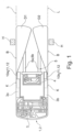
- an industrial truck 1 according to the invention is shown in a plan view.
- the industrial truck 1 is designed as a reach truck 2 in the exemplary embodiments shown.
- Identical components are provided with the same reference numbers in the figures.
- the reach truck 2 has a vehicle body 3 which has two wheel arms 3a, 3b which are arranged parallel to one another and extend in the longitudinal direction of the vehicle. Between the wheel arms 3a, 3b designed as a push mast lifting mast 4 is arranged to be displaceable in the longitudinal direction of the vehicle. On the lifting mast 4, a lifting device 5 is arranged such that it can be raised and lowered and is designed, for example, as a load fork with two forks 6a, 6b.
- a roller is arranged at the front ends of the wheel arms 3a, 3b, with which the industrial truck 1 is supported on a roadway.
- a sensor device 10a, 10b for monitoring a surrounding area is provided on each of the wheel arms 3a, 3b. If the sensor device 10a, 10b detects an obstacle in the surrounding area, a warning signal is generated and/or an intervention is made in the traction drive of the industrial truck 1, For example, the industrial truck brakes to avoid colliding with the obstacle.
- the sensor devices 10a, 10b have corresponding detection areas D1, D2, which form the monitoring areas that are monitored for obstacles. If an obstacle is detected in the detection area D1, D2, a warning signal is generated and/or an intervention in the traction drive of the industrial truck 1 is carried out.
- the detection areas D1, D2 are aligned with the area in front of the wheel arms 3a, 3b or in front of the load handling device 5 when the industrial truck 1 is driving in the direction of travel with the load handling device 5 in front.
- the sensor device 10a, 10b in the Figures 1 to 4 designed or arranged on the industrial truck 1 in such a way that there is an obstacle H, for example a shelf support of a shelf or a parked pallet, which is outside of a line L that is aligned with the vehicle outer contour K of the industrial truck 1 and the vehicle outer contour (vehicle outer edge) K in Direction of travel of the industrial truck 1 extended, outside of the detection area D1 or D2 of the sensor device 10a, 10b, in which a warning signal is generated and/or an intervention in the traction drive of the industrial truck is carried out.
- an obstacle H for example a shelf support of a shelf or a parked pallet, which is outside of a line L that is aligned with the vehicle outer contour K of the industrial truck 1 and the vehicle outer contour (vehicle outer edge) K in Direction of travel of the industrial truck 1 extended, outside of the detection area D1 or D2 of the sensor device 10a, 10b, in which a warning signal is generated and/or an intervention in the
- the sensor device 10a, 10b is this in the Figures 1 to 4 designed or arranged on the industrial truck 1 in such a way that the detection area D1, D2 of the sensor device 10a, 10b has an outer boundary edge B on or within the line L, which is aligned with the outer vehicle contour K of the industrial truck 1 and the outer vehicle contour K in the direction of travel of the industrial truck 1 extended.
- the outer boundary edge B of the detection area D1, D2 is arranged in a line with the vehicle outer contour K of the industrial truck 1 or its extension in the direction of travel.
- the sensor devices 10a, 10b each have a single detection area D1, D2.
- the sensor devices 10a, 10b are designed, for example, as an ultrasonic sensor 11 or as a radar sensor 12 or as an inductive sensor.
- the sensor devices 10a, 10b are designed as a single-beam laser sensor 13.
- the sensor devices 10a, 10b are arranged adjustably on the industrial truck 1, for example by means of an adapter not shown in detail, in order to achieve the inventive alignment of the detection areas D1, D2 by appropriate arrangement and alignment of the sensor devices 10a, 10b, according to which the outer boundary edge B of the respective single Detection area D1, D2 is in a line with the vehicle outer contour K of the truck 1 or its extension in the direction of travel.
- a sensor device 10b designed as an ultrasonic sensor 12 is arranged on the wheel arm 3b, in which the detection area D2 is designed in the form of a sound lobe.
- the sensor device 10b designed as an ultrasonic sensor 12 is arranged adjustably on the industrial truck 1, for example by means of an adapter not shown in detail, in order to achieve the inventive alignment of the detection area D2 by appropriate arrangement and alignment of the ultrasonic sensor 12, according to which the sound cone is parallel to the line L, which extends the vehicle outer contour K in the direction of travel and thus the outer boundary edge B of the detection area D1, D2 is in a line with the vehicle outer contour K of the industrial truck 1 or its extension in the direction of travel.
- the single-beam laser sensor 13 arranged on the wheel arm 3a is arranged on the industrial truck 1 in such a way that the laser beam forming the outer boundary edge B of the detection area D1 is aligned along the vehicle outer contour K and its extension in the direction of travel.
- the emitted laser beam is thus on the line L, which is aligned with the vehicle's outer contour K and extends it in the direction of travel.
- the single-beam laser sensor 13 is arranged on the outer contour K of the vehicle.
- a deflection mirror 15 is provided for the single-beam laser sensor 13 arranged on the wheel arm 3b, which deflects the emitted laser beam in such a way that the laser beam forming the outer boundary edge B of the detection area D1 is aligned along the vehicle outer contour K and its extension in the direction of travel, so that the emitted laser beam is on the line L, which is aligned with the vehicle's outer contour K and extends it in the direction of travel.
- the deflection mirror 15 allows the single-beam laser sensor 13 to be arranged further inside on the industrial truck 1 and is therefore more protected.
- an industrial truck 1 in which a sensor device 10a is arranged on the wheel arm 3a, which can monitor several areas B1-B5 in the detection area D1.
- the sensor device 10a of figure 4 is designed, for example, as a lidar sensor or time-of-flight camera 16 or stereo camera.
- Such sensor devices supply a large number of pixels in the detection area D1, so that a number of areas B1-B5 can be distinguished within the detection area D1.
- This sensor device 10a is designed such that the sensor device 10a only evaluates those areas B3, B4, B5 for monitoring an obstacle that are within the vehicle contour K or its extension in the direction of travel (line L).
- the areas B1, B2 of the detection area D1 which protrude beyond a certain distance from the vehicle contour K or its extension in the direction of travel, are only taken into account by the software for monitoring up to this distance.
- the areas B1, B2 extending from the vehicle outer contour K or its extension in the direction of travel and thus beyond the line L can be switched off for this purpose and thus excluded from the monitoring.
- a warning signal and/or an intervention in the traction drive of the industrial truck 1 therefore only occurs if an obstacle is detected in the areas B3, B4, B5, which form the monitored detection area D1.
- the areas B1, B2 protruding from the vehicle outer contour K can also be switched off as a function of the steering angle of the industrial truck 1, so that cornering of the industrial truck can be taken into account.
- an industrial truck 1 that is operated by a driver and that is provided with an assistance system that generates a warning signal when an obstacle is detected in the detection area D1, D2 of the sensor device 10a, 10b and/or intervenes in the traction drive of the industrial truck 1 of the invention, according to which no warning signal is generated when driving close to an obstacle H and/or no intervention is made in the traction drive of the industrial truck 1, acceptance by the driver is increased.
- the invention is not limited to the illustrated embodiment of an industrial truck 1 as a reach truck, but can also be used in other embodiments of industrial trucks 1, for example in a counterbalanced forklift.
- the invention can also be used not only for one direction of travel with the load handling device 5 in front, but also for the opposite or both directions of travel of the industrial truck 1.
- a signal from an ultrasonic sensor 11 can also be deflected and an ultrasonic sensor can be arranged further inside and thus more protected.
Landscapes
- Engineering & Computer Science (AREA)
- Structural Engineering (AREA)
- Automation & Control Theory (AREA)
- Remote Sensing (AREA)
- Physics & Mathematics (AREA)
- General Physics & Mathematics (AREA)
- Radar, Positioning & Navigation (AREA)
- Life Sciences & Earth Sciences (AREA)
- Geology (AREA)
- Mechanical Engineering (AREA)
- Aviation & Aerospace Engineering (AREA)
- Transportation (AREA)
- Civil Engineering (AREA)
- Optical Radar Systems And Details Thereof (AREA)
- Forklifts And Lifting Vehicles (AREA)
Description
- Die Erfindung betrifft ein Flurförderzeug mit einer Sensoreinrichtung zur Überwachung eines Umgebungsbereiches, wobei bei einem von der Sensoreinrichtung in dem Umgebungsbereich erfassten Hindernis ein Warnsignal erzeugt und/oder ein Eingriff in den Fahrantrieb des Flurförderzeugs durchgeführt wird, wobei die Sensoreinrichtung einen Detektionsbereich aufweist, der auf den Bereich vor einem Lastaufnahmemittel ausgerichtet ist, wenn das Flurförderzeug in Fahrtrichtung mit dem Lastaufnahmemittel voraus fährt.
- Flurförderzeuge, die von einem Fahrer bedient sein können oder fahrerlos (autonom) betrieben sein können, sind mit einer als Umgebungssensor ausgebildeten Sensoreinrichtung versehen, die den im Fahrweg liegenden Umgebungsbereich und somit das Umfeld des Flurförderzeugs auf Hindernisse überwacht, um Kollisionen des Flurförderzeugs mit einem Hindernis zu vermeiden. Dies trifft insbesondere auf in Lagerbereichen betriebene Flurförderzeuge zu. Häufige Ausführungsformen derartiger Flurförderzeuge sind Schubmaststapler, Gegengewichtsgabelstapler oder Regalbediengeräte. Zur Erfassung und Überwachung des Umgebungsbereiches werden an derartigen Flurförderzeugen Sensoreinrichtungen eingesetzt, die laufzeitmessende Systeme sind, wie Ultraschall-, Radar- oder Lasersensoren, beispielsweise Laserscanner. Ebenso sind auch Bildverarbeitungssysteme bekannt, die aus einem Kamerabild oder einem Stereokamerabild die Umgebung erfassen, beispielsweise mittels einer Time-of-Flight-Kamera. Auch ist es bekannt, als Sensoreinrichtungen zur Überwachung des Umgebungsbereichs des Flurförderzeugs induktive Sensoren zu verwenden.
- Mit der an dem Flurförderzeug angeordneten Sensoreinrichtung werden Hindernisse im Fahrweg des Flurförderzeugs erkannt, und im Falle eines erkannten Hindernisses in dem Fahrweg ein Warnsignal ausgegeben und/oder durch einen Eingriff in den Fahrantrieb des Flurförderzeugs das Flurförderzeug angehalten, um eine Kollision mit dem Hindernis zu vermeiden. Derartige Sensoreinrichtungen können bei fahrerlos betriebenen, sogenannten autonom fahrenden Flurförderzeugen eingesetzt werden oder auch als Assistenzsysteme bei Flurförderzeugen, die von einem Fahrer bedient werden.
- Bei Schubmaststaplern, bei denen der Hubmast zwischen zwei Radarmen angeordnet ist, werden derartige Sensoreinrichtungen an den Radarmen verwendet, um das Anfahren des Schubmaststaplers mit den Radarmen an Hindernisse, beispielsweise Regalstützen eines Regals, zu vermeiden, wenn der Schubmaststapler zur Aufnahme oder zum Absetzen einer Last in Fahrtrichtung mit den Radarmen voraus gefahren wird. Die Sensoreinrichtungen sind an derartigen Schubmaststaplern an den Radarmen angeordnet und parallel zu den Gabelzinken eines als Lastgabel ausgebildeten Lastaufnahmemittels ausgerichtet, so dass die Sensoreinrichtungen seitlich an dem Lastaufnahmemittel vorbei nach vorne orientiert die Umgebung vor dem Lastaufnahmemittel bzw. vor den Radarmen erfassen.
- Bekannte Sensoreinrichtungen weisen einen Detektionsbereich auf, der seitlich über die Fahrzeugaußenkontur bzw. seitlich über die Verlängerung der Fahrzeugaußenkontur in Fahrtrichtung hinausragt. Sofern sich hierbei ein Hindernis nahe und somit mit geringem seitlichem Abstand neben dem Flurförderzeug befindet und somit das Flurförderzeugs mit geringem seitlichen Abstand an einem Hindernis vorbeifährt, kommt es zu Fehldetektionen, bei denen das seitlich neben dem Flurförderzeug befindliche Hindernis erkannt wird und ein Warnsignal erzeugt wird und/oder ein Eingriff in den Fahrantrieb des Flurförderzeugs erfolgt, beispielweise das Flurförderzeug abgebremst wird. Derartige Betriebssituationen, in denen Fehldetektionen durch ein Nahe-Vorbei-Fahren an einem Hindernis auftreten, sind das Einstapeln von Lasten in ein Regal, beispielsweise mittels eines Schubmaststaplers, wobei die seitlichen Abstände zu Regalstützen des Regals sehr gering sind und die Regalstützen als Hindernisse von der Sensoreinrichtung erkannt werden. Auch können derartige Betriebssituationen, in denen Fehldetektionen durch ein Nahe-Vorbei-Fahren an einem Hindernis auftreten, eine Einfahrt eines Flurförderzeugs in ein Drive-In-Regal, wobei die seitlichen Abstände zu Regalstützen des Regals sehr gering sind und die Regalstützen als Hindernisse von der Sensoreinrichtung erkannt werden, oder eine Einfahrt eines Flurförderzeugs in ein Blocklager sein, wobei die seitlichen Abstände zu abgestellten Paletten sehr gering sind und die abgestellten Paletten als Hindernisse von der Sensoreinrichtung erkannt werden. Fehldetektionen in derartigen Betriebssituationen erfolgen bei Sensoreinrichtungen, die den Bereich vor dem Lastaufnahmemittel des Flurförderzeugs bzw. vor den Radarmen eines als Schubmaststaplers ausgebildeten Flurförderzeugs überwachen, wenn das Flurförderzeug in Fahrtrichtung mit dem Lastaufnahmemittel voraus fährt.
- Sofern das Flurförderzeug von einem Fahrer bedient wird und ein Assistenzsystem vorgesehen ist, das bei einem im Detektionsbereich der Sensoreinrichtung, der den Überwachungsbereich bildet, erkannten Hindernis ein Warnsignal erzeugt und/oder einen Eingriff in den Fahrantrieb des Flurförderzeugs durchgeführt, ist es für die Akzeptanz des Assistenzsystems durch den Fahrer sehr störend, wenn in Betriebssituationen, in denen das Flurförderzeugs mit geringem seitlichen Abstand an einem Hindernis, beispielsweise an einer Regalstütze und/oder an einer abgestellten Palette, vorbeifährt, die Sensoreinrichtung ein Hindernis detektiert und ein Warnsignal erzeugt wird und/oder ein Eingriff in den Fahrantrieb des Flurförderzeugs durchgeführt wird, beispielsweise eine Reduzierung der Fahrgeschwindigkeit auf Schleichfahrt erfolgt.
- Aus der
DE 10 2008 008 922 A1 ist ein Schubmaststapler bekannt, der einen Überwachungssensor zur Erfassung von Hindernissen und Vermeidung von Kollisionen am vorderen Ende eines Radarms aufweist. - Aus der
EP 0 800 129 B1 ist ein Flurförderzeug mit Mitteln zur Erfassung der Position und Ausrichtung eines Transportgutes sowie zur Erfassung von Hindernissen bekannt, wobei das Flurförderzeug Mittel zum Abbremsen des Flurförderzeugs im Fall der Erkennung von Hindernissen aufweist. - Die
GB 2 157 436 A - Die
JP S63 27398 A - Die
JP 2015 170248 A JP 2015 170284 A - Der vorliegenden Erfindung liegt die Aufgabe zugrunde, ein Flurförderzeug der eingangs genannten Gattung zur Verfügung zu stellen, bei dem Fehldetektionen infolge eines Nahe-Vorbei-Fahrens des Flurförderzeugs mit geringem seitlichen Abstand an einem Hindernis und damit verbundene Warnsignale und/oder Eingriffe in den Fahrantrieb des Flurförderzeugs vermieden werden.
- Diese Aufgabe wird erfindungsgemäß dadurch gelöst, dass die Sensoreinrichtung derart ausgeführt oder derart am Flurförderzeug angeordnet ist, dass sich ein Hindernis, das sich außerhalb einer Linie befindet, die mit der Fahrzeugaußenkontur des Flurförderzeugs fluchtet und die Fahrzeugaußenkontur in Fahrtrichtung des Flurförderzeugs verlängert, außerhalb des Detektionsbereichs der Sensoreinrichtung befindet, in dem ein Warnsignal erzeugt und/oder ein Eingriff in den Fahrantrieb des Flurförderzeugs durchgeführt wird. Erfindungsgemäß ist die Sensoreinrichtung derart ausgeführt oder derart am Flurförderzeug angeordnet, dass sich ein Hindernis, das außerhalb der Fahrzeugaußenkontur des Flurförderzeugs und der Verlängerung der Fahrzeugaußenkontur in Fahrtrichtung angeordnet ist, sich nicht mehr im Detektionsbereichs der Sensoreinrichtung befindet, in dem ein Warnsignal erzeugt und/oder ein Eingriff in den Fahrantrieb des Flurförderzeugs bewirkt wird. Eine derartige Ausführung bzw. Anordnung der Sensoreinrichtung ermöglicht es auf einfache Weise, dass Fehldetektionen vermieden werden, wenn ein Nahe-Vorbei-Fahren des Flurförderzeugs mit geringem seitlichen Abstand an einem Hindernis erfolgt. Mit dem erfindungsgemäßen Flurförderzeug kann somit ein Nahe-Vorbei-Fahren des Flurförderzeugs mit geringem seitlichen Abstand an einem Hindernis erfolgen, ohne dass die Sensoreinrichtung ein Hindernis erkennt und somit kein entsprechendes Warnsignal erzeugt wird und/oder kein Eingriff in den Fahrantrieb des Flurförderzeugs erfolgt.
- Gemäß einer vorteilhaften Ausgestaltungsform der Erfindung ist die Sensoreinrichtung derart ausgeführt oder derart am Flurförderzeug angeordnet, dass der Detektionsbereich der Sensoreinrichtung mit einer äußeren Begrenzungskante auf oder innerhalb der Linie ist, die mit der Fahrzeugaußenkontur des Flurförderzeugs fluchtet und die Fahrzeugaußenkontur in Fahrtrichtung des Flurförderzeugs verlängert. Die äußere Begrenzungskante des Detektionsbereichs der Sensoreinrichtung ragt somit nicht über die Fahrzeugaußenkontur und deren Verlängerung in Fahrtrichtung hinaus, wodurch auf einfache Weise erzielt wird, dass beim Nahe-Vorbei-Fahren des Flurförderzeugs mit geringem seitlichen Abstand an einem Hindernis kein entsprechendes Warnsignal erzeugt wird und/oder kein Eingriff in den Fahrantrieb des Flurförderzeugs erfolgt.
- Bevorzugt ist gemäß einer vorteilhaften Ausgestaltungsform der Erfindung die äußere Begrenzungskante des Detektionsbereichs in einer Linie mit der Fahrzeugaußenkontur des Flurförderzeugs angeordnet. Die äußere Begrenzungskante des Detektionsbereichs der Sensoreinrichtung befindet sich somit in einer Linie mit der Fahrzeugaußenkontur und deren Verlängerung in Fahrtrichtung hinaus.
- Bevorzugt ist gemäß einer alternativen und ebenfalls vorteilhaften Ausgestaltungsform der Erfindung der Detektionsbereich parallel zu der die Fahrzeugaußenkontur in Fahrtrichtung des Flurförderzeugs verlängernden Linie ausgerichtet. Der Detektionsbereich der Sensoreinrichtung ist somit mit parallel zur Verlängerung der Fahrzeugaußenkontur in Fahrtrichtung hinaus ausgerichtet. Hierdurch kann bei einem keulenförmigen Detektionsbereich auf einfache Weise erzielt werden, dass der keulenförmige Detektionsbereich parallel zur Fahrzeugaußenkontur ausgerichtet ist und die äußere Begrenzungskante des Detektionsbereiches nicht über die Verlängerung der Fahrzeugaußenkontur hinausragt.
- Gemäß einer vorteilhaften Ausgestaltungsform der Erfindung weist die Sensoreinrichtung einen einzigen Detektionsbereich auf. Bei einer Sensoreinrichtung, die einen einzigen Detektionsbereich aufweist, kann durch eine entsprechende Anordnung und somit Ausrichtung der Sensoreinrichtung am Flurförderzeug auf einfache Weise erzielt werden, dass der Detektionsbereich der Sensoreinrichtung mit der äußeren Begrenzungskante auf oder innerhalb der Linie ist, die mit der Fahrzeugaußenkontur des Flurförderzeugs fluchtet und die Fahrzeugaußenkontur in Fahrtrichtung des Flurförderzeugs verlängert.
- Derartige Sensoreinrichtungen können als Ultraschallsensor oder als Radarsensor oder als induktiver Sensor oder als Laserstrahlsensor, insbesondere Ein-Strahl-Lasersensor, ausgebildet sein.
- Eine entsprechende Anordnung und Ausrichtung einer derartigen Sensoreinrichtung kann auf einfache Weise erzielt werden, wenn gemäß einer vorteilhaften Ausgestaltungsform der Erfindung die Sensoreinrichtung mittels eines Adapters einstellbar am Flurförderzeug angeordnet ist. Durch entsprechende Verstellung der Sensoreinrichtung mittels des Adapters kann auf einfache und schnelle Weise die Sensoreinrichtung derart ausgerichtet werden, dass der Detektionsbereich der Sensoreinrichtung mit einer äußeren Begrenzungskante auf oder innerhalb der Linie ist, die mit der Fahrzeugaußenkontur des Flurförderzeugs fluchtet und die Fahrzeugaußenkontur in Fahrtrichtung des Flurförderzeugs verlängert.
- Gemäß einer alternativen Ausführungsform der Erfindung ist ein Umlenkspiegel vorgesehen, der den Detektionsbereich der Sensoreinrichtung auf oder innerhalb der in Fahrtrichtung des Flurförderzeugs verlängerten Fahrzeugaußenkontur des Flurförderzeugs hält. Mit einem Umlenkspiegel kann insbesondere bei der Ausbildung der Sensoreinrichtung als Ein-Strahl-Lasersensor der Laserstrahl und somit die äußere Begrenzungskante des Detektionsbereichs auf oder innerhalb der Linie gehalten werden, die mit der Fahrzeugaußenkontur des Flurförderzeugs fluchtet und die Fahrzeugaußenkontur in Fahrtrichtung des Flurförderzeugs verlängert.
- Gemäß einer alternativen Ausführungsform der Erfindung überwacht die Sensoreinrichtung in dem Detektionsbereich mehrere Bereiche. Bei einer Sensoreinrichtung, die mehrere Bereiche innerhalb des Detektionsbereichs überwacht und somit mehrere Bereiche innerhalb des Detektionsbereichs unterscheidet, können vorteilhafterweise nur diejenigen Bereiche ausgewertet werden, die innerhalb der Fahrzeugaußenkontur und deren Verlängerung in Fahrtrichtung liegen, um Fehldetektionen beim Nahe-Vorbei-Fahren des Flurförderzeugs mit geringem seitlichen Abstand an einem Hindernis zu verhindern.
- Hierzu werden gemäß einer vorteilhaften Ausführungsform der Erfindung diejenigen Bereiche abgeschaltet, die sich außerhalb der Linie befinden, die mit der Fahrzeugaußenkontur des Flurförderzeugs fluchtet und die Fahrzeugaußenkontur in Fahrtrichtung des Flurförderzeugs verlängert. Das Abschalten kann beispielsweise softwaretechnisch erfolgen, in dem bestimmte Bereiche des Detektionsbereichs, die bei einer bestimmten Entfernung aus der Fahrzeugkontur bzw. deren Verlängerung in Fahrtrichtung hinausgehen, softwaretechnisch nur bis zu dieser Entfernung berücksichtigt werden.
- Gemäß einer vorteilhaften Weiterbildung der Erfindung erfolgt die Abschaltung der Bereiche in Abhängigkeit von dem Lenkwinkel des Flurförderzeugs. Dadurch kann auf einfache Weise eine Kurvenfahrt berücksichtigt werden. Hierzu kann beispielsweise eine Trajektorie berechnet werden und die Überwachung der Bereiche außerhalb dieser Trajektorie ausgeschlossen werden.
- Eine derartige Sensoreinrichtung kann als Lidar (Light detection and ranging)-Sensor oder Time-of-Flight-Kamera oder Stereokamera ausgebildet sein. Derartige Sensoreinrichtungen weisen im Überwachungsbereich viele Bildpunkte auf, so dass mehrere Bereiche innerhalb des Detektionsbereichs unterschieden werden können und somit diejenigen Bereich von der Überwachung abgeschaltet und somit ausgeschlossen werden können, die aus der Fahrzeugaußenkontur und deren Verlängerung in Fahrtrichtung herausragen.
- Weitere Vorteile und Einzelheiten der Erfindung werden anhand der in den schematischen Figuren dargestellten Ausführungsbeispiele näher erläutert. Hierbei zeigt
- Figur 1
- eine erste Ausführungsform eines erfindungsgemäßen Flurförderzeug,
- Figur 2
- eine zweite Ausführungsform eines erfindungsgemäßen Flurförderzeug,
- Figur 3
- zwei weitere Ausführungsformen eines erfindungsgemäßen Flurförderzeugs und
- Figur 4
- eine weitere Ausführungsformen eines erfindungsgemäßen Flurförderzeugs.
- In den
Figuren 1 bis 4 ist jeweils ein erfindungsgemäßes Flurförderzeug 1 in einer Draufsicht dargestellt. Das Flurförderzeug 1 ist in den dargestellten Ausführungsbeispielen als Schubmaststapler 2 ausgebildet. Gleiche Bauteile sind in den Figuren mit gleichen Bezugsziffern versehen. - Der Schubmaststapler 2 weist einen Fahrzeugkörper 3 auf, der zwei parallel zueinander angeordnete Radarme 3a, 3b aufweist, die sich in Fahrzeuglängsrichtung erstrecken. Zwischen den Radarmen 3a, 3b ist ein als Schubmast ausgebildeter Hubmast 4 in Fahrzeuglängsrichtung verschiebbar angeordnet. An dem Hubmast 4 ist ein Lastaufnahmemittel 5 anhebbar und absenkbar angeordnet, das beispielsweise als Lastgabel mit zwei Gabelzinken 6a, 6b ausgeführt ist.
- An den vorderen Enden der Radarme 3a, 3b ist jeweils eine Laufrolle angeordnet, mit denen sich das Flurförderzeug 1 auf einer Fahrbahn abstützt.
- An den Radarmen 3a, 3b ist jeweils eine Sensoreinrichtung 10a, 10b zur Überwachung eines Umgebungsbereiches vorgesehen. Bei einem von der Sensoreinrichtung 10a, 10b in dem Umgebungsbereich erfassten Hindernis wird ein Warnsignal erzeugt und/oder ein Eingriff in den Fahrantrieb des Flurförderzeugs 1 durchgeführt, beispielsweise das Flurförderzeug abgebremst, um eine Kollision mit dem Hindernis zu vermeiden. Die Sensoreinrichtungen 10a, 10b weisen hierzu entsprechende Detektionsbereiche D1, D2 auf, die die Überwachungsbereiche bilden, die auf Hindernisse überwacht werden. Sofern in dem Detektionsbereich D1, D2 ein Hindernis erfasst wird, wird ein Warnsignal erzeugt und/oder ein Eingriff in den Fahrantrieb des Flurförderzeugs 1 durchgeführt. Die Detektionsbereich D1, D2 sind auf den Bereich vor die Radarme 3a, 3b bzw. vor das Lastaufnahmemittel 5 ausgerichtet, wenn das Flurförderzeug 1 in Fahrtrichtung mit dem Lastaufnahmemittel 5 voraus fährt.
- Erfindungsgemäß ist die Sensoreinrichtung 10a, 10b in den
Figuren 1 bis 4 derart ausgeführt oder derart am Flurförderzeug 1 angeordnet, dass sich ein Hindernis H, beispielsweise eine Regalstütze eines Regals oder eine abgestellte Palette, das sich außerhalb einer Linie L befindet, die mit der Fahrzeugaußenkontur K des Flurförderzeugs 1 fluchtet und die Fahrzeugaußenkontur (Fahrzeugaußenkante) K in Fahrtrichtung des Flurförderzeugs 1 verlängert, außerhalb des Detektionsbereichs D1 bzw. D2 der Sensoreinrichtung 10a, 10b befindet, in dem ein Warnsignal erzeugt und/oder ein Eingriff in den Fahrantrieb des Flurförderzeugs durchgeführt wird. - Die Sensoreinrichtung 10a, 10b ist hierzu in den
Figuren 1 bis 4 derart ausgeführt oder derart am Flurförderzeug 1 angeordnet, dass der Detektionsbereich D1, D2 der Sensoreinrichtung 10a, 10b mit einer äußeren Begrenzungskante B auf oder innerhalb der Linie L ist, die mit der Fahrzeugaußenkontur K des Flurförderzeugs 1 fluchtet und die Fahrzeugaußenkontur K in Fahrtrichtung des Flurförderzeugs 1 verlängert. - In den
Figuren 1 bis 3 ist die äußere Begrenzungskante B des Detektionsbereichs D1, D2 in einer Linie mit der Fahrzeugaußenkontur K des Flurförderzeugs 1 bzw. deren Verlängerung in Fahrtrichtung angeordnet. - In den
Figuren 1 bis 3 weisen die Sensoreinrichtungen 10a, 10b jeweils einen einzigen Detektionsbereich D1, D2 auf. - In der
Figur 1 und2 sind die Sensoreinrichtungen 10a, 10b beispielsweise als Ultraschallsensor 11 oder als Radarsensor 12 oder als induktiver Sensor ausgebildet. In derFigur 3 sind die Sensoreinrichtungen 10a, 10b als Ein-Strahl-Lasersensor 13 ausgebildet. - In der
Figur 1 sind die Sensoreinrichtungen 10a, 10b beispielsweise mittels eines nicht näher dargestellten Adapters einstellbar am Flurförderzeug 1 angeordnet, um durch entsprechende Anordnung und Ausrichtung der Sensoreinrichtungen 10a, 10b die erfindungsgemäße Ausrichtung der Detektionsbereiche D1, D2 zu erzielen, gemäß der die äußere Begrenzungskante B des jeweils einzigen Detektionsbereichs D1, D2 in einer Linie mit der Fahrzeugaußenkontur K des Flurförderzeugs 1 bzw. deren Verlängerung in Fahrtrichtung ist. - In der
Figur 2 ist an dem Radarm 3b eine als Ultraschallsensor 12 ausgebildete Sensoreinrichtung 10b angeordnet, bei dem der Detektionsbereich D2 in Form einer Schallkeule ausgebildet ist. In derFigur 2 ist die als Ultraschallsensor 12 ausgebildete Sensoreinrichtung 10b beispielsweise mittels eines nicht näher dargestellten Adapters einstellbar am Flurförderzeug 1 angeordnet, um durch entsprechende Anordnung und Ausrichtung des Ultraschallsensors 12 die erfindungsgemäße Ausrichtung des Detektionsbereichs D2 zu erzielen, gemäß der die Schallkeule parallel zu der Linie L ist, die die Fahrzeugaußenkontur K in Fahrtrichtung verlängert und somit die äußere Begrenzungskante B des Detektionsbereichs D1, D2 in einer Linie mit der Fahrzeugaußenkontur K des Flurförderzeugs 1 bzw. deren Verlängerung in Fahrtrichtung ist. - In der
Figur 3 ist der an dem Radarm 3a angeordnete Ein-Strahl-Lasersensor 13 derart an dem Flurförderzeug 1 angeordnet, dass der die äußere Begrenzungskante B des Detektionsbereichs D1 bildende Laserstrahl entlang der Fahrzeugaußenkontur K und deren Verlängerung in Fahrtrichtung ausgerichtet ist. Der ausgesandte Laserstrahl liegt somit auf der Linie L, die mit der Fahrzeugaußenkontur K fluchtet und diese in Fahrtrichtung verlängert. Der Ein-Strahl-Lasersensor 13 ist hierzu an der Fahrzeugaußenkontur K angeordnet. - In der
Figur 3 ist für den an dem Radarm 3b angeordneten Ein-Strahl-Lasersensor 13 ein Umlenkspiegel 15 vorgesehen, der den ausgesandten Laserstrahl derart umlenkt, dass der die äußere Begrenzungskante B des Detektionsbereichs D1 bildende Laserstrahl entlang der Fahrzeugaußenkontur K und deren Verlängerung in Fahrtrichtung ausgerichtet ist, so dass ausgesandte Laserstrahl auf der Linie L liegt, die mit der Fahrzeugaußenkontur K fluchtet und diese in Fahrtrichtung verlängert. Durch den Umlenkspiegel 15 kann der Ein-Strahl-Lasersensor 13 an dem Flurförderzeug 1 weiter innen und somit geschützter angeordnet werden. - In der
Figur 4 ist ein Flurförderzeug 1 dargestellt, bei dem an dem Radarm 3a eine Sensoreinrichtung 10a angeordnet, die in dem Detektionsbereich D1 mehrere Bereiche B1-B5 überwachen kann. Die Sensoreinrichtung 10a derFigur 4 ist beispielsweise als Lidar-Sensor oder Time-of-Flight-Kamera 16 oder Stereokamera ausgebildet. Derartige Sensoreinrichtungen liefern in dem Detektionsbereich D1 eine Vielzahl von Bildpunkten, so dass mehrere Bereiche B1-B5 innerhalb des Detektionsbereiches D1 unterschieden werden können. Diese Sensoreinrichtung 10a ist derart ausgeführt, dass von der Sensoreinrichtung 10a nur diejenigen Bereiche B3, B4, B5 für die Überwachung auf ein Hindernis ausgewertet werden, die sich innerhalb der Fahrzeugkontur K bzw. deren Verlängerung in Fahrtrichtung (Linie L) befinden. Die Bereiche B1, B2 des Detektionsbereichs D1, die ab einer bestimmten Entfernung aus der Fahrzeugkontur K bzw. deren Verlängerung in Fahrtrichtung hinaus ragen, werden software-technisch nur bis zu dieser Entfernung für die Überwachung berücksichtigt. Die aus der Fahrzeugaußenkontur K bzw. deren Verlängerung in Fahrtrichtung und somit über die Linie L hinausgehenden Bereiche B1, B2 können hierzu abgeschaltet und somit von der Überwachung ausgeschlossen werden. In derFigur 4 erfolgt somit nur dann ein Warnsignal und/oder ein Eingriff in den Fahrantrieb des Flurförderzeugs 1, wenn in den Bereichen B3, B4, B5, die den überwachten Detektionsbereich D1 bilden, ein Hindernis erkannt wird. - In der
Figur 4 kann das Abschalten der aus der Fahrzeugaußenkontur K hinausragenden Bereiche B1, B2 auch in Abhängigkeit von dem Lenkwinkel des Flurförderzeugs 1 erfolgen, so dass eine Kurvenfahrt des Flurförderzeugs berücksichtigt werden kann. - Wie aus den
Figuren 1 bis 4 ersichtlich ist, kann durch die erfindungsgemäße Anordnung der Sensoreinrichtung 10a, 10b in denFiguren 1 bis 3 bzw. die erfindungsgemäße Ausführung der Sensoreinrichtung 10a derFigur 4 erzielt werden, dass sofern das Flurförderzeug 1 an dem Hindernis H mit geringem seitlichen Abstand vorbeifährt, sich das Hindernis H nicht in dem Detektionsbereich D1 bzw. D2 der Sensoreinrichtung 10a, 10b befindet, in dem ein Warnsignal erzeugt und/oder ein Eingriff in den Fahrantrieb des Flurförderzeugs 1 durchgeführt wird. Von der Sensoreinrichtung 10a, 10b wird somit das Hindernis H nicht erkannt und es wird kein Warnsignal erzeugt und/oder kein Eingriff in den Fahrantrieb des Flurförderzeugs 1 durchgeführt. Hierdurch können Fehldetektionen beim Nahe-Vorbei-Fahren des Flurförderzeugs 1 an einem Hindernis H vermieden werden. - Bei einem Flurförderzeug 1, das von einem Fahrer bedient wird und ein Assistenzsystem vorgesehen ist, das bei einem im Detektionsbereich D1, D2 der Sensoreinrichtung 10a, 10b erkannten Hindernis ein Warnsignal erzeugt und/oder einen Eingriff in den Fahrantrieb des Flurförderzeugs 1 durchgeführt, kann mit der Erfindung, gemäß der bei einem Nahe-Vorbei-Fahren an einem Hindernis H kein Warnsignal erzeugt und/oder kein Eingriff in den Fahrantrieb des Flurförderzeugs 1 durchgeführt wird, die Akzeptanz bei dem Fahrer erhöht werden.
- Die Erfindung ist nicht auf das dargestellte Ausführungsbeispiel eines Flurförderzeugs 1 als Schubmaststapler beschränkt, sondern kann auch bei anderen Ausführungsformen von Flurförderzeugen 1 eingesetzt werden, beispielsweise bei einem Gegengewichtsgabelstapler. Die Erfindung kann zudem nicht nur für eine Fahrtrichtung mit dem Lastaufnahmemittel 5 voraus eingesetzt werden, sondern auch für die entgegengesetzte oder beide Fahrtrichtungen des Flurförderzeugs 1.
- Durch einen Umlenkspiegel 15 der
Figur 3 kann auch ein Signal eines Ultraschallsensors 11 umgelenkt werden und ein Ultraschallsensors weiter innen und somit geschützter angeordnet werden.
Claims (12)
- Flurförderzeug (1) mit einer Sensoreinrichtung (10a; 10b) zur Überwachung eines Umgebungsbereiches, wobei bei einem von der Sensoreinrichtung (10a; 10b) in dem Umgebungsbereich erfassten Hindernis (H) ein Warnsignal erzeugt und/oder ein Eingriff in den Fahrantrieb des Flurförderzeugs (1) durchgeführt wird, wobei die Sensoreinrichtung (10a; 10b) einen Detektionsbereich (D1; D2) aufweist, der auf den Bereich vor einem Lastaufnahmemittel (5) ausgerichtet ist, wenn das Flurförderzeug (1) in Fahrtrichtung mit dem Lastaufnahmemittel (5) voraus fährt, dadurch gekennzeichnet, dass die Sensoreinrichtung (10a; 10b) derart ausgeführt oder derart am Flurförderzeug (1) angeordnet ist, dass sich ein Hindernis (H), das sich außerhalb einer Linie (L) befindet, die mit der Fahrzeugaußenkontur (K) des Flurförderzeugs (1) fluchtet und die Fahrzeugaußenkontur (K) in Fahrtrichtung des Flurförderzeugs (1) verlängert, außerhalb des Detektionsbereichs (D1; D2) der Sensoreinrichtung (10a; 10b) befindet, in dem ein Warnsignal erzeugt und/oder ein Eingriff in den Fahrantrieb des Flurförderzeugs (1) durchgeführt wird.
- Flurförderzeug nach Anspruch 1, dadurch gekennzeichnet, dass die Sensoreinrichtung (10a; 10b) derart ausgeführt oder derart am Flurförderzeug (1) angeordnet ist, dass der Detektionsbereich (D1; D2) der Sensoreinrichtung (10a; 10b) mit einer äußeren Begrenzungskante (B) auf oder innerhalb der Linie (L) ist, die mit der Fahrzeugaußenkontur (K) des Flurförderzeugs (1) fluchtet und die Fahrzeugaußenkontur (K) in Fahrtrichtung des Flurförderzeugs (1) verlängert.
- Flurförderzeug nach Anspruch 1 oder 2, dadurch gekennzeichnet, dass die äußere Begrenzungskante (B) des Detektionsbereichs (D1; D2) in einer Linie (L) mit der Fahrzeugaußenkontur (K) des Flurförderzeugs (1) angeordnet ist.
- Flurförderzeug nach Anspruch 1 oder 2, dadurch gekennzeichnet, dass der Detektionsbereich (D1; D2) parallel zu der die Fahrzeugaußenkontur (K) in Fahrtrichtung des Flurförderzeugs (1) verlängernden Linie (L) ausgerichtet ist.
- Flurförderzeug nach einem der Ansprüche 1 bis 4, dadurch gekennzeichnet, dass die Sensoreinrichtung (10a; 10b) einen einzigen Detektionsbereich (D1; D2) aufweist.
- Flurförderzeug nach Anspruch 5, dadurch gekennzeichnet, dass die Sensoreinrichtung (10a; 10b) als Ultraschallsensor (11) oder als Radarsensor (12) oder als induktiver Sensor oder als Laserstrahlsensor, insbesondere Ein-Strahl-Lasersensor (13), ausgebildet ist.
- Flurförderzeug nach einem der Ansprüche 1 bis 6, dadurch gekennzeichnet, dass die Sensoreinrichtung (10a; 10b) mittels eines Adapters einstellbar am Flurförderzeug (1) angeordnet ist.
- Flurförderzeug nach einem der Ansprüche 1 bis 7, dadurch gekennzeichnet, dass ein Umlenkspiegel (15) vorgesehen ist, der den Detektionsbereich (D1; D2) der Sensoreinrichtung (10a; 10b) auf oder innerhalb der in Fahrtrichtung des Flurförderzeugs (1) verlängerten Fahrzeugaußenkontur (K) des Flurförderzeugs (1) hält.
- Flurförderzeug nach einem der Ansprüche 1 bis 4, dadurch gekennzeichnet, dass die Sensoreinrichtung (10a; 10b) in dem Detektionsbereich (D1) mehrere Bereiche (B1-B5) überwacht.
- Flurförderzeug nach Anspruch 9, dadurch gekennzeichnet, dass diejenigen Bereiche (B1, B2) abgeschaltet werden, die sich außerhalb der Linie (L) befinden, die mit der Fahrzeugaußenkontur (K) des Flurförderzeugs (1) fluchtet und die Fahrzeugaußenkontur (K) in Fahrtrichtung des Flurförderzeugs (1) verlängert.
- Flurförderzeug nach Anspruch 10, dadurch gekennzeichnet, dass die Abschaltung der Bereiche (B1, B2) in Abhängigkeit von dem Lenkwinkel des Flurförderzeugs (1) erfolgt.
- Flurförderzeug nach einem der Ansprüche 9 bis 11, dadurch gekennzeichnet, dass die Sensoreinrichtung (10a; 10b) als Lidar-Sensor oder Time-of-Flight-Kamera (16) oder Stereokamera ausgebildet ist.
Applications Claiming Priority (1)
| Application Number | Priority Date | Filing Date | Title |
|---|---|---|---|
| DE102016120117.0A DE102016120117A1 (de) | 2016-10-21 | 2016-10-21 | Flurförderzeug mit einer Sensoreinrichtung zur Überwachung eines Umgebungsbereiches |
Publications (2)
| Publication Number | Publication Date |
|---|---|
| EP3312131A1 EP3312131A1 (de) | 2018-04-25 |
| EP3312131B1 true EP3312131B1 (de) | 2023-07-12 |
Family
ID=59974341
Family Applications (1)
| Application Number | Title | Priority Date | Filing Date |
|---|---|---|---|
| EP17193765.9A Active EP3312131B1 (de) | 2016-10-21 | 2017-09-28 | Flurförderzeug mit einer sensoreinrichtung zur überwachung eines umgebungsbereiches |
Country Status (2)
| Country | Link |
|---|---|
| EP (1) | EP3312131B1 (de) |
| DE (1) | DE102016120117A1 (de) |
Families Citing this family (13)
| Publication number | Priority date | Publication date | Assignee | Title |
|---|---|---|---|---|
| EP3587894B1 (de) * | 2018-06-28 | 2023-08-09 | Leuze electronic GmbH + Co. KG | Sensoranordnung und verfahren zum betrieb einer sensoranordnung |
| DE102018117214A1 (de) * | 2018-07-17 | 2020-01-23 | Jungheinrich Aktiengesellschaft | Schubmaststapler mit einem Überwachungssensor sowie ein Verfahren zum Betrieb eines solchen |
| DE102018128406B4 (de) * | 2018-11-13 | 2023-05-11 | Jungheinrich Aktiengesellschaft | Flurförderzeug mit einem Notstoppsystem |
| DE102019213922A1 (de) * | 2019-09-12 | 2021-03-18 | Jungheinrich Aktiengesellschaft | Fahrzeug mit Umfeldüberwachungseinrichtung |
| KR102757112B1 (ko) | 2019-12-03 | 2025-01-21 | 가부시키가이샤 도요다 지도숏키 | 산업 차량 |
| CA3163133C (en) | 2020-02-21 | 2025-05-27 | Crown Equipment Corporation | Position assistance system for a materials handling vehicle |
| DE102020207479A1 (de) | 2020-06-17 | 2021-12-23 | Zf Friedrichshafen Ag | Gabelzinkensensoren zur Erkennung von Querverkehr |
| DE102020122204A1 (de) * | 2020-08-25 | 2022-03-03 | Jungheinrich Aktiengesellschaft | System mit einem Regalshuttlefahrzeug und einem Lagerregal |
| DE102021103799A1 (de) | 2021-02-18 | 2022-08-18 | Jungheinrich Aktiengesellschaft | Flurförderzeug mit erfassungseinrichtungen an gabelzinken |
| WO2023020940A1 (de) * | 2021-08-17 | 2023-02-23 | Schiller Automatisierungstechnik Gmbh | Verfahren zum betreiben eines fördermittels |
| DE102021004184A1 (de) * | 2021-08-17 | 2023-02-23 | Schiller Automatisierungstechnik Gmbh | Verfahren zum Betreiben eines Fördermittels |
| DE102021130254A1 (de) * | 2021-11-19 | 2023-05-25 | Jungheinrich Aktiengesellschaft | Verfahren zum handhaben von störungen in flurförderzeugen |
| CN115072316A (zh) * | 2022-08-01 | 2022-09-20 | 安徽行者智能科技股份有限公司 | 一种大尺寸复杂曲面智能加工系统用多功能转运模块 |
Citations (8)
| Publication number | Priority date | Publication date | Assignee | Title |
|---|---|---|---|---|
| US20040073359A1 (en) | 2002-01-23 | 2004-04-15 | Hisashi Ichijo | Position control device and position control method of stevedoring apparatus in industrial vehicle |
| GB2413449A (en) | 2004-02-12 | 2005-10-26 | Neil Sim | Vehicular based forward scanning device for collision avoidance |
| WO2008039649A2 (en) | 2006-09-14 | 2008-04-03 | Crown Equipment Corporation | Systems and methods of remotely controlling a materials handling vehicle |
| US20090114485A1 (en) | 2007-11-01 | 2009-05-07 | Eggert Richard T | Lift truck fork aligning system with operator indicators |
| US20110153139A1 (en) | 2009-12-17 | 2011-06-23 | Sick Ag | Optoelectronic sensor |
| DE102012104808A1 (de) | 2012-06-04 | 2013-12-05 | Still Gmbh | Flurförderzeug mit Positioniervorrichtung |
| US20140114526A1 (en) | 2012-10-22 | 2014-04-24 | Sick Ag | Safety apparatus for a vehicle |
| JP2015170284A (ja) | 2014-03-10 | 2015-09-28 | 株式会社日立製作所 | フォークリフト型無人搬送車、その制御方法および制御装置 |
Family Cites Families (6)
| Publication number | Priority date | Publication date | Assignee | Title |
|---|---|---|---|---|
| JPS5950379A (ja) * | 1982-09-16 | 1984-03-23 | Nippon Denso Co Ltd | 車両用障害物検出装置 |
| SE456372B (sv) * | 1984-04-06 | 1988-09-26 | Bt Ind Ab | Forfarande for att hos en operatorlos maskin detektera hinder |
| JPS6327398A (ja) * | 1986-07-22 | 1988-02-05 | 株式会社豊田自動織機製作所 | 無人フオ−クリフトの安全装置 |
| US4802096A (en) * | 1987-05-14 | 1989-01-31 | Bell & Howell Company | Controlled direction non-contact detection system for automatic guided vehicles |
| DE19613386A1 (de) | 1996-04-03 | 1997-10-09 | Fiat Om Carrelli Elevatori | Flurförderzeug, das wahlweise manuell oder automatisch betreibbar ausgebildet ist |
| DE102008008922B4 (de) | 2008-02-13 | 2023-07-06 | Still Gesellschaft Mit Beschränkter Haftung | Flurförderzeug mit Umgebungssensor |
-
2016
- 2016-10-21 DE DE102016120117.0A patent/DE102016120117A1/de active Pending
-
2017
- 2017-09-28 EP EP17193765.9A patent/EP3312131B1/de active Active
Patent Citations (8)
| Publication number | Priority date | Publication date | Assignee | Title |
|---|---|---|---|---|
| US20040073359A1 (en) | 2002-01-23 | 2004-04-15 | Hisashi Ichijo | Position control device and position control method of stevedoring apparatus in industrial vehicle |
| GB2413449A (en) | 2004-02-12 | 2005-10-26 | Neil Sim | Vehicular based forward scanning device for collision avoidance |
| WO2008039649A2 (en) | 2006-09-14 | 2008-04-03 | Crown Equipment Corporation | Systems and methods of remotely controlling a materials handling vehicle |
| US20090114485A1 (en) | 2007-11-01 | 2009-05-07 | Eggert Richard T | Lift truck fork aligning system with operator indicators |
| US20110153139A1 (en) | 2009-12-17 | 2011-06-23 | Sick Ag | Optoelectronic sensor |
| DE102012104808A1 (de) | 2012-06-04 | 2013-12-05 | Still Gmbh | Flurförderzeug mit Positioniervorrichtung |
| US20140114526A1 (en) | 2012-10-22 | 2014-04-24 | Sick Ag | Safety apparatus for a vehicle |
| JP2015170284A (ja) | 2014-03-10 | 2015-09-28 | 株式会社日立製作所 | フォークリフト型無人搬送車、その制御方法および制御装置 |
Non-Patent Citations (3)
| Title |
|---|
| ANONYMOUS: "Operator’s Manual BT RR B1-8, B1C-8C BT RR E1-8, E1C-8C Valid from serial number: 743537-", BT, 7 March 2005 (2005-03-07), XP093186975 |
| ANONYMOUS: "Photoelectric Sensors Series M18 - Technical Data", BERNSTEIN, 15 June 2021 (2021-06-15), XP093186973, Retrieved from the Internet <URL:https://pim.bernstein.eu/datenblaetter/6557217002%20en.pdf> |
| ANONYMOUS: "Safety Laser Scanner OS32C Series - User's Manual", OMRON, 1 January 2017 (2017-01-01), XP093186988 |
Also Published As
| Publication number | Publication date |
|---|---|
| DE102016120117A1 (de) | 2018-04-26 |
| EP3312131A1 (de) | 2018-04-25 |
Similar Documents
| Publication | Publication Date | Title |
|---|---|---|
| EP3312131B1 (de) | Flurförderzeug mit einer sensoreinrichtung zur überwachung eines umgebungsbereiches | |
| EP3583586B1 (de) | Automatisch geführtes transportfahrzeug für container und verfahren zum betreiben desselben sowie system mit einem automatisch geführten transportfahrzeug | |
| EP3241801B1 (de) | Verfahren zur kollisionsüberwachung bei einem flurförderzeug | |
| EP2692688B1 (de) | Fahrassistenzvorrichtung für ein Flurförderzeug sowie Flurförderzeug | |
| CA3187706C (en) | Materials handling vehicle obstacle scanning tools | |
| EP0800129B1 (de) | Flurförderzeug, das wahlweise manuell oder automatisch betreibbar ausgebildet ist | |
| DE102010028911A1 (de) | Verfahren und Vorrichtung zur Überwachung einer Bewegung eines Fahrzeugs | |
| DE102012106988B4 (de) | Verfahren zur Steuerung eines Flurförderzeugs | |
| EP4136049B1 (de) | Flurförderzeug mit lastaufnahmemitteln zur aufnahme von langgut | |
| EP2927768B2 (de) | Verfahren zum betreiben einer selbstbeweglichen mobilen plattform | |
| DE102011116822A1 (de) | Überwachungssystem zur Überwachung des Umfeldes von Fahrzeugen, insbesondere von Kraft- und/oder Nutzfahrzeugen | |
| EP3369696A1 (de) | Flurförderfahrzeug mit verbessertem sensorkonzept sowie flurfördersystem | |
| EP3800158A1 (de) | Flurförderzeug, eingerichtet für den fahrerlosen, autonom agierenden betrieb für eine zu transportierende last | |
| DE102020215149A1 (de) | Verfahren zum Betreiben eines Fahrzeugs in einem Regalgang in Abhängigkeit von einer Fahrweginformation | |
| EP4439218A1 (de) | Fahrerloses transportfahrzeug | |
| EP4296215B1 (de) | Autonom fahrendes transportsystem zum transport von paletten und/oder gitterboxen und verfahren zum betrieb eines solchen autonom fahrenden transportsystems | |
| EP3772483A1 (de) | Verfahren zur ermittlung der eigenbewegung eines flurförderzeugs | |
| DE102019215176A1 (de) | Flurförderzeug, eingerichtet für den fahrerlosen, autonom agierenden Betrieb für eine zu transportierende Last | |
| DE10221298A1 (de) | Flurförderzeug mit Abstands-Sensoren | |
| EP3216746B1 (de) | Flurförderzeug mit umgebungssensoren | |
| DE102019215169A1 (de) | Flurförderzeug, eingerichtet für den fahrerlosen, autonom agierenden Betrieb | |
| EP4464643A1 (de) | Verfahren zur hindernisbehandlung in einem flurförderzeug | |
| US12570509B2 (en) | Industrial truck with detection devices on the forks | |
| EP3178727B1 (de) | Verfahren zum erkennen einer längsparklücke zum parken eines kraftfahrzeugs anhand einer fahrbahnmarkierung, fahrerassistenzsystem sowie kraftfahrzeug | |
| EP4168348B1 (de) | Gabelzinkensensoren zur erkennung von querverkehr |
Legal Events
| Date | Code | Title | Description |
|---|---|---|---|
| PUAI | Public reference made under article 153(3) epc to a published international application that has entered the european phase |
Free format text: ORIGINAL CODE: 0009012 |
|
| STAA | Information on the status of an ep patent application or granted ep patent |
Free format text: STATUS: THE APPLICATION HAS BEEN PUBLISHED |
|
| AK | Designated contracting states |
Kind code of ref document: A1 Designated state(s): AL AT BE BG CH CY CZ DE DK EE ES FI FR GB GR HR HU IE IS IT LI LT LU LV MC MK MT NL NO PL PT RO RS SE SI SK SM TR |
|
| AX | Request for extension of the european patent |
Extension state: BA ME |
|
| STAA | Information on the status of an ep patent application or granted ep patent |
Free format text: STATUS: REQUEST FOR EXAMINATION WAS MADE |
|
| 17P | Request for examination filed |
Effective date: 20181018 |
|
| RBV | Designated contracting states (corrected) |
Designated state(s): AL AT BE BG CH CY CZ DE DK EE ES FI FR GB GR HR HU IE IS IT LI LT LU LV MC MK MT NL NO PL PT RO RS SE SI SK SM TR |
|
| STAA | Information on the status of an ep patent application or granted ep patent |
Free format text: STATUS: EXAMINATION IS IN PROGRESS |
|
| 17Q | First examination report despatched |
Effective date: 20200902 |
|
| REG | Reference to a national code |
Ref country code: DE Ref legal event code: R079 Free format text: PREVIOUS MAIN CLASS: B66F0017000000 Ipc: B66F0009075000 Ref document number: 502017015035 Country of ref document: DE |
|
| GRAP | Despatch of communication of intention to grant a patent |
Free format text: ORIGINAL CODE: EPIDOSNIGR1 |
|
| STAA | Information on the status of an ep patent application or granted ep patent |
Free format text: STATUS: GRANT OF PATENT IS INTENDED |
|
| RIC1 | Information provided on ipc code assigned before grant |
Ipc: B66F 17/00 20060101ALI20230220BHEP Ipc: B66F 9/075 20060101AFI20230220BHEP |
|
| INTG | Intention to grant announced |
Effective date: 20230329 |
|
| GRAS | Grant fee paid |
Free format text: ORIGINAL CODE: EPIDOSNIGR3 |
|
| GRAA | (expected) grant |
Free format text: ORIGINAL CODE: 0009210 |
|
| STAA | Information on the status of an ep patent application or granted ep patent |
Free format text: STATUS: THE PATENT HAS BEEN GRANTED |
|
| P01 | Opt-out of the competence of the unified patent court (upc) registered |
Effective date: 20230507 |
|
| AK | Designated contracting states |
Kind code of ref document: B1 Designated state(s): AL AT BE BG CH CY CZ DE DK EE ES FI FR GB GR HR HU IE IS IT LI LT LU LV MC MK MT NL NO PL PT RO RS SE SI SK SM TR |
|
| REG | Reference to a national code |
Ref country code: CH Ref legal event code: EP |
|
| REG | Reference to a national code |
Ref country code: DE Ref legal event code: R096 Ref document number: 502017015035 Country of ref document: DE |
|
| REG | Reference to a national code |
Ref country code: IE Ref legal event code: FG4D Free format text: LANGUAGE OF EP DOCUMENT: GERMAN |
|
| REG | Reference to a national code |
Ref country code: SE Ref legal event code: TRGR |
|
| REG | Reference to a national code |
Ref country code: LT Ref legal event code: MG9D |
|
| REG | Reference to a national code |
Ref country code: NL Ref legal event code: MP Effective date: 20230712 |
|
| PG25 | Lapsed in a contracting state [announced via postgrant information from national office to epo] |
Ref country code: NL Free format text: LAPSE BECAUSE OF FAILURE TO SUBMIT A TRANSLATION OF THE DESCRIPTION OR TO PAY THE FEE WITHIN THE PRESCRIBED TIME-LIMIT Effective date: 20230712 |
|
| PG25 | Lapsed in a contracting state [announced via postgrant information from national office to epo] |
Ref country code: GR Free format text: LAPSE BECAUSE OF FAILURE TO SUBMIT A TRANSLATION OF THE DESCRIPTION OR TO PAY THE FEE WITHIN THE PRESCRIBED TIME-LIMIT Effective date: 20231013 |
|
| PG25 | Lapsed in a contracting state [announced via postgrant information from national office to epo] |
Ref country code: ES Free format text: LAPSE BECAUSE OF FAILURE TO SUBMIT A TRANSLATION OF THE DESCRIPTION OR TO PAY THE FEE WITHIN THE PRESCRIBED TIME-LIMIT Effective date: 20230712 |
|
| PG25 | Lapsed in a contracting state [announced via postgrant information from national office to epo] |
Ref country code: IS Free format text: LAPSE BECAUSE OF FAILURE TO SUBMIT A TRANSLATION OF THE DESCRIPTION OR TO PAY THE FEE WITHIN THE PRESCRIBED TIME-LIMIT Effective date: 20231112 |
|
| PG25 | Lapsed in a contracting state [announced via postgrant information from national office to epo] |
Ref country code: RS Free format text: LAPSE BECAUSE OF FAILURE TO SUBMIT A TRANSLATION OF THE DESCRIPTION OR TO PAY THE FEE WITHIN THE PRESCRIBED TIME-LIMIT Effective date: 20230712 Ref country code: PT Free format text: LAPSE BECAUSE OF FAILURE TO SUBMIT A TRANSLATION OF THE DESCRIPTION OR TO PAY THE FEE WITHIN THE PRESCRIBED TIME-LIMIT Effective date: 20231113 Ref country code: NO Free format text: LAPSE BECAUSE OF FAILURE TO SUBMIT A TRANSLATION OF THE DESCRIPTION OR TO PAY THE FEE WITHIN THE PRESCRIBED TIME-LIMIT Effective date: 20231012 Ref country code: LV Free format text: LAPSE BECAUSE OF FAILURE TO SUBMIT A TRANSLATION OF THE DESCRIPTION OR TO PAY THE FEE WITHIN THE PRESCRIBED TIME-LIMIT Effective date: 20230712 Ref country code: LT Free format text: LAPSE BECAUSE OF FAILURE TO SUBMIT A TRANSLATION OF THE DESCRIPTION OR TO PAY THE FEE WITHIN THE PRESCRIBED TIME-LIMIT Effective date: 20230712 Ref country code: IS Free format text: LAPSE BECAUSE OF FAILURE TO SUBMIT A TRANSLATION OF THE DESCRIPTION OR TO PAY THE FEE WITHIN THE PRESCRIBED TIME-LIMIT Effective date: 20231112 Ref country code: HR Free format text: LAPSE BECAUSE OF FAILURE TO SUBMIT A TRANSLATION OF THE DESCRIPTION OR TO PAY THE FEE WITHIN THE PRESCRIBED TIME-LIMIT Effective date: 20230712 Ref country code: GR Free format text: LAPSE BECAUSE OF FAILURE TO SUBMIT A TRANSLATION OF THE DESCRIPTION OR TO PAY THE FEE WITHIN THE PRESCRIBED TIME-LIMIT Effective date: 20231013 Ref country code: FI Free format text: LAPSE BECAUSE OF FAILURE TO SUBMIT A TRANSLATION OF THE DESCRIPTION OR TO PAY THE FEE WITHIN THE PRESCRIBED TIME-LIMIT Effective date: 20230712 Ref country code: ES Free format text: LAPSE BECAUSE OF FAILURE TO SUBMIT A TRANSLATION OF THE DESCRIPTION OR TO PAY THE FEE WITHIN THE PRESCRIBED TIME-LIMIT Effective date: 20230712 |
|
| PG25 | Lapsed in a contracting state [announced via postgrant information from national office to epo] |
Ref country code: PL Free format text: LAPSE BECAUSE OF FAILURE TO SUBMIT A TRANSLATION OF THE DESCRIPTION OR TO PAY THE FEE WITHIN THE PRESCRIBED TIME-LIMIT Effective date: 20230712 |
|
| REG | Reference to a national code |
Ref country code: DE Ref legal event code: R026 Ref document number: 502017015035 Country of ref document: DE |
|
| PLBI | Opposition filed |
Free format text: ORIGINAL CODE: 0009260 |
|
| PLAX | Notice of opposition and request to file observation + time limit sent |
Free format text: ORIGINAL CODE: EPIDOSNOBS2 |
|
| PLAB | Opposition data, opponent's data or that of the opponent's representative modified |
Free format text: ORIGINAL CODE: 0009299OPPO |
|
| PG25 | Lapsed in a contracting state [announced via postgrant information from national office to epo] |
Ref country code: SM Free format text: LAPSE BECAUSE OF FAILURE TO SUBMIT A TRANSLATION OF THE DESCRIPTION OR TO PAY THE FEE WITHIN THE PRESCRIBED TIME-LIMIT Effective date: 20230712 Ref country code: RO Free format text: LAPSE BECAUSE OF FAILURE TO SUBMIT A TRANSLATION OF THE DESCRIPTION OR TO PAY THE FEE WITHIN THE PRESCRIBED TIME-LIMIT Effective date: 20230712 Ref country code: EE Free format text: LAPSE BECAUSE OF FAILURE TO SUBMIT A TRANSLATION OF THE DESCRIPTION OR TO PAY THE FEE WITHIN THE PRESCRIBED TIME-LIMIT Effective date: 20230712 Ref country code: DK Free format text: LAPSE BECAUSE OF FAILURE TO SUBMIT A TRANSLATION OF THE DESCRIPTION OR TO PAY THE FEE WITHIN THE PRESCRIBED TIME-LIMIT Effective date: 20230712 Ref country code: CZ Free format text: LAPSE BECAUSE OF FAILURE TO SUBMIT A TRANSLATION OF THE DESCRIPTION OR TO PAY THE FEE WITHIN THE PRESCRIBED TIME-LIMIT Effective date: 20230712 Ref country code: SK Free format text: LAPSE BECAUSE OF FAILURE TO SUBMIT A TRANSLATION OF THE DESCRIPTION OR TO PAY THE FEE WITHIN THE PRESCRIBED TIME-LIMIT Effective date: 20230712 |
|
| REG | Reference to a national code |
Ref country code: CH Ref legal event code: PL |
|
| PG25 | Lapsed in a contracting state [announced via postgrant information from national office to epo] |
Ref country code: LU Free format text: LAPSE BECAUSE OF NON-PAYMENT OF DUE FEES Effective date: 20230928 |
|
| 26 | Opposition filed |
Opponent name: TOYOTA MATERIAL HANDLING MANUFACTURING SWEDEN AB Effective date: 20240412 |
|
| REG | Reference to a national code |
Ref country code: BE Ref legal event code: MM Effective date: 20230930 |
|
| R26 | Opposition filed (corrected) |
Opponent name: TOYOTA MATERIAL HANDLING MANUFACTURING SWEDEN AB Effective date: 20240412 |
|
| PG25 | Lapsed in a contracting state [announced via postgrant information from national office to epo] |
Ref country code: LU Free format text: LAPSE BECAUSE OF NON-PAYMENT OF DUE FEES Effective date: 20230928 Ref country code: IT Free format text: LAPSE BECAUSE OF FAILURE TO SUBMIT A TRANSLATION OF THE DESCRIPTION OR TO PAY THE FEE WITHIN THE PRESCRIBED TIME-LIMIT Effective date: 20230712 Ref country code: MC Free format text: LAPSE BECAUSE OF FAILURE TO SUBMIT A TRANSLATION OF THE DESCRIPTION OR TO PAY THE FEE WITHIN THE PRESCRIBED TIME-LIMIT Effective date: 20230712 |
|
| PLAB | Opposition data, opponent's data or that of the opponent's representative modified |
Free format text: ORIGINAL CODE: 0009299OPPO |
|
| REG | Reference to a national code |
Ref country code: IE Ref legal event code: MM4A |
|
| PG25 | Lapsed in a contracting state [announced via postgrant information from national office to epo] |
Ref country code: IE Free format text: LAPSE BECAUSE OF NON-PAYMENT OF DUE FEES Effective date: 20230928 |
|
| R26 | Opposition filed (corrected) |
Opponent name: TOYOTA MATERIAL HANDLING MANUFACTURING SWEDEN AB Effective date: 20240412 |
|
| PG25 | Lapsed in a contracting state [announced via postgrant information from national office to epo] |
Ref country code: CH Free format text: LAPSE BECAUSE OF NON-PAYMENT OF DUE FEES Effective date: 20230930 |
|
| PG25 | Lapsed in a contracting state [announced via postgrant information from national office to epo] |
Ref country code: IE Free format text: LAPSE BECAUSE OF NON-PAYMENT OF DUE FEES Effective date: 20230928 Ref country code: CH Free format text: LAPSE BECAUSE OF NON-PAYMENT OF DUE FEES Effective date: 20230930 Ref country code: SI Free format text: LAPSE BECAUSE OF FAILURE TO SUBMIT A TRANSLATION OF THE DESCRIPTION OR TO PAY THE FEE WITHIN THE PRESCRIBED TIME-LIMIT Effective date: 20230712 |
|
| PLBB | Reply of patent proprietor to notice(s) of opposition received |
Free format text: ORIGINAL CODE: EPIDOSNOBS3 |
|
| PG25 | Lapsed in a contracting state [announced via postgrant information from national office to epo] |
Ref country code: BE Free format text: LAPSE BECAUSE OF NON-PAYMENT OF DUE FEES Effective date: 20230930 |
|
| PG25 | Lapsed in a contracting state [announced via postgrant information from national office to epo] |
Ref country code: BG Free format text: LAPSE BECAUSE OF FAILURE TO SUBMIT A TRANSLATION OF THE DESCRIPTION OR TO PAY THE FEE WITHIN THE PRESCRIBED TIME-LIMIT Effective date: 20230712 |
|
| REG | Reference to a national code |
Ref country code: AT Ref legal event code: MM01 Ref document number: 1586954 Country of ref document: AT Kind code of ref document: T Effective date: 20230928 |
|
| PG25 | Lapsed in a contracting state [announced via postgrant information from national office to epo] |
Ref country code: BG Free format text: LAPSE BECAUSE OF FAILURE TO SUBMIT A TRANSLATION OF THE DESCRIPTION OR TO PAY THE FEE WITHIN THE PRESCRIBED TIME-LIMIT Effective date: 20230712 |
|
| PG25 | Lapsed in a contracting state [announced via postgrant information from national office to epo] |
Ref country code: AT Free format text: LAPSE BECAUSE OF NON-PAYMENT OF DUE FEES Effective date: 20230928 |
|
| PG25 | Lapsed in a contracting state [announced via postgrant information from national office to epo] |
Ref country code: AT Free format text: LAPSE BECAUSE OF NON-PAYMENT OF DUE FEES Effective date: 20230928 |
|
| PG25 | Lapsed in a contracting state [announced via postgrant information from national office to epo] |
Ref country code: CY Free format text: LAPSE BECAUSE OF FAILURE TO SUBMIT A TRANSLATION OF THE DESCRIPTION OR TO PAY THE FEE WITHIN THE PRESCRIBED TIME-LIMIT; INVALID AB INITIO Effective date: 20170928 |
|
| PG25 | Lapsed in a contracting state [announced via postgrant information from national office to epo] |
Ref country code: HU Free format text: LAPSE BECAUSE OF FAILURE TO SUBMIT A TRANSLATION OF THE DESCRIPTION OR TO PAY THE FEE WITHIN THE PRESCRIBED TIME-LIMIT; INVALID AB INITIO Effective date: 20170928 |
|
| PGFP | Annual fee paid to national office [announced via postgrant information from national office to epo] |
Ref country code: DE Payment date: 20250919 Year of fee payment: 9 |
|
| PGFP | Annual fee paid to national office [announced via postgrant information from national office to epo] |
Ref country code: GB Payment date: 20250923 Year of fee payment: 9 |
|
| PGFP | Annual fee paid to national office [announced via postgrant information from national office to epo] |
Ref country code: FR Payment date: 20250924 Year of fee payment: 9 |
|
| PGFP | Annual fee paid to national office [announced via postgrant information from national office to epo] |
Ref country code: SE Payment date: 20250922 Year of fee payment: 9 |
|
| PG25 | Lapsed in a contracting state [announced via postgrant information from national office to epo] |
Ref country code: TR Free format text: LAPSE BECAUSE OF FAILURE TO SUBMIT A TRANSLATION OF THE DESCRIPTION OR TO PAY THE FEE WITHIN THE PRESCRIBED TIME-LIMIT Effective date: 20230712 |