EP2927768B2 - Verfahren zum betreiben einer selbstbeweglichen mobilen plattform - Google Patents
Verfahren zum betreiben einer selbstbeweglichen mobilen plattform Download PDFInfo
- Publication number
- EP2927768B2 EP2927768B2 EP15159858.8A EP15159858A EP2927768B2 EP 2927768 B2 EP2927768 B2 EP 2927768B2 EP 15159858 A EP15159858 A EP 15159858A EP 2927768 B2 EP2927768 B2 EP 2927768B2
- Authority
- EP
- European Patent Office
- Prior art keywords
- mobile platform
- distance
- speed
- objects
- travel
- Prior art date
- Legal status (The legal status is an assumption and is not a legal conclusion. Google has not performed a legal analysis and makes no representation as to the accuracy of the status listed.)
- Active
Links
Images

Classifications
-
- B—PERFORMING OPERATIONS; TRANSPORTING
- B60—VEHICLES IN GENERAL
- B60W—CONJOINT CONTROL OF VEHICLE SUB-UNITS OF DIFFERENT TYPE OR DIFFERENT FUNCTION; CONTROL SYSTEMS SPECIALLY ADAPTED FOR HYBRID VEHICLES; ROAD VEHICLE DRIVE CONTROL SYSTEMS FOR PURPOSES NOT RELATED TO THE CONTROL OF A PARTICULAR SUB-UNIT
- B60W30/00—Purposes of road vehicle drive control systems not related to the control of a particular sub-unit, e.g. of systems using conjoint control of vehicle sub-units
- B60W30/14—Adaptive cruise control
- B60W30/143—Speed control
-
- B—PERFORMING OPERATIONS; TRANSPORTING
- B60—VEHICLES IN GENERAL
- B60T—VEHICLE BRAKE CONTROL SYSTEMS OR PARTS THEREOF; BRAKE CONTROL SYSTEMS OR PARTS THEREOF, IN GENERAL; ARRANGEMENT OF BRAKING ELEMENTS ON VEHICLES IN GENERAL; PORTABLE DEVICES FOR PREVENTING UNWANTED MOVEMENT OF VEHICLES; VEHICLE MODIFICATIONS TO FACILITATE COOLING OF BRAKES
- B60T7/00—Brake-action initiating means
- B60T7/12—Brake-action initiating means for automatic initiation; for initiation not subject to will of driver or passenger
- B60T7/22—Brake-action initiating means for automatic initiation; for initiation not subject to will of driver or passenger initiated by contact of vehicle, e.g. bumper, with an external object, e.g. another vehicle, or by means of contactless obstacle detectors mounted on the vehicle
-
- G—PHYSICS
- G05—CONTROLLING; REGULATING
- G05D—SYSTEMS FOR CONTROLLING OR REGULATING NON-ELECTRIC VARIABLES
- G05D1/00—Control of position, course, altitude or attitude of land, water, air or space vehicles, e.g. using automatic pilots
- G05D1/60—Intended control result
- G05D1/617—Safety or protection, e.g. defining protection zones around obstacles or avoiding hazards
- G05D1/622—Obstacle avoidance
-
- G—PHYSICS
- G05—CONTROLLING; REGULATING
- G05D—SYSTEMS FOR CONTROLLING OR REGULATING NON-ELECTRIC VARIABLES
- G05D1/00—Control of position, course, altitude or attitude of land, water, air or space vehicles, e.g. using automatic pilots
- G05D1/60—Intended control result
- G05D1/65—Following a desired speed profile
-
- B—PERFORMING OPERATIONS; TRANSPORTING
- B60—VEHICLES IN GENERAL
- B60T—VEHICLE BRAKE CONTROL SYSTEMS OR PARTS THEREOF; BRAKE CONTROL SYSTEMS OR PARTS THEREOF, IN GENERAL; ARRANGEMENT OF BRAKING ELEMENTS ON VEHICLES IN GENERAL; PORTABLE DEVICES FOR PREVENTING UNWANTED MOVEMENT OF VEHICLES; VEHICLE MODIFICATIONS TO FACILITATE COOLING OF BRAKES
- B60T2201/00—Particular use of vehicle brake systems; Special systems using also the brakes; Special software modules within the brake system controller
- B60T2201/02—Active or adaptive cruise control system; Distance control
- B60T2201/022—Collision avoidance systems
-
- B—PERFORMING OPERATIONS; TRANSPORTING
- B60—VEHICLES IN GENERAL
- B60W—CONJOINT CONTROL OF VEHICLE SUB-UNITS OF DIFFERENT TYPE OR DIFFERENT FUNCTION; CONTROL SYSTEMS SPECIALLY ADAPTED FOR HYBRID VEHICLES; ROAD VEHICLE DRIVE CONTROL SYSTEMS FOR PURPOSES NOT RELATED TO THE CONTROL OF A PARTICULAR SUB-UNIT
- B60W2300/00—Indexing codes relating to the type of vehicle
- B60W2300/40—Carts, e.g. trolleys
-
- G—PHYSICS
- G05—CONTROLLING; REGULATING
- G05D—SYSTEMS FOR CONTROLLING OR REGULATING NON-ELECTRIC VARIABLES
- G05D2105/00—Specific applications of the controlled vehicles
- G05D2105/20—Specific applications of the controlled vehicles for transportation
- G05D2105/28—Specific applications of the controlled vehicles for transportation of freight
-
- G—PHYSICS
- G05—CONTROLLING; REGULATING
- G05D—SYSTEMS FOR CONTROLLING OR REGULATING NON-ELECTRIC VARIABLES
- G05D2107/00—Specific environments of the controlled vehicles
- G05D2107/60—Open buildings, e.g. offices, hospitals, shopping areas or universities
- G05D2107/65—Hospitals
-
- G—PHYSICS
- G05—CONTROLLING; REGULATING
- G05D—SYSTEMS FOR CONTROLLING OR REGULATING NON-ELECTRIC VARIABLES
- G05D2107/00—Specific environments of the controlled vehicles
- G05D2107/70—Industrial sites, e.g. warehouses or factories
-
- G—PHYSICS
- G05—CONTROLLING; REGULATING
- G05D—SYSTEMS FOR CONTROLLING OR REGULATING NON-ELECTRIC VARIABLES
- G05D2109/00—Types of controlled vehicles
- G05D2109/10—Land vehicles
Definitions
- the present invention relates to a method for operating a self-propelled mobile platform with at least one sensor for detecting obstacles in the environment of the mobile platform.
- the invention further relates to a self-propelled mobile platform and a computer program, a machine-readable storage medium with a computer program and an electronic control device, which are suitable for carrying out the method according to the invention.
- Autonomous, self-propelled mobile platforms are used in various areas, for example as industrial trucks in industrial production or storage or as transport robots in hospitals, nursing homes or similar (driverless transport systems - AGVs).
- Various safety aspects must be taken into account when operating self-propelled mobile platforms.
- the safety concept of autonomously propelled platforms should be designed in such a way that these vehicles cannot collide with obstacles and other moving platforms or, if at all, only at low speed. In this context, a speed of the mobile platform below 0.3 m/s is considered uncritical.
- the safety concept must ensure that collisions with people are safely avoided. In this context, too, a speed below 0.3 m/s is considered uncritical.
- suitable sensors are used so that obstacles can be detected in good time and the mobile platform can react accordingly.
- distance sensors are used that can detect frontal obstacles based on wave travel time measurements. The path of the mobile platform can thus be planned and adjusted accordingly and obstacles, such as people, can be avoided. The higher the driving speed of the mobile platform, the sooner an impending collision must be detected so that the vehicle can be braked and/or diverted accordingly.
- self-propelled mobile platforms are equipped with a personal protection sensor system, whereby people in the path of travel can be detected using non-contact sensors.
- a safety area can be defined on the basis of such safety sensors. As soon as a person is detected in this safety area, this can be signaled to the drive of the mobile platform via an interface so that the mobile platform can stop or drive more slowly.
- the limitation of the field of view of the safety sensors mentioned when entering an intersection is particularly problematic for safe operation.
- the corridor walls prevent the distance sensors from "seeing" possible approaching obstacles (people) that are moving towards the intersection within an adjoining corridor.
- the maximum speed is therefore often reduced before entering an intersection and increased again after passing the intersection.
- the intersection In order for the mobile platform to be able to recognize the intersection at all, the intersection must either be externally marked with appropriate markings, for example RFID markings (RFID - radio frequency identification ) or optical marks, or the intersection must be recognized by internal measures within the mobile platform, for example by permanently localizing the mobile platform in relation to environmental data. Both solutions are relatively complex, as additional infrastructure measures are required, which must also be checked and monitored as safety-relevant measures.
- the German patent application DE 11 2011 104 645 T5 describes a mobile robot that can be used as a driverless transport vehicle, whereby this robot is equipped with a dead zone sensor and in particular a rotating imaging sensor. With the help of this sensor, imaging signals can be recorded along the direction of travel in order to detect the location of an object in the robot's environment and to be able to maneuver the robot accordingly.
- the US patent application US 2009/0292393 A1 deals with a cleaning robot. In order to be able to clean in the wall area, the cleaning robot has a wall-following mode, whereby a wall is detected with a corresponding sensor system and the robot is guided along the wall.
- the European patent application EP 2 120 122 A1 also deals with a mobile cleaning robot that is equipped with proximity sensors to detect obstacles. As soon as an obstacle is detected, the speed of the robot can be reduced in response.
- the US patent application US 2014/0095009 A1 describes a route guidance for an autonomously moving body, whereby a speed decision device decides on the speed in conjunction with the braking conditions and the localization in order to be able to stop before colliding with an obstacle.
- the US patent application US 2009/0043440 A1 deals with an autonomous mobile device equipped with an obstacle sensing unit so that collisions can be avoided.
- the US patent application US 2008/0162027 A1 is about a system that enables vehicles to follow traffic rules in road systems, whereby the vehicle is equipped, among other things, with a sensor for detecting objects in the vicinity of the vehicle so that the speed can be stopped or reduced if a pedestrian is nearby.
- the method according to the invention is intended for operating a self-propelled mobile platform which has at least one sensor for detecting obstacles in the vicinity of the mobile platform and protective distance sensors.
- the first-mentioned sensor is in particular a distance sensor which is based, for example, on the principle of measuring the transit time of emitted measuring pulses, for example electromagnetic waves or acoustic waves.
- a distance measurement is carried out between the mobile platform and lateral obstacles which are located along the travel path of the mobile platform.
- the speed and in particular the maximum speed of the mobile platform is reduced depending on this distance. In particular, the speed is reduced more the smaller the distance.
- the invention is based on the assumption that it is generally more advantageous to maintain a greater distance from lateral obstacles, in particular from the side walls of a corridor.
- Visual restriction is understood here to mean that the field of view of a safety sensor on the mobile platform, which is aimed at frontal obstacles and is used to avoid collisions, is restricted. The closer the mobile platform is to the side of a building or another object and the more the field of view of this sensor is restricted, the more the speed is reduced according to the invention. In this way, dangerous situations can be defused, especially in intersection areas. Collisions in an intersection area can be avoided because the reduced speed makes it possible for the mobile platform to stop or swerve in time.
- the reduced speed of the mobile platform also allows the approaching object, in particular a person, to swerve in time.
- the method according to the invention is also advantageous regardless of the special situation at intersections.
- the speed is reduced when there is a small distance to a wall or other objects on the side.
- the measure according to the invention slows down the (maximum) speed at narrow points. Narrow passages are characterized by the fact that the distance to lateral obstacles is reduced.
- the speed is slowed down in these situations. For example, if the aisle becomes relatively narrow, the speed is slowed down or the maximum speed is reduced so that if the mobile platform encounters people, these people have enough time to leave the narrow passage or to avoid the mobile platform accordingly.
- the method according to the invention allows the mobile platform to be operated in such a way that the speed is reduced or adjusted in potentially dangerous situations without the need for additional infrastructure measures.
- the mobile platform can move at an unrestricted maximum speed, thus ensuring cost-effectiveness.
- This elimination of additional infrastructure measures is also very advantageous with regard to safety checks. Slowing down the speed is a safety-relevant measure that must therefore meet the relevant safety standards. Since neither complex algorithms nor other additional infrastructure measures are required, this function can also be checked without great effort.
- the protective distance sensors provided on conventional mobile platforms which are used in particular to avoid collisions with frontal obstacles, to also be used in the sense of the invention, i.e. for measuring the distance with regard to obstacles arranged along the travel path.
- one or more separate sensors are used for this purpose, which are used independently of the other protective distance sensors present on the mobile platform for the purposes of the method according to the invention.
- these separate sensors can be positioned accordingly on the mobile platform.
- these sensors can be arranged in the side area of the mobile platform. It is important here that the sensors can measure the distance to objects transverse to the direction of travel, i.e. to obstacles occurring at the side or to obstacles arranged along the travel path.
- these separate sensors and the other protective distance sensors are essentially of the same design. However, different types of sensors can also be used for this purpose.
- the signals from the detection of obstacles arranged along the travel path are evaluated and/or filtered in such a way that a minimum size and/or minimum length of the obstacles can be recognized.
- the reduction in the maximum speed of the mobile platform is only triggered when this minimum size and/or minimum length is reached.
- This evaluation (smoothing) of the signals prevents unnecessary deceleration being forced in the case of narrow objects, such as a column or a door frame.
- the direction of travel of the mobile platform is taken into account when evaluating the signals from the lateral obstacle detection. It is therefore not rigidly assumed that the vehicle always travels forwards, but the steering angle and thus the actual direction of travel are taken into account.
- the distance measurement to lateral obstacles is then carried out in a different direction. For example, if the mobile platform travels around a curve, the distance measurement to the lateral aisle wall is adjusted accordingly.
- the travel speeds of the mobile platform are configured depending on the use or area of application of the mobile platform. Different maximum speeds can be provided depending on different application environments. For example, in a hospital where a high volume of people is to be expected, the overall speed should be somewhat slower than in a warehouse, for example. When configuring the speeds, suitable maximum speeds should be provided for different situations, in particular for normal operation on the one hand and for operation in potentially dangerous situations characterized by a close distance to lateral obstacles on the other.
- a self-propelled mobile platform that can be operated according to the method according to the invention must have at least one sensor that is suitable for detecting obstacles arranged along the travel path, i.e. lateral obstacles in relation to the direction of travel of the mobile platform.
- the maximum speed of the mobile platform is reduced if the distance to lateral obstacles falls below a minimum distance.
- the minimum distance can be 20 cm for use in hospitals, for example. It is possible to reduce the speed continuously depending on the distance from the wall. In other embodiments, the speed can be reduced in predefined steps. For example, a gradual reduction in speed can be provided at certain threshold values of the distance (e.g. 20 cm, 15 cm, 10 cm). The threshold values can be specified equidistantly or not equidistantly. The same applies to the speed reduction provided in each case.
- the method according to the invention is used to defuse dangerous situations in narrow places or when approaching an intersection when the mobile platform is relatively close to lateral objects that restrict visibility.
- the mobile platform in addition to the sensor(s) for detecting lateral obstacles, the mobile platform has conventional sensors for detecting frontal obstacles, which are used in a manner known per se as protective sensors to avoid collisions with frontal objects, viewed in the direction of travel.
- the sensors are advantageously connected directly to the drive of the mobile platform, so that when objects or obstacles are detected within definable protection areas, the speed of the mobile platform can be immediately adjusted, i.e. reduced or set to zero.
- the mobile platform can be, in particular, a transport robot, such as can be used in hospitals or care facilities, for example, and which can be equipped with additional service functions, and/or an industrial truck, such as can be used in industrial warehouses or production halls, for example.
- the mobile platform can also be, for example, a robot that is not or not primarily designed for transport purposes and which, for example, does not have a storage area for objects. It can, for example, be a pure service robot.
- other uses of the method according to the invention or of the correspondingly operated mobile platform are also possible.
- the invention further comprises a computer program or a control program for operating a mobile platform, which carries out each step of the method according to the invention in the manner described.
- the invention comprises a machine-readable storage medium on which this program is stored, and finally an electronic control device that is set up to carry out the steps of the method according to the invention.
- the control program can easily be integrated into existing mobile platforms, for example, so that the advantages of the method according to the invention can also be used in existing systems.
- Fig. 1 illustrates a potential dangerous situation in an intersection area that can be mastered without actual danger using the method according to the invention.
- the mobile platform 1 moves autonomously through a corridor system. In doing so, it enters an intersection area in the direction of the arrow.
- a person 2 moves towards this intersection area, with the person 2 moving in a corridor that opens from the left in relation to the direction of travel of the mobile platform 1.
- the mobile platform 1 is equipped in the usual way with a front-facing protective sensor.
- This protective sensor or safety sensor is, for example, a laser scanner or an ultrasonic sensor that scans the area in the direction of travel.
- a safety area can be defined here.
- the mobile platform 1 can react accordingly.
- the mobile platform 1 can in particular reduce the speed or stop.
- an evasive maneuver can be carried out.
- the "field of view" of the safety sensor is designated 3.
- This field of view also represents the safety area.
- the problem with this situation is that the field of view 3 of the safety sensor is restricted by the corridor wall to the left of the mobile platform 1.
- the corridor wall restricts the "view" of the mobile platform 1 in such a way that the person 2 is not “seen", although he or she is already in spatial proximity to the mobile platform 1.
- the method according to the invention generally assumes that it is generally cheaper or safer to drive in the middle of a corridor than close to the wall. This applies on the one hand to intersection situations in which the view of the intersection is restricted by the proximity to the wall. On the other hand, this also applies generally to narrow passages where it is difficult for people to escape due to the narrow space.
- the method according to the invention can be implemented without additional infrastructure measures, which is particularly advantageous with regard to checking safety standards.
- a critical distance can be assumed at a distance of 20 cm from the wall.
- the maximum speed of a mobile platform is then limited to a maximum of 1 m/s, preferably to a maximum of 0.8 m/s.
- the specific design of the method according to the invention i.e. in particular by what amount and at what distance from the wall the speed is to be reduced, can be made dependent above all on the respective properties of the self-driving platform (e.g. mounting points of the sensors, standard maximum speed of the platform, maximum braking deceleration) and on the assumptions about persons who may appear (e.g. maximum walking speed, dimensions, distance from the wall).
- the safety distance in relation to frontal obstacles can certainly be greater.
- the safety distance in relation to frontal obstacles can be selected, for example, in a range from around 40 cm (e.g. hospital) to around 200 cm (e.g. warehouse).
- the self-propelled mobile platform i.e. the autonomous vehicle
- travel at a reduced maximum speed for example 0.3 m/s
- the reduced maximum speed is set when a critical distance to lateral obstacles is undershot, whereby the critical distance can be, for example, 20 cm, depending on the type, application and area of use of the mobile platform.
- the critical distance can be, for example, 20 cm, depending on the type, application and area of use of the mobile platform.
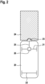
- Fig. 2 shows a conventional mobile platform 20 with a front (drive) axle 21 and a rear (drive) axle 22.
- a distance sensor 23 which is used to detect obstacles and/or people in the path of the mobile platform 20 and which is approved in particular as a safety sensor.
- This protective sensor 23 offers the possibility of defining a safety area 24. As soon as an obstacle and in particular a person can be detected in this safety area 24, this is signaled to the drive 26 of the mobile platform via an interface 25. The mobile platform 20 reacts to this by slowing down the speed or by braking.
- the mobile platform 20 is operated in such a way that the maximum permissible speed is made dependent on how great the distance is to objects transverse to the direction of travel, i.e. how great the distance is to lateral obstacles.
- these lateral obstacles are in particular the walls of the corridor system.
- the mobile platform 20 is operated in such a way that the maximum speed is low when the mobile platform is close to a wall.
- the permissible maximum speed is higher.
- Fig. 1 Due to the proximity to the wall, it has a limited "field of vision" of the intersection, as in Fig. 1 is illustrated.
- the reduced speed prevents an unforeseen collision at the intersection.
- no object perpendicular to the direction of travel i.e. no lateral obstacle at a short distance
- the field of view of the sensor is no longer restricted, so that the speed can be controlled depending on objects within the protection area 24 in accordance with the usual function of the safety sensor 23.
- the distance to lateral obstacles i.e. in particular to a side wall or to both side walls, inevitably narrows, so that here too dangerous situations are defused by the inventive reduction in the maximum speed.
- a prerequisite for the method according to the invention is that the sensors provided on the mobile unit or the sensor can detect lateral objects, i.e. objects perpendicular to the direction of travel.
- this function can be fulfilled by a sensor arranged at the front, for example sensor 23.
- sensor 23 a sensor arranged at the front
- separate sensors are provided for this purpose.
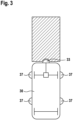
- Fig. 3 illustrates a mobile platform 30 with four laterally arranged sensors 37 which are used for the purposes of the invention. These can be the same type of sensors that are also used for the frontally arranged protective sensor 33, which is representative of conventional frontally aligned protective distance sensors. However, other types of sensors can also be used for this purpose.
- the obstacles that can be detected at the side are differentiated in such a way that there is no reduction in speed for very narrow or small objects at the side.
- This can be done by appropriate filtering or smoothing of the detected signals.
- the smoothing can be done by forming a median value or an average value of the wall distances of the last second. This prevents, for example, a pillar, door frame or similar arranged at the side from causing a reduction in the maximum speed that is actually not necessary.
- the actual direction of travel or the steering angle of the mobile platform can also be taken into account in the method according to the invention, although this places special demands on the sensor system that measures the distance to lateral obstacles. Depending on the direction of travel, the measurement is directed in a different direction.
- the method according to the invention can also be combined with devices that ensure that a minimum distance to lateral obstacles, in particular to lateral parts of the building, is maintained. For example, if a critical distance to the wall is not reached, the travel path can, if possible, be corrected in such a way that the Distance to the wall is increased. Furthermore, the platform can be made to stop or slow down significantly if the distance to side obstacles (e.g. wall) falls below a critical level. The position is then re-determined exactly. The platform can then continue driving after correcting the distance.
- side obstacles e.g. wall
Landscapes
- Engineering & Computer Science (AREA)
- Transportation (AREA)
- Mechanical Engineering (AREA)
- Automation & Control Theory (AREA)
- Aviation & Aerospace Engineering (AREA)
- Radar, Positioning & Navigation (AREA)
- Remote Sensing (AREA)
- Physics & Mathematics (AREA)
- General Physics & Mathematics (AREA)
- Control Of Position, Course, Altitude, Or Attitude Of Moving Bodies (AREA)
Description
- Die vorliegende Erfindung betrifft ein Verfahren zum Betreiben einer selbstbeweglichen mobilen Plattform mit wenigstens einem Sensor zur Detektion von Hindernissen in der Umgebung der mobilen Plattform. Weiterhin betrifft die Erfindung eine selbstbewegliche mobile Plattform sowie ein Computerprogramm, ein maschinenlesbares Speichermedium mit einem Computerprogramm und ein elektronisches Steuergerät, die zur Durchführung des erfindungsgemäßen Verfahrens geeignet sind.
- In verschiedenen Bereichen kommen autonom fahrende, selbstbewegliche mobile Plattformen zum Einsatz, beispielsweise als Flurförderzeuge in der industriellen Fertigung oder Lagerung oder als Transportroboter in Krankenhäusern, Pflegeheimen oder Ähnlichem (fahrerlose Transportsysteme - FTS). Bei dem Betrieb von selbstbeweglichen mobilen Plattformen müssen verschiedene Sicherheitsaspekte berücksichtigt werden. Das Sicherheitskonzept von autonom fahrenden Plattformen sollte dabei so ausgelegt sein, dass diese Fahrzeuge nicht oder, wenn überhaupt, nur mit geringer Geschwindigkeit mit Hindernissen und anderen fahrenden Plattformen kollidieren können. In diesem Zusammenhang wird eine Geschwindigkeit der mobilen Plattform unter 0,3 m/s als unkritisch angesehen. Weiterhin muss das Sicherheitskonzept gewährleisten, dass Kollisionen mit Personen sicher vermieden werden. Auch in diesem Zusammenhang wird eine Geschwindigkeit unter 0,3 m/s als unkritisch angesehen.
- Für einen sicheren Betrieb der mobilen Plattformen wird eine geeignete Sensorik eingesetzt, sodass Hindernisse rechtzeitig erkannt werden können und die mobile Plattform entsprechend reagieren kann. Beispielsweise werden Abstandssensoren verwendet, die auf der Basis von Wellenlaufzeitmessungen frontale Hindernisse erkennen können. Der Fahrweg der mobilen Plattform kann damit entsprechend geplant und angepasst und Hindernisse, beispielsweise auch Menschen, umfahren werden. Je höher die Fahrgeschwindigkeit der mobilen Plattform ist, umso früher muss eine drohende Kollision erkannt werden, damit das Fahrzeug entsprechend abgebremst und/oder umgeleitet werden kann.
- Üblicherweise sind selbstbewegliche mobile Plattformen mit einem Personenschutzsensorsystem ausgestattet, wobei mithilfe von insbesondere berührungslos arbeitenden Sensoren Personen detektiert werden können, die sich im Fahrweg befinden. Auf der Basis von solchen Sicherheitssensoren kann ein Sicherheitsbereich definiert werden. Sobald eine Person in diesem Sicherheitsbereich detektierbar ist, kann dies über eine Schnittstelle dem Antrieb der mobilen Plattform signalisiert werden, sodass die mobile Plattform anhalten oder langsamer fahren kann.
- Besonders problematisch für einen sicheren Betrieb ist die Einschränkung des Sichtfeldes der erwähnten Sicherheitssensoren beim Einfahren in einen Kreuzungsbereich. Die Gangwände verhindern die "Sicht" der Abstandssensoren auf mögliche nahende Hindernisse (Personen), die sich innerhalb eines einmündenden Ganges auf die Kreuzung zu bewegen. Oftmals wird daher vor dem Einfahren in einen Kreuzungsbereich die maximale Geschwindigkeit abgesenkt und nach Passieren der Kreuzung wieder erhöht. Damit die mobile Plattform den Kreuzungsbereich überhaupt erkennen kann, muss entweder eine externe Kennzeichnung der Kreuzung durch entsprechende Markierungen, beispielsweise durch RFID-Markierungen (RFID - radio frequency identification) oder optische Marken, vorhanden sein oder das Erkennen der Kreuzung muss durch interne Maßnahmen innerhalb der mobilen Plattform realisiert werden, beispielsweise durch eine permanente Lokalisierung der mobilen Plattform in Bezug zu Umgebungsdaten. Beide Lösungen sind verhältnismäßig aufwendig, da zusätzliche Infrastrukturmaßnahmen erforderlich sind, die darüber hinaus als sicherheitsrelevante Maßnahmen überprüft und überwacht werden müssen.
- Die deutsche Patentanmeldungsschrift
DE 11 2011 104 645 T5 beschreibt einen mobilen Roboter, der als fahrerloses Transportfahrzeug eingesetzt werden kann, wobei dieser Roboter mit einem Totzonensensor und insbesondere einem rotierenden Bildgebungssensor ausgestattet ist. Mithilfe dieses Sensors können bildgebende Signale entlang der Fahrtrichtung aufgenommen werden, um den Standort eines Objektes in der Umgebung des Roboters erfassen und den Roboter entsprechend manövrieren zu können. Die US-PatentanmeldungsschriftUS 2009/0292393 A1 befasst sich mit einem Reinigungsroboter. Um eine Reinigung im Wandbereich vornehmen zu können, weist der Reinigungsroboter einen Wandfolge-Modus auf, wobei mit einem entsprechenden Sensorsystem eine Wand detektiert wird und der Roboter an der Wand entlang geführt wird. Die europäische PatentanmeldungsschriftEP 2 120 122 A1 befasst sich ebenfalls mit einem mobilen Reinigungsroboter, der mit Näherungssensoren zur Detektion von Hindernissen ausgestattet ist. Sobald hiermit ein Hindernis detektiert wird, kann als Reaktion hierauf die Geschwindigkeit des Roboters reduziert werden. - Die US-Patentanmeldungsschrift
US 2014/0095009 A1 beschreibt eine Routenführung für einen autonom beweglichen Körper, wobei eine Geschwindigkeitsentscheidungseinrichtung im Zusammenspiel mit den Bremsbedingungen und der Lokalisierung über die Geschwindigkeit entscheidet, um vor der Kollision mit einem Hindernis stoppen zu können. Die US-PatentanmeldungsschriftUS 2009/0043440 A1 befasst sich mit einer autonomen mobilen Einrichtung, die mit einer Sensoreinheit für Hindernisse ausgestattet ist, sodass Kollisionen vermieden werden können. Die US-PatentanmeldungsschriftUS 2008/0162027 A1 hat ein System zum Gegenstand, das es Fahrzeugen ermöglichen soll, den Verkehrsregeln in Straßensystemen zu folgen, wobei das Fahrzeug unter anderem mit einem Sensor zur Detektion von Objekten in der Umgebung des Fahrzeugs ausgestattet ist, sodass bei einem Fussgänger in der Nähe die Geschwindigkeit gestoppt oder reduziert werden kann. - Das erfindungsgemäße Verfahren ist zum Betreiben einer selbstbeweglichen mobilen Plattform vorgesehen, die wenigstens einen Sensor zur Detektion von Hindernissen in der Umgebung der mobilen Plattform und Schutzabstandssensoren aufweist. Bei dem erstgenannten Sensor handelt es sich insbesondere um einen Abstandssensor, der beispielsweise auf dem Prinzip einer Laufzeitmessung von ausgesendeten Messimpulsen, beispielsweise elektromagnetischen Wellen oder akustischen Wellen, beruht. Erfindungsgemäß wird eine Abstandsmessung zwischen der mobilen Plattform und seitlichen Hindernissen, die sich längs des Fahrweges der mobilen Plattform befinden, vorgenommen. Die Geschwindigkeit und insbesondere die maximale Geschwindigkeit der mobilen Plattform wird in Abhängigkeit von diesem Abstand reduziert. Insbesondere wird die Geschwindigkeit umso stärker reduziert umso geringer der Abstand ist. Die Erfindung geht dabei davon aus, dass es im Allgemeinen günstiger ist, einen größeren Abstand zu seitlichen Hindernissen, insbesondere zu den Seitenwänden eines Ganges einzuhalten. Wenn der Abstand zu einer Gangwand oder anderen sichteinschränkenden Gebäudeteilen oder Objekten in Längsrichtung des Fahrweges zu gering ist, kommt es zu einer besonderen Sichteinschränkung, wenn die mobile Plattform in einen Kreuzungsbereich einfährt. Unter "Sichteinschränkung" ist hierbei zu verstehen, dass das Sichtfeld eines Sicherheitssensors der mobilen Plattform, der auf frontale Hindernisse ausgerichtet ist und der zur Vermeidung von Kollisionen eingesetzt wird, eingeschränkt ist. Je näher sich die mobile Plattform seitlich an einem Gebäudeteil oder einem anderen Objekt befindet und umso mehr dadurch das Sichtfeld dieser Sensorik eingeschränkt ist, umso stärker wird erfindungsgemäß die Geschwindigkeit reduziert. Auf diese Weise können Gefahrensituationen, insbesondere in Kreuzungsbereichen, entschärft werden. Kollisionen in einem Kreuzungsbereich können vermieden werden, da durch die reduzierte Geschwindigkeit die Möglichkeit eines rechtzeitigen Anhaltens oder Ausweichens der mobilen Plattform besteht. Andererseits kann aufgrund der reduzierten Geschwindigkeit der mobilen Plattform auch das sich nähernde Objekt, insbesondere eine Person, rechtzeitig ausweichen. Auch unabhängig von der besonderen Situation an Kreuzungen ist das erfindungsgemäße Verfahren vorteilhaft. Beim Befahren eines Ganges (ohne Kreuzung) bringt es Vorteile, wenn die Geschwindigkeit bei einem geringen Abstand zu einer Wand oder anderen seitlichen Objekten reduziert wird. Mithilfe der erfindungsgemäßen Maßnahme wird die (maximale) Geschwindigkeit an Engstellen verlangsamt. Engstellen zeichnen sich dadurch aus, dass der Abstand zu seitlichen Hindernissen verringert ist. Erfindungsgemäß wird in diesen Situationen die Geschwindigkeit verlangsamt. Wenn also beispielsweise der Gang verhältnismäßig eng wird, wird die Geschwindigkeit verlangsamt bzw. die maximale Geschwindigkeit reduziert, sodass bei einem Zusammentreffen der mobilen Plattform mit Personen diese Personen ausreichend Zeit haben, die Engstelle zu verlassen oder der mobilen Plattform entsprechend auszuweichen.
- Insgesamt erlaubt das erfindungsgemäße Verfahren einen Betrieb der mobilen Plattform, bei dem in potenziellen Gefahrensituationen die Geschwindigkeit reduziert bzw. angepasst wird, ohne dass hierfür weitere Infrastrukturmaßnahmen erforderlich wären. Außerhalb von derartigen potenziellen Gefahrensituationen, also insbesondere außerhalb von Kreuzungsbereichen und außerhalb von Engstellen, kann sich die mobile Plattform mit einer uneingeschränkten maximalen Geschwindigkeit fortbewegen, sodass die Wirtschaftlichkeit gewährleistet ist. Dieses Wegfallen von zusätzlichen Infrastrukturmaßnahmen ist auch im Hinblick auf Sicherheitsüberprüfungen sehr vorteilhaft. Die Verlangsamung der Geschwindigkeit stellt eine sicherheitsrelevante Maßnahme dar, die daher entsprechenden Sicherheitsnormen genügen muss. Dadurch, dass weder aufwendige Algorithmen noch anderweitige zusätzliche Infrastrukturmaßnahmen erforderlich sind, ist auch eine Überprüfung dieser Funktion ohne großen Aufwand möglich.
- Unabhängig von den beschriebenen Maßnahmen können natürlich auch andere sicherheitsrelevante Maßnahmen eingesetzt werden, insbesondere eine optische oder akustische Warnsignalgebung der mobilen Plattform oder Maßnahmen zur Lokalisierung der Plattform oder andere externe Infrastrukturmaßnahmen.
- Im Prinzip ist es möglich, dass die bei herkömmlichen mobilen Plattformen vorgesehenen Schutzabstandssensoren, die insbesondere zur Vermeidung von Kollisionen mit frontalen Hindernissen verwendet werden, auch im Sinne der Erfindung, d.h. also zur Abstandsmessung im Hinblick auf längs des Fahrweges angeordnete Hindernisse, eingesetzt werden. Für das erfindungsgemäße Verfahren werden hierfür jedoch ein oder mehrere separate Sensoren eingesetzt, die unabhängig von den vorhandenen anderen Schutzabstandssensoren der mobilen Plattform für die Zwecke des erfindungsgemäßen Verfahrens eingesetzt werden. Je nach Ausgestaltung und Sende- und Empfangsrichtung der Sensoren können diese separaten Sensoren entsprechend auf der mobilen Plattform positioniert werden. Insbesondere können diese Sensoren im seitlichen Bereich der mobilen Plattform angeordnet sein. Wichtig hierbei ist, dass die Sensoren eine Abstandsmessung zu Objekten quer zur Fahrtrichtung, also zu seitlich auftretenden Hindernissen bzw. zu längs des Fahrweges angeordneten Hindernissen, vornehmen können. Es kann vorgesehen sein, dass diese separaten Sensoren und die anderen Schutzabstandssensoren von im Prinzip gleicher Bauart sind. Es können hierfür aber auch unterschiedliche Sensorarten eingesetzt werden.
- Erfindungsgemäß werden die Signale der Detektion von längs des Fahrweges angeordneten Hindernissen derart ausgewertet und/oder gefiltert, dass eine Mindestgröße und/oder Mindestlänge der Hindernisse erkannt werden kann. Nur bei dem Erreichen dieser Mindestgröße und/oder Mindestlänge wird die Reduktion der maximalen Geschwindigkeit der mobilen Plattform ausgelöst. Durch diese Auswertung (Glättung) der Signale wird verhindert, dass bei schmalen Objekten, wie beispielsweise einer Säule oder einer Türzarge, in unnötiger Weise eine Verlangsamung erzwungen wird.
- In einer bevorzugten Ausführungsform des erfindungsgemäßen Verfahrens wird die Fahrtrichtung der mobilen Plattform bei einer Auswertung der Signale der seitlichen Hindernisdetektion berücksichtigt. Es wird also nicht starr angenommen, dass immer nach vorne gefahren wird, sondern der Lenkwinkel und damit die tatsächliche Fahrtrichtung werden berücksichtigt. Je nach Fahrtrichtung erfolgt dann die Abstandsmessung zu seitlichen Hindernissen in eine andere Richtung. Wenn also beispielsweise die mobile Plattform um eine Kurve fährt, wird die Abstandsmessung zur seitlichen Gangwand entsprechend angepasst.
- Vorzugsweise werden die Fahrgeschwindigkeiten der mobilen Plattform je nach Verwendung oder Einsatzgebiet der mobilen Plattform konfiguriert. So können in Abhängigkeit von unterschiedlichen Einsatzumgebungen unterschiedliche Maximalgeschwindigkeiten vorgesehen werden. Es sollte beispielsweise in einem Krankenhaus, in dem mit einem hohen Personenaufkommen zu rechnen ist, die Geschwindigkeit insgesamt etwas langsamer sein als beispielsweise in einem Warenlager. Bei der Konfiguration der Geschwindigkeiten sollten geeignete Maximalgeschwindigkeiten für verschiedene Situationen, insbesondere einerseits für den Normalbetrieb und andererseits für den Betrieb in potentiellen Gefahrensituationen, die sich durch einen engen Abstand zu seitlichen Hindernissen auszeichnen, vorgesehen werden.
- Eine selbstbewegliche mobile Plattform, die gemäß dem erfindungsgemäßen Verfahren betrieben werden kann, muss wenigstens einen Sensor aufweisen, der zur Detektion von längs des Fahrweges angeordneten Hindernissen, also von seitlichen Hindernissen in Bezug auf die Fahrtrichtung der mobilen Plattform, geeignet ist. Hierbei wird die maximale Geschwindigkeit der mobilen Plattform reduziert, wenn der Abstand zu seitlichen Hindernissen einen Mindestabstand unterschreitet. Der Mindestabstand kann beispielsweise für eine Anwendung in Krankenhäusern 20 cm betragen. Es ist möglich, die Geschwindigkeit in Abhängigkeit vom Wandabstand stufenlos zu reduzieren. In anderen Ausgestaltungen kann die Geschwindigkeit in vordefinierten Stufen reduziert werden. Beispielsweise kann eine schrittweise Reduzierung der Geschwindigkeit bei bestimmten Schwellwerten des Abstands (z.B. 20 cm, 15 cm, 10 cm) vorgesehen sein. Die Schwellwerte können äquidistant oder nicht äquidistant vorgegeben werden. Das Gleiche gilt für die jeweils vorgesehene Geschwindigkeitsreduzierung.
- Mit dem erfindungsgemäßen Verfahren werden Gefahrensituationen in Engstellen oder bei der Annäherung an eine Kreuzung, wenn die mobile Plattform sich relativ nah an seitlichen, sichteinschränkenden Objekten befindet, entschärft. Erfindungsgemäß weist die mobile Plattform zusätzlich zu dem oder den Sensor(en) zur Detektion von seitlichen Hindernissen übliche Sensoren zur Detektion von frontalen Hindernissen auf, die in an sich bekannter Weise als Schutzsensoren zur Vermeidung von Kollisionen mit, in Fahrtrichtung gesehen, frontalen Objekten verwendet wird. Die Sensoren sind vorteilhafterweise direkt an den Antrieb der mobilen Plattform angebunden, sodass bei der Detektion von Objekten oder Hindernissen innerhalb definierbarer Schutzbereiche die Geschwindigkeit der mobilen Plattform unmittelbar angepasst, d.h. also reduziert oder auf null gesetzt, werden kann. ergeben sich aus der nachfolgenden Beschreibung von Ausführungsbeispielen in Verbindung mit den Zeichnungen. Hierbei können die einzelnen Merkmale jeweils für sich oder in Kombination miteinander verwirklicht sein.
- Bei der mobilen Plattform kann es sich insbesondere um einen Transportroboter, wie er beispielsweise in Krankenhäusern oder Pflegeeinrichtungen eingesetzt werden kann und der beispielsweise mit weiteren Servicefunktionen ausgestattet sein kann, und/oder um ein Flurförderzeug, wie es beispielsweise in industriellen Lager- oder Fertigungshallen eingesetzt werden kann, handeln. Bei der mobilen Plattform kann es sich beispielsweise auch um einen Roboter handeln, der nicht oder nicht in erster Linie für Transportzwecke konzipiert ist und der beispielsweise keine Ablagefläche für Gegenstände aufweist. Es kann sich beispielsweise um einen reinen Serviceroboter handeln. Es sind jedoch auch andere Verwendungen des erfindungsgemäßen Verfahrens bzw. der entsprechend betriebenen mobilen Plattform möglich.
- Weiterhin umfasst die Erfindung ein Computerprogramm bzw. ein Steuerprogramm für den Betrieb einer mobilen Plattform, das jeden Schritt des erfindungsgemäßen Verfahrens in der beschriebenen Weise durchführt. Darüber hinaus umfasst die Erfindung ein maschinenlesbares Speichermedium, auf welchem dieses Programm gespeichert ist, und schließlich ein elektronisches Steuergerät, das eingerichtet ist, die Schritte des erfindungsgemäßen Verfahrens durchzuführen. Das Steuerprogramm kann ohne Weiteres beispielsweise in bestehende mobile Plattformen integriert werden, sodass die Vorteile des erfindungsgemäßen Verfahrens auch bei bestehenden Systemen genutzt werden können.
- Weitere Merkmale und Vorteile der Erfindung ergeben sich aus der nachfolgenden Beschreibung von Ausführungsbeispielen in Verbindung mit den Zeichnungen. Hierbei können die einzelnen Merkmale jeweils für sich oder in Kombination miteinander verwirklicht sein.
- In den Figuren zeigen:
- Fig. 1
- eine schematische Darstellung einer potenziellen Gefahrensituation in einem Kreuzungsbereich;
- Fig. 2
- eine schematische Darstellung einer herkömmlichen mobilen Plattform mit frontal ausgerichtetem Schutzsensor, und
- Fig. 3
- eine schematische Darstellung einer mobilen Plattform mit seitlich ausgerichteten Abstandssensoren.
-
Fig. 1 illustriert eine potenzielle Gefahrensituation in einem Kreuzungsbereich, die mithilfe des erfindungsgemäßen Verfahrens ohne tatsächliche Gefahren gemeistert werden kann. Die mobile Plattform 1 bewegt sich in autonomer Weise durch ein Gangsystem. Hierbei fährt sie in Pfeilrichtung in einen Kreuzungsbereich ein. Zeitgleich bewegt sich eine Person 2 auf diesen Kreuzungsbereich zu, wobei sich die Person 2 in einem Gang bewegt, der von links in Bezug zur Fahrtrichtung der mobilen Plattform 1 einmündet. Die mobile Plattform 1 ist in üblicher Weise mit einem frontal ausgerichteten Schutzsensor ausgestattet. Bei diesem Schutzsensor oder Sicherheitssensor handelt es sich beispielsweise um einen Laserscanner oder einen Ultraschallsensor, der den Bereich in Fahrtrichtung abtastet. Hierbei ist ein Sicherheitsbereich definierbar. Wenn ein Hindernis, beispielsweise ein physikalisches Objekt oder auch eine Person, in diesem Sicherheitsbereich detektiert wird, wird dies von der mobilen Plattform 1 erkannt und die mobile Plattform kann entsprechend reagieren. Die mobile Plattform 1 kann insbesondere die Geschwindigkeit reduzieren oder anhalten. Darüber hinaus kann ein Ausweichmanöver vorgenommen werden. InFig. 1 ist das "Sichtfeld" des Sicherheitssensors mit 3 bezeichnet. Dieses Sichtfeld repräsentiert zugleich den Sicherheitsbereich. Problematisch bei dieser Situation ist, dass das Sichtfeld 3 des Sicherheitssensors durch die links neben der mobilen Plattform 1 befindliche Gangwand eingeschränkt ist. Die Gangwand schränkt die "Sicht" der mobilen Plattform 1 derart ein, dass die Person 2 nicht "gesehen" wird, obwohl sie sich bereits in räumlicher Nähe zu der mobilen Plattform 1 befindet. Ab einer bestimmten Geschwindigkeit der mobilen Plattform 1 wäre es nicht mehr möglich, dass die mobile Plattform 1 in dieser Situation rechtzeitig verzögert. Herkömmlicherweise wird dieses Problem so gelöst, dass die mobile Plattform bei allen Kreuzungssituationen rechtzeitig verzögert. Hierfür sind herkömmlicherweise verschiedene zusätzliche Infrastrukturmaßnahmen erforderlich. Beispielsweise werden externe Kennzeichen einer Kreuzung, beispielsweise über RFID, im Vorfeld einer Kreuzung verwendet, die über eine entsprechende Sensorik der mobilen Plattform erkannt werden können. Oder das autonome Fahrzeug kann eine Kreuzung beispielsweise anhand der eigenen Position innerhalb einer Karte erkennen. Diese Maßnahmen sind alle verhältnismäßig aufwendig. Erfindungsgemäß wird diese Situation gelöst, indem die maximale Geschwindigkeit der mobilen Plattform in Abhängigkeit von einem Abstand zu den sichteinschränkenden Gebäudeteilen oder Objekten, die sich längs der mobilen Plattform befinden, also quer zur Fahrtrichtung, reduziert wird. Je näher sich die mobile Plattform seitlich an einem Gebäudeteil oder einem anderen Objekt befindet, umso stärker ist das Sichtfeld der Sensorik eingeschränkt. Erfindungsgemäß wird daher die maximale Geschwindigkeit in Abhängigkeit vom Abstand zu solchen seitlichen Hindernissen eingeschränkt. Sobald die mobile Plattform in die Kreuzung einfährt, greift diese erfindungsgemäße Maßnahme nicht mehr. Aber sobald sich die mobile Plattform auf der Kreuzung befindet, ist die Sicht des Sicherheitssensors nicht mehr eingeschränkt, sodass dann die übliche Sicherheitsmaßnahme mittels des im Wesentlichen frontal ausgerichteten Sicherheitssensors eingesetzt werden kann. Das erfindungsgemäße Verfahren geht allgemein davon aus, dass es im Allgemeinen günstiger bzw. sicherer ist, in der Mitte eines Ganges zu fahren als nahe an der Wand. Dies trifft zum einen auf Kreuzungssituationen zu, bei denen die Sicht auf die Kreuzung durch die Nähe zur Wand eingeschränkt ist. Dies trifft zum anderen aber auch allgemein auf Engstellen zu, bei denen durch die engen Räumlichkeiten ein Ausweichen für Personen schwierig ist. Das erfindungsgemäße Verfahren lässt sich dabei ohne zusätzliche Infrastrukturmaßnahmen realisieren, was insbesondere auch im Hinblick auf die Überprüfung von Sicherheitsnormen vorteilhaft ist. - In einem Krankenhaus kann beispielsweise bei einem Abstand zur Wand von 20 cm eine kritische Distanz angenommen werden. Erfindungsgemäß kann es vorgesehen sein, dass die Maximalgeschwindigkeit einer mobilen Plattform dann auf höchstens 1 m/s, vorzugsweise auf höchstens 0,8 m/s beschränkt wird. Die konkrete Ausgestaltung des erfindungsgemäßen Verfahrens, also insbesondere, um welchen Betrag und bei welchem Wandabstand die Geschwindigkeit zu reduzieren ist, kann vor allem von den jeweiligen Eigenschaften der selbstfahrenden Plattform (z.B. Montagepunkte der Sensoren, standardmäßige Maximalgeschwindigkeit der Plattform, maximale Bremsverzögerung) und von den Annahmen über gegebenenfalls auftauchenden Personen (z.B. maximale Gehgeschwindigkeit, Abmaße, Abstand von der Wand) abhängig gemacht werden. Wenn in einem Krankenhaus bei einer Unterschreitung von beispielsweise 20 cm zur seitlichen Gangwand erfindungsgemäß eine Geschwindigkeitsreduzierung vorgenommen wird, kann der Sicherheitsabstand in Bezug auf frontale Hindernisse durchaus größer sein. In Abhängigkeit von der Maximalgeschwindigkeit und dem Bremsvermögen der Plattform kann der Sicherheitsabstand in Bezug auf frontale Hindernisse beispielsweise in einem Bereich von etwa 40 cm (z.B. Krankenhaus) bis zu etwa 200 cm (z.B. Warenlager) gewählt werden.
- Mit dem erfindungsgemäßen Verfahren ist es möglich, auch ohne eine explizite Kreuzungs- und Engstellenerkennung die selbstbewegliche mobile Plattform, also das autonome Fahrzeug, in Gefahrensituationen mit einer reduzierten maximalen Geschwindigkeit, beispielsweise 0,3 m/s, und außerhalb derartiger Situationen mit einer höheren Geschwindigkeit fahren zu lassen. Die reduzierte maximale Geschwindigkeit wird erfindungsgemäß bei einem Unterschreiten eines kritischen Abstands zu seitlichen Hindernissen eingestellt, wobei der kritischen Abstand, je nach Art, Anwendung und Einsatzgebiet der mobilen Plattform, beispielsweise 20 cm betragen kann. Auf diese Weise können Gefahrensituationen an Engstellen oder in Kreuzungsbereichen, wenn das Sichtfeld der mobilen Plattform durch einen zu engen Abstand zur Seitenwand eingeschränkt ist, entschärft werden.
-
Fig. 2 zeigt eine übliche mobile Plattform 20 mit einer vorderen (Antriebs-)achse 21 und einer hinteren (Antriebs-)achse 22. Im Frontbereich der mobilen Plattform befindet sich ein Abstandssensor 23, der zur Detektion von Hindernissen und/oder Personen im Fahrweg der mobilen Plattform 20 eingesetzt wird und der insbesondere als Sicherheitssensor zugelassen ist. Dieser Schutzsensor 23 bietet die Möglichkeit, einen Sicherheitsbereich 24 zu definieren. Sobald ein Hindernis und insbesondere eine Person in diesem Sicherheitsbereich 24 detektierbar sind, wird dies über eine Schnittstelle 25 dem Antrieb 26 der mobilen Plattform signalisiert. Die mobile Plattform 20 reagiert hierauf mit einer Verlangsamung der Geschwindigkeit oder mit einem Abbremsen. Erfindungsgemäß wird die mobile Plattform 20 so betrieben, dass die maximal zulässige Geschwindigkeit davon abhängig gemacht wird, wie groß der Abstand zu Objekten quer zur Fahrtrichtung ist, also wie groß der Abstand zu seitlichen Hindernissen ist. Wenn sich die mobile Plattform in einem Gang bewegt, sind diese seitlichen Hindernisse insbesondere die Wände des Gangsystems. Die mobile Plattform 20 wird so betrieben, dass die Maximalgeschwindigkeit niedrig ist, wenn sich die mobile Plattform nahe einer Wand befindet. Befindet sich die mobile Plattform hingegen in größerer Entfernung zu der Wand oder den Wänden, beispielsweise in der Mitte des Gangs, ist die zulässige Maximalgeschwindigkeit höher. Beim Einfahren der mobilen Plattform 20 in einen Kreuzungsbereich bietet dies den Vorteil, dass die mobile Plattform verhältnismäßig langsam fährt, wenn sie sich nahe an der Wand eines Gangs befindet. Durch die Nähe zur Wand hat sie ein eingeschränktes "Sichtfeld" auf die Kreuzung, wie es inFig. 1 illustriert ist. Durch die reduzierte Geschwindigkeit wird vermieden, dass es zu einer nicht vorhergesehenen Kollision auf der Kreuzung kommt. Sobald die Kreuzung erreicht wird, ist zwar kein Objekt quer zur Fahrtrichtung, also kein seitliches Hindernis in geringem Abstand, mehr detektierbar. In dieser Situation ist aber das Sichtfeld des Sensors nicht mehr eingeschränkt, sodass die Geschwindigkeit in Abhängigkeit von Objekten innerhalb des Schutzbereiches 24 gemäß der üblichen Funktion des Sicherheitssensors 23 gesteuert werden kann. In Engstellen verengt sich der Abstand zu seitlichen Hindernissen, also insbesondere zu einer Seitenwand oder zu beiden Seitenwänden zwangsläufig, sodass auch hier über die erfindungsgemäße Reduzierung der maximalen Geschwindigkeit Gefahrensituationen entschärft werden. - Voraussetzung für das erfindungsgemäße Verfahren ist, dass die an der mobilen Einheit vorgesehenen Sensoren oder der Sensor seitliche Objekte, also Objekte quer zur Fahrtrichtung, erfassen können. Diese Funktion kann prinzipiell von einem frontal angeordneten Sensor, beispielsweise dem Sensor 23, erfüllt werden. Erfindungsgemäß sind hierfür separate Sensoren vorgesehen.
Fig. 3 illustriert eine mobile Plattform 30 mit vier seitlich angeordneten Sensoren 37, die für die Zwecke der Erfindung eingesetzt werden. Es kann sich hierbei um die gleiche Art von Sensoren handeln, die auch für den frontal angeordneten Schutzsensor 33, der stellvertretend für übliche frontal ausgerichtete Schutzabstandssensoren steht, verwendet wird. Es können hierfür jedoch auch andere Arten von Sensoren eingesetzt werden. - Erfindungsgemäß ist es vorgesehen, dass die seitlich detektierbaren Hindernisse insoweit differenziert werden, dass bei sehr schmalen oder kleinen seitlichen Objekten keine Reduzierung der Geschwindigkeit erfolgt. Dies kann durch eine entsprechende Filterung oder Glättung der detektierten Signale erfolgen. Beispielsweise kann die Glättung durch die Bildung eines Medianwertes oder eines Durchschnittswertes der Wandabstände der letzten Sekunde vorgenommen werden. Hierdurch wird vermieden, dass beispielsweise eine seitlich angeordnete Säule, Türzarge oder Ähnliches eine tatsächlich nicht erforderliche Reduzierung der maximalen Geschwindigkeit bewirkt.
- Auch die tatsächliche Fahrtrichtung beziehungsweise der Lenkwinkel der mobilen Plattform kann bei dem erfindungsgemäßen Verfahren berücksichtigt werden, wobei dies gesonderte Anforderungen an das Sensorsystem, welches den Abstand zu seitlichen Hindernissen misst, stellt. Je nach Fahrtrichtung wird die Messung in eine andere Richtung ausgerichtet.
- Das erfindungsgemäße Verfahren kann darüber hinaus mit Einrichtungen kombiniert werden, die dafür sorgen, dass ein Mindestabstand zu seitlichen Hindernissen, insbesondere zu seitlichen Gebäudeteilen eingehalten wird. Beispielsweise kann bei einem Unterschreiten eines kritischen Abstands zur Wand, der Fahrweg, wenn möglich, derart korrigiert werden, dass der Abstand zur Wand vergrößert wird. Weiterhin kann die Plattform bei Unterschreiten eines kritischen Abstandes zu seitlichen Hindernissen (z.B. Wand) veranlasst werden, anzuhalten oder deutlich zu verlangsamen. Die Position wird dann exakt neu bestimmt. Anschließend kann die Plattform nach einer Korrektur des Abstandes weiterfahren.
Claims (6)
- Verfahren zum Betreiben einer selbstbeweglichen mobilen Plattform (1; 20; 30) mit wenigstens einem Sensor (23; 33, 37) zur Detektion von Objekten in der Umgebung der mobilen Plattform, dadurch gekennzeichnet, dass die Geschwindigkeit der mobilen Plattform (1; 20; 30) in Abhängigkeit von einem Abstand zwischen der mobilen Plattform und längs des Fahrweges der mobilen Plattform angeordneten seitlichen Objekten reduziert wird, wobei für die Detektion von längs des Fahrweges angeordneten Objekten ein oder mehrere separate Sensoren (37) vorgesehen sind, die unabhängig von vorhandenen anderen Schutzabstandssensoren (33) der mobilen Plattform (30) eingesetzt werden, um eine Gefahrensituation durch eine Sichteinschränkung der anderen Schutzabstandssensoren (33), die auf frontale Hindernisse ausgerichtet sind, durch seitliche Objekte zu entschärfen, und wobei die Signale der Detektion von längs des Fahrweges angeordneten Objekten derart ausgewertet und/oder gefiltert und/oder geglättet werden, dass eine Mindestgröße und/oder Mindestlänge der Objekte gegeben sein muss, um eine Reduktion der maximalen Geschwindigkeit der mobilen Plattform (1; 20; 30) auszulösen.
- Verfahren nach Anspruch 1, dadurch gekennzeichnet, dass die Fahrtrichtung der mobilen Plattform (1; 20; 30) bei einer Auswertung der Signale der Detektion von längs des Fahrweges angeordneten Objekten berücksichtigt wird.
- Verfahren nach Anspruch 1 oder Anspruch 2, dadurch gekennzeichnet, dass je nach Verwendung der mobilen Plattform (1; 20; 30) die Fahrgeschwindigkeiten der mobilen Plattform konfiguriert werden.
- Computerprogrammprodukt, welches eingerichtet ist, jeden Schritt eines Verfahrens gemäß einem der Ansprüche 1 bis 3 durchzuführen.
- Maschinenlesbares Speichermedium, auf welchem ein Computerprogramm nach Anspruch 4 gespeichert ist.
- Elektronisches Steuergerät, das eingerichtet ist, die Schritte eines Verfahrens gemäß einem der Ansprüche 1 bis 3 durchzuführen.
Applications Claiming Priority (1)
| Application Number | Priority Date | Filing Date | Title |
|---|---|---|---|
| DE102014206086.9A DE102014206086A1 (de) | 2014-03-31 | 2014-03-31 | Verfahren zum Betreiben einer selbstbeweglichen mobilen Plattform |
Publications (4)
| Publication Number | Publication Date |
|---|---|
| EP2927768A2 EP2927768A2 (de) | 2015-10-07 |
| EP2927768A3 EP2927768A3 (de) | 2015-11-18 |
| EP2927768B1 EP2927768B1 (de) | 2020-09-02 |
| EP2927768B2 true EP2927768B2 (de) | 2024-12-25 |
Family
ID=52824013
Family Applications (1)
| Application Number | Title | Priority Date | Filing Date |
|---|---|---|---|
| EP15159858.8A Active EP2927768B2 (de) | 2014-03-31 | 2015-03-19 | Verfahren zum betreiben einer selbstbeweglichen mobilen plattform |
Country Status (3)
| Country | Link |
|---|---|
| US (1) | US9637123B2 (de) |
| EP (1) | EP2927768B2 (de) |
| DE (1) | DE102014206086A1 (de) |
Families Citing this family (12)
| Publication number | Priority date | Publication date | Assignee | Title |
|---|---|---|---|---|
| DE102016201115B3 (de) * | 2016-01-26 | 2017-01-26 | Kuka Roboter Gmbh | Mobile Gehhilfe und Verfahren zum Betreiben einer mobilen Gehhilfe |
| JP6418407B2 (ja) * | 2016-05-06 | 2018-11-07 | トヨタ自動車株式会社 | 車両のブレーキ制御装置 |
| DE102016218738A1 (de) * | 2016-09-28 | 2018-03-29 | Robert Bosch Gmbh | Verfahren zum Betreiben von sich autonom bewegenden Plattformen und Hindernisschutzsensor |
| US10829110B2 (en) * | 2017-10-26 | 2020-11-10 | Robert Bosch Gmbh | Method and device for adapting a driving behavior of a semi, highly or fully automated vehicle |
| US10943477B2 (en) * | 2018-01-10 | 2021-03-09 | International Business Machines Corporation | Dynamically defining a safety zone around a user |
| DE202019101201U1 (de) * | 2019-03-04 | 2020-01-27 | Leuze Electronic Gmbh & Co. Kg | Überwachungsvorrichtung |
| CN110609546B (zh) * | 2019-08-15 | 2023-06-30 | 浙江国自机器人技术股份有限公司 | 拣货装置的防护方法、系统、计算机设备和可读存储介质 |
| CN112572457B (zh) * | 2019-09-27 | 2023-09-26 | 北京京东乾石科技有限公司 | 自动导引车控制方法、装置、介质及电子设备 |
| CN112141100B (zh) * | 2020-09-10 | 2021-09-21 | 恒大新能源汽车投资控股集团有限公司 | 车辆控制方法、装置及车辆 |
| JP7505399B2 (ja) * | 2020-12-24 | 2024-06-25 | トヨタ自動車株式会社 | ロボット制御システム、ロボット制御方法、及びプログラム |
| US11505134B1 (en) | 2021-05-25 | 2022-11-22 | Motional Ad Llc | Automated moving platform |
| DE102023136270B4 (de) * | 2023-12-21 | 2025-11-06 | Sick Ag | Autonom fahrendes Transportsystem und ein Verfahren zum Betrieb eines solchen autonom fahrenden Transportsystems |
Citations (6)
| Publication number | Priority date | Publication date | Assignee | Title |
|---|---|---|---|---|
| DE3730105A1 (de) † | 1987-09-08 | 1989-03-16 | Pietzsch Ibp Gmbh | Verfahren und einrichtung zum sichern eines im raum beweglichen fahrzeugs oder geraets |
| WO1993003399A1 (en) † | 1991-08-07 | 1993-02-18 | Aktiebolaget Electrolux | Obstacle detecting assembly |
| DE10324628A1 (de) † | 2003-05-28 | 2004-12-16 | Daimlerchrysler Ag | Steuerverfahren für einen Roboter |
| EP2506106A1 (de) † | 2009-11-27 | 2012-10-03 | Toyota Jidosha Kabushiki Kaisha | Objekt mit autonomer bewegung und steuerverfahren dafür |
| WO2012164691A1 (ja) † | 2011-05-31 | 2012-12-06 | 株式会社日立製作所 | 自律移動システム |
| DE102011109532A1 (de) † | 2011-08-05 | 2013-02-07 | Sew-Eurodrive Gmbh & Co. Kg | Anlage und Verfahren zum Betreiben einer Anlage |
Family Cites Families (9)
| Publication number | Priority date | Publication date | Assignee | Title |
|---|---|---|---|---|
| JP4028135B2 (ja) * | 1999-05-27 | 2007-12-26 | 本田技研工業株式会社 | 物体検出装置 |
| US8412377B2 (en) | 2000-01-24 | 2013-04-02 | Irobot Corporation | Obstacle following sensor scheme for a mobile robot |
| EP2120122B1 (de) | 2005-12-02 | 2013-10-30 | iRobot Corporation | Abdeckungsrobotermobilität |
| US7375620B2 (en) * | 2005-12-08 | 2008-05-20 | Gm Global Technology Operations, Inc. | Speed-sensitive rear obstacle detection and avoidance system |
| US9302678B2 (en) * | 2006-12-29 | 2016-04-05 | Robotic Research, Llc | Robotic driving system |
| JP4576445B2 (ja) * | 2007-04-12 | 2010-11-10 | パナソニック株式会社 | 自律移動型装置および自律移動型装置用プログラム |
| US8126642B2 (en) * | 2008-10-24 | 2012-02-28 | Gray & Company, Inc. | Control and systems for autonomously driven vehicles |
| US8918213B2 (en) | 2010-05-20 | 2014-12-23 | Irobot Corporation | Mobile human interface robot |
| JP2014509417A (ja) | 2010-12-30 | 2014-04-17 | アイロボット コーポレイション | 可動式ヒューマンインターフェースロボット |
-
2014
- 2014-03-31 DE DE102014206086.9A patent/DE102014206086A1/de not_active Withdrawn
-
2015
- 2015-03-12 US US14/645,900 patent/US9637123B2/en not_active Expired - Fee Related
- 2015-03-19 EP EP15159858.8A patent/EP2927768B2/de active Active
Patent Citations (6)
| Publication number | Priority date | Publication date | Assignee | Title |
|---|---|---|---|---|
| DE3730105A1 (de) † | 1987-09-08 | 1989-03-16 | Pietzsch Ibp Gmbh | Verfahren und einrichtung zum sichern eines im raum beweglichen fahrzeugs oder geraets |
| WO1993003399A1 (en) † | 1991-08-07 | 1993-02-18 | Aktiebolaget Electrolux | Obstacle detecting assembly |
| DE10324628A1 (de) † | 2003-05-28 | 2004-12-16 | Daimlerchrysler Ag | Steuerverfahren für einen Roboter |
| EP2506106A1 (de) † | 2009-11-27 | 2012-10-03 | Toyota Jidosha Kabushiki Kaisha | Objekt mit autonomer bewegung und steuerverfahren dafür |
| WO2012164691A1 (ja) † | 2011-05-31 | 2012-12-06 | 株式会社日立製作所 | 自律移動システム |
| DE102011109532A1 (de) † | 2011-08-05 | 2013-02-07 | Sew-Eurodrive Gmbh & Co. Kg | Anlage und Verfahren zum Betreiben einer Anlage |
Also Published As
| Publication number | Publication date |
|---|---|
| EP2927768A3 (de) | 2015-11-18 |
| EP2927768B1 (de) | 2020-09-02 |
| US9637123B2 (en) | 2017-05-02 |
| DE102014206086A1 (de) | 2015-10-01 |
| EP2927768A2 (de) | 2015-10-07 |
| US20150274165A1 (en) | 2015-10-01 |
Similar Documents
| Publication | Publication Date | Title |
|---|---|---|
| EP2927768B2 (de) | Verfahren zum betreiben einer selbstbeweglichen mobilen plattform | |
| EP3455153B1 (de) | Verfahren und system zur vermeidung von kollisionen bei kränen | |
| DE102008036009B4 (de) | Verfahren zum Kollisionsschutz eines Kraftfahrzeugs und Parkhausassistent | |
| EP3253634B1 (de) | Verarbeiten von sensordaten für ein fahrerassistenzsystem | |
| DE102011014699B4 (de) | Verfahren zum Betrieb eines Fahrerassistenzsystems zum Schutz eines Kraftfahrzeuges vor Beschädigungen und Kraftfahrzeug | |
| DE102011018159A1 (de) | Vorrichtung und Verfahren zur Fahrerunterstützung | |
| EP3537024B1 (de) | System zur kollisionsvermeidung und verfahren zur kollisionsvermeidung | |
| EP3543204A2 (de) | Verfahren zum betreiben eines flurförderzeugs | |
| DE102009009211A1 (de) | Verfahren und Assistenzsystem zum Erfassen von Objekten im Umfeld eines Fahrzeugs | |
| EP2043896A1 (de) | Verfahren und vorrichtung zur vermeidung und/oder minderung der folgen von kollisionen | |
| DE102011116822A1 (de) | Überwachungssystem zur Überwachung des Umfeldes von Fahrzeugen, insbesondere von Kraft- und/oder Nutzfahrzeugen | |
| DE102016115371A1 (de) | Verfahren und vorrichtung zur meidung von rückwärtigem querverkehr | |
| DE102014222900A1 (de) | Betrieb eines Schienenfahrzeugs mit einem Bilderzeugungssystem | |
| EP3586163A1 (de) | Verfahren zum überwachen einer umgebung eines fahrzeugs | |
| DE102018110852A1 (de) | Vorrichtung und Verfahren zur Sicherung eines maschinell oder automatisch gesteuerten beweglichen Gerätes und Sensorkachel | |
| EP2460152B1 (de) | Verfahren zur erhöhung der sicherheit eines fahrzeugs und zentrale verarbeitungseinheit für ein fahrerassistenzsystem | |
| EP3368388B1 (de) | Verfahren zum manövrieren eines kraftfahrzeugs mit bewegen des kraftfahrzeugs in eine erfassungsposition, fahrerassistenzsystem sowie kraftfahrzeug | |
| EP3847333B1 (de) | Torsicherheitssystem zum verhindern von kollisionen zwischen einem fahrzeug und einem tor | |
| DE102015215101A1 (de) | Verfahren und System zum Betreiben einer selbsttätig mobilen Plattform | |
| EP3377715B1 (de) | Verfahren zum steuern eines sich teilautonom bewegenden fahrzeugs innerhalb einer betriebsumgebung und bauwerk dafür | |
| WO2016075146A1 (de) | SCHIENENFAHRZEUG MIT EINEM SENSOR ZUR ERFASSUNG EINES RAUMES AUßERHALB DES SCHIENENFAHRZEUGS UND/ODER MIT EINEM SIGNALGEBER ZUM AUSGEBEN VON SIGNALEN IN DEN RAUM AUßERHALB DES SCHIENENFAHRZEUGS | |
| EP4180380A1 (de) | Verfahren zur hindernisbehandlung in einem flurförderzeug | |
| DE102021108206A1 (de) | Verfahren zum Betreiben eines Flurförderzeugs in einem intralogistischen System und intralogistisches System | |
| EP4223944B1 (de) | System zur kollisionsvermeidung zwischen einer ladeeinrichtung und einem lastfahrzeug | |
| DE102025104555B3 (de) | Verfahren zum be- und/oder entladen eines laderaums, insbesondere des laderaums eines lastkraftwagens, mit einem autonomen ladefahrzeug und absicherungssystem |
Legal Events
| Date | Code | Title | Description |
|---|---|---|---|
| PUAI | Public reference made under article 153(3) epc to a published international application that has entered the european phase |
Free format text: ORIGINAL CODE: 0009012 |
|
| AK | Designated contracting states |
Kind code of ref document: A2 Designated state(s): AL AT BE BG CH CY CZ DE DK EE ES FI FR GB GR HR HU IE IS IT LI LT LU LV MC MK MT NL NO PL PT RO RS SE SI SK SM TR |
|
| AX | Request for extension of the european patent |
Extension state: BA ME |
|
| PUAL | Search report despatched |
Free format text: ORIGINAL CODE: 0009013 |
|
| AK | Designated contracting states |
Kind code of ref document: A3 Designated state(s): AL AT BE BG CH CY CZ DE DK EE ES FI FR GB GR HR HU IE IS IT LI LT LU LV MC MK MT NL NO PL PT RO RS SE SI SK SM TR |
|
| AX | Request for extension of the european patent |
Extension state: BA ME |
|
| RIC1 | Information provided on ipc code assigned before grant |
Ipc: G05D 1/02 20060101AFI20151009BHEP Ipc: B60W 30/14 20060101ALI20151009BHEP |
|
| 17P | Request for examination filed |
Effective date: 20160518 |
|
| RBV | Designated contracting states (corrected) |
Designated state(s): AL AT BE BG CH CY CZ DE DK EE ES FI FR GB GR HR HU IE IS IT LI LT LU LV MC MK MT NL NO PL PT RO RS SE SI SK SM TR |
|
| STAA | Information on the status of an ep patent application or granted ep patent |
Free format text: STATUS: EXAMINATION IS IN PROGRESS |
|
| 17Q | First examination report despatched |
Effective date: 20180503 |
|
| REG | Reference to a national code |
Ref country code: DE Ref legal event code: R079 Ref document number: 502015013357 Country of ref document: DE Free format text: PREVIOUS MAIN CLASS: G05D0001020000 Ipc: B60T0007220000 |
|
| RAP1 | Party data changed (applicant data changed or rights of an application transferred) |
Owner name: ROBERT BOSCH GMBH |
|
| GRAP | Despatch of communication of intention to grant a patent |
Free format text: ORIGINAL CODE: EPIDOSNIGR1 |
|
| STAA | Information on the status of an ep patent application or granted ep patent |
Free format text: STATUS: GRANT OF PATENT IS INTENDED |
|
| RIC1 | Information provided on ipc code assigned before grant |
Ipc: B60T 7/22 20060101AFI20200414BHEP |
|
| INTG | Intention to grant announced |
Effective date: 20200504 |
|
| GRAS | Grant fee paid |
Free format text: ORIGINAL CODE: EPIDOSNIGR3 |
|
| GRAA | (expected) grant |
Free format text: ORIGINAL CODE: 0009210 |
|
| STAA | Information on the status of an ep patent application or granted ep patent |
Free format text: STATUS: THE PATENT HAS BEEN GRANTED |
|
| AK | Designated contracting states |
Kind code of ref document: B1 Designated state(s): AL AT BE BG CH CY CZ DE DK EE ES FI FR GB GR HR HU IE IS IT LI LT LU LV MC MK MT NL NO PL PT RO RS SE SI SK SM TR |
|
| REG | Reference to a national code |
Ref country code: GB Ref legal event code: FG4D Free format text: NOT ENGLISH |
|
| REG | Reference to a national code |
Ref country code: AT Ref legal event code: REF Ref document number: 1308479 Country of ref document: AT Kind code of ref document: T Effective date: 20200915 Ref country code: CH Ref legal event code: EP |
|
| REG | Reference to a national code |
Ref country code: DE Ref legal event code: R096 Ref document number: 502015013357 Country of ref document: DE |
|
| REG | Reference to a national code |
Ref country code: IE Ref legal event code: FG4D Free format text: LANGUAGE OF EP DOCUMENT: GERMAN |
|
| REG | Reference to a national code |
Ref country code: LT Ref legal event code: MG4D |
|
| PG25 | Lapsed in a contracting state [announced via postgrant information from national office to epo] |
Ref country code: LT Free format text: LAPSE BECAUSE OF FAILURE TO SUBMIT A TRANSLATION OF THE DESCRIPTION OR TO PAY THE FEE WITHIN THE PRESCRIBED TIME-LIMIT Effective date: 20200902 Ref country code: GR Free format text: LAPSE BECAUSE OF FAILURE TO SUBMIT A TRANSLATION OF THE DESCRIPTION OR TO PAY THE FEE WITHIN THE PRESCRIBED TIME-LIMIT Effective date: 20201203 Ref country code: SE Free format text: LAPSE BECAUSE OF FAILURE TO SUBMIT A TRANSLATION OF THE DESCRIPTION OR TO PAY THE FEE WITHIN THE PRESCRIBED TIME-LIMIT Effective date: 20200902 Ref country code: BG Free format text: LAPSE BECAUSE OF FAILURE TO SUBMIT A TRANSLATION OF THE DESCRIPTION OR TO PAY THE FEE WITHIN THE PRESCRIBED TIME-LIMIT Effective date: 20201202 Ref country code: NO Free format text: LAPSE BECAUSE OF FAILURE TO SUBMIT A TRANSLATION OF THE DESCRIPTION OR TO PAY THE FEE WITHIN THE PRESCRIBED TIME-LIMIT Effective date: 20201202 Ref country code: HR Free format text: LAPSE BECAUSE OF FAILURE TO SUBMIT A TRANSLATION OF THE DESCRIPTION OR TO PAY THE FEE WITHIN THE PRESCRIBED TIME-LIMIT Effective date: 20200902 Ref country code: FI Free format text: LAPSE BECAUSE OF FAILURE TO SUBMIT A TRANSLATION OF THE DESCRIPTION OR TO PAY THE FEE WITHIN THE PRESCRIBED TIME-LIMIT Effective date: 20200902 |
|
| REG | Reference to a national code |
Ref country code: NL Ref legal event code: MP Effective date: 20200902 |
|
| PG25 | Lapsed in a contracting state [announced via postgrant information from national office to epo] |
Ref country code: RS Free format text: LAPSE BECAUSE OF FAILURE TO SUBMIT A TRANSLATION OF THE DESCRIPTION OR TO PAY THE FEE WITHIN THE PRESCRIBED TIME-LIMIT Effective date: 20200902 Ref country code: LV Free format text: LAPSE BECAUSE OF FAILURE TO SUBMIT A TRANSLATION OF THE DESCRIPTION OR TO PAY THE FEE WITHIN THE PRESCRIBED TIME-LIMIT Effective date: 20200902 Ref country code: PL Free format text: LAPSE BECAUSE OF FAILURE TO SUBMIT A TRANSLATION OF THE DESCRIPTION OR TO PAY THE FEE WITHIN THE PRESCRIBED TIME-LIMIT Effective date: 20200902 |
|
| PG25 | Lapsed in a contracting state [announced via postgrant information from national office to epo] |
Ref country code: CZ Free format text: LAPSE BECAUSE OF FAILURE TO SUBMIT A TRANSLATION OF THE DESCRIPTION OR TO PAY THE FEE WITHIN THE PRESCRIBED TIME-LIMIT Effective date: 20200902 Ref country code: RO Free format text: LAPSE BECAUSE OF FAILURE TO SUBMIT A TRANSLATION OF THE DESCRIPTION OR TO PAY THE FEE WITHIN THE PRESCRIBED TIME-LIMIT Effective date: 20200902 Ref country code: SM Free format text: LAPSE BECAUSE OF FAILURE TO SUBMIT A TRANSLATION OF THE DESCRIPTION OR TO PAY THE FEE WITHIN THE PRESCRIBED TIME-LIMIT Effective date: 20200902 Ref country code: EE Free format text: LAPSE BECAUSE OF FAILURE TO SUBMIT A TRANSLATION OF THE DESCRIPTION OR TO PAY THE FEE WITHIN THE PRESCRIBED TIME-LIMIT Effective date: 20200902 Ref country code: NL Free format text: LAPSE BECAUSE OF FAILURE TO SUBMIT A TRANSLATION OF THE DESCRIPTION OR TO PAY THE FEE WITHIN THE PRESCRIBED TIME-LIMIT Effective date: 20200902 Ref country code: PT Free format text: LAPSE BECAUSE OF FAILURE TO SUBMIT A TRANSLATION OF THE DESCRIPTION OR TO PAY THE FEE WITHIN THE PRESCRIBED TIME-LIMIT Effective date: 20210104 |
|
| REG | Reference to a national code |
Ref country code: DE Ref legal event code: R026 Ref document number: 502015013357 Country of ref document: DE |
|
| PLBI | Opposition filed |
Free format text: ORIGINAL CODE: 0009260 |
|
| PG25 | Lapsed in a contracting state [announced via postgrant information from national office to epo] |
Ref country code: IS Free format text: LAPSE BECAUSE OF FAILURE TO SUBMIT A TRANSLATION OF THE DESCRIPTION OR TO PAY THE FEE WITHIN THE PRESCRIBED TIME-LIMIT Effective date: 20210102 Ref country code: AL Free format text: LAPSE BECAUSE OF FAILURE TO SUBMIT A TRANSLATION OF THE DESCRIPTION OR TO PAY THE FEE WITHIN THE PRESCRIBED TIME-LIMIT Effective date: 20200902 Ref country code: ES Free format text: LAPSE BECAUSE OF FAILURE TO SUBMIT A TRANSLATION OF THE DESCRIPTION OR TO PAY THE FEE WITHIN THE PRESCRIBED TIME-LIMIT Effective date: 20200902 |
|
| PLAX | Notice of opposition and request to file observation + time limit sent |
Free format text: ORIGINAL CODE: EPIDOSNOBS2 |
|
| 26 | Opposition filed |
Opponent name: GHOST IP GMBH Effective date: 20210526 |
|
| PG25 | Lapsed in a contracting state [announced via postgrant information from national office to epo] |
Ref country code: SK Free format text: LAPSE BECAUSE OF FAILURE TO SUBMIT A TRANSLATION OF THE DESCRIPTION OR TO PAY THE FEE WITHIN THE PRESCRIBED TIME-LIMIT Effective date: 20200902 |
|
| PG25 | Lapsed in a contracting state [announced via postgrant information from national office to epo] |
Ref country code: DK Free format text: LAPSE BECAUSE OF FAILURE TO SUBMIT A TRANSLATION OF THE DESCRIPTION OR TO PAY THE FEE WITHIN THE PRESCRIBED TIME-LIMIT Effective date: 20200902 Ref country code: SI Free format text: LAPSE BECAUSE OF FAILURE TO SUBMIT A TRANSLATION OF THE DESCRIPTION OR TO PAY THE FEE WITHIN THE PRESCRIBED TIME-LIMIT Effective date: 20200902 |
|
| PLBB | Reply of patent proprietor to notice(s) of opposition received |
Free format text: ORIGINAL CODE: EPIDOSNOBS3 |
|
| PG25 | Lapsed in a contracting state [announced via postgrant information from national office to epo] |
Ref country code: IT Free format text: LAPSE BECAUSE OF FAILURE TO SUBMIT A TRANSLATION OF THE DESCRIPTION OR TO PAY THE FEE WITHIN THE PRESCRIBED TIME-LIMIT Effective date: 20200902 Ref country code: MC Free format text: LAPSE BECAUSE OF FAILURE TO SUBMIT A TRANSLATION OF THE DESCRIPTION OR TO PAY THE FEE WITHIN THE PRESCRIBED TIME-LIMIT Effective date: 20200902 |
|
| REG | Reference to a national code |
Ref country code: CH Ref legal event code: PL |
|
| GBPC | Gb: european patent ceased through non-payment of renewal fee |
Effective date: 20210319 |
|
| REG | Reference to a national code |
Ref country code: BE Ref legal event code: MM Effective date: 20210331 |
|
| PG25 | Lapsed in a contracting state [announced via postgrant information from national office to epo] |
Ref country code: IE Free format text: LAPSE BECAUSE OF NON-PAYMENT OF DUE FEES Effective date: 20210319 Ref country code: GB Free format text: LAPSE BECAUSE OF NON-PAYMENT OF DUE FEES Effective date: 20210319 Ref country code: FR Free format text: LAPSE BECAUSE OF NON-PAYMENT OF DUE FEES Effective date: 20210331 Ref country code: LU Free format text: LAPSE BECAUSE OF NON-PAYMENT OF DUE FEES Effective date: 20210319 Ref country code: LI Free format text: LAPSE BECAUSE OF NON-PAYMENT OF DUE FEES Effective date: 20210331 Ref country code: CH Free format text: LAPSE BECAUSE OF NON-PAYMENT OF DUE FEES Effective date: 20210331 |
|
| REG | Reference to a national code |
Ref country code: AT Ref legal event code: MM01 Ref document number: 1308479 Country of ref document: AT Kind code of ref document: T Effective date: 20210319 |
|
| PG25 | Lapsed in a contracting state [announced via postgrant information from national office to epo] |
Ref country code: BE Free format text: LAPSE BECAUSE OF NON-PAYMENT OF DUE FEES Effective date: 20210331 |
|
| PG25 | Lapsed in a contracting state [announced via postgrant information from national office to epo] |
Ref country code: AT Free format text: LAPSE BECAUSE OF NON-PAYMENT OF DUE FEES Effective date: 20210319 |
|
| APAH | Appeal reference modified |
Free format text: ORIGINAL CODE: EPIDOSCREFNO |
|
| APBM | Appeal reference recorded |
Free format text: ORIGINAL CODE: EPIDOSNREFNO |
|
| APBP | Date of receipt of notice of appeal recorded |
Free format text: ORIGINAL CODE: EPIDOSNNOA2O |
|
| APBQ | Date of receipt of statement of grounds of appeal recorded |
Free format text: ORIGINAL CODE: EPIDOSNNOA3O |
|
| PG25 | Lapsed in a contracting state [announced via postgrant information from national office to epo] |
Ref country code: HU Free format text: LAPSE BECAUSE OF FAILURE TO SUBMIT A TRANSLATION OF THE DESCRIPTION OR TO PAY THE FEE WITHIN THE PRESCRIBED TIME-LIMIT; INVALID AB INITIO Effective date: 20150319 |
|
| PG25 | Lapsed in a contracting state [announced via postgrant information from national office to epo] |
Ref country code: CY Free format text: LAPSE BECAUSE OF FAILURE TO SUBMIT A TRANSLATION OF THE DESCRIPTION OR TO PAY THE FEE WITHIN THE PRESCRIBED TIME-LIMIT Effective date: 20200902 |
|
| PLAB | Opposition data, opponent's data or that of the opponent's representative modified |
Free format text: ORIGINAL CODE: 0009299OPPO |
|
| R26 | Opposition filed (corrected) |
Opponent name: GHOST IP GMBH Effective date: 20210526 |
|
| PG25 | Lapsed in a contracting state [announced via postgrant information from national office to epo] |
Ref country code: MK Free format text: LAPSE BECAUSE OF FAILURE TO SUBMIT A TRANSLATION OF THE DESCRIPTION OR TO PAY THE FEE WITHIN THE PRESCRIBED TIME-LIMIT Effective date: 20200902 |
|
| PG25 | Lapsed in a contracting state [announced via postgrant information from national office to epo] |
Ref country code: TR Free format text: LAPSE BECAUSE OF FAILURE TO SUBMIT A TRANSLATION OF THE DESCRIPTION OR TO PAY THE FEE WITHIN THE PRESCRIBED TIME-LIMIT Effective date: 20200902 |
|
| APBU | Appeal procedure closed |
Free format text: ORIGINAL CODE: EPIDOSNNOA9O |
|
| PG25 | Lapsed in a contracting state [announced via postgrant information from national office to epo] |
Ref country code: MT Free format text: LAPSE BECAUSE OF FAILURE TO SUBMIT A TRANSLATION OF THE DESCRIPTION OR TO PAY THE FEE WITHIN THE PRESCRIBED TIME-LIMIT Effective date: 20200902 |
|
| PUAH | Patent maintained in amended form |
Free format text: ORIGINAL CODE: 0009272 |
|
| STAA | Information on the status of an ep patent application or granted ep patent |
Free format text: STATUS: PATENT MAINTAINED AS AMENDED |
|
| 27A | Patent maintained in amended form |
Effective date: 20241225 |
|
| AK | Designated contracting states |
Kind code of ref document: B2 Designated state(s): AL AT BE BG CH CY CZ DE DK EE ES FI FR GB GR HR HU IE IS IT LI LT LU LV MC MK MT NL NO PL PT RO RS SE SI SK SM TR |
|
| REG | Reference to a national code |
Ref country code: DE Ref legal event code: R102 Ref document number: 502015013357 Country of ref document: DE |
|
| PGFP | Annual fee paid to national office [announced via postgrant information from national office to epo] |
Ref country code: DE Payment date: 20250522 Year of fee payment: 11 |