EP2927768B2 - Procédé de fonctionnement d'une plate-forme mobile automatique - Google Patents
Procédé de fonctionnement d'une plate-forme mobile automatique Download PDFInfo
- Publication number
- EP2927768B2 EP2927768B2 EP15159858.8A EP15159858A EP2927768B2 EP 2927768 B2 EP2927768 B2 EP 2927768B2 EP 15159858 A EP15159858 A EP 15159858A EP 2927768 B2 EP2927768 B2 EP 2927768B2
- Authority
- EP
- European Patent Office
- Prior art keywords
- mobile platform
- distance
- speed
- objects
- travel
- Prior art date
- Legal status (The legal status is an assumption and is not a legal conclusion. Google has not performed a legal analysis and makes no representation as to the accuracy of the status listed.)
- Active
Links
Images

Classifications
-
- B—PERFORMING OPERATIONS; TRANSPORTING
- B60—VEHICLES IN GENERAL
- B60W—CONJOINT CONTROL OF VEHICLE SUB-UNITS OF DIFFERENT TYPE OR DIFFERENT FUNCTION; CONTROL SYSTEMS SPECIALLY ADAPTED FOR HYBRID VEHICLES; ROAD VEHICLE DRIVE CONTROL SYSTEMS FOR PURPOSES NOT RELATED TO THE CONTROL OF A PARTICULAR SUB-UNIT
- B60W30/00—Purposes of road vehicle drive control systems not related to the control of a particular sub-unit, e.g. of systems using conjoint control of vehicle sub-units
- B60W30/14—Adaptive cruise control
- B60W30/143—Speed control
-
- B—PERFORMING OPERATIONS; TRANSPORTING
- B60—VEHICLES IN GENERAL
- B60T—VEHICLE BRAKE CONTROL SYSTEMS OR PARTS THEREOF; BRAKE CONTROL SYSTEMS OR PARTS THEREOF, IN GENERAL; ARRANGEMENT OF BRAKING ELEMENTS ON VEHICLES IN GENERAL; PORTABLE DEVICES FOR PREVENTING UNWANTED MOVEMENT OF VEHICLES; VEHICLE MODIFICATIONS TO FACILITATE COOLING OF BRAKES
- B60T7/00—Brake-action initiating means
- B60T7/12—Brake-action initiating means for automatic initiation; for initiation not subject to will of driver or passenger
- B60T7/22—Brake-action initiating means for automatic initiation; for initiation not subject to will of driver or passenger initiated by contact of vehicle, e.g. bumper, with an external object, e.g. another vehicle, or by means of contactless obstacle detectors mounted on the vehicle
-
- G—PHYSICS
- G05—CONTROLLING; REGULATING
- G05D—SYSTEMS FOR CONTROLLING OR REGULATING NON-ELECTRIC VARIABLES
- G05D1/00—Control of position, course, altitude or attitude of land, water, air or space vehicles, e.g. using automatic pilots
- G05D1/60—Intended control result
- G05D1/617—Safety or protection, e.g. defining protection zones around obstacles or avoiding hazards
- G05D1/622—Obstacle avoidance
-
- G—PHYSICS
- G05—CONTROLLING; REGULATING
- G05D—SYSTEMS FOR CONTROLLING OR REGULATING NON-ELECTRIC VARIABLES
- G05D1/00—Control of position, course, altitude or attitude of land, water, air or space vehicles, e.g. using automatic pilots
- G05D1/60—Intended control result
- G05D1/65—Following a desired speed profile
-
- B—PERFORMING OPERATIONS; TRANSPORTING
- B60—VEHICLES IN GENERAL
- B60T—VEHICLE BRAKE CONTROL SYSTEMS OR PARTS THEREOF; BRAKE CONTROL SYSTEMS OR PARTS THEREOF, IN GENERAL; ARRANGEMENT OF BRAKING ELEMENTS ON VEHICLES IN GENERAL; PORTABLE DEVICES FOR PREVENTING UNWANTED MOVEMENT OF VEHICLES; VEHICLE MODIFICATIONS TO FACILITATE COOLING OF BRAKES
- B60T2201/00—Particular use of vehicle brake systems; Special systems using also the brakes; Special software modules within the brake system controller
- B60T2201/02—Active or adaptive cruise control system; Distance control
- B60T2201/022—Collision avoidance systems
-
- B—PERFORMING OPERATIONS; TRANSPORTING
- B60—VEHICLES IN GENERAL
- B60W—CONJOINT CONTROL OF VEHICLE SUB-UNITS OF DIFFERENT TYPE OR DIFFERENT FUNCTION; CONTROL SYSTEMS SPECIALLY ADAPTED FOR HYBRID VEHICLES; ROAD VEHICLE DRIVE CONTROL SYSTEMS FOR PURPOSES NOT RELATED TO THE CONTROL OF A PARTICULAR SUB-UNIT
- B60W2300/00—Indexing codes relating to the type of vehicle
- B60W2300/40—Carts, e.g. trolleys
-
- G—PHYSICS
- G05—CONTROLLING; REGULATING
- G05D—SYSTEMS FOR CONTROLLING OR REGULATING NON-ELECTRIC VARIABLES
- G05D2105/00—Specific applications of the controlled vehicles
- G05D2105/20—Specific applications of the controlled vehicles for transportation
- G05D2105/28—Specific applications of the controlled vehicles for transportation of freight
-
- G—PHYSICS
- G05—CONTROLLING; REGULATING
- G05D—SYSTEMS FOR CONTROLLING OR REGULATING NON-ELECTRIC VARIABLES
- G05D2107/00—Specific environments of the controlled vehicles
- G05D2107/60—Open buildings, e.g. offices, hospitals, shopping areas or universities
- G05D2107/65—Hospitals
-
- G—PHYSICS
- G05—CONTROLLING; REGULATING
- G05D—SYSTEMS FOR CONTROLLING OR REGULATING NON-ELECTRIC VARIABLES
- G05D2107/00—Specific environments of the controlled vehicles
- G05D2107/70—Industrial sites, e.g. warehouses or factories
-
- G—PHYSICS
- G05—CONTROLLING; REGULATING
- G05D—SYSTEMS FOR CONTROLLING OR REGULATING NON-ELECTRIC VARIABLES
- G05D2109/00—Types of controlled vehicles
- G05D2109/10—Land vehicles
Definitions
- the present invention relates to a method for operating a self-propelled mobile platform with at least one sensor for detecting obstacles in the environment of the mobile platform.
- the invention further relates to a self-propelled mobile platform and a computer program, a machine-readable storage medium with a computer program and an electronic control device, which are suitable for carrying out the method according to the invention.
- Autonomous, self-propelled mobile platforms are used in various areas, for example as industrial trucks in industrial production or storage or as transport robots in hospitals, nursing homes or similar (driverless transport systems - AGVs).
- Various safety aspects must be taken into account when operating self-propelled mobile platforms.
- the safety concept of autonomously propelled platforms should be designed in such a way that these vehicles cannot collide with obstacles and other moving platforms or, if at all, only at low speed. In this context, a speed of the mobile platform below 0.3 m/s is considered uncritical.
- the safety concept must ensure that collisions with people are safely avoided. In this context, too, a speed below 0.3 m/s is considered uncritical.
- suitable sensors are used so that obstacles can be detected in good time and the mobile platform can react accordingly.
- distance sensors are used that can detect frontal obstacles based on wave travel time measurements. The path of the mobile platform can thus be planned and adjusted accordingly and obstacles, such as people, can be avoided. The higher the driving speed of the mobile platform, the sooner an impending collision must be detected so that the vehicle can be braked and/or diverted accordingly.
- self-propelled mobile platforms are equipped with a personal protection sensor system, whereby people in the path of travel can be detected using non-contact sensors.
- a safety area can be defined on the basis of such safety sensors. As soon as a person is detected in this safety area, this can be signaled to the drive of the mobile platform via an interface so that the mobile platform can stop or drive more slowly.
- the limitation of the field of view of the safety sensors mentioned when entering an intersection is particularly problematic for safe operation.
- the corridor walls prevent the distance sensors from "seeing" possible approaching obstacles (people) that are moving towards the intersection within an adjoining corridor.
- the maximum speed is therefore often reduced before entering an intersection and increased again after passing the intersection.
- the intersection In order for the mobile platform to be able to recognize the intersection at all, the intersection must either be externally marked with appropriate markings, for example RFID markings (RFID - radio frequency identification ) or optical marks, or the intersection must be recognized by internal measures within the mobile platform, for example by permanently localizing the mobile platform in relation to environmental data. Both solutions are relatively complex, as additional infrastructure measures are required, which must also be checked and monitored as safety-relevant measures.
- the German patent application DE 11 2011 104 645 T5 describes a mobile robot that can be used as a driverless transport vehicle, whereby this robot is equipped with a dead zone sensor and in particular a rotating imaging sensor. With the help of this sensor, imaging signals can be recorded along the direction of travel in order to detect the location of an object in the robot's environment and to be able to maneuver the robot accordingly.
- the US patent application US 2009/0292393 A1 deals with a cleaning robot. In order to be able to clean in the wall area, the cleaning robot has a wall-following mode, whereby a wall is detected with a corresponding sensor system and the robot is guided along the wall.
- the European patent application EP 2 120 122 A1 also deals with a mobile cleaning robot that is equipped with proximity sensors to detect obstacles. As soon as an obstacle is detected, the speed of the robot can be reduced in response.
- the US patent application US 2014/0095009 A1 describes a route guidance for an autonomously moving body, whereby a speed decision device decides on the speed in conjunction with the braking conditions and the localization in order to be able to stop before colliding with an obstacle.
- the US patent application US 2009/0043440 A1 deals with an autonomous mobile device equipped with an obstacle sensing unit so that collisions can be avoided.
- the US patent application US 2008/0162027 A1 is about a system that enables vehicles to follow traffic rules in road systems, whereby the vehicle is equipped, among other things, with a sensor for detecting objects in the vicinity of the vehicle so that the speed can be stopped or reduced if a pedestrian is nearby.
- the method according to the invention is intended for operating a self-propelled mobile platform which has at least one sensor for detecting obstacles in the vicinity of the mobile platform and protective distance sensors.
- the first-mentioned sensor is in particular a distance sensor which is based, for example, on the principle of measuring the transit time of emitted measuring pulses, for example electromagnetic waves or acoustic waves.
- a distance measurement is carried out between the mobile platform and lateral obstacles which are located along the travel path of the mobile platform.
- the speed and in particular the maximum speed of the mobile platform is reduced depending on this distance. In particular, the speed is reduced more the smaller the distance.
- the invention is based on the assumption that it is generally more advantageous to maintain a greater distance from lateral obstacles, in particular from the side walls of a corridor.
- Visual restriction is understood here to mean that the field of view of a safety sensor on the mobile platform, which is aimed at frontal obstacles and is used to avoid collisions, is restricted. The closer the mobile platform is to the side of a building or another object and the more the field of view of this sensor is restricted, the more the speed is reduced according to the invention. In this way, dangerous situations can be defused, especially in intersection areas. Collisions in an intersection area can be avoided because the reduced speed makes it possible for the mobile platform to stop or swerve in time.
- the reduced speed of the mobile platform also allows the approaching object, in particular a person, to swerve in time.
- the method according to the invention is also advantageous regardless of the special situation at intersections.
- the speed is reduced when there is a small distance to a wall or other objects on the side.
- the measure according to the invention slows down the (maximum) speed at narrow points. Narrow passages are characterized by the fact that the distance to lateral obstacles is reduced.
- the speed is slowed down in these situations. For example, if the aisle becomes relatively narrow, the speed is slowed down or the maximum speed is reduced so that if the mobile platform encounters people, these people have enough time to leave the narrow passage or to avoid the mobile platform accordingly.
- the method according to the invention allows the mobile platform to be operated in such a way that the speed is reduced or adjusted in potentially dangerous situations without the need for additional infrastructure measures.
- the mobile platform can move at an unrestricted maximum speed, thus ensuring cost-effectiveness.
- This elimination of additional infrastructure measures is also very advantageous with regard to safety checks. Slowing down the speed is a safety-relevant measure that must therefore meet the relevant safety standards. Since neither complex algorithms nor other additional infrastructure measures are required, this function can also be checked without great effort.
- the protective distance sensors provided on conventional mobile platforms which are used in particular to avoid collisions with frontal obstacles, to also be used in the sense of the invention, i.e. for measuring the distance with regard to obstacles arranged along the travel path.
- one or more separate sensors are used for this purpose, which are used independently of the other protective distance sensors present on the mobile platform for the purposes of the method according to the invention.
- these separate sensors can be positioned accordingly on the mobile platform.
- these sensors can be arranged in the side area of the mobile platform. It is important here that the sensors can measure the distance to objects transverse to the direction of travel, i.e. to obstacles occurring at the side or to obstacles arranged along the travel path.
- these separate sensors and the other protective distance sensors are essentially of the same design. However, different types of sensors can also be used for this purpose.
- the signals from the detection of obstacles arranged along the travel path are evaluated and/or filtered in such a way that a minimum size and/or minimum length of the obstacles can be recognized.
- the reduction in the maximum speed of the mobile platform is only triggered when this minimum size and/or minimum length is reached.
- This evaluation (smoothing) of the signals prevents unnecessary deceleration being forced in the case of narrow objects, such as a column or a door frame.
- the direction of travel of the mobile platform is taken into account when evaluating the signals from the lateral obstacle detection. It is therefore not rigidly assumed that the vehicle always travels forwards, but the steering angle and thus the actual direction of travel are taken into account.
- the distance measurement to lateral obstacles is then carried out in a different direction. For example, if the mobile platform travels around a curve, the distance measurement to the lateral aisle wall is adjusted accordingly.
- the travel speeds of the mobile platform are configured depending on the use or area of application of the mobile platform. Different maximum speeds can be provided depending on different application environments. For example, in a hospital where a high volume of people is to be expected, the overall speed should be somewhat slower than in a warehouse, for example. When configuring the speeds, suitable maximum speeds should be provided for different situations, in particular for normal operation on the one hand and for operation in potentially dangerous situations characterized by a close distance to lateral obstacles on the other.
- a self-propelled mobile platform that can be operated according to the method according to the invention must have at least one sensor that is suitable for detecting obstacles arranged along the travel path, i.e. lateral obstacles in relation to the direction of travel of the mobile platform.
- the maximum speed of the mobile platform is reduced if the distance to lateral obstacles falls below a minimum distance.
- the minimum distance can be 20 cm for use in hospitals, for example. It is possible to reduce the speed continuously depending on the distance from the wall. In other embodiments, the speed can be reduced in predefined steps. For example, a gradual reduction in speed can be provided at certain threshold values of the distance (e.g. 20 cm, 15 cm, 10 cm). The threshold values can be specified equidistantly or not equidistantly. The same applies to the speed reduction provided in each case.
- the method according to the invention is used to defuse dangerous situations in narrow places or when approaching an intersection when the mobile platform is relatively close to lateral objects that restrict visibility.
- the mobile platform in addition to the sensor(s) for detecting lateral obstacles, the mobile platform has conventional sensors for detecting frontal obstacles, which are used in a manner known per se as protective sensors to avoid collisions with frontal objects, viewed in the direction of travel.
- the sensors are advantageously connected directly to the drive of the mobile platform, so that when objects or obstacles are detected within definable protection areas, the speed of the mobile platform can be immediately adjusted, i.e. reduced or set to zero.
- the mobile platform can be, in particular, a transport robot, such as can be used in hospitals or care facilities, for example, and which can be equipped with additional service functions, and/or an industrial truck, such as can be used in industrial warehouses or production halls, for example.
- the mobile platform can also be, for example, a robot that is not or not primarily designed for transport purposes and which, for example, does not have a storage area for objects. It can, for example, be a pure service robot.
- other uses of the method according to the invention or of the correspondingly operated mobile platform are also possible.
- the invention further comprises a computer program or a control program for operating a mobile platform, which carries out each step of the method according to the invention in the manner described.
- the invention comprises a machine-readable storage medium on which this program is stored, and finally an electronic control device that is set up to carry out the steps of the method according to the invention.
- the control program can easily be integrated into existing mobile platforms, for example, so that the advantages of the method according to the invention can also be used in existing systems.
- Fig. 1 illustrates a potential dangerous situation in an intersection area that can be mastered without actual danger using the method according to the invention.
- the mobile platform 1 moves autonomously through a corridor system. In doing so, it enters an intersection area in the direction of the arrow.
- a person 2 moves towards this intersection area, with the person 2 moving in a corridor that opens from the left in relation to the direction of travel of the mobile platform 1.
- the mobile platform 1 is equipped in the usual way with a front-facing protective sensor.
- This protective sensor or safety sensor is, for example, a laser scanner or an ultrasonic sensor that scans the area in the direction of travel.
- a safety area can be defined here.
- the mobile platform 1 can react accordingly.
- the mobile platform 1 can in particular reduce the speed or stop.
- an evasive maneuver can be carried out.
- the "field of view" of the safety sensor is designated 3.
- This field of view also represents the safety area.
- the problem with this situation is that the field of view 3 of the safety sensor is restricted by the corridor wall to the left of the mobile platform 1.
- the corridor wall restricts the "view" of the mobile platform 1 in such a way that the person 2 is not “seen", although he or she is already in spatial proximity to the mobile platform 1.
- the method according to the invention generally assumes that it is generally cheaper or safer to drive in the middle of a corridor than close to the wall. This applies on the one hand to intersection situations in which the view of the intersection is restricted by the proximity to the wall. On the other hand, this also applies generally to narrow passages where it is difficult for people to escape due to the narrow space.
- the method according to the invention can be implemented without additional infrastructure measures, which is particularly advantageous with regard to checking safety standards.
- a critical distance can be assumed at a distance of 20 cm from the wall.
- the maximum speed of a mobile platform is then limited to a maximum of 1 m/s, preferably to a maximum of 0.8 m/s.
- the specific design of the method according to the invention i.e. in particular by what amount and at what distance from the wall the speed is to be reduced, can be made dependent above all on the respective properties of the self-driving platform (e.g. mounting points of the sensors, standard maximum speed of the platform, maximum braking deceleration) and on the assumptions about persons who may appear (e.g. maximum walking speed, dimensions, distance from the wall).
- the safety distance in relation to frontal obstacles can certainly be greater.
- the safety distance in relation to frontal obstacles can be selected, for example, in a range from around 40 cm (e.g. hospital) to around 200 cm (e.g. warehouse).
- the self-propelled mobile platform i.e. the autonomous vehicle
- travel at a reduced maximum speed for example 0.3 m/s
- the reduced maximum speed is set when a critical distance to lateral obstacles is undershot, whereby the critical distance can be, for example, 20 cm, depending on the type, application and area of use of the mobile platform.
- the critical distance can be, for example, 20 cm, depending on the type, application and area of use of the mobile platform.
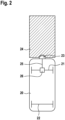
- Fig. 2 shows a conventional mobile platform 20 with a front (drive) axle 21 and a rear (drive) axle 22.
- a distance sensor 23 which is used to detect obstacles and/or people in the path of the mobile platform 20 and which is approved in particular as a safety sensor.
- This protective sensor 23 offers the possibility of defining a safety area 24. As soon as an obstacle and in particular a person can be detected in this safety area 24, this is signaled to the drive 26 of the mobile platform via an interface 25. The mobile platform 20 reacts to this by slowing down the speed or by braking.
- the mobile platform 20 is operated in such a way that the maximum permissible speed is made dependent on how great the distance is to objects transverse to the direction of travel, i.e. how great the distance is to lateral obstacles.
- these lateral obstacles are in particular the walls of the corridor system.
- the mobile platform 20 is operated in such a way that the maximum speed is low when the mobile platform is close to a wall.
- the permissible maximum speed is higher.
- Fig. 1 Due to the proximity to the wall, it has a limited "field of vision" of the intersection, as in Fig. 1 is illustrated.
- the reduced speed prevents an unforeseen collision at the intersection.
- no object perpendicular to the direction of travel i.e. no lateral obstacle at a short distance
- the field of view of the sensor is no longer restricted, so that the speed can be controlled depending on objects within the protection area 24 in accordance with the usual function of the safety sensor 23.
- the distance to lateral obstacles i.e. in particular to a side wall or to both side walls, inevitably narrows, so that here too dangerous situations are defused by the inventive reduction in the maximum speed.
- a prerequisite for the method according to the invention is that the sensors provided on the mobile unit or the sensor can detect lateral objects, i.e. objects perpendicular to the direction of travel.
- this function can be fulfilled by a sensor arranged at the front, for example sensor 23.
- sensor 23 a sensor arranged at the front
- separate sensors are provided for this purpose.
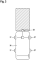
- Fig. 3 illustrates a mobile platform 30 with four laterally arranged sensors 37 which are used for the purposes of the invention. These can be the same type of sensors that are also used for the frontally arranged protective sensor 33, which is representative of conventional frontally aligned protective distance sensors. However, other types of sensors can also be used for this purpose.
- the obstacles that can be detected at the side are differentiated in such a way that there is no reduction in speed for very narrow or small objects at the side.
- This can be done by appropriate filtering or smoothing of the detected signals.
- the smoothing can be done by forming a median value or an average value of the wall distances of the last second. This prevents, for example, a pillar, door frame or similar arranged at the side from causing a reduction in the maximum speed that is actually not necessary.
- the actual direction of travel or the steering angle of the mobile platform can also be taken into account in the method according to the invention, although this places special demands on the sensor system that measures the distance to lateral obstacles. Depending on the direction of travel, the measurement is directed in a different direction.
- the method according to the invention can also be combined with devices that ensure that a minimum distance to lateral obstacles, in particular to lateral parts of the building, is maintained. For example, if a critical distance to the wall is not reached, the travel path can, if possible, be corrected in such a way that the Distance to the wall is increased. Furthermore, the platform can be made to stop or slow down significantly if the distance to side obstacles (e.g. wall) falls below a critical level. The position is then re-determined exactly. The platform can then continue driving after correcting the distance.
- side obstacles e.g. wall
Landscapes
- Engineering & Computer Science (AREA)
- Transportation (AREA)
- Mechanical Engineering (AREA)
- Automation & Control Theory (AREA)
- Aviation & Aerospace Engineering (AREA)
- Radar, Positioning & Navigation (AREA)
- Remote Sensing (AREA)
- Physics & Mathematics (AREA)
- General Physics & Mathematics (AREA)
- Control Of Position, Course, Altitude, Or Attitude Of Moving Bodies (AREA)
Claims (6)
- Procédé d'exploitation d'une plate-forme mobile automotrice (1 ; 20 ; 30), comprenant au moins un capteur (23 ; 33, 37) pour détecter des objets dans l'environnement de la plate-forme mobile, caractérisé en ce que la vitesse de la plate-forme mobile (1 ; 20 ; 30) est réduite en fonction d'une distance entre la plate-forme mobile et des objets latéraux disposés le long du trajet de la plate-forme mobile, dans lequel pour la détection d'objets disposés le long du trajet, un ou plusieurs capteurs séparés (37) sont prévus qui sont mis en œuvre indépendamment d'autres capteurs de distance de sécurité (33) de la plate-forme mobile (30) existants afin de désamorcer par des objets latéraux une situation dangereuse par une limitation du champ visuel des autres capteurs de distance de sécurité (33) qui sont orientés vers des obstacles frontaux, et dans lequel les signaux de la détection d'objets disposés le long du trajet sont évalués et/ou filtrés et/ou lissés de telle sorte qu'une taille minimale et/ou une longueur minimale des objets doivent être données pour déclencher une réduction de la vitesse maximale de la plate-forme mobile (1 ; 20 ; 30).
- Procédé selon la revendication 1, caractérisé en ce que le sens de la marche de la plate-forme mobile (1 ; 20 ; 30) est pris en compte lors d'une évaluation des signaux de la détection d'objets disposés le long du trajet.
- Procédé selon la revendication 1 ou la revendication 2, caractérisé en ce que les vitesses de déplacement de la plate-forme mobile sont configurées en fonction de l'utilisation de la plate-forme mobile (1 ; 20 ; 30).
- Produit de programme informatique, qui est conçu pour effectuer chaque étape d'un procédé selon l'une quelconque des revendications 1 à 3.
- Support de stockage lisible par machine, sur lequel est stocké un programme informatique selon la revendication 4.
- Contrôleur électronique, qui est conçu pour effectuer les étapes d'un procédé selon l'une quelconque des revendications 1 à 3.
Applications Claiming Priority (1)
| Application Number | Priority Date | Filing Date | Title |
|---|---|---|---|
| DE102014206086.9A DE102014206086A1 (de) | 2014-03-31 | 2014-03-31 | Verfahren zum Betreiben einer selbstbeweglichen mobilen Plattform |
Publications (4)
| Publication Number | Publication Date |
|---|---|
| EP2927768A2 EP2927768A2 (fr) | 2015-10-07 |
| EP2927768A3 EP2927768A3 (fr) | 2015-11-18 |
| EP2927768B1 EP2927768B1 (fr) | 2020-09-02 |
| EP2927768B2 true EP2927768B2 (fr) | 2024-12-25 |
Family
ID=52824013
Family Applications (1)
| Application Number | Title | Priority Date | Filing Date |
|---|---|---|---|
| EP15159858.8A Active EP2927768B2 (fr) | 2014-03-31 | 2015-03-19 | Procédé de fonctionnement d'une plate-forme mobile automatique |
Country Status (3)
| Country | Link |
|---|---|
| US (1) | US9637123B2 (fr) |
| EP (1) | EP2927768B2 (fr) |
| DE (1) | DE102014206086A1 (fr) |
Families Citing this family (12)
| Publication number | Priority date | Publication date | Assignee | Title |
|---|---|---|---|---|
| DE102016201115B3 (de) * | 2016-01-26 | 2017-01-26 | Kuka Roboter Gmbh | Mobile Gehhilfe und Verfahren zum Betreiben einer mobilen Gehhilfe |
| JP6418407B2 (ja) * | 2016-05-06 | 2018-11-07 | トヨタ自動車株式会社 | 車両のブレーキ制御装置 |
| DE102016218738A1 (de) * | 2016-09-28 | 2018-03-29 | Robert Bosch Gmbh | Verfahren zum Betreiben von sich autonom bewegenden Plattformen und Hindernisschutzsensor |
| US10829110B2 (en) * | 2017-10-26 | 2020-11-10 | Robert Bosch Gmbh | Method and device for adapting a driving behavior of a semi, highly or fully automated vehicle |
| US10943477B2 (en) * | 2018-01-10 | 2021-03-09 | International Business Machines Corporation | Dynamically defining a safety zone around a user |
| DE202019101201U1 (de) * | 2019-03-04 | 2020-01-27 | Leuze Electronic Gmbh & Co. Kg | Überwachungsvorrichtung |
| CN110609546B (zh) * | 2019-08-15 | 2023-06-30 | 浙江国自机器人技术股份有限公司 | 拣货装置的防护方法、系统、计算机设备和可读存储介质 |
| CN112572457B (zh) * | 2019-09-27 | 2023-09-26 | 北京京东乾石科技有限公司 | 自动导引车控制方法、装置、介质及电子设备 |
| CN112141100B (zh) * | 2020-09-10 | 2021-09-21 | 恒大新能源汽车投资控股集团有限公司 | 车辆控制方法、装置及车辆 |
| JP7505399B2 (ja) * | 2020-12-24 | 2024-06-25 | トヨタ自動車株式会社 | ロボット制御システム、ロボット制御方法、及びプログラム |
| US11505134B1 (en) | 2021-05-25 | 2022-11-22 | Motional Ad Llc | Automated moving platform |
| DE102023136270B4 (de) * | 2023-12-21 | 2025-11-06 | Sick Ag | Autonom fahrendes Transportsystem und ein Verfahren zum Betrieb eines solchen autonom fahrenden Transportsystems |
Citations (6)
| Publication number | Priority date | Publication date | Assignee | Title |
|---|---|---|---|---|
| DE3730105A1 (de) † | 1987-09-08 | 1989-03-16 | Pietzsch Ibp Gmbh | Verfahren und einrichtung zum sichern eines im raum beweglichen fahrzeugs oder geraets |
| WO1993003399A1 (fr) † | 1991-08-07 | 1993-02-18 | Aktiebolaget Electrolux | Ensemble detecteur d'obstacle |
| DE10324628A1 (de) † | 2003-05-28 | 2004-12-16 | Daimlerchrysler Ag | Steuerverfahren für einen Roboter |
| EP2506106A1 (fr) † | 2009-11-27 | 2012-10-03 | Toyota Jidosha Kabushiki Kaisha | Objet mobile autonome et procédé de contrôle |
| WO2012164691A1 (fr) † | 2011-05-31 | 2012-12-06 | 株式会社日立製作所 | Système de déplacement autonome |
| DE102011109532A1 (de) † | 2011-08-05 | 2013-02-07 | Sew-Eurodrive Gmbh & Co. Kg | Anlage und Verfahren zum Betreiben einer Anlage |
Family Cites Families (9)
| Publication number | Priority date | Publication date | Assignee | Title |
|---|---|---|---|---|
| JP4028135B2 (ja) * | 1999-05-27 | 2007-12-26 | 本田技研工業株式会社 | 物体検出装置 |
| US8412377B2 (en) | 2000-01-24 | 2013-04-02 | Irobot Corporation | Obstacle following sensor scheme for a mobile robot |
| KR101300492B1 (ko) | 2005-12-02 | 2013-09-02 | 아이로보트 코퍼레이션 | 커버리지 로봇 이동성 |
| US7375620B2 (en) * | 2005-12-08 | 2008-05-20 | Gm Global Technology Operations, Inc. | Speed-sensitive rear obstacle detection and avoidance system |
| US9302678B2 (en) * | 2006-12-29 | 2016-04-05 | Robotic Research, Llc | Robotic driving system |
| JP4576445B2 (ja) * | 2007-04-12 | 2010-11-10 | パナソニック株式会社 | 自律移動型装置および自律移動型装置用プログラム |
| US8126642B2 (en) * | 2008-10-24 | 2012-02-28 | Gray & Company, Inc. | Control and systems for autonomously driven vehicles |
| US8918213B2 (en) | 2010-05-20 | 2014-12-23 | Irobot Corporation | Mobile human interface robot |
| AU2011352997B2 (en) | 2010-12-30 | 2015-06-18 | Irobot Corporation | Mobile human interface robot |
-
2014
- 2014-03-31 DE DE102014206086.9A patent/DE102014206086A1/de not_active Withdrawn
-
2015
- 2015-03-12 US US14/645,900 patent/US9637123B2/en not_active Expired - Fee Related
- 2015-03-19 EP EP15159858.8A patent/EP2927768B2/fr active Active
Patent Citations (6)
| Publication number | Priority date | Publication date | Assignee | Title |
|---|---|---|---|---|
| DE3730105A1 (de) † | 1987-09-08 | 1989-03-16 | Pietzsch Ibp Gmbh | Verfahren und einrichtung zum sichern eines im raum beweglichen fahrzeugs oder geraets |
| WO1993003399A1 (fr) † | 1991-08-07 | 1993-02-18 | Aktiebolaget Electrolux | Ensemble detecteur d'obstacle |
| DE10324628A1 (de) † | 2003-05-28 | 2004-12-16 | Daimlerchrysler Ag | Steuerverfahren für einen Roboter |
| EP2506106A1 (fr) † | 2009-11-27 | 2012-10-03 | Toyota Jidosha Kabushiki Kaisha | Objet mobile autonome et procédé de contrôle |
| WO2012164691A1 (fr) † | 2011-05-31 | 2012-12-06 | 株式会社日立製作所 | Système de déplacement autonome |
| DE102011109532A1 (de) † | 2011-08-05 | 2013-02-07 | Sew-Eurodrive Gmbh & Co. Kg | Anlage und Verfahren zum Betreiben einer Anlage |
Also Published As
| Publication number | Publication date |
|---|---|
| DE102014206086A1 (de) | 2015-10-01 |
| US20150274165A1 (en) | 2015-10-01 |
| EP2927768A3 (fr) | 2015-11-18 |
| EP2927768B1 (fr) | 2020-09-02 |
| EP2927768A2 (fr) | 2015-10-07 |
| US9637123B2 (en) | 2017-05-02 |
Similar Documents
| Publication | Publication Date | Title |
|---|---|---|
| EP2927768B2 (fr) | Procédé de fonctionnement d'une plate-forme mobile automatique | |
| EP3455153B1 (fr) | Procédé et système pour éviter des collisions par des grues | |
| EP3253634B1 (fr) | Traitement de données de capteur pour un système d'aide à la conduite | |
| DE102011014699B4 (de) | Verfahren zum Betrieb eines Fahrerassistenzsystems zum Schutz eines Kraftfahrzeuges vor Beschädigungen und Kraftfahrzeug | |
| EP3543204B1 (fr) | Procédé de fonctionnement d'un chariot de manutention | |
| DE102011018159A1 (de) | Vorrichtung und Verfahren zur Fahrerunterstützung | |
| DE102009009211A1 (de) | Verfahren und Assistenzsystem zum Erfassen von Objekten im Umfeld eines Fahrzeugs | |
| WO2008009519A1 (fr) | Procédé et dispositif pour prévenir et/ou diminuer les conséquences des collisions | |
| DE102011116822A1 (de) | Überwachungssystem zur Überwachung des Umfeldes von Fahrzeugen, insbesondere von Kraft- und/oder Nutzfahrzeugen | |
| DE102014016815A1 (de) | Verfahren zum Betrieb eines Fahrzeuges | |
| DE102014222900A1 (de) | Betrieb eines Schienenfahrzeugs mit einem Bilderzeugungssystem | |
| EP3537024B1 (fr) | Système permettant d'éviter des collisions et procédé permettant d'éviter des collisions | |
| DE102018110852A1 (de) | Vorrichtung und Verfahren zur Sicherung eines maschinell oder automatisch gesteuerten beweglichen Gerätes und Sensorkachel | |
| EP2460152B1 (fr) | Procédé permettant d'augmenter la sécurité d'un véhicule et unité centrale de traitement destinée à un système d'aide à la conduite | |
| EP3586163A1 (fr) | Procédé de surveillance de l'environnement d'un véhicule | |
| EP3368388B1 (fr) | Procédé de manoeuvre d'un véhicule automobile par déplacement du véhicule automobile dans une position de détection, système d'aide à la conduite et véhicule automobile | |
| EP3847333B1 (fr) | Système de sécurité de porte servant à empêcher des collisions entre un véhicule et une porte | |
| EP4180380A1 (fr) | Procédé de traitement des obstacles dans un chariot de manutention | |
| DE102015215101A1 (de) | Verfahren und System zum Betreiben einer selbsttätig mobilen Plattform | |
| EP3377715B1 (fr) | Procédé de commande d'un véhicule se déplaçant de façon autonome à l'intérieur d'un environnement et construction à cet effet | |
| WO2016075146A1 (fr) | Véhicule ferroviaire muni d'un capteur permettant de détecter un espace situé à l'extérieur du véhicule ferroviaire et/ou d'un émetteur de signaux émettant des signaux dans l'espace situé à l'extérieur du véhicule ferroviaire | |
| EP4464643A1 (fr) | Procédé de traitement d'obstacles dans un chariot de manutention | |
| AT525671B1 (de) | System zur Kollisionsvermeidung zwischen einer Ladeeinrichtung und einem Lastfahrzeug | |
| DE102023136270B4 (de) | Autonom fahrendes Transportsystem und ein Verfahren zum Betrieb eines solchen autonom fahrenden Transportsystems | |
| DE102019220111A1 (de) | Verfahren zum Vermeiden einer Kollision mit anderen Verkehrsteilnehmern und Fahrerassistenzsystem |
Legal Events
| Date | Code | Title | Description |
|---|---|---|---|
| PUAI | Public reference made under article 153(3) epc to a published international application that has entered the european phase |
Free format text: ORIGINAL CODE: 0009012 |
|
| AK | Designated contracting states |
Kind code of ref document: A2 Designated state(s): AL AT BE BG CH CY CZ DE DK EE ES FI FR GB GR HR HU IE IS IT LI LT LU LV MC MK MT NL NO PL PT RO RS SE SI SK SM TR |
|
| AX | Request for extension of the european patent |
Extension state: BA ME |
|
| PUAL | Search report despatched |
Free format text: ORIGINAL CODE: 0009013 |
|
| AK | Designated contracting states |
Kind code of ref document: A3 Designated state(s): AL AT BE BG CH CY CZ DE DK EE ES FI FR GB GR HR HU IE IS IT LI LT LU LV MC MK MT NL NO PL PT RO RS SE SI SK SM TR |
|
| AX | Request for extension of the european patent |
Extension state: BA ME |
|
| RIC1 | Information provided on ipc code assigned before grant |
Ipc: G05D 1/02 20060101AFI20151009BHEP Ipc: B60W 30/14 20060101ALI20151009BHEP |
|
| 17P | Request for examination filed |
Effective date: 20160518 |
|
| RBV | Designated contracting states (corrected) |
Designated state(s): AL AT BE BG CH CY CZ DE DK EE ES FI FR GB GR HR HU IE IS IT LI LT LU LV MC MK MT NL NO PL PT RO RS SE SI SK SM TR |
|
| STAA | Information on the status of an ep patent application or granted ep patent |
Free format text: STATUS: EXAMINATION IS IN PROGRESS |
|
| 17Q | First examination report despatched |
Effective date: 20180503 |
|
| REG | Reference to a national code |
Ref country code: DE Ref legal event code: R079 Ref document number: 502015013357 Country of ref document: DE Free format text: PREVIOUS MAIN CLASS: G05D0001020000 Ipc: B60T0007220000 |
|
| RAP1 | Party data changed (applicant data changed or rights of an application transferred) |
Owner name: ROBERT BOSCH GMBH |
|
| GRAP | Despatch of communication of intention to grant a patent |
Free format text: ORIGINAL CODE: EPIDOSNIGR1 |
|
| STAA | Information on the status of an ep patent application or granted ep patent |
Free format text: STATUS: GRANT OF PATENT IS INTENDED |
|
| RIC1 | Information provided on ipc code assigned before grant |
Ipc: B60T 7/22 20060101AFI20200414BHEP |
|
| INTG | Intention to grant announced |
Effective date: 20200504 |
|
| GRAS | Grant fee paid |
Free format text: ORIGINAL CODE: EPIDOSNIGR3 |
|
| GRAA | (expected) grant |
Free format text: ORIGINAL CODE: 0009210 |
|
| STAA | Information on the status of an ep patent application or granted ep patent |
Free format text: STATUS: THE PATENT HAS BEEN GRANTED |
|
| AK | Designated contracting states |
Kind code of ref document: B1 Designated state(s): AL AT BE BG CH CY CZ DE DK EE ES FI FR GB GR HR HU IE IS IT LI LT LU LV MC MK MT NL NO PL PT RO RS SE SI SK SM TR |
|
| REG | Reference to a national code |
Ref country code: GB Ref legal event code: FG4D Free format text: NOT ENGLISH |
|
| REG | Reference to a national code |
Ref country code: AT Ref legal event code: REF Ref document number: 1308479 Country of ref document: AT Kind code of ref document: T Effective date: 20200915 Ref country code: CH Ref legal event code: EP |
|
| REG | Reference to a national code |
Ref country code: DE Ref legal event code: R096 Ref document number: 502015013357 Country of ref document: DE |
|
| REG | Reference to a national code |
Ref country code: IE Ref legal event code: FG4D Free format text: LANGUAGE OF EP DOCUMENT: GERMAN |
|
| REG | Reference to a national code |
Ref country code: LT Ref legal event code: MG4D |
|
| PG25 | Lapsed in a contracting state [announced via postgrant information from national office to epo] |
Ref country code: LT Free format text: LAPSE BECAUSE OF FAILURE TO SUBMIT A TRANSLATION OF THE DESCRIPTION OR TO PAY THE FEE WITHIN THE PRESCRIBED TIME-LIMIT Effective date: 20200902 Ref country code: GR Free format text: LAPSE BECAUSE OF FAILURE TO SUBMIT A TRANSLATION OF THE DESCRIPTION OR TO PAY THE FEE WITHIN THE PRESCRIBED TIME-LIMIT Effective date: 20201203 Ref country code: SE Free format text: LAPSE BECAUSE OF FAILURE TO SUBMIT A TRANSLATION OF THE DESCRIPTION OR TO PAY THE FEE WITHIN THE PRESCRIBED TIME-LIMIT Effective date: 20200902 Ref country code: BG Free format text: LAPSE BECAUSE OF FAILURE TO SUBMIT A TRANSLATION OF THE DESCRIPTION OR TO PAY THE FEE WITHIN THE PRESCRIBED TIME-LIMIT Effective date: 20201202 Ref country code: NO Free format text: LAPSE BECAUSE OF FAILURE TO SUBMIT A TRANSLATION OF THE DESCRIPTION OR TO PAY THE FEE WITHIN THE PRESCRIBED TIME-LIMIT Effective date: 20201202 Ref country code: HR Free format text: LAPSE BECAUSE OF FAILURE TO SUBMIT A TRANSLATION OF THE DESCRIPTION OR TO PAY THE FEE WITHIN THE PRESCRIBED TIME-LIMIT Effective date: 20200902 Ref country code: FI Free format text: LAPSE BECAUSE OF FAILURE TO SUBMIT A TRANSLATION OF THE DESCRIPTION OR TO PAY THE FEE WITHIN THE PRESCRIBED TIME-LIMIT Effective date: 20200902 |
|
| REG | Reference to a national code |
Ref country code: NL Ref legal event code: MP Effective date: 20200902 |
|
| PG25 | Lapsed in a contracting state [announced via postgrant information from national office to epo] |
Ref country code: RS Free format text: LAPSE BECAUSE OF FAILURE TO SUBMIT A TRANSLATION OF THE DESCRIPTION OR TO PAY THE FEE WITHIN THE PRESCRIBED TIME-LIMIT Effective date: 20200902 Ref country code: LV Free format text: LAPSE BECAUSE OF FAILURE TO SUBMIT A TRANSLATION OF THE DESCRIPTION OR TO PAY THE FEE WITHIN THE PRESCRIBED TIME-LIMIT Effective date: 20200902 Ref country code: PL Free format text: LAPSE BECAUSE OF FAILURE TO SUBMIT A TRANSLATION OF THE DESCRIPTION OR TO PAY THE FEE WITHIN THE PRESCRIBED TIME-LIMIT Effective date: 20200902 |
|
| PG25 | Lapsed in a contracting state [announced via postgrant information from national office to epo] |
Ref country code: CZ Free format text: LAPSE BECAUSE OF FAILURE TO SUBMIT A TRANSLATION OF THE DESCRIPTION OR TO PAY THE FEE WITHIN THE PRESCRIBED TIME-LIMIT Effective date: 20200902 Ref country code: RO Free format text: LAPSE BECAUSE OF FAILURE TO SUBMIT A TRANSLATION OF THE DESCRIPTION OR TO PAY THE FEE WITHIN THE PRESCRIBED TIME-LIMIT Effective date: 20200902 Ref country code: SM Free format text: LAPSE BECAUSE OF FAILURE TO SUBMIT A TRANSLATION OF THE DESCRIPTION OR TO PAY THE FEE WITHIN THE PRESCRIBED TIME-LIMIT Effective date: 20200902 Ref country code: EE Free format text: LAPSE BECAUSE OF FAILURE TO SUBMIT A TRANSLATION OF THE DESCRIPTION OR TO PAY THE FEE WITHIN THE PRESCRIBED TIME-LIMIT Effective date: 20200902 Ref country code: NL Free format text: LAPSE BECAUSE OF FAILURE TO SUBMIT A TRANSLATION OF THE DESCRIPTION OR TO PAY THE FEE WITHIN THE PRESCRIBED TIME-LIMIT Effective date: 20200902 Ref country code: PT Free format text: LAPSE BECAUSE OF FAILURE TO SUBMIT A TRANSLATION OF THE DESCRIPTION OR TO PAY THE FEE WITHIN THE PRESCRIBED TIME-LIMIT Effective date: 20210104 |
|
| REG | Reference to a national code |
Ref country code: DE Ref legal event code: R026 Ref document number: 502015013357 Country of ref document: DE |
|
| PLBI | Opposition filed |
Free format text: ORIGINAL CODE: 0009260 |
|
| PG25 | Lapsed in a contracting state [announced via postgrant information from national office to epo] |
Ref country code: IS Free format text: LAPSE BECAUSE OF FAILURE TO SUBMIT A TRANSLATION OF THE DESCRIPTION OR TO PAY THE FEE WITHIN THE PRESCRIBED TIME-LIMIT Effective date: 20210102 Ref country code: AL Free format text: LAPSE BECAUSE OF FAILURE TO SUBMIT A TRANSLATION OF THE DESCRIPTION OR TO PAY THE FEE WITHIN THE PRESCRIBED TIME-LIMIT Effective date: 20200902 Ref country code: ES Free format text: LAPSE BECAUSE OF FAILURE TO SUBMIT A TRANSLATION OF THE DESCRIPTION OR TO PAY THE FEE WITHIN THE PRESCRIBED TIME-LIMIT Effective date: 20200902 |
|
| PLAX | Notice of opposition and request to file observation + time limit sent |
Free format text: ORIGINAL CODE: EPIDOSNOBS2 |
|
| 26 | Opposition filed |
Opponent name: GHOST IP GMBH Effective date: 20210526 |
|
| PG25 | Lapsed in a contracting state [announced via postgrant information from national office to epo] |
Ref country code: SK Free format text: LAPSE BECAUSE OF FAILURE TO SUBMIT A TRANSLATION OF THE DESCRIPTION OR TO PAY THE FEE WITHIN THE PRESCRIBED TIME-LIMIT Effective date: 20200902 |
|
| PG25 | Lapsed in a contracting state [announced via postgrant information from national office to epo] |
Ref country code: DK Free format text: LAPSE BECAUSE OF FAILURE TO SUBMIT A TRANSLATION OF THE DESCRIPTION OR TO PAY THE FEE WITHIN THE PRESCRIBED TIME-LIMIT Effective date: 20200902 Ref country code: SI Free format text: LAPSE BECAUSE OF FAILURE TO SUBMIT A TRANSLATION OF THE DESCRIPTION OR TO PAY THE FEE WITHIN THE PRESCRIBED TIME-LIMIT Effective date: 20200902 |
|
| PLBB | Reply of patent proprietor to notice(s) of opposition received |
Free format text: ORIGINAL CODE: EPIDOSNOBS3 |
|
| PG25 | Lapsed in a contracting state [announced via postgrant information from national office to epo] |
Ref country code: IT Free format text: LAPSE BECAUSE OF FAILURE TO SUBMIT A TRANSLATION OF THE DESCRIPTION OR TO PAY THE FEE WITHIN THE PRESCRIBED TIME-LIMIT Effective date: 20200902 Ref country code: MC Free format text: LAPSE BECAUSE OF FAILURE TO SUBMIT A TRANSLATION OF THE DESCRIPTION OR TO PAY THE FEE WITHIN THE PRESCRIBED TIME-LIMIT Effective date: 20200902 |
|
| REG | Reference to a national code |
Ref country code: CH Ref legal event code: PL |
|
| GBPC | Gb: european patent ceased through non-payment of renewal fee |
Effective date: 20210319 |
|
| REG | Reference to a national code |
Ref country code: BE Ref legal event code: MM Effective date: 20210331 |
|
| PG25 | Lapsed in a contracting state [announced via postgrant information from national office to epo] |
Ref country code: IE Free format text: LAPSE BECAUSE OF NON-PAYMENT OF DUE FEES Effective date: 20210319 Ref country code: GB Free format text: LAPSE BECAUSE OF NON-PAYMENT OF DUE FEES Effective date: 20210319 Ref country code: FR Free format text: LAPSE BECAUSE OF NON-PAYMENT OF DUE FEES Effective date: 20210331 Ref country code: LU Free format text: LAPSE BECAUSE OF NON-PAYMENT OF DUE FEES Effective date: 20210319 Ref country code: LI Free format text: LAPSE BECAUSE OF NON-PAYMENT OF DUE FEES Effective date: 20210331 Ref country code: CH Free format text: LAPSE BECAUSE OF NON-PAYMENT OF DUE FEES Effective date: 20210331 |
|
| REG | Reference to a national code |
Ref country code: AT Ref legal event code: MM01 Ref document number: 1308479 Country of ref document: AT Kind code of ref document: T Effective date: 20210319 |
|
| PG25 | Lapsed in a contracting state [announced via postgrant information from national office to epo] |
Ref country code: BE Free format text: LAPSE BECAUSE OF NON-PAYMENT OF DUE FEES Effective date: 20210331 |
|
| PG25 | Lapsed in a contracting state [announced via postgrant information from national office to epo] |
Ref country code: AT Free format text: LAPSE BECAUSE OF NON-PAYMENT OF DUE FEES Effective date: 20210319 |
|
| APAH | Appeal reference modified |
Free format text: ORIGINAL CODE: EPIDOSCREFNO |
|
| APBM | Appeal reference recorded |
Free format text: ORIGINAL CODE: EPIDOSNREFNO |
|
| APBP | Date of receipt of notice of appeal recorded |
Free format text: ORIGINAL CODE: EPIDOSNNOA2O |
|
| APBQ | Date of receipt of statement of grounds of appeal recorded |
Free format text: ORIGINAL CODE: EPIDOSNNOA3O |
|
| PG25 | Lapsed in a contracting state [announced via postgrant information from national office to epo] |
Ref country code: HU Free format text: LAPSE BECAUSE OF FAILURE TO SUBMIT A TRANSLATION OF THE DESCRIPTION OR TO PAY THE FEE WITHIN THE PRESCRIBED TIME-LIMIT; INVALID AB INITIO Effective date: 20150319 |
|
| PG25 | Lapsed in a contracting state [announced via postgrant information from national office to epo] |
Ref country code: CY Free format text: LAPSE BECAUSE OF FAILURE TO SUBMIT A TRANSLATION OF THE DESCRIPTION OR TO PAY THE FEE WITHIN THE PRESCRIBED TIME-LIMIT Effective date: 20200902 |
|
| PLAB | Opposition data, opponent's data or that of the opponent's representative modified |
Free format text: ORIGINAL CODE: 0009299OPPO |
|
| R26 | Opposition filed (corrected) |
Opponent name: GHOST IP GMBH Effective date: 20210526 |
|
| PG25 | Lapsed in a contracting state [announced via postgrant information from national office to epo] |
Ref country code: MK Free format text: LAPSE BECAUSE OF FAILURE TO SUBMIT A TRANSLATION OF THE DESCRIPTION OR TO PAY THE FEE WITHIN THE PRESCRIBED TIME-LIMIT Effective date: 20200902 |
|
| PG25 | Lapsed in a contracting state [announced via postgrant information from national office to epo] |
Ref country code: TR Free format text: LAPSE BECAUSE OF FAILURE TO SUBMIT A TRANSLATION OF THE DESCRIPTION OR TO PAY THE FEE WITHIN THE PRESCRIBED TIME-LIMIT Effective date: 20200902 |
|
| APBU | Appeal procedure closed |
Free format text: ORIGINAL CODE: EPIDOSNNOA9O |
|
| PG25 | Lapsed in a contracting state [announced via postgrant information from national office to epo] |
Ref country code: MT Free format text: LAPSE BECAUSE OF FAILURE TO SUBMIT A TRANSLATION OF THE DESCRIPTION OR TO PAY THE FEE WITHIN THE PRESCRIBED TIME-LIMIT Effective date: 20200902 |
|
| PUAH | Patent maintained in amended form |
Free format text: ORIGINAL CODE: 0009272 |
|
| STAA | Information on the status of an ep patent application or granted ep patent |
Free format text: STATUS: PATENT MAINTAINED AS AMENDED |
|
| 27A | Patent maintained in amended form |
Effective date: 20241225 |
|
| AK | Designated contracting states |
Kind code of ref document: B2 Designated state(s): AL AT BE BG CH CY CZ DE DK EE ES FI FR GB GR HR HU IE IS IT LI LT LU LV MC MK MT NL NO PL PT RO RS SE SI SK SM TR |
|
| REG | Reference to a national code |
Ref country code: DE Ref legal event code: R102 Ref document number: 502015013357 Country of ref document: DE |
|
| PGFP | Annual fee paid to national office [announced via postgrant information from national office to epo] |
Ref country code: DE Payment date: 20250522 Year of fee payment: 11 |