EP3312112B1 - Automatische zuführvorrichtung - Google Patents
Automatische zuführvorrichtung Download PDFInfo
- Publication number
- EP3312112B1 EP3312112B1 EP17195979.4A EP17195979A EP3312112B1 EP 3312112 B1 EP3312112 B1 EP 3312112B1 EP 17195979 A EP17195979 A EP 17195979A EP 3312112 B1 EP3312112 B1 EP 3312112B1
- Authority
- EP
- European Patent Office
- Prior art keywords
- free end
- strip
- gripping
- structured
- automatic feeder
- Prior art date
- Legal status (The legal status is an assumption and is not a legal conclusion. Google has not performed a legal analysis and makes no representation as to the accuracy of the status listed.)
- Active
Links
Images
Classifications
-
- B—PERFORMING OPERATIONS; TRANSPORTING
- B65—CONVEYING; PACKING; STORING; HANDLING THIN OR FILAMENTARY MATERIAL
- B65H—HANDLING THIN OR FILAMENTARY MATERIAL, e.g. SHEETS, WEBS, CABLES
- B65H20/00—Advancing webs
- B65H20/16—Advancing webs by web-gripping means, e.g. grippers, clips
-
- B—PERFORMING OPERATIONS; TRANSPORTING
- B24—GRINDING; POLISHING
- B24D—TOOLS FOR GRINDING, BUFFING OR SHARPENING
- B24D11/00—Constructional features of flexible abrasive materials; Special features in the manufacture of such materials
- B24D11/008—Finishing manufactured abrasive sheets, e.g. cutting, deforming
-
- B—PERFORMING OPERATIONS; TRANSPORTING
- B65—CONVEYING; PACKING; STORING; HANDLING THIN OR FILAMENTARY MATERIAL
- B65H—HANDLING THIN OR FILAMENTARY MATERIAL, e.g. SHEETS, WEBS, CABLES
- B65H19/00—Changing the web roll
- B65H19/10—Changing the web roll in unwinding mechanisms or in connection with unwinding operations
- B65H19/18—Attaching, e.g. pasting, the replacement web to the expiring web
- B65H19/1842—Attaching, e.g. pasting, the replacement web to the expiring web standing splicing, i.e. the expiring web being stationary during splicing contact
- B65H19/1852—Attaching, e.g. pasting, the replacement web to the expiring web standing splicing, i.e. the expiring web being stationary during splicing contact taking place at a distance from the replacement roll
-
- B—PERFORMING OPERATIONS; TRANSPORTING
- B65—CONVEYING; PACKING; STORING; HANDLING THIN OR FILAMENTARY MATERIAL
- B65H—HANDLING THIN OR FILAMENTARY MATERIAL, e.g. SHEETS, WEBS, CABLES
- B65H43/00—Use of control, checking, or safety devices, e.g. automatic devices comprising an element for sensing a variable
-
- B—PERFORMING OPERATIONS; TRANSPORTING
- B65—CONVEYING; PACKING; STORING; HANDLING THIN OR FILAMENTARY MATERIAL
- B65H—HANDLING THIN OR FILAMENTARY MATERIAL, e.g. SHEETS, WEBS, CABLES
- B65H2301/00—Handling processes for sheets or webs
- B65H2301/20—Continuous handling processes
-
- B—PERFORMING OPERATIONS; TRANSPORTING
- B65—CONVEYING; PACKING; STORING; HANDLING THIN OR FILAMENTARY MATERIAL
- B65H—HANDLING THIN OR FILAMENTARY MATERIAL, e.g. SHEETS, WEBS, CABLES
- B65H2301/00—Handling processes for sheets or webs
- B65H2301/40—Type of handling process
- B65H2301/46—Splicing
- B65H2301/461—Processing webs in splicing process
- B65H2301/4611—Processing webs in splicing process before splicing
- B65H2301/46115—Processing webs in splicing process before splicing by bringing leading edge to splicing station, e.g. by chain or belt
-
- B—PERFORMING OPERATIONS; TRANSPORTING
- B65—CONVEYING; PACKING; STORING; HANDLING THIN OR FILAMENTARY MATERIAL
- B65H—HANDLING THIN OR FILAMENTARY MATERIAL, e.g. SHEETS, WEBS, CABLES
- B65H2701/00—Handled material; Storage means
- B65H2701/10—Handled articles or webs
- B65H2701/19—Specific article or web
Definitions
- the present invention relates to an automatic feeder for a strip of material.
- the invention can be used in a machine for producing abrasive discs, but not exclusively.
- Abrasive discs mean those tools, widely used in industry, that comprise a disc support, that can be associated with a rotary tool, to which a plurality of sheets of abrasive material are applied, typically sheets of abrasive paper.
- Machines are currently available on the market for the automated production of abrasive discs. Such machines substantially cut out the sheets of abrasive paper and apply the sheets to the disc support, previously fed to the machine.
- the sheets of abrasive paper are cut out by a continuous strip of abrasive paper that is loaded on board the machine in the form of a reel.
- the end of the reel is manually associated with a cutting assembly which, once started, autonomously unwinds the strip gradually and cuts it into the desired sheets.
- the object of the present invention is to offer an automatic feeder that enables the performance of machines for producing abrasive discs currently available to be improved.
- An advantage of the automatic feeder according to the present invention is that it does not require the intervention of an operator to perform the replacement of an empty reel.
- Another advantage of the feeder according to the present invention is that it allows the stopping times of machines for replacing empty reels to be substantially reduced.
- the automatic feeder according to the present invention is particularly useful for feeding a strip of material to an operator device (D).
- the strip of material is substantially in the form of a continuous and thin strip, which has a prevalent longitudinal extension with respect to the transversal extension or width.
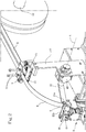
- the automatic feeder comprises an orientation assembly (10), structured to retain a free end (T) of a strip (R) on a predetermined gripping plane (11), in a waiting position.
- the strip (R) for example, is wound in a roll and the orientation assembly (10) retains the free end (T) in a desired position, useful for a grip of the end (T) itself by a gripping device that will be described in more detail below.
- the gripping plane (11) can be oriented horizontally or in another way. Preferably, the gripping plane (11) is horizontal.
- the orientation assembly (10) comprises at least one presser element (12), structured to press and retain the free end (T) of the strip (L) on the gripping plane (11).
- presser element (12) for example, is in the form of a pneumatic or hydraulic piston, activatable between an operating configuration, in which it presses and locks the free end (T) onto the gripping plane (11), and an active configuration, in which it does not interfere with the free end (T).
- the stem of the presser element (12) is movable vertically between the operating position and the inactive position.
- the orientation assembly (10) further comprises an abutment (13), structured to come into contact with a front edge of the free end (T) and to define the waiting position of the free end (T) on the gripping plane (11).
- the abutment (13) constitutes a reference for the correct positioning of the free end (T) on the gripping plane (11).
- the abutment (13) is movable between an operating position, in which it can come into contact with the front edge of the free end (T), and an inactive position, in which it does not interfere with the free end (T) and the strip (R) can slide longitudinally.
- the abutment (13) comprises an edge (14) being rotatable about an axis of rotation (X1) between the operating position and the inactive position.
- the edge (14) is solidly constrained to a support (15) being rotatable about the axis of rotation (X1).
- the support (15), in the operating position, is substantially aligned and coplanar with the gripping plane (11).
- the orientation assembly (10) comprises a detection means (16) provided to detect the correct location of the free end (T) in the gripping position on the gripping plane (11).
- detection means may for example be in the form of photocells or proximity sensors.
- the detection means (16) is positioned in proximity to the edge (14).
- the gripping plane (11), the presser element (12), the abutment (13) and the detection means (16) are associated with a support arm (17), which can be associated with the machine frame.
- the operation of the orientation assembly (10) can take place in the following ways. Initially the presser element (12) is in the inactive position and the abutment (13) is in the active position. The free end (T) can then be positioned on the gripping plane (11), bringing the end border into contact with the abutment (13), in particular in contact with the edge (14). Having reached that position, the presser element (12) is activated and is brought into the operating position, locking the free end (T) on the gripping plane. Subsequently, the abutment (13) is brought into the inactive position. The movements of the presser element (12) of the abutment (13) can be coordinated and driven by a control module, which receives the signal of the detection means (16) as an input.
- control module moves the presser element (12) into the operating position only after receiving the signal of the detection means (16) that indicates the correct positioning of the free end (T).
- the control module then drives the movement of the abutment (13) into the inactive position only after detecting the reaching of the operating position by the presser element (12).
- the automatic feeder comprises a support shaft (30) for supporting one or more rolls of strip (R).
- the number of rolls inserted side by side on the support shaft (30) substantially form the stock of strip (R) available for the automatic feeder.
- the automatic feeder further comprises one or more orientation assemblies (10), each of which is structured to retain a free end (T) of one of the strips (R) on a predetermined gripping plane (11), in a waiting position.
- the gripping planes (11) are coplanar to one another so that, in substance, there is a common gripping plane (11) for all the presser elements (12). In the waiting position, the free ends (T) of the various strips (R) are therefore arranged parallel to one another on the gripping plane (11).
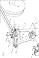
- the automatic feeder is further provided with a gripping device (20), structured to grasp the free end (T) of a strip (R) and to translate the end (T) from the waiting position to a feeding position, in which the end (T) can be grasped by another operating device (D).
- the operating device (D) comprises a cutting assembly (D), structured to grasp the free end (T) of a strip (R), for drawing in advancement the strip (R) and for cutting out from the strip (R) a plurality of sheets, which can subsequently be applied to a support disc by an assembly device.
- Both the cutting assembly (D) and the assembly device are known to a person skilled in the art and therefore will not be described in further detail.
- the gripping device (20) comprises a gripper (21), structured to grasp the free end (T) of a strip (R).
- the gripper comprises a fixed part (21a) and a movable part (21b) which can assume a gripping position, in which it is flanked to the fixed part and can lock the free end (T), and a release position, in which it is distanced from the fixed part and cannot lock the free end (T).
- a rotary actuator (M1) can be associated with the movable part (21b) to activate it in rotation between the gripping and release positions.
- the gripper (21) is associated with a support arm (22). Such support arm rotates about an axis of rotation (X) between a first position, in which the gripper (21) can grasp the free end (T) in the gripping position, and a second position, in which the free end (T), retained by the gripper (21), is brought into the proximity of the operating device (D) and can be picked up by it.
- An actuator device (M2) for example an electric or pneumatic motor, is provided to produce the rotation of the support arm (22).
- the actuator device (M2) is associated with the support arm (16) of the orientation assembly (10).
- the operation of the gripping device (20), and in particular of the gripper (21) and of the support arm (22), can be adjusted through the control module which acts on the orientation assembly (10).
- the gripper (21) and the arm (22) can be placed in an initial position in which the gripper (21) is in a release configuration and the support arm (22) in the first position.
- the control module detects the operating position of the presser element (12)
- the gripper (21) can be brought into the gripping configuration.
- the arm (22) is activated in rotation towards its second position, at which the free end (T) is grasped by the cutting assembly (D), or other operating device.
- the control module drives the opening of the gripper (21).
- the support shaft (30) and the orientation assemblies (10), or the orientation assembly (10) equipped with various presser elements (12), can translate so as to offer the free end (T) of a strip (R) to the gripping device.
- the support shaft (30) and the orientation assembly (10) can translate so as to align any of the free ends (T), in the respective waiting positions, with the first position of the gripper (21).
- one or more rolls of strip (R) can be inserted on the support shaft (30).
- the free ends (T) of each roll are associated with the orientation assembly (10), i.e. each free end (T) is locked on the gripping plane (11) by means of a respective presser element (12).
- the gripping element (20) moves to reach the free end (T) of a first roll of strip (R).
- the gripper (21) comes into the first position, with the movable part (21b) in the release position.
- the movable part (21b) is brought into the gripping position, squeezing the free end (T).
- the presser element (12) moves from the operating position to the inactive position, releasing the free end (T).
- the gripper (21) by means of the rotation of the support arm (22), draws the strip (R) in advancement and offers the free end (T) to the cutting assembly (D) which, in a known way, grasps the free end (T) and starts to gradually draw the strip (R) in advancement for subsequent processing.
- the support shaft (30) and the orientation assembly (10) translate and offer the free end (T) of a new strip (R) to the gripping device (20), which can then perform a new gripping and feeding cycle of the free end (T) in the ways described above.
- All the operations described above can obviously be coordinated by the control module already mentioned above.
- the control module can be configured to detect an empty roll and, in that condition, initiate the start of the steps described above for the replacement of the empty roll with another one.
- the automatic feeder according to the present invention achieves important advantages. It enables an empty roll of strip to be replaced in a totally automatic way, reducing the stopping times of the production cycle. If used in a machine for the production of abrasive discs, it allows the time required for changing an empty roll of strip to be drastically reduced, therefore allowing the machine's productivity to be improved, limiting the need for manual intervention by the operator and therefore the operating autonomy of the machine without the need for the constant supervision of an operator.
Landscapes
- Engineering & Computer Science (AREA)
- Mechanical Engineering (AREA)
- Finish Polishing, Edge Sharpening, And Grinding By Specific Grinding Devices (AREA)
- Automatic Assembly (AREA)
- Iron Core Of Rotating Electric Machines (AREA)
- Fluid-Driven Valves (AREA)
- Valve Device For Special Equipments (AREA)
- Replacement Of Web Rolls (AREA)
Claims (7)
- Automatische Zuführvorrichtung für einen Materialstreifen, dadurch gekennzeichnet, dass sie Folgendes umfasst:eine Ausrichtungsbaugruppe (10), die so strukturiert ist, dass sie ein freies Ende (T) eines Streifens (R) auf einer zuvor bestimmten Greiffläche (11) in einer Warteposition hält;eine Greifvorrichtung (20), die so strukturiert ist, dass sie das freie Ende (T) eines Streifens (R) fasst und das Ende (T) von der Warteposition in eine Zuführposition, in der das Ende (T) von einer anderen Bedienvorrichtung (D) fassbar ist, überführt;dadurch gekennzeichnet, dass die Ausrichtungsbaugruppe (10) mindestens ein Presselement (12), das so strukturiert ist, dass es das freie Ende (T) des Streifens (L) auf der Greiffläche (11) presst und hält, und einen Anschlag (13), der so strukturiert ist, dass er mit einer vorderen Kante des freien Endes (T) in Kontakt kommt und die Warteposition des freien Endes (T) auf der Greiffläche (11) definiert, umfasst.
- Automatische Zuführvorrichtung nach Anspruch 1, wobei der Anschlag (13) zwischen einer Bedienposition, in der er mit der vorderen Kante des freien Endes (T) in Kontakt kommen kann, um die Warteposition des freien Endes (T) auf der Greiffläche (11) zu definieren, und einer inaktiven Position, in der er nicht auf das freie Ende (T) einwirkt und der Streifen (R) in Längsrichtung im Raum gleiten kann, beweglich ist.
- Automatische Zuführvorrichtung nach Anspruch 2, wobei die Ausrichtungsbaugruppe (10) Erfassungseinrichtungen umfasst, die zum Erfassen der korrekten Lage des freien Endes (T) in der Greifposition auf der Greiffläche (11) ausgelegt sind.
- Automatische Zuführvorrichtung nach Anspruch 1, wobei die Greifvorrichtung (20) einen Greifer (21) umfasst, der so strukturiert ist, dass er das freie Ende (T) fasst.
- Automatische Zuführvorrichtung nach Anspruch 4, wobei der Greifer (21) mit einem Trägerarm (22) verbunden ist, der um eine Rotationsachse (X) zwischen einer ersten Position, in der der Greifer (21) das freie Ende (T) in der Greifposition fassen kann, und einer zweiten Position, in der das von dem Greifer (21) gehaltene freie Ende (T) von einer anderen Bedienvorrichtung (D) nehmbar ist, rotiert.
- Automatische Zuführvorrichtung nach Anspruch 1, umfassend: eine Trägerwelle (30) zum Tragen einer oder mehrerer Rollen von Streifen (R); eine oder mehrere Ausrichtungsbaugruppen (10), die jeweils so strukturiert sind, dass sie ein freies Ende (T) eines der Streifen (R) auf einer zuvor bestimmten Greiffläche (11) in einer Warteposition halten;
wobei die Greifvorrichtung (20) beweglich ist, um dazu fähig zu sein, das freie Ende (T) eines der Streifen (R) zu fassen und das Ende (T) von der Warteposition zu der Zuführposition, in der das Ende (T) von einer anderen Bedienvorrichtung (D) fassbar ist, zu überführen. - Maschine zur Herstellung von Schleifscheiben, umfassend: eine automatische Zuführvorrichtung (1) nach einem der vorangehenden Ansprüche; eine Schneidbaugruppe (D), die so strukturiert ist, dass sie das freie Ende (T) eines Streifens (R) fasst, um den Streifen (R) vorwärts zu ziehen und von dem Streifen (R) eine Vielzahl von Blättern abzuschneiden; eine Montagevorrichtung, die so strukturiert ist, dass sie die Blätter an einer Trägerscheibe befestigt.
Priority Applications (2)
| Application Number | Priority Date | Filing Date | Title |
|---|---|---|---|
| SI201730576T SI3312112T1 (sl) | 2016-10-14 | 2017-10-11 | Avtomatski podajalnik |
| PL17195979T PL3312112T3 (pl) | 2016-10-14 | 2017-10-11 | Podajnik automatyczny |
Applications Claiming Priority (1)
| Application Number | Priority Date | Filing Date | Title |
|---|---|---|---|
| IT102016000103467A IT201600103467A1 (it) | 2016-10-14 | 2016-10-14 | Alimentatore automatico |
Publications (2)
| Publication Number | Publication Date |
|---|---|
| EP3312112A1 EP3312112A1 (de) | 2018-04-25 |
| EP3312112B1 true EP3312112B1 (de) | 2020-12-02 |
Family
ID=58609682
Family Applications (1)
| Application Number | Title | Priority Date | Filing Date |
|---|---|---|---|
| EP17195979.4A Active EP3312112B1 (de) | 2016-10-14 | 2017-10-11 | Automatische zuführvorrichtung |
Country Status (6)
| Country | Link |
|---|---|
| US (1) | US20180105380A1 (de) |
| EP (1) | EP3312112B1 (de) |
| CN (1) | CN107954237A (de) |
| IT (1) | IT201600103467A1 (de) |
| PL (1) | PL3312112T3 (de) |
| SI (1) | SI3312112T1 (de) |
Families Citing this family (6)
| Publication number | Priority date | Publication date | Assignee | Title |
|---|---|---|---|---|
| JP6566084B1 (ja) | 2018-05-17 | 2019-08-28 | 横浜ゴム株式会社 | ゴムシート部材の供給装置および方法 |
| CN110091540B (zh) * | 2019-04-25 | 2021-04-23 | 许昌裕同印刷包装有限公司 | 一种高效自动点胶贴丝带系统 |
| CN111908220A (zh) * | 2020-09-21 | 2020-11-10 | 河南省新之林机电设备有限公司 | 带状物料加工用物料牵引装置 |
| JP7576380B2 (ja) * | 2021-04-15 | 2024-10-31 | エルジー エナジー ソリューション リミテッド | ロール形態の原料供給装置 |
| EP4347231B1 (de) | 2021-05-27 | 2025-10-15 | VMI Holland B.V. | Abwickelsystem und verfahren zum abwickeln einer reifenkomponente von einer vorratsrolle und zum ausgeben der reifenkomponente in eine transportrichtung |
| CN117923212B (zh) * | 2024-03-21 | 2024-06-04 | 宁波九纵智能科技有限公司 | 一种具有全自动上下料功能的reel盘芯片自动检测机 |
Family Cites Families (18)
| Publication number | Priority date | Publication date | Assignee | Title |
|---|---|---|---|---|
| US1570592A (en) * | 1925-03-10 | 1926-01-19 | Ohio Match Company | Sheet-feeding mechanism for forming machines |
| US1984804A (en) * | 1933-10-27 | 1934-12-18 | Int Cigar Mach Co | Registering web feed for wrapping machines |
| US2751981A (en) * | 1951-05-31 | 1956-06-26 | Armour & Co | Sheet forming and stacking apparatus |
| US2728950A (en) * | 1954-05-06 | 1956-01-03 | Dow Chemical Co | Process for producing fibers from films of polymeric materials |
| US3250152A (en) * | 1965-06-23 | 1966-05-10 | Kirby S Engineers Ltd | Method of and apparatus for creasing and/or cutting cardboard and analogous flexible sheet material |
| DE2417515C2 (de) * | 1974-04-10 | 1984-10-04 | Hauni-Werke Körber & Co KG, 2050 Hamburg | Vorrichtung zum Zuführen einer Hüllmaterialbahn zu einem Förderer in einer Zigarettenverpackungsmaschine |
| JPS60137749A (ja) * | 1983-12-27 | 1985-07-22 | Bridgestone Corp | 帯状部材の連査供給装置 |
| CA1263125A (en) * | 1984-06-01 | 1989-11-21 | Hans-Guenter E. Kuehnert | Apparatus for the automatic feeding of a laminating station |
| US4646986A (en) * | 1984-11-22 | 1987-03-03 | Hauni-Werke Korber & Co. Kg | Apparatus for locating, engaging and transporting the leader of convoluted cigarette paper or the like |
| US4793229A (en) * | 1986-12-24 | 1988-12-27 | Western Printing Machinery Company | Multifunctional web rotary module |
| DE69729693T2 (de) * | 1996-07-17 | 2004-10-21 | Fuji Photo Film Co Ltd | Vorbereitungsverfahren und -apparat zum Verbinden von Bahnen |
| DE10057597A1 (de) * | 2000-11-21 | 2002-05-23 | Kolbus Gmbh & Co Kg | Vorrichtung zum Speichern und Abwickeln von Materialrollen in Buchbindereimaschinen |
| WO2007122725A1 (ja) * | 2006-04-21 | 2007-11-01 | Toyo Tire & Rubber Co., Ltd. | 帯状材料の接続方法及び装置 |
| JP2010126313A (ja) * | 2008-11-27 | 2010-06-10 | Mitsubishi Heavy Ind Ltd | 折機並びに印刷機及び印刷方法 |
| EP2258643B1 (de) * | 2009-06-01 | 2015-01-14 | Tetra Laval Holdings & Finance S.A. | Verfahren zur Beschickung einer Versorgungsstation einer Verpackungseinheit mit einer neuen Rolle aus Blattverpackungsmaterial, Blattverpackungsmaterialhalter und Gabelstapler |
| ITFI20110253A1 (it) * | 2011-11-23 | 2013-05-24 | Perini Fabio Spa | "svolgitore per bobine e metodo di svolgimento" |
| DE102013204956A1 (de) * | 2013-03-20 | 2014-09-25 | Gea Food Solutions Germany Gmbh | Abrollvorrichtung für eine Interleaverrolle sowie System bestehen aus einerAufschneidevorrichtung und der Abrollvorrichtung |
| EP2797182B1 (de) * | 2013-04-24 | 2020-06-17 | Komax Holding AG | Kabelkonfektioniervorrichtung zum Ablängen, Abisolieren und Konfektionieren eines Kabels mit Crimpkontakten |
-
2016
- 2016-10-14 IT IT102016000103467A patent/IT201600103467A1/it unknown
-
2017
- 2017-10-11 EP EP17195979.4A patent/EP3312112B1/de active Active
- 2017-10-11 SI SI201730576T patent/SI3312112T1/sl unknown
- 2017-10-11 PL PL17195979T patent/PL3312112T3/pl unknown
- 2017-10-13 US US15/783,341 patent/US20180105380A1/en not_active Abandoned
- 2017-10-16 CN CN201710958607.4A patent/CN107954237A/zh active Pending
Non-Patent Citations (1)
| Title |
|---|
| None * |
Also Published As
| Publication number | Publication date |
|---|---|
| SI3312112T1 (sl) | 2021-03-31 |
| CN107954237A (zh) | 2018-04-24 |
| US20180105380A1 (en) | 2018-04-19 |
| EP3312112A1 (de) | 2018-04-25 |
| PL3312112T3 (pl) | 2021-05-17 |
| IT201600103467A1 (it) | 2018-04-14 |
Similar Documents
| Publication | Publication Date | Title |
|---|---|---|
| EP3312112B1 (de) | Automatische zuführvorrichtung | |
| US8210079B2 (en) | Programmable border slitter | |
| US8740128B2 (en) | Winder assembly and method of use thereof | |
| JP6101546B2 (ja) | 裁断装置 | |
| JP6635344B2 (ja) | 紙、段ボール、プラスチック材、複合材又はその種の比較的堅固な材料を切断するための切断装置 | |
| US7621479B2 (en) | Supply-roll switching apparatus | |
| CN105751554B (zh) | 用于对接发粘的带件的拼接装置 | |
| EP3436224B1 (de) | Vorrichtung und verfahren zur umwandelung eines blattes in einen durchgehenden streifen | |
| US5456098A (en) | Process and apparatus for controlling the loading of a processing machine with band-like material | |
| CN112978487A (zh) | 医用生产线卷料循环收集装置 | |
| EP3395736B1 (de) | Rollenzuführvorrichtung | |
| CN210236658U (zh) | 印刷机的分条装置 | |
| CN107696147A (zh) | 一种商标裁切装置 | |
| EP3088169B1 (de) | Auslasskordbefestigungsvorrichtung und befestigungsverfahren | |
| EP2911838B1 (de) | Vorrichtung und verfahren zum abtragen einer mehrschichtigen bahn mit einer trageschicht und mindestens einem mit der trageschicht gekoppelten haftfilm | |
| CN110394845B (zh) | 一种压痕自动拉料机 | |
| US20040088952A1 (en) | Apparatus for perforating a packing film | |
| JP7774618B2 (ja) | 材料片を機械ツールの機械加工ゾーンに給送する方法 | |
| JP3571879B2 (ja) | リードフレーム間紙挿入装置 | |
| JP2647536B2 (ja) | 粘着テープ貼付装置 | |
| US4020727A (en) | Automatic capacitor winding machine | |
| KR20170032270A (ko) | 코드 밴드 절단용 슬리터 | |
| WO2000056495A1 (en) | A method and apparatus for the handling of metal scrap | |
| ITMI20081437A1 (it) | Macchina perfezionata atta ad eseguire il taglio, la punzonatura e la roditura di lamiere. | |
| AU3263900A (en) | A method and apparatus for the handling of metal scrap |
Legal Events
| Date | Code | Title | Description |
|---|---|---|---|
| PUAI | Public reference made under article 153(3) epc to a published international application that has entered the european phase |
Free format text: ORIGINAL CODE: 0009012 |
|
| STAA | Information on the status of an ep patent application or granted ep patent |
Free format text: STATUS: THE APPLICATION HAS BEEN PUBLISHED |
|
| AK | Designated contracting states |
Kind code of ref document: A1 Designated state(s): AL AT BE BG CH CY CZ DE DK EE ES FI FR GB GR HR HU IE IS IT LI LT LU LV MC MK MT NL NO PL PT RO RS SE SI SK SM TR |
|
| AX | Request for extension of the european patent |
Extension state: BA ME |
|
| STAA | Information on the status of an ep patent application or granted ep patent |
Free format text: STATUS: REQUEST FOR EXAMINATION WAS MADE |
|
| 17P | Request for examination filed |
Effective date: 20181002 |
|
| RBV | Designated contracting states (corrected) |
Designated state(s): AL AT BE BG CH CY CZ DE DK EE ES FI FR GB GR HR HU IE IS IT LI LT LU LV MC MK MT NL NO PL PT RO RS SE SI SK SM TR |
|
| REG | Reference to a national code |
Ref country code: DE Ref legal event code: R079 Ref document number: 602017028676 Country of ref document: DE Free format text: PREVIOUS MAIN CLASS: B65H0019180000 Ipc: B24D0011000000 |
|
| RIC1 | Information provided on ipc code assigned before grant |
Ipc: B24D 11/00 20060101AFI20200330BHEP Ipc: B65H 19/18 20060101ALI20200330BHEP |
|
| GRAP | Despatch of communication of intention to grant a patent |
Free format text: ORIGINAL CODE: EPIDOSNIGR1 |
|
| STAA | Information on the status of an ep patent application or granted ep patent |
Free format text: STATUS: GRANT OF PATENT IS INTENDED |
|
| INTG | Intention to grant announced |
Effective date: 20200527 |
|
| GRAS | Grant fee paid |
Free format text: ORIGINAL CODE: EPIDOSNIGR3 |
|
| GRAA | (expected) grant |
Free format text: ORIGINAL CODE: 0009210 |
|
| STAA | Information on the status of an ep patent application or granted ep patent |
Free format text: STATUS: THE PATENT HAS BEEN GRANTED |
|
| AK | Designated contracting states |
Kind code of ref document: B1 Designated state(s): AL AT BE BG CH CY CZ DE DK EE ES FI FR GB GR HR HU IE IS IT LI LT LU LV MC MK MT NL NO PL PT RO RS SE SI SK SM TR |
|
| REG | Reference to a national code |
Ref country code: GB Ref legal event code: FG4D |
|
| REG | Reference to a national code |
Ref country code: AT Ref legal event code: REF Ref document number: 1340377 Country of ref document: AT Kind code of ref document: T Effective date: 20201215 Ref country code: CH Ref legal event code: EP |
|
| REG | Reference to a national code |
Ref country code: IE Ref legal event code: FG4D |
|
| REG | Reference to a national code |
Ref country code: DE Ref legal event code: R096 Ref document number: 602017028676 Country of ref document: DE |
|
| REG | Reference to a national code |
Ref country code: NL Ref legal event code: FP |
|
| PG25 | Lapsed in a contracting state [announced via postgrant information from national office to epo] |
Ref country code: GR Free format text: LAPSE BECAUSE OF FAILURE TO SUBMIT A TRANSLATION OF THE DESCRIPTION OR TO PAY THE FEE WITHIN THE PRESCRIBED TIME-LIMIT Effective date: 20210303 Ref country code: FI Free format text: LAPSE BECAUSE OF FAILURE TO SUBMIT A TRANSLATION OF THE DESCRIPTION OR TO PAY THE FEE WITHIN THE PRESCRIBED TIME-LIMIT Effective date: 20201202 Ref country code: NO Free format text: LAPSE BECAUSE OF FAILURE TO SUBMIT A TRANSLATION OF THE DESCRIPTION OR TO PAY THE FEE WITHIN THE PRESCRIBED TIME-LIMIT Effective date: 20210302 Ref country code: RS Free format text: LAPSE BECAUSE OF FAILURE TO SUBMIT A TRANSLATION OF THE DESCRIPTION OR TO PAY THE FEE WITHIN THE PRESCRIBED TIME-LIMIT Effective date: 20201202 |
|
| REG | Reference to a national code |
Ref country code: AT Ref legal event code: MK05 Ref document number: 1340377 Country of ref document: AT Kind code of ref document: T Effective date: 20201202 |
|
| PG25 | Lapsed in a contracting state [announced via postgrant information from national office to epo] |
Ref country code: SE Free format text: LAPSE BECAUSE OF FAILURE TO SUBMIT A TRANSLATION OF THE DESCRIPTION OR TO PAY THE FEE WITHIN THE PRESCRIBED TIME-LIMIT Effective date: 20201202 Ref country code: BG Free format text: LAPSE BECAUSE OF FAILURE TO SUBMIT A TRANSLATION OF THE DESCRIPTION OR TO PAY THE FEE WITHIN THE PRESCRIBED TIME-LIMIT Effective date: 20210302 Ref country code: LV Free format text: LAPSE BECAUSE OF FAILURE TO SUBMIT A TRANSLATION OF THE DESCRIPTION OR TO PAY THE FEE WITHIN THE PRESCRIBED TIME-LIMIT Effective date: 20201202 |
|
| PG25 | Lapsed in a contracting state [announced via postgrant information from national office to epo] |
Ref country code: HR Free format text: LAPSE BECAUSE OF FAILURE TO SUBMIT A TRANSLATION OF THE DESCRIPTION OR TO PAY THE FEE WITHIN THE PRESCRIBED TIME-LIMIT Effective date: 20201202 |
|
| REG | Reference to a national code |
Ref country code: LT Ref legal event code: MG9D |
|
| PG25 | Lapsed in a contracting state [announced via postgrant information from national office to epo] |
Ref country code: SK Free format text: LAPSE BECAUSE OF FAILURE TO SUBMIT A TRANSLATION OF THE DESCRIPTION OR TO PAY THE FEE WITHIN THE PRESCRIBED TIME-LIMIT Effective date: 20201202 Ref country code: PT Free format text: LAPSE BECAUSE OF FAILURE TO SUBMIT A TRANSLATION OF THE DESCRIPTION OR TO PAY THE FEE WITHIN THE PRESCRIBED TIME-LIMIT Effective date: 20210405 Ref country code: RO Free format text: LAPSE BECAUSE OF FAILURE TO SUBMIT A TRANSLATION OF THE DESCRIPTION OR TO PAY THE FEE WITHIN THE PRESCRIBED TIME-LIMIT Effective date: 20201202 Ref country code: SM Free format text: LAPSE BECAUSE OF FAILURE TO SUBMIT A TRANSLATION OF THE DESCRIPTION OR TO PAY THE FEE WITHIN THE PRESCRIBED TIME-LIMIT Effective date: 20201202 Ref country code: LT Free format text: LAPSE BECAUSE OF FAILURE TO SUBMIT A TRANSLATION OF THE DESCRIPTION OR TO PAY THE FEE WITHIN THE PRESCRIBED TIME-LIMIT Effective date: 20201202 Ref country code: EE Free format text: LAPSE BECAUSE OF FAILURE TO SUBMIT A TRANSLATION OF THE DESCRIPTION OR TO PAY THE FEE WITHIN THE PRESCRIBED TIME-LIMIT Effective date: 20201202 Ref country code: CZ Free format text: LAPSE BECAUSE OF FAILURE TO SUBMIT A TRANSLATION OF THE DESCRIPTION OR TO PAY THE FEE WITHIN THE PRESCRIBED TIME-LIMIT Effective date: 20201202 |
|
| PG25 | Lapsed in a contracting state [announced via postgrant information from national office to epo] |
Ref country code: AT Free format text: LAPSE BECAUSE OF FAILURE TO SUBMIT A TRANSLATION OF THE DESCRIPTION OR TO PAY THE FEE WITHIN THE PRESCRIBED TIME-LIMIT Effective date: 20201202 |
|
| REG | Reference to a national code |
Ref country code: DE Ref legal event code: R097 Ref document number: 602017028676 Country of ref document: DE |
|
| PG25 | Lapsed in a contracting state [announced via postgrant information from national office to epo] |
Ref country code: IS Free format text: LAPSE BECAUSE OF FAILURE TO SUBMIT A TRANSLATION OF THE DESCRIPTION OR TO PAY THE FEE WITHIN THE PRESCRIBED TIME-LIMIT Effective date: 20210402 |
|
| PLBE | No opposition filed within time limit |
Free format text: ORIGINAL CODE: 0009261 |
|
| STAA | Information on the status of an ep patent application or granted ep patent |
Free format text: STATUS: NO OPPOSITION FILED WITHIN TIME LIMIT |
|
| PG25 | Lapsed in a contracting state [announced via postgrant information from national office to epo] |
Ref country code: AL Free format text: LAPSE BECAUSE OF FAILURE TO SUBMIT A TRANSLATION OF THE DESCRIPTION OR TO PAY THE FEE WITHIN THE PRESCRIBED TIME-LIMIT Effective date: 20201202 |
|
| 26N | No opposition filed |
Effective date: 20210903 |
|
| PG25 | Lapsed in a contracting state [announced via postgrant information from national office to epo] |
Ref country code: DK Free format text: LAPSE BECAUSE OF FAILURE TO SUBMIT A TRANSLATION OF THE DESCRIPTION OR TO PAY THE FEE WITHIN THE PRESCRIBED TIME-LIMIT Effective date: 20201202 |
|
| PG25 | Lapsed in a contracting state [announced via postgrant information from national office to epo] |
Ref country code: ES Free format text: LAPSE BECAUSE OF FAILURE TO SUBMIT A TRANSLATION OF THE DESCRIPTION OR TO PAY THE FEE WITHIN THE PRESCRIBED TIME-LIMIT Effective date: 20201202 |
|
| REG | Reference to a national code |
Ref country code: CH Ref legal event code: PL |
|
| PG25 | Lapsed in a contracting state [announced via postgrant information from national office to epo] |
Ref country code: IS Free format text: LAPSE BECAUSE OF FAILURE TO SUBMIT A TRANSLATION OF THE DESCRIPTION OR TO PAY THE FEE WITHIN THE PRESCRIBED TIME-LIMIT Effective date: 20210402 |
|
| REG | Reference to a national code |
Ref country code: BE Ref legal event code: MM Effective date: 20211031 |
|
| PG25 | Lapsed in a contracting state [announced via postgrant information from national office to epo] |
Ref country code: MC Free format text: LAPSE BECAUSE OF FAILURE TO SUBMIT A TRANSLATION OF THE DESCRIPTION OR TO PAY THE FEE WITHIN THE PRESCRIBED TIME-LIMIT Effective date: 20201202 |
|
| PG25 | Lapsed in a contracting state [announced via postgrant information from national office to epo] |
Ref country code: LU Free format text: LAPSE BECAUSE OF NON-PAYMENT OF DUE FEES Effective date: 20211011 Ref country code: BE Free format text: LAPSE BECAUSE OF NON-PAYMENT OF DUE FEES Effective date: 20211031 |
|
| PG25 | Lapsed in a contracting state [announced via postgrant information from national office to epo] |
Ref country code: LI Free format text: LAPSE BECAUSE OF NON-PAYMENT OF DUE FEES Effective date: 20211031 Ref country code: CH Free format text: LAPSE BECAUSE OF NON-PAYMENT OF DUE FEES Effective date: 20211031 |
|
| PG25 | Lapsed in a contracting state [announced via postgrant information from national office to epo] |
Ref country code: IE Free format text: LAPSE BECAUSE OF NON-PAYMENT OF DUE FEES Effective date: 20211011 |
|
| PG25 | Lapsed in a contracting state [announced via postgrant information from national office to epo] |
Ref country code: HU Free format text: LAPSE BECAUSE OF FAILURE TO SUBMIT A TRANSLATION OF THE DESCRIPTION OR TO PAY THE FEE WITHIN THE PRESCRIBED TIME-LIMIT; INVALID AB INITIO Effective date: 20171011 |
|
| PG25 | Lapsed in a contracting state [announced via postgrant information from national office to epo] |
Ref country code: CY Free format text: LAPSE BECAUSE OF FAILURE TO SUBMIT A TRANSLATION OF THE DESCRIPTION OR TO PAY THE FEE WITHIN THE PRESCRIBED TIME-LIMIT Effective date: 20201202 |
|
| P01 | Opt-out of the competence of the unified patent court (upc) registered |
Effective date: 20230601 |
|
| PG25 | Lapsed in a contracting state [announced via postgrant information from national office to epo] |
Ref country code: MK Free format text: LAPSE BECAUSE OF FAILURE TO SUBMIT A TRANSLATION OF THE DESCRIPTION OR TO PAY THE FEE WITHIN THE PRESCRIBED TIME-LIMIT Effective date: 20201202 |
|
| PG25 | Lapsed in a contracting state [announced via postgrant information from national office to epo] |
Ref country code: MT Free format text: LAPSE BECAUSE OF FAILURE TO SUBMIT A TRANSLATION OF THE DESCRIPTION OR TO PAY THE FEE WITHIN THE PRESCRIBED TIME-LIMIT Effective date: 20201202 |
|
| PGFP | Annual fee paid to national office [announced via postgrant information from national office to epo] |
Ref country code: PL Payment date: 20250923 Year of fee payment: 9 Ref country code: TR Payment date: 20250923 Year of fee payment: 9 |
|
| PGFP | Annual fee paid to national office [announced via postgrant information from national office to epo] |
Ref country code: SI Payment date: 20250922 Year of fee payment: 9 |
|
| PGFP | Annual fee paid to national office [announced via postgrant information from national office to epo] |
Ref country code: NL Payment date: 20251024 Year of fee payment: 9 |
|
| PGFP | Annual fee paid to national office [announced via postgrant information from national office to epo] |
Ref country code: DE Payment date: 20251028 Year of fee payment: 9 |
|
| PGFP | Annual fee paid to national office [announced via postgrant information from national office to epo] |
Ref country code: GB Payment date: 20251023 Year of fee payment: 9 |
|
| PGFP | Annual fee paid to national office [announced via postgrant information from national office to epo] |
Ref country code: IT Payment date: 20251007 Year of fee payment: 9 |
|
| PGFP | Annual fee paid to national office [announced via postgrant information from national office to epo] |
Ref country code: FR Payment date: 20251027 Year of fee payment: 9 |