EP3312053B1 - Assembly for attaching a limiter for the travel of a rear shelf on the rear door of a motor vehicle - Google Patents
Assembly for attaching a limiter for the travel of a rear shelf on the rear door of a motor vehicle Download PDFInfo
- Publication number
- EP3312053B1 EP3312053B1 EP17191954.1A EP17191954A EP3312053B1 EP 3312053 B1 EP3312053 B1 EP 3312053B1 EP 17191954 A EP17191954 A EP 17191954A EP 3312053 B1 EP3312053 B1 EP 3312053B1
- Authority
- EP
- European Patent Office
- Prior art keywords
- base
- assembly
- head
- door
- radius
- Prior art date
- Legal status (The legal status is an assumption and is not a legal conclusion. Google has not performed a legal analysis and makes no representation as to the accuracy of the status listed.)
- Active
Links
- 239000007787 solid Substances 0.000 claims description 6
- 230000002093 peripheral effect Effects 0.000 claims description 2
- 238000004873 anchoring Methods 0.000 description 2
- 230000005489 elastic deformation Effects 0.000 description 2
- 239000000463 material Substances 0.000 description 2
- 208000019300 CLIPPERS Diseases 0.000 description 1
- 101001017827 Mus musculus Leucine-rich repeat flightless-interacting protein 1 Proteins 0.000 description 1
- 230000003042 antagnostic effect Effects 0.000 description 1
- 208000021930 chronic lymphocytic inflammation with pontine perivascular enhancement responsive to steroids Diseases 0.000 description 1
- 239000002131 composite material Substances 0.000 description 1
- 230000000694 effects Effects 0.000 description 1
- 238000012423 maintenance Methods 0.000 description 1
- 239000002184 metal Substances 0.000 description 1
- 238000012856 packing Methods 0.000 description 1
- 239000004033 plastic Substances 0.000 description 1
Images

Classifications
-
- B—PERFORMING OPERATIONS; TRANSPORTING
- B60—VEHICLES IN GENERAL
- B60R—VEHICLES, VEHICLE FITTINGS, OR VEHICLE PARTS, NOT OTHERWISE PROVIDED FOR
- B60R5/00—Compartments within vehicle body primarily intended or sufficiently spacious for trunks, suit-cases, or the like
- B60R5/04—Compartments within vehicle body primarily intended or sufficiently spacious for trunks, suit-cases, or the like arranged at rear of vehicle
- B60R5/044—Compartments within vehicle body primarily intended or sufficiently spacious for trunks, suit-cases, or the like arranged at rear of vehicle luggage covering means, e.g. parcel shelves
-
- B—PERFORMING OPERATIONS; TRANSPORTING
- B60—VEHICLES IN GENERAL
- B60R—VEHICLES, VEHICLE FITTINGS, OR VEHICLE PARTS, NOT OTHERWISE PROVIDED FOR
- B60R5/00—Compartments within vehicle body primarily intended or sufficiently spacious for trunks, suit-cases, or the like
- B60R5/04—Compartments within vehicle body primarily intended or sufficiently spacious for trunks, suit-cases, or the like arranged at rear of vehicle
Definitions
- the present invention relates to the rear shelves of motor vehicles which are retractable storage shelves fitted to the rear parts of certain motor vehicles.
- It relates more particularly to a set of fixing a travel limiter of a rear shelf on the rear door of a vehicle.
- the document DE 20 2009 004 736 U1 discloses a fixing assembly of a travel limit limiter of a rear shelf of a motor vehicle according to the preamble of claim 1.
- a rear shelf 1 of a motor vehicle is rotatably mounted relative to the body structure (not shown) of the vehicle.
- the tablet 1 is provided with one or two flexible cords 2 (only one cord is shown on the figure 1 ), also called travel limiters, a first end 3 is secured to the tablet 1 and a second end 4, free, can be provided with a loop 5 ( Fig. 3 ) to removably fix the cord 2 the tailgate, also called the rear flap 6 ( Fig. 2 ).
- the shelf 1 is arranged in such a way that when the rear door 6 is rotated, for the opening of the trunk, the shelf 1 is also rotated by means of the travel limiters 2.
- the loop 5 is able to be threaded removably onto a base 7 integral with the inner lining 8 of the flap 6.
- the projecting portion of the base 7, or head 9, defines a flange 10 with rounded edges.
- the base 7 further comprises a groove 11 adapted to receive the loop 5.
- the loop 5 can be replaced by a tip 12 secured to the end 10B of the limiter 2 and which is adapted to be clipped onto the head 9 of the base 7.
- the tip 12 has a cavity 13 delimited by antagonistic deformable tabs 14, integral with the tip 12, and whose ends terminate in stops.
- the tabs 14 move apart when the nozzle 12 is pressed on the head 9 by elastic deformation of the tabs 14 and, with the head 9 passed, the ends of the tabs 14 provided with the stops are tightened behind the head 9 in the groove 11 formed behind the head 9 of the base 7 ensuring the removable attachment of the nozzle assembly 12 / base 7.
- a tip 12 clipped on the base 7 is more immediate than the threading of a loop 5.
- the tip 12 must respect an offset angle ⁇ sufficient to accompany the rotation of the flap 1 without risk unclipping the nozzle 12.
- the axis of rotation of the tablet is parallel to the axis passing through the hinges solidarisant rotation the flap on the rear upper part of the vehicle body.
- the maximum offset angle ⁇ of the tip on the base is limited to 5 °. This angle ⁇ may not be insufficient for arrangements of shelf 1 / rear flap 6 requiring high deflections (offset angle ⁇ greater than 5 °); an offset angle ⁇ insufficient that can lead to inadvertent declipping of the tip 12.
- the force required to unclip the tip 12 of the head 9 may be conducive to tearing the base 7 fixed directly to the lining 8 of the flap 6.
- the object of the present invention is to provide an attachment assembly for accepting a larger angle offset between the tip and the base.
- This solution provides more freedom in the positioning of the base to take into account the difference in stretching of the cord between the positions of the closed or open shelf for which there can be a delta of 150% of the length of the cord .
- the present invention provides a gain in terms of transversality since it can adapt to several vehicle models (high end or low end).
- Fixing the base also has the advantage of keeping the lining robustly on the flap.
- the cord remains tight throughout the opening and closing kinematics of the shutter. What avoids having a cordon that has the state of closure of the shutter hangs in part on the shelf which can affect the aesthetic effect.
- the subject of the invention is an assembly for attaching a travel limiter of a rear shelf of a motor vehicle to the rear door of said vehicle, said limiter being provided with at least one cord, a first end is secured to the rear shelf and a second end of which is provided with a first fastening element capable of being releasably secured to a base secured to the flap, characterized in that the body of the base comprises a head forming a solid spherical cap adapted to receive the first fastening element and a fastening interface adapted to secure the base on the shutter.
- the cap has a specific height and radius; the height of the cap being greater than its radius.
- the fixing interface delimits with the head of the base a groove of determined width, adapted to receive the first fastening element.
- the first fastening element is a loop capable of being threaded between the head and the interface for fixing the base inside the groove.
- the attachment interface defines a flange having a groove oriented towards the groove ensuring the centering of the loop in the groove.
- the first fastening element is a tip adapted to be clipped onto the head of the base.
- the tip comprises a cavity forming a hollow spherical cap of the same radius as the full spherical cap of the base; the depth of the cavity being greater than its radius and the depth of the cavity being between the radius and the height of the solid spherical cap.
- the cavity is delimited by a peripheral edge of determined thickness formed by at least two elastically deformable tabs disposed opposite one another.
- the maximum offset angle of the tip on the base is less than or equal to 20 ° between two extreme positions of the tip on the base.
- the base is secured to the flap by means of a screw passing right through the body of the base and the trim portion of the rear flap; said screw holding the body of the base and the trim part on the flap.
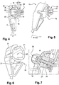
- FIG 4 there is shown an attachment assembly according to the invention, in section, having a nozzle 15 and a base 16 in an assembly position.
- the base 16 has a head 17 in the form of a solid spherical cap capable of cooperating with the tip 15.
- the cap 17 has a height H and a determined radius R: the height H of the head 17 being greater than its radius R.
- the base of the spherical cap 17 delimits with the attachment interface 18 of the base 16, in the form of a flange, a groove 19 of determined width l.
- This groove 19 can be advantageously used to insert a loop such as the loop 5 of the figure 3 .
- the base 16 can serve both for a clipper tip 15 for a loop to thread 5.
- the periphery of the collar is advantageously chamfered to allow self centering of the loop 5 inside the groove 19 ; the base 16 by its general form can be likened to a "diabolo".
- the tip 15 has a hollow spherical cap 20 forming a cavity 20 adapted to receive a portion of the head 17 of the base 16.
- the depth P of the cavity 20 is greater than its radius R.
- the rays R of the cavity 20 and the head 17 are identical.
- the depth P of the cavity 20 is between the radius R height H of the head 17 (R ⁇ P ⁇ H).
- the wall or edge of the nozzle 15 delimiting the cavity 20 is shaped to have three lugs 21 distributed facing each other at 180 ° C. one of the others and which are capable of deforming during the introduction of the tip 15 on the base 16.
- the controlled elastic deformation of the tabs 21, allows sufficient pressure to maintain the ball-type connection between the tip 15 and the base 16.
- the fixing assembly as described above allows a wide variety of possible configurations in the positioning of the base 16 on different types of flaps 6 as well as metal or plastic or composite material, with deflections of the flap 6 and of the tablet 1 for which the tip 15 can accept a maximum offset angle ⁇ max of 20 ° on all degrees of freedom offered by the ball-type connection with the base 16.
- the attachment interface 18 of the base comprises anchoring means 22 able to fix the base 16 on a support such as the interior lining 8 of the flap 6.
- the anchoring means 22 as illustrated comprise three or four tabs or fastening clips 23 integral with the body of the base 16 and cooperating with openings (not shown) in the packing 8.
- the body of the base 16 is traversed along its longitudinal axis by a bore 24 adapted to receive a screw 25.
- the head 17 of the base 16 has a recess 26 centered on the same longitudinal axis and adapted to receive the head of the screw 25 which is embedded in the recess 26.
- the threaded portion of the screw 25 passes right through the body of the base 16, the gasket 8 and a portion of the flap 6.
- the screw head 25 abuts in the recess 26.
- the end of the threaded portion opposed to the screw head, protruding from the portion of the flap 6, is adapted to receive a nut (not shown) so as to ensure the clamping of the stack constituted by the body of the base 16 and the trim portion 8 interposed between the flap 6 and the base 16, and therefore the secure attachment of the base 16 on the flap 6 preventing tearing of the base 16 of the lining 8 at the time of unclipping the tip 15 of the head 17 of the base 16.
- the nut may be replaced by a threaded boss (not shown), for example integral with the material of the flap 6 or attached to the material of the flap 6.
- the flexible cord 2 can be extensible or inextensible longitudinally but the fixing assembly according to the invention makes it possible to keep the cord 2 taut at the beginning and the end of the kinematics of the flap 6.
Landscapes
- Engineering & Computer Science (AREA)
- Mechanical Engineering (AREA)
- Vehicle Step Arrangements And Article Storage (AREA)
- Vehicle Interior And Exterior Ornaments, Soundproofing, And Insulation (AREA)
- Power-Operated Mechanisms For Wings (AREA)
- Fittings On The Vehicle Exterior For Carrying Loads, And Devices For Holding Or Mounting Articles (AREA)
Description
La présente invention concerne les tablettes arrière des véhicules automobiles qui sont des tablettes de rangement escamotables équipant les parties arrière de certains véhicules automobiles.The present invention relates to the rear shelves of motor vehicles which are retractable storage shelves fitted to the rear parts of certain motor vehicles.
Elle concerne plus particulièrement un ensemble de fixation d'un limiteur de débattement d'une tablette arrière sur le volet arrière d'un véhicule.It relates more particularly to a set of fixing a travel limiter of a rear shelf on the rear door of a vehicle.
Le document
Classiquement, tel qu'illustré sur les
La tablette 1 est agencée de telle manière que lorsque le volet arrière 6 est entraîné en rotation, pour l'ouverture du coffre, la tablette1 est également entraînée en rotation par le biais des limiteurs de débattement 2.The
La boucle 5 est apte à être enfilée de manière amovible sur une embase 7 solidaire de la garniture intérieure 8 du volet 6.The
La partie en saillie de l'embase 7, ou tête 9, définit une collerette 10 à bords arrondis. L'embase 7 comporte en outre une gorge 11 apte à recevoir la boucle 5. La boucle 5 peut être remplacée par un embout 12 solidaire de l'extrémité 10B du limiteur 2 et qui est apte à être clippé sur la tête 9 de l'embase 7.The projecting portion of the
L'embout 12 comporte une cavité 13 délimitée par des pattes déformables antagonistes 14, venues de matière avec l'embout 12, et dont les extrémités se terminent par des butées. Les pattes 14 s'écartent quand l'embout 12 est enfoncé sur la tête 9 par déformation élastique des pattes 14 puis, la tête 9 passée, les extrémités des pattes 14 munies des butées se resserrent derrière la tête 9 dans la gorge 11 ménagée derrière la tête 9 de l'embase 7 assurant la fixation amovible de l'ensemble embout 12 /embase 7.The
L'utilisation d'un embout 12 clippé sur l'embase 7 est plus immédiate que l'enfilement d'une boucle 5. Toutefois, l'embout 12 doit respecter un angle de décalage θ suffisant pour accompagner la rotation du volet 1 sans risque de déclippage de l'embout 12.The use of a
L'axe de rotation de la tablette est parallèle à l'axe passant par les charnières solidarisant à rotation le volet sur la partie haute arrière de la carrosserie du véhicule.The axis of rotation of the tablet is parallel to the axis passing through the hinges solidarisant rotation the flap on the rear upper part of the vehicle body.
Dans l'exemple décrit, l'angle de décalage maximum θ de l'embout sur l'embase est limité à 5°. Cet angle θ peut ne pas être est insuffisant pour des agencements de tablette 1 /volet 6 arrière nécessitant de forts débattements (angle de décalage θ supérieur à 5°) ; un angle de décalage θ insuffisant pouvant entrainer un déclippage intempestif de l'embout 12.In the example described, the maximum offset angle θ of the tip on the base is limited to 5 °. This angle θ may not be insufficient for arrangements of
D'autre part, la force nécessaire pour déclipper l'embout 12 de la tête 9 peut être propice à un arrachement de l'embase 7 fixée directement sur la garniture 8 du volet 6.On the other hand, the force required to unclip the
Le but de la présente invention est de proposer un ensemble de fixation permettant d'accepter un plus grand décalage d'angle entre l'embout et l'embase. Cette solution apporte plus de liberté dans le positionnement de l'embase permettant de tenir compte de la différence d'étirement du cordon entre les positions de la tablette fermée où ouverte pour lesquels il peut y avoir un delta de 150% de la longueur du cordon.The object of the present invention is to provide an attachment assembly for accepting a larger angle offset between the tip and the base. This solution provides more freedom in the positioning of the base to take into account the difference in stretching of the cord between the positions of the closed or open shelf for which there can be a delta of 150% of the length of the cord .
La présente invention apporte un gain en termes de transversalité puisqu'elle peut s'adapter à plusieurs modèles de véhicule (haut de gamme ou bas de gamme).The present invention provides a gain in terms of transversality since it can adapt to several vehicle models (high end or low end).
La fixation de l'embase a également pour avantage de tenir la garniture de manière robuste sur le volet.Fixing the base also has the advantage of keeping the lining robustly on the flap.
Le cordon reste tendu dans toute la cinématique d'ouverture et de fermeture du volet. Ce qui évite d'avoir un cordon qui a l'état de fermeture du volet pend en partie sur la tablette ce qui peut nuire à l'effet esthétique.The cord remains tight throughout the opening and closing kinematics of the shutter. What avoids having a cordon that has the state of closure of the shutter hangs in part on the shelf which can affect the aesthetic effect.
A cet effet, l'invention a pour objet un ensemble de fixation d'un limiteur de débattement d'une tablette arrière d'un véhicule automobile sur le volet arrière dudit véhicule, ledit limiteur étant muni d'au moins un cordon dont une première extrémité est solidarisée à la tablette arrière et dont une deuxième extrémité est munie d'un premier élément de fixation apte à être fixé de manière amovible sur une embase solidaire du volet, caractérisé en ce que le corps de l'embase comporte une tête formant une calotte sphérique pleine apte à recevoir le premier élément de fixation et une interface de fixation apte à solidariser l'embase sur le volet.For this purpose, the subject of the invention is an assembly for attaching a travel limiter of a rear shelf of a motor vehicle to the rear door of said vehicle, said limiter being provided with at least one cord, a first end is secured to the rear shelf and a second end of which is provided with a first fastening element capable of being releasably secured to a base secured to the flap, characterized in that the body of the base comprises a head forming a solid spherical cap adapted to receive the first fastening element and a fastening interface adapted to secure the base on the shutter.
Selon une autre caractéristique, la calotte présente une hauteur et un rayon déterminés ; la hauteur de la calotte étant supérieure à son rayon.According to another characteristic, the cap has a specific height and radius; the height of the cap being greater than its radius.
Selon une autre caractéristique, l'interface de fixation délimite avec la tête de l'embase une gorge de largeur déterminée, apte à recevoir le premier élément de fixation.According to another characteristic, the fixing interface delimits with the head of the base a groove of determined width, adapted to receive the first fastening element.
Selon une caractéristique, le premier élément de fixation est une boucle apte à être enfilée entre la tête et l'interface de fixation de l'embase à l'intérieur de la gorge.According to one characteristic, the first fastening element is a loop capable of being threaded between the head and the interface for fixing the base inside the groove.
Selon une autre caractéristique, l'interface de fixation définit une collerette comportant un chanfrein orienté vers la gorge assurant le centrage de la boucle dans la gorge.According to another characteristic, the attachment interface defines a flange having a groove oriented towards the groove ensuring the centering of the loop in the groove.
Selon l'invention, le premier élément de fixation est un embout apte à être clippé sur la tête de l'embase.According to the invention, the first fastening element is a tip adapted to be clipped onto the head of the base.
Selon l'invention, l'embout comporte une cavité formant une calotte sphérique creuse de même rayon que la calotte sphérique pleine de l'embase ; la profondeur de la cavité étant supérieure à son rayon et la profondeur de la cavité étant comprise entre le rayon et la hauteur de la calotte sphérique pleine.According to the invention, the tip comprises a cavity forming a hollow spherical cap of the same radius as the full spherical cap of the base; the depth of the cavity being greater than its radius and the depth of the cavity being between the radius and the height of the solid spherical cap.
Selon une autre caractéristique, la cavité est délimitée par un bord périphérique d'épaisseur déterminée formé par au moins deux pattes élastiquement déformables disposées en regard l'une de l'autre.According to another characteristic, the cavity is delimited by a peripheral edge of determined thickness formed by at least two elastically deformable tabs disposed opposite one another.
Selon une autre caractéristique, l'angle de décalage maximal de l'embout sur l'embase est inférieur ou égal à 20° entre deux positions extrêmes de l'embout sur l'embase.According to another characteristic, the maximum offset angle of the tip on the base is less than or equal to 20 ° between two extreme positions of the tip on the base.
Selon une autre caractéristique, l'embase est solidarisée sur le volet au moyen d'une vis traversant de part en part le corps de l'embase et la partie de garniture du volet arrière ; ladite vis maintenant le corps de l'embase et la partie de garniture sur le volet.According to another characteristic, the base is secured to the flap by means of a screw passing right through the body of the base and the trim portion of the rear flap; said screw holding the body of the base and the trim part on the flap.
D'autres caractéristiques et avantages de l'invention apparaîtront plus clairement à la lecture de la description détaillée qui suit, faite à titre d'exemple non limitatif et en référence aux dessins annexés dans lesquels :
- la
figure 1 , déjà décrite, illustre partiellement, une tablette arrière de véhicule et l'un des deux limiteurs de débattement, ou cordon, solidarisé par une de ses extrémités à la tablette ; - la
figure 2 , déjà décrite, illustre en coupe, l'autre extrémité du limiteur de débattement munie d'un embout clippé sur une embase fixée sur le volet arrière ; - la
figure 3 , déjà décrite, illustre l'autre extrémité du limiteur de débattement où l'embout de lafigure 2 est remplacé par une boucle ; - la
figure 4 représente schématiquement en coupe, un ensemble de fixation selon l'invention ; - la
figure 5 , illustre le décalage maximal obtenu grâce à l'ensemble de fixation selon l'invention ; - la
figure 6 , illustre par une vue en perspective, l'embout de l'ensemble de fixation selon l'invention ; et - la
figure 7 , illustre en coupe l'embase de l'ensemble de fixation selon l'invention, fixée sur le volet arrière d'un véhicule automobile.
- the
figure 1 , already described, partially illustrates, a rear shelf of the vehicle and one of the two limiters of movement, or cord, secured by one of its ends to the tablet; - the
figure 2 , already described, illustrates in section, the other end of the travel limiter provided with a cap clipped on a base fixed on the rear flap; - the
figure 3 , already described, illustrates the other end of the travel limiter where the tip of thefigure 2 is replaced by a loop; - the
figure 4 schematically shows in section, a fixing assembly according to the invention; - the
figure 5 , illustrates the maximum offset obtained by virtue of the fixing assembly according to the invention; - the
figure 6 , illustrated by a perspective view, the tip of the fixing assembly according to the invention; and - the
figure 7 , illustrates in section the base of the fastening assembly according to the invention, fixed on the rear flap of a motor vehicle.
D'une figure à l'autre, les mêmes éléments sont repérés par les mêmes références.From one figure to another, the same elements are identified by the same references.
Sur la
L'embase 16 présente une tête 17 en forme de calotte sphérique pleine apte à coopérer avec l'embout 15. La calotte 17 présente une hauteur H et un rayon R déterminés : la hauteur H de la tête 17 étant supérieure à son rayon R.The
La base de la calotte sphérique 17 délimite avec l'interface de fixation 18 de l'embase 16, en forme de collerette, une gorge 19 de largeur déterminée l. Cette gorge 19 peut être avantageusement utilisée pour y insérer une boucle telle que la boucle 5 de la
Ainsi, l'embase 16 peut servir aussi bien pour un embout à clipper 15 que pour une boucle à enfiler 5. La périphérie de la collerette est avantageusement chanfreinée pour permettre l'auto centrage de la boucle 5 à l'intérieur de la gorge 19 ; l'embase 16 de par sa forme générale pouvant être assimilé à un « diabolo ».Thus, the
L'embout 15 présente une calotte sphérique creuse 20 formant une cavité 20 apte à recevoir une partie de la tête 17 de l'embase 16. La profondeur P de la cavité 20 étant supérieure à son rayon R.The
Les rayons R de la cavité 20 et de la tête 17 sont identiques. La profondeur P de la cavité 20 étant comprise entre le rayon R la hauteur H de la tête 17 (R < P < H).The rays R of the
Pour assurer le maintien de l'assemblage tout en laissant la mobilité de l'assemblage, la paroi ou bord de l'embout 15 délimitant la cavité 20, est conformée pour présenter trois pattes 21 réparties en regard les unes des autres à 180° l'une des autres et qui sont aptes à se déformer lors de l'introduction de l'embout 15 sur l'embase 16. La déformation élastique contrôlée des pattes 21, permet une pression suffisante pour maintenir la liaison de type rotule entre l'embout 15 et l'embase 16.To ensure the maintenance of the assembly while leaving the mobility of the assembly, the wall or edge of the
L'ensemble de fixation tel que décrit ci-dessus, permet une grande diversité de configurations possibles dans le positionnement de l'embase 16 sur différents types de volets 6 aussi bien métalliques que plastiques ou en matériau composite, avec des débattements du volet 6 et de la tablette 1 pour lesquels l'embout 15 peut accepter un angle de décalage maximal θmax de 20° sur tous les degrés de liberté offerts par la liaison de type rotule avec l'embase 16.The fixing assembly as described above, allows a wide variety of possible configurations in the positioning of the
L'interface de fixation 18 de l'embase comporte des moyens d'ancrages 22 aptes à fixer l'embase 16 sur un support telle que la garniture intérieure 8 du volet 6.The
Le moyens d'ancrage 22 tels qu'illustrées comportent trois ou quatre pattes ou clips de fixation 23 venues de matière avec le corps de l'embase 16 et qui coopèrent avec des ouvertures ménagées (non représentées) dans la garniture 8.The anchoring means 22 as illustrated comprise three or four tabs or
Pour garantir la robustesse de la fixation, le corps de l'embase 16 est traversé suivant son axe longitudinal par un alésage 24 apte à recevoir une vis 25. La tête 17 de l'embase 16 comporte un chambrage 26 centré sur le même axe longitudinal et apte à recevoir la tête de la vis 25 qui est noyée dans le chambrage 26.To guarantee the robustness of the attachment, the body of the
La partie filetée de la vis 25 traverse de part en part le corps de l'embase 16, la garniture 8 et une partie du volet 6. La tête de vis 25 est en butée dans le chambrage 26. L'extrémité de la partie filetée, opposée à la tête vis, dépassant de la partie du volet 6, est apte à recevoir un écrou (non représenté) de manière à assurer le serrage de l'empilement constitué par le corps de l'embase 16 et la partie de garniture 8 interposée entre le volet 6 et l'embase 16, et par conséquent la fixation sûre de l'embase 16 sur le volet 6 empêchant l'arrachement de l'embase 16 de la garniture 8 au moment de déclipper l'embout 15 de la tête 17 de l'embase 16.The threaded portion of the
L'écrou peut être remplacé par un bossage taraudé (non représenté), par exemple venu de matière avec le matériau du volet 6 ou rapporté sur le matériau du volet 6.The nut may be replaced by a threaded boss (not shown), for example integral with the material of the
Le cordon souple 2 peut être extensible ou inextensible longitudinalement mais l'ensemble de fixation selon l'invention permet de garder le cordon 2 tendu en début et fin de cinématique du volet 6.The
Claims (8)
- An assembly for attaching a limiter for the travel of a rear shelf (1) of a motor vehicle on a base (16) integral with the rear door (6) of said vehicle, said limiter being provided with at least one cord (2), a first end (3) of which is secured to the rear shelf (1), and a second end (4) of which is provided with a first attachment element (5; 15) able to be attached in a detachable manner on the base (16) integral with the door (2), said body of the base (16) comprising a head (17) forming a solid spherical cap able to receive the first attachment element (5; 15), and an attachment interface (18) able to secure the base (16) on the door (6), characterized in that the first attachment element is an end piece (15) able to be clipped on the head (17) of the base (16) and in that the end piece (15) comprises a cavity (20) forming a hollow spherical cap of the same radius (R) as the solid spherical cap (17) of the base (16); the depth (P) of the cavity (20) being greater than its radius (R) and the depth (P) of the cavity (20) being comprised between the radius (R) and the height (H) of the solid spherical cap (17).
- The assembly for attaching according to Claim 1, characterized in that the cap (17) has a defined height (H) and radius (R); the height (H) of the cap (17) being greater than its radius (R).
- The assembly for attaching according to one of the preceding claims, characterized in that the attachment interface (18) delimits with the head (17) of the base (16) a groove (19) of defined width (1), able to receive the first attachment element (5).
- The assembly for attaching according to the preceding claim, characterized in that the first attachment element is a loop (5) able to be inserted between the head (16) and the attachment interface (18) of the base (16) in the interior of the groove (19).
- The assembly for attaching according to the preceding claim, characterized in that the attachment interface (18) defines a flange comprising a chamfer oriented towards the groove (19) ensuring the centring of the loop (5) in the groove (19).
- The assembly for attaching according to one of the preceding claims, characterized in that the cavity (20) is delimited by a peripheral edge of defined thickness formed by at least two elastically deformable lugs (21) arranged facing one another.
- The assembly for attaching according to one of the preceding claims, characterized in that the maximum offset angle (θmax) of the end piece (15) on the base (16) is less than or equal to 20° between two extreme positions of the end piece (15) on the base (16).
- The assembly for attaching according to one of the preceding claims, in which the rear door (6) comprises an interior lining (8), said assembly being characterized in that the base (16) is secured on the door (6) by means of a screw (25) passing through the body of the base (16) and the lining part (8) of the rear door (6); said screw (25) holding in place the body of the base (16) and the lining part (8) on the door (6).
Applications Claiming Priority (1)
| Application Number | Priority Date | Filing Date | Title |
|---|---|---|---|
| FR1660065A FR3057510A1 (en) | 2016-10-18 | 2016-10-18 | ASSEMBLY FOR FASTENING A TRAPPING LIMITER OF A REAR SHELF ON THE REAR SHUTTER OF A MOTOR VEHICLE |
Publications (2)
| Publication Number | Publication Date |
|---|---|
| EP3312053A1 EP3312053A1 (en) | 2018-04-25 |
| EP3312053B1 true EP3312053B1 (en) | 2019-04-03 |
Family
ID=58213174
Family Applications (1)
| Application Number | Title | Priority Date | Filing Date |
|---|---|---|---|
| EP17191954.1A Active EP3312053B1 (en) | 2016-10-18 | 2017-09-19 | Assembly for attaching a limiter for the travel of a rear shelf on the rear door of a motor vehicle |
Country Status (3)
| Country | Link |
|---|---|
| EP (1) | EP3312053B1 (en) |
| CN (1) | CN107953833B (en) |
| FR (1) | FR3057510A1 (en) |
Families Citing this family (1)
| Publication number | Priority date | Publication date | Assignee | Title |
|---|---|---|---|---|
| ES2769915A1 (en) * | 2018-12-28 | 2020-06-29 | Seat Sa | FASTENING SYSTEM OF A TRUNK TRAY, AND AUTOMOBILE VEHICLE PROVIDED WITH A TRUNK TRAY THAT INCLUDES SUCH FASTENING SYSTEM (Machine-translation by Google Translate, not legally binding) |
Family Cites Families (12)
| Publication number | Priority date | Publication date | Assignee | Title |
|---|---|---|---|---|
| FR2256654A5 (en) * | 1973-12-28 | 1975-07-25 | Peugeot & Renault | |
| JPH02114213U (en) * | 1989-03-01 | 1990-09-12 | ||
| DE19605406A1 (en) * | 1996-02-14 | 1997-08-21 | Reum Ag | Roll-up device for lifting the rear parcel shelf of vehicles |
| DE19652912A1 (en) * | 1996-12-19 | 1998-07-02 | Boellhoff Gmbh Verbindungs Und | Motor vehicle roof boot lid and rear flap stop link |
| DE102004008874A1 (en) * | 2004-02-18 | 2005-09-08 | Bos Gmbh & Co. Kg | Function unit for a vehicle interior |
| JP4383205B2 (en) * | 2004-02-26 | 2009-12-16 | 株式会社小糸製作所 | Universal joint structure and vehicle lamp |
| US7469955B2 (en) * | 2007-05-29 | 2008-12-30 | Gm Global Technology Operations, Inc. | Rotatably-mountable bumper and method for cushioning contact between a vehicle hood and grill |
| JP4690374B2 (en) * | 2007-09-24 | 2011-06-01 | 本田技研工業株式会社 | Cargo floor box |
| JP2009293685A (en) * | 2008-06-04 | 2009-12-17 | Sato Yoshinori | Ball housing, ball joint and method of removing ball stud from ball housing |
| FR2944492B1 (en) * | 2009-04-16 | 2011-04-01 | Renault Sas | VEHICLE SAFE SHELF WITH A LIGHTING DEVICE AND VEHICLE THUS EQUIPPED |
| DE202009004736U1 (en) * | 2009-04-24 | 2009-07-09 | Jordan Spritzgußtechnik GmbH | Flexible traction element for a shelf |
| FR3009528B1 (en) * | 2013-08-06 | 2015-08-14 | Renault Sa | TABLET FOR AUTOMOTIVE VEHICLE BOX |
-
2016
- 2016-10-18 FR FR1660065A patent/FR3057510A1/en not_active Withdrawn
-
2017
- 2017-09-19 EP EP17191954.1A patent/EP3312053B1/en active Active
- 2017-10-18 CN CN201710973820.2A patent/CN107953833B/en active Active
Non-Patent Citations (1)
| Title |
|---|
| None * |
Also Published As
| Publication number | Publication date |
|---|---|
| EP3312053A1 (en) | 2018-04-25 |
| CN107953833A (en) | 2018-04-24 |
| FR3057510A1 (en) | 2018-04-20 |
| CN107953833B (en) | 2022-12-09 |
Similar Documents
| Publication | Publication Date | Title |
|---|---|---|
| EP2079646B1 (en) | Fluid product dispensing device | |
| EP3374647A1 (en) | Element for positioning a component in space | |
| EP3546685A1 (en) | Device for adjusting the lifting of a part | |
| CA3134161A1 (en) | Arrangement for securing a panel in a rail by tightening outer wedges from an inner side of the panel | |
| FR3002574A1 (en) | Self-height adjustable stopper for receiving e.g. hatch of motor vehicle, has rod with teeth co-operating with throats that are juxtaposed parallel to adjustment direction, where stopper is in blocking configuration | |
| EP3312053B1 (en) | Assembly for attaching a limiter for the travel of a rear shelf on the rear door of a motor vehicle | |
| CA2515573A1 (en) | Fixing device with a clip | |
| EP2446155B1 (en) | Plastic nut fastening device | |
| EP1138963A1 (en) | Holding device for a cable control conduit | |
| FR2901584A1 (en) | Support element e.g. cover, holding sleeve for cab interior of motor vehicle, has cylindrical hollow body including housing that has bolt hole at one end and that is extended at opposed end by wide opening and widened conical recess | |
| EP1209370A1 (en) | Fixation device of a part to a support and positive controlled fixation of a wooden part of a motor vehicle using such fixation device | |
| EP2730487B1 (en) | Part for holding two elements of a motor vehicle body against one another | |
| FR2796427A1 (en) | Pre-mounting device for assembling windscreen wiper mechanisms comprises supports for screw with flexible strip between them which is bent over and fits into nut. | |
| FR2954428A1 (en) | TORQUE LIMITING DEVICE AND CAP FOR TUBE HEAD COMPRISING SUCH A DEVICE | |
| FR2739816A1 (en) | PROJECTOR FOR VEHICLES | |
| FR2935031A1 (en) | Fixation device for e.g. trim in motor vehicle, has elastic fins that are bent towards exterior for being engaged with edge of hole of sheet when pressure is released under action of elastic arms in head surface | |
| EP2289790A1 (en) | Handguard for motorcycle handlebar | |
| FR3072706B1 (en) | DEVICE FOR CLEARING AN OPENING ELEMENT IN RELATION TO A FIXED ELEMENT, IN PARTICULAR A MOTOR VEHICLE | |
| FR2935873A1 (en) | REVERSIBLE SOLIDARIZING DEVICE OF TWO STRAPS BETWEEN THEM. | |
| FR2689945A1 (en) | Hollow plug fitted between double walls of structure - includes internal wall and external wall pierced by opening for access of screw, with hollow plug between these two walls | |
| WO2017144799A1 (en) | Element for supporting a part that is used to maintain components secured to a structural part of a motor vehicle | |
| FR2990010A1 (en) | BODY FOR ATTACHING AN ATTACHMENT TO A SUPPORT AND SUPPORT ON A STRUCTURE | |
| FR2950586A1 (en) | Safety belt device for use with e.g. front seat of motor vehicle i.e. drophead, has protection unit mounted on projecting parts of body shell and serving as deviator unit for moving strap from projecting parts during unwinding of strap | |
| FR2848622A1 (en) | Vehicle e.g. car, door panel fixing method, has screw made up of rigid material inserted into bore of water-tightness unit through opening of vehicle body, such that screw is maintained panel against cell of body | |
| FR2927853A1 (en) | ASSEMBLY METHOD AND HEADREST COMPRISING A DEPLOYABLE STRUCTURAL INSERT |
Legal Events
| Date | Code | Title | Description |
|---|---|---|---|
| PUAI | Public reference made under article 153(3) epc to a published international application that has entered the european phase |
Free format text: ORIGINAL CODE: 0009012 |
|
| STAA | Information on the status of an ep patent application or granted ep patent |
Free format text: STATUS: THE APPLICATION HAS BEEN PUBLISHED |
|
| AK | Designated contracting states |
Kind code of ref document: A1 Designated state(s): AL AT BE BG CH CY CZ DE DK EE ES FI FR GB GR HR HU IE IS IT LI LT LU LV MC MK MT NL NO PL PT RO RS SE SI SK SM TR |
|
| AX | Request for extension of the european patent |
Extension state: BA ME |
|
| STAA | Information on the status of an ep patent application or granted ep patent |
Free format text: STATUS: REQUEST FOR EXAMINATION WAS MADE |
|
| 17P | Request for examination filed |
Effective date: 20180918 |
|
| RBV | Designated contracting states (corrected) |
Designated state(s): AL AT BE BG CH CY CZ DE DK EE ES FI FR GB GR HR HU IE IS IT LI LT LU LV MC MK MT NL NO PL PT RO RS SE SI SK SM TR |
|
| GRAP | Despatch of communication of intention to grant a patent |
Free format text: ORIGINAL CODE: EPIDOSNIGR1 |
|
| STAA | Information on the status of an ep patent application or granted ep patent |
Free format text: STATUS: GRANT OF PATENT IS INTENDED |
|
| RIC1 | Information provided on ipc code assigned before grant |
Ipc: B60R 5/04 20060101AFI20181001BHEP |
|
| INTG | Intention to grant announced |
Effective date: 20181026 |
|
| GRAS | Grant fee paid |
Free format text: ORIGINAL CODE: EPIDOSNIGR3 |
|
| GRAA | (expected) grant |
Free format text: ORIGINAL CODE: 0009210 |
|
| STAA | Information on the status of an ep patent application or granted ep patent |
Free format text: STATUS: THE PATENT HAS BEEN GRANTED |
|
| AK | Designated contracting states |
Kind code of ref document: B1 Designated state(s): AL AT BE BG CH CY CZ DE DK EE ES FI FR GB GR HR HU IE IS IT LI LT LU LV MC MK MT NL NO PL PT RO RS SE SI SK SM TR |
|
| REG | Reference to a national code |
Ref country code: GB Ref legal event code: FG4D Free format text: NOT ENGLISH |
|
| REG | Reference to a national code |
Ref country code: CH Ref legal event code: EP Ref country code: AT Ref legal event code: REF Ref document number: 1115327 Country of ref document: AT Kind code of ref document: T Effective date: 20190415 |
|
| REG | Reference to a national code |
Ref country code: DE Ref legal event code: R096 Ref document number: 602017003068 Country of ref document: DE |
|
| REG | Reference to a national code |
Ref country code: IE Ref legal event code: FG4D Free format text: LANGUAGE OF EP DOCUMENT: FRENCH |
|
| REG | Reference to a national code |
Ref country code: DE Ref legal event code: R084 Ref document number: 602017003068 Country of ref document: DE |
|
| REG | Reference to a national code |
Ref country code: GB Ref legal event code: 746 Effective date: 20190617 |
|
| REG | Reference to a national code |
Ref country code: NL Ref legal event code: MP Effective date: 20190403 |
|
| REG | Reference to a national code |
Ref country code: LT Ref legal event code: MG4D |
|
| REG | Reference to a national code |
Ref country code: AT Ref legal event code: MK05 Ref document number: 1115327 Country of ref document: AT Kind code of ref document: T Effective date: 20190403 |
|
| PG25 | Lapsed in a contracting state [announced via postgrant information from national office to epo] |
Ref country code: NL Free format text: LAPSE BECAUSE OF FAILURE TO SUBMIT A TRANSLATION OF THE DESCRIPTION OR TO PAY THE FEE WITHIN THE PRESCRIBED TIME-LIMIT Effective date: 20190403 |
|
| PG25 | Lapsed in a contracting state [announced via postgrant information from national office to epo] |
Ref country code: FI Free format text: LAPSE BECAUSE OF FAILURE TO SUBMIT A TRANSLATION OF THE DESCRIPTION OR TO PAY THE FEE WITHIN THE PRESCRIBED TIME-LIMIT Effective date: 20190403 Ref country code: CZ Free format text: LAPSE BECAUSE OF FAILURE TO SUBMIT A TRANSLATION OF THE DESCRIPTION OR TO PAY THE FEE WITHIN THE PRESCRIBED TIME-LIMIT Effective date: 20190403 Ref country code: NO Free format text: LAPSE BECAUSE OF FAILURE TO SUBMIT A TRANSLATION OF THE DESCRIPTION OR TO PAY THE FEE WITHIN THE PRESCRIBED TIME-LIMIT Effective date: 20190703 Ref country code: LT Free format text: LAPSE BECAUSE OF FAILURE TO SUBMIT A TRANSLATION OF THE DESCRIPTION OR TO PAY THE FEE WITHIN THE PRESCRIBED TIME-LIMIT Effective date: 20190403 Ref country code: HR Free format text: LAPSE BECAUSE OF FAILURE TO SUBMIT A TRANSLATION OF THE DESCRIPTION OR TO PAY THE FEE WITHIN THE PRESCRIBED TIME-LIMIT Effective date: 20190403 Ref country code: ES Free format text: LAPSE BECAUSE OF FAILURE TO SUBMIT A TRANSLATION OF THE DESCRIPTION OR TO PAY THE FEE WITHIN THE PRESCRIBED TIME-LIMIT Effective date: 20190403 Ref country code: AL Free format text: LAPSE BECAUSE OF FAILURE TO SUBMIT A TRANSLATION OF THE DESCRIPTION OR TO PAY THE FEE WITHIN THE PRESCRIBED TIME-LIMIT Effective date: 20190403 Ref country code: PT Free format text: LAPSE BECAUSE OF FAILURE TO SUBMIT A TRANSLATION OF THE DESCRIPTION OR TO PAY THE FEE WITHIN THE PRESCRIBED TIME-LIMIT Effective date: 20190803 Ref country code: SE Free format text: LAPSE BECAUSE OF FAILURE TO SUBMIT A TRANSLATION OF THE DESCRIPTION OR TO PAY THE FEE WITHIN THE PRESCRIBED TIME-LIMIT Effective date: 20190403 |
|
| PG25 | Lapsed in a contracting state [announced via postgrant information from national office to epo] |
Ref country code: LV Free format text: LAPSE BECAUSE OF FAILURE TO SUBMIT A TRANSLATION OF THE DESCRIPTION OR TO PAY THE FEE WITHIN THE PRESCRIBED TIME-LIMIT Effective date: 20190403 Ref country code: BG Free format text: LAPSE BECAUSE OF FAILURE TO SUBMIT A TRANSLATION OF THE DESCRIPTION OR TO PAY THE FEE WITHIN THE PRESCRIBED TIME-LIMIT Effective date: 20190703 Ref country code: RS Free format text: LAPSE BECAUSE OF FAILURE TO SUBMIT A TRANSLATION OF THE DESCRIPTION OR TO PAY THE FEE WITHIN THE PRESCRIBED TIME-LIMIT Effective date: 20190403 Ref country code: GR Free format text: LAPSE BECAUSE OF FAILURE TO SUBMIT A TRANSLATION OF THE DESCRIPTION OR TO PAY THE FEE WITHIN THE PRESCRIBED TIME-LIMIT Effective date: 20190704 Ref country code: PL Free format text: LAPSE BECAUSE OF FAILURE TO SUBMIT A TRANSLATION OF THE DESCRIPTION OR TO PAY THE FEE WITHIN THE PRESCRIBED TIME-LIMIT Effective date: 20190403 |
|
| PG25 | Lapsed in a contracting state [announced via postgrant information from national office to epo] |
Ref country code: IS Free format text: LAPSE BECAUSE OF FAILURE TO SUBMIT A TRANSLATION OF THE DESCRIPTION OR TO PAY THE FEE WITHIN THE PRESCRIBED TIME-LIMIT Effective date: 20190803 Ref country code: AT Free format text: LAPSE BECAUSE OF FAILURE TO SUBMIT A TRANSLATION OF THE DESCRIPTION OR TO PAY THE FEE WITHIN THE PRESCRIBED TIME-LIMIT Effective date: 20190403 |
|
| REG | Reference to a national code |
Ref country code: DE Ref legal event code: R097 Ref document number: 602017003068 Country of ref document: DE |
|
| PG25 | Lapsed in a contracting state [announced via postgrant information from national office to epo] |
Ref country code: RO Free format text: LAPSE BECAUSE OF FAILURE TO SUBMIT A TRANSLATION OF THE DESCRIPTION OR TO PAY THE FEE WITHIN THE PRESCRIBED TIME-LIMIT Effective date: 20190403 Ref country code: SK Free format text: LAPSE BECAUSE OF FAILURE TO SUBMIT A TRANSLATION OF THE DESCRIPTION OR TO PAY THE FEE WITHIN THE PRESCRIBED TIME-LIMIT Effective date: 20190403 Ref country code: DK Free format text: LAPSE BECAUSE OF FAILURE TO SUBMIT A TRANSLATION OF THE DESCRIPTION OR TO PAY THE FEE WITHIN THE PRESCRIBED TIME-LIMIT Effective date: 20190403 Ref country code: EE Free format text: LAPSE BECAUSE OF FAILURE TO SUBMIT A TRANSLATION OF THE DESCRIPTION OR TO PAY THE FEE WITHIN THE PRESCRIBED TIME-LIMIT Effective date: 20190403 |
|
| PLBE | No opposition filed within time limit |
Free format text: ORIGINAL CODE: 0009261 |
|
| STAA | Information on the status of an ep patent application or granted ep patent |
Free format text: STATUS: NO OPPOSITION FILED WITHIN TIME LIMIT |
|
| PG25 | Lapsed in a contracting state [announced via postgrant information from national office to epo] |
Ref country code: IT Free format text: LAPSE BECAUSE OF FAILURE TO SUBMIT A TRANSLATION OF THE DESCRIPTION OR TO PAY THE FEE WITHIN THE PRESCRIBED TIME-LIMIT Effective date: 20190403 Ref country code: SM Free format text: LAPSE BECAUSE OF FAILURE TO SUBMIT A TRANSLATION OF THE DESCRIPTION OR TO PAY THE FEE WITHIN THE PRESCRIBED TIME-LIMIT Effective date: 20190403 |
|
| 26N | No opposition filed |
Effective date: 20200106 |
|
| PG25 | Lapsed in a contracting state [announced via postgrant information from national office to epo] |
Ref country code: TR Free format text: LAPSE BECAUSE OF FAILURE TO SUBMIT A TRANSLATION OF THE DESCRIPTION OR TO PAY THE FEE WITHIN THE PRESCRIBED TIME-LIMIT Effective date: 20190403 |
|
| PG25 | Lapsed in a contracting state [announced via postgrant information from national office to epo] |
Ref country code: SI Free format text: LAPSE BECAUSE OF FAILURE TO SUBMIT A TRANSLATION OF THE DESCRIPTION OR TO PAY THE FEE WITHIN THE PRESCRIBED TIME-LIMIT Effective date: 20190403 Ref country code: MC Free format text: LAPSE BECAUSE OF FAILURE TO SUBMIT A TRANSLATION OF THE DESCRIPTION OR TO PAY THE FEE WITHIN THE PRESCRIBED TIME-LIMIT Effective date: 20190403 |
|
| PG25 | Lapsed in a contracting state [announced via postgrant information from national office to epo] |
Ref country code: IE Free format text: LAPSE BECAUSE OF NON-PAYMENT OF DUE FEES Effective date: 20190919 Ref country code: LU Free format text: LAPSE BECAUSE OF NON-PAYMENT OF DUE FEES Effective date: 20190919 |
|
| REG | Reference to a national code |
Ref country code: BE Ref legal event code: MM Effective date: 20190930 |
|
| PG25 | Lapsed in a contracting state [announced via postgrant information from national office to epo] |
Ref country code: BE Free format text: LAPSE BECAUSE OF NON-PAYMENT OF DUE FEES Effective date: 20190930 |
|
| REG | Reference to a national code |
Ref country code: CH Ref legal event code: PL |
|
| PG25 | Lapsed in a contracting state [announced via postgrant information from national office to epo] |
Ref country code: CY Free format text: LAPSE BECAUSE OF FAILURE TO SUBMIT A TRANSLATION OF THE DESCRIPTION OR TO PAY THE FEE WITHIN THE PRESCRIBED TIME-LIMIT Effective date: 20190403 |
|
| PG25 | Lapsed in a contracting state [announced via postgrant information from national office to epo] |
Ref country code: HU Free format text: LAPSE BECAUSE OF FAILURE TO SUBMIT A TRANSLATION OF THE DESCRIPTION OR TO PAY THE FEE WITHIN THE PRESCRIBED TIME-LIMIT; INVALID AB INITIO Effective date: 20170919 Ref country code: MT Free format text: LAPSE BECAUSE OF FAILURE TO SUBMIT A TRANSLATION OF THE DESCRIPTION OR TO PAY THE FEE WITHIN THE PRESCRIBED TIME-LIMIT Effective date: 20190403 |
|
| PG25 | Lapsed in a contracting state [announced via postgrant information from national office to epo] |
Ref country code: LI Free format text: LAPSE BECAUSE OF NON-PAYMENT OF DUE FEES Effective date: 20200930 Ref country code: CH Free format text: LAPSE BECAUSE OF NON-PAYMENT OF DUE FEES Effective date: 20200930 |
|
| PG25 | Lapsed in a contracting state [announced via postgrant information from national office to epo] |
Ref country code: MK Free format text: LAPSE BECAUSE OF FAILURE TO SUBMIT A TRANSLATION OF THE DESCRIPTION OR TO PAY THE FEE WITHIN THE PRESCRIBED TIME-LIMIT Effective date: 20190403 |
|
| PGFP | Annual fee paid to national office [announced via postgrant information from national office to epo] |
Ref country code: GB Payment date: 20230823 Year of fee payment: 7 |
|
| PGFP | Annual fee paid to national office [announced via postgrant information from national office to epo] |
Ref country code: FR Payment date: 20230822 Year of fee payment: 7 Ref country code: DE Payment date: 20230822 Year of fee payment: 7 |
|
| REG | Reference to a national code |
Ref country code: DE Ref legal event code: R081 Ref document number: 602017003068 Country of ref document: DE Owner name: STELLANTIS AUTO SAS, FR Free format text: FORMER OWNER: PSA AUTOMOBILES SA, POISSY, FR |