EP3310519B1 - Justageanordnung zur offline-justage mit einem scannerkopf mit integriertem strahllagesensor sowie entsprechendes justageverfahren unterverwendung einer solchen justageanordnung - Google Patents
Justageanordnung zur offline-justage mit einem scannerkopf mit integriertem strahllagesensor sowie entsprechendes justageverfahren unterverwendung einer solchen justageanordnung Download PDFInfo
- Publication number
- EP3310519B1 EP3310519B1 EP16726594.1A EP16726594A EP3310519B1 EP 3310519 B1 EP3310519 B1 EP 3310519B1 EP 16726594 A EP16726594 A EP 16726594A EP 3310519 B1 EP3310519 B1 EP 3310519B1
- Authority
- EP
- European Patent Office
- Prior art keywords
- laser beam
- adjustment
- scanner head
- beam position
- unit
- Prior art date
- Legal status (The legal status is an assumption and is not a legal conclusion. Google has not performed a legal analysis and makes no representation as to the accuracy of the status listed.)
- Active
Links
Images


Classifications
-
- B—PERFORMING OPERATIONS; TRANSPORTING
- B23—MACHINE TOOLS; METAL-WORKING NOT OTHERWISE PROVIDED FOR
- B23K—SOLDERING OR UNSOLDERING; WELDING; CLADDING OR PLATING BY SOLDERING OR WELDING; CUTTING BY APPLYING HEAT LOCALLY, e.g. FLAME CUTTING; WORKING BY LASER BEAM
- B23K26/00—Working by laser beam, e.g. welding, cutting or boring
- B23K26/02—Positioning or observing the workpiece, e.g. with respect to the point of impact; Aligning, aiming or focusing the laser beam
- B23K26/03—Observing, e.g. monitoring, the workpiece
- B23K26/032—Observing, e.g. monitoring, the workpiece using optical means
-
- B—PERFORMING OPERATIONS; TRANSPORTING
- B23—MACHINE TOOLS; METAL-WORKING NOT OTHERWISE PROVIDED FOR
- B23K—SOLDERING OR UNSOLDERING; WELDING; CLADDING OR PLATING BY SOLDERING OR WELDING; CUTTING BY APPLYING HEAT LOCALLY, e.g. FLAME CUTTING; WORKING BY LASER BEAM
- B23K26/00—Working by laser beam, e.g. welding, cutting or boring
- B23K26/02—Positioning or observing the workpiece, e.g. with respect to the point of impact; Aligning, aiming or focusing the laser beam
- B23K26/04—Automatically aligning, aiming or focusing the laser beam, e.g. using the back-scattered light
- B23K26/042—Automatically aligning the laser beam
- B23K26/043—Automatically aligning the laser beam along the beam path, i.e. alignment of laser beam axis relative to laser beam apparatus
-
- B—PERFORMING OPERATIONS; TRANSPORTING
- B23—MACHINE TOOLS; METAL-WORKING NOT OTHERWISE PROVIDED FOR
- B23K—SOLDERING OR UNSOLDERING; WELDING; CLADDING OR PLATING BY SOLDERING OR WELDING; CUTTING BY APPLYING HEAT LOCALLY, e.g. FLAME CUTTING; WORKING BY LASER BEAM
- B23K26/00—Working by laser beam, e.g. welding, cutting or boring
- B23K26/02—Positioning or observing the workpiece, e.g. with respect to the point of impact; Aligning, aiming or focusing the laser beam
- B23K26/06—Shaping the laser beam, e.g. by masks or multi-focusing
- B23K26/064—Shaping the laser beam, e.g. by masks or multi-focusing by means of optical elements, e.g. lenses, mirrors or prisms
- B23K26/0643—Shaping the laser beam, e.g. by masks or multi-focusing by means of optical elements, e.g. lenses, mirrors or prisms comprising mirrors
-
- B—PERFORMING OPERATIONS; TRANSPORTING
- B23—MACHINE TOOLS; METAL-WORKING NOT OTHERWISE PROVIDED FOR
- B23K—SOLDERING OR UNSOLDERING; WELDING; CLADDING OR PLATING BY SOLDERING OR WELDING; CUTTING BY APPLYING HEAT LOCALLY, e.g. FLAME CUTTING; WORKING BY LASER BEAM
- B23K26/00—Working by laser beam, e.g. welding, cutting or boring
- B23K26/02—Positioning or observing the workpiece, e.g. with respect to the point of impact; Aligning, aiming or focusing the laser beam
- B23K26/06—Shaping the laser beam, e.g. by masks or multi-focusing
- B23K26/064—Shaping the laser beam, e.g. by masks or multi-focusing by means of optical elements, e.g. lenses, mirrors or prisms
- B23K26/0648—Shaping the laser beam, e.g. by masks or multi-focusing by means of optical elements, e.g. lenses, mirrors or prisms comprising lenses
-
- B—PERFORMING OPERATIONS; TRANSPORTING
- B23—MACHINE TOOLS; METAL-WORKING NOT OTHERWISE PROVIDED FOR
- B23K—SOLDERING OR UNSOLDERING; WELDING; CLADDING OR PLATING BY SOLDERING OR WELDING; CUTTING BY APPLYING HEAT LOCALLY, e.g. FLAME CUTTING; WORKING BY LASER BEAM
- B23K26/00—Working by laser beam, e.g. welding, cutting or boring
- B23K26/02—Positioning or observing the workpiece, e.g. with respect to the point of impact; Aligning, aiming or focusing the laser beam
- B23K26/06—Shaping the laser beam, e.g. by masks or multi-focusing
- B23K26/0665—Shaping the laser beam, e.g. by masks or multi-focusing by beam condensation on the workpiece, e.g. for focusing
-
- B—PERFORMING OPERATIONS; TRANSPORTING
- B23—MACHINE TOOLS; METAL-WORKING NOT OTHERWISE PROVIDED FOR
- B23K—SOLDERING OR UNSOLDERING; WELDING; CLADDING OR PLATING BY SOLDERING OR WELDING; CUTTING BY APPLYING HEAT LOCALLY, e.g. FLAME CUTTING; WORKING BY LASER BEAM
- B23K26/00—Working by laser beam, e.g. welding, cutting or boring
- B23K26/08—Devices involving relative movement between laser beam and workpiece
- B23K26/082—Scanning systems, i.e. devices involving movement of the laser beam relative to the laser head
Definitions
- the present invention relates to an alignment arrangement for the offline adjustment of a scanner head according to the preamble of claim 1, as well as an adjustment method for the offline adjustment using such an adjustment arrangement, see claim 13.
- the above-mentioned scanner heads are used for various purposes, in particular for marking, labeling, for abrasive and / or structuring processing, for cutting, for drilling, for sintering or for welding.
- structures of any shape can be introduced into a workpiece whose edges have a desired angle of inclination to the workpiece surface.
- the impact angle should be adjustable independently of the web guide. Independent adjustment of both parameters should be possible with high precision and high speed in order to achieve correspondingly high processing speeds in laser material processing.
- the device for guiding the laser beam for machining a workpiece has a mirror arrangement with movable mirrors for generating an angle of incidence of the laser beam on a focusing optics for adjusting a lateral offset of the laser beam on the workpiece and for generating a lateral offset of the laser beam on the focusing optics for adjustment an angle of incidence of the laser beam on the workpiece.
- a first beam splitter is arranged between a laser source and the mirror arrangement. The first beam splitter is associated with a first sensor element.
- This first sensor element serves to monitor the beam profile and the beam position.
- the beam position can be detected exclusively in an area located upstream of the mirror arrangement.
- the disadvantage here is that an adjustment of the system can be done exclusively by components that are upstream of the mirror assembly in the propagation direction of the laser beam. These are usually components that are not part of the scanner head. Such adjustment is very complex, tedious and expensive.
- a scan head known as part of a laser, drilling and cutting device.
- This has a arranged in the optical path of the laser series of the following components: an intensity-regulating beam attenuation unit in conjunction with a parallel beam dislocation regulating tumbling unit, a beam cross section of the laser magnifying beam expander telescope, a focus of the laser beam leading Scanblock and the laser beam working unit focusing on the sample as well as optional additional testing and control units which can be coupled into the light path.
- the beam attenuation unit contains a sequence of a retarder, a first Brewster window and a second Brewster window arranged in the light path, wherein the retarder and / or at least one of the two Brewster windows surround the optical waveguide Axle are designed to be rotatable.
- the wobble unit is formed of an introduced into the light path arrangement of two plane-parallel windows, wherein the axis of rotation of the first plane-parallel window, the axis of rotation of the second plane-parallel window and the propagation direction of the laser beam are orthogonal to each other.
- the retarder or the plane-parallel window are suitably moved by Galvanometertechniken.
- a scanner head with a beam position measuring device is known, with which the position of the laser beam can be measured.
- This information is provided to a controller to improve the precision of the positioning of the laser beam by a controller online, whereby drift effects can be minimized.
- a scanner head for laser material processing with a focusing optics and a beam position system is proposed.
- a laser beam can be focused in a processing location, in particular on a processing surface of a workpiece or in the vicinity of this processing location.
- the beam position system With the beam position system, the laser beam position on the processing surface of the workpiece can be influenced.
- the laser beam position is through defines four, in particular independent, geometric parameters. These include, for example, an x and a y coordinate for defining a passage point through a plane and a propagation direction in space defined, for example, by a first and / or second spatial angle.
- the beam position system precedes the focusing optics in the propagation direction of the laser beam.
- the beam position system comprises at least two movable optical elements that can be controlled, in particular by means of a control unit.
- the beam position system is designed such that by means of this an angle of incidence of the laser beam on the processing surface is adjustable. This can be done, for example, by a parallel displacement of the laser beam perpendicular to the optical axis of the focusing optics.
- the beam position system is designed such that by means of this the processing location of the laser beam is two-dimensional, in particular in an xy plane, movable on the processing surface. This can be done for example by a deflection (adjustment) of the laser beam relative to the optical axis of the focusing optics.
- the scanner head includes a beam position sensor.
- the beam position sensor is downstream of the beam position system in the propagation direction of the laser beam.
- the beam position sensor is designed such that by means of this, for the offline adjustment of the beam position system, at least four independent, in particular at least one rotational and / or translational position parameter of the laser beam can be detected.
- the beam position sensor is designed such that by means of this, in particular indirectly and / or directly, an actual position of the laser beam can be detected. The actual position is determined by the at least four independent position parameters.
- the beam position sensor is preferably arranged and / or configured in such a way that the at least four independent positional parameters and the actual position of the laser beam determined by the latter are detectable by means of this in the housing interior of the scanner head and / or in an area downstream of the beam position system.
- the actual situation becomes accordingly particular detected indirectly on the basis of at least four independent position parameters.
- the sensory detection takes place by means of the beam position sensor, in particular in relation to the propagation direction of the laser beam and / or with respect to its beam path in the region between the beam position system and the focusing optics.
- a correction of an externally induced error which is caused in particular by a component upstream of the scanner head, can advantageously be performed by the beam position system itself. It is therefore not necessary to influence the external component. Rather, the external error is compensated by the scanner head itself.
- an offline adjustment of the system can be carried out very quickly and inexpensively by a corresponding readjustment of the beam positioning system.
- such an offline adjustment by means of the beam position system is characterized by a very high accuracy.
- the beam position sensor is designed in such a way that it can detect translational position parameters, ie in particular 2D position locations, and / or rotational position parameters, ie 2D position angles.
- the translational position parameters are detected in particular in an xy plane as the x coordinate and / or as the y coordinate and reproduce the theoretical penetration point of the laser beam through the xy plane.
- the xy plane in which the position parameters are detected is thus advantageously oblique, in particular perpendicular, aligned with the beam path.
- the beam position sensor can detect a first inclination angle in an xz plane and / or a second inclination angle of the laser beam in a yz plane.
- the beam position sensor comprises at least two sensors, in particular 2D sensors.
- two 2D sensors in the Beam path with respect to the beam path of the laser beam to each other in the beam direction are arranged spaced apart, in two planes in each case two translational position parameters are determined.
- the exact actual position of the laser beam can now be determined or detected.
- a sensor lens can be arranged in front of a 2D sensor of the beam position sensor, which causes a defined deflection of the laser beam as a function of the angle of incidence and / or thus makes it possible to measure a rotational position parameter with a position-sensitive sensor.
- the beam position sensor may also comprise a plurality, in particular two, three or four sensor units, which are designed to determine one or more position parameters at different locations in the beam path, wherein four independent position parameters can be determined from the combination of these measurement results.
- These sensor units can also be structurally separated.
- four slit diodes may be used to detect, for example, a total of four 1D beam position information at multiple locations in a region of the beam path that may be offset along with the known geometry of the sensor assembly and the distances to a measured beam position.
- quadrant diodes camera elements, so-called PSD ("position-sensitive devices") or wavefront sensors are possible sensors with which geometric information about the beam position, such as location or propagation direction, can be determined and from which a beam position sensor can be constructed.
- PSD position-sensitive devices
- wavefront sensors are possible sensors with which geometric information about the beam position, such as location or propagation direction, can be determined and from which a beam position sensor can be constructed.
- the beam position sensor can be permanently integrated in the scanner head. Alternatively, this can also be installed so that it is removed from the scanner head and / or only for the purpose of adjusting the scanner head with this can be releasably connected.
- the beam position sensor in the propagation direction of the laser beam is advantageously preceded by a beam splitter, in particular a semi-transparent mirror.
- the beam splitter can be pivoted into and out of the beam path. Accordingly, it is conceivable that the beam splitter before the actual machining process, i. offline, swiveled in for adjustment and during the actual machining process, i. online, swung out again.
- the beam position sensor can detect the actual position of the laser beam in the region between the beam position system and the focusing optics.
- the beam splitter is arranged in the beam path in the region between the beam position system and the focusing optics.
- the beam position sensor and the beam splitter are arranged relative to one another such that the laser light transmitted by the beam splitter can be guided onto the beam position sensor and / or the laser light reflected by the beam splitter can be guided onto the focusing optics ,
- the scanner head comprises an integrated computing unit.
- the arithmetic unit is arranged inside the housing of the scanner head.
- This is preferably a cable-based compound of the aforementioned components.
- the scanner head comprises an external interface via which an external computing unit can be connected or connected to the beam position sensor and / or the control unit.
- an external computing unit can be connected or connected to the beam position sensor and / or the control unit.
- the alignment arrangement comprises the beam position sensor for detecting the actual position, the arithmetic unit for determining a correction value, the control unit for setting the correction value and the beam position system for setting the new laser beam position dependent on the correction value. If the scanner head has an internal arithmetic unit, the alignment arrangement is thus completely integrated in the scanner head. With external processing unit, the scanner head forms part of the adjustment arrangement. By means of the adjustment arrangement can thus advantageously at the installation of the scanner head or else to, for. Temperature-related, to eliminate drift error, before each machining process or adjusted at predetermined time intervals, without having to take in the beam path of the laser beam upstream external components, such as the laser beam source to influence.
- the scanner head or the possibly external arithmetic unit has a memory in which the desired position of the laser beam is stored.
- the memory can in this case be a separate component, which with the Computing unit is connected or else be integrated directly into the arithmetic unit.
- the desired position may also be indirectly stored by the at least four independent desired position parameters.
- the desired position of the laser beam is preferably determined at the factory, in particular individually for the respective scanner head, and stored in the memory of the scanner head.
- the arithmetic unit is designed in such a way that it can be used to calculate at least one correction value for the beam position system by means of an actual / desired position adjustment.
- the computing unit has used or implemented an iterative approximation method or a stochastic search method.
- the correction value is preferably multidimensional. This means that the correction value reflects the delta between desired position and actual position in several adjustment dimensions of the beam position system.
- the correction value accordingly comprises at least one readjustment value for at least two optical elements of the beam position system.
- the arithmetic unit automatically transmits the correction value to the control unit.
- the scanner head is designed in such a way that the machining process, in particular exclusively, can be performed when the beam position sensor is deactivated.
- the material processing process can thus proceed without the beam position sensor being activated.
- the arithmetic unit and the control unit can be designed as separate components. Alternatively, however, it is also just as advantageous if the arithmetic unit and the control unit are configured together as arithmetic / control unit integrated in the scanner head.
- the beam positioning system comprises at least four rotatable mirrors. These rotatable mirrors are preferably each designed to be rotatable only about a single respective axis of rotation.
- the axes of rotation of the mirrors are at least partially different from one another, ie, oriented differently in space. These can be controlled advantageously via the control unit. If the mirrors are each only rotatably mounted about a single axis, the beam position can be changed very quickly.
- the beam position system comprises a parallel offset unit for adjusting the at least one angle of incidence. Additionally or alternatively, it is also advantageous if the beam position system comprises a deflection unit for the two-dimensional movement of the laser beam.
- the parallel offset unit is preferably arranged upstream of the deflection unit in the beam propagation direction.
- the parallel offset unit and / or the deflection unit each comprise two mirrors rotatably mounted about a single axis of rotation.
- a position parameter can preferably be set by means of each of the mirrors.
- setting parameters and position parameters are related in the processing area via a coordinate transformation which is defined in a factory calibration process.
- the scanner head prefferably has a focusing adjustment unit, in particular upstream of the beam position sensor.
- the focal position of the laser beam is variable in a z-direction.
- the focus adjustment unit preferably comprises a beam-expanding telescope unit with at least one lens displaceable along the optical axis.
- the focusing optics for changing the focus position of the laser beam in the z-direction is axially displaceable along its optical axis.
- the focus adjustment unit is further preferably connected to the control unit, so that it can be controlled accordingly.
- an adjustment method for the offline adjustment of an adjustment arrangement is designed according to one of the preceding claims.
- offline i. before the actual machining process, detects an actual position of the laser beam.
- This actual position of the laser beam is detected or determined by means of a beam position sensor which can detect at least four independent positional parameters of the laser beam.
- the data acquisition or the detection of the actual position of the laser beam is further carried out in relation to the propagation direction of the laser beam in a - downstream of a beam position system of the scanner head - area.
- changes to the laser beam position caused by the beam position system can thus be sensed by the beam position sensor in addition to externally caused changes in the laser beam position.
- a computing unit After detecting the actual position of the laser beam by means of the beam position sensor, a computing unit compensates the detected actual position of the laser beam with a desired position stored, in particular in a memory. In particular, if the actual position deviates from the stored desired position, the arithmetic unit calculates a correction value for the beam position system. Subsequently, a control unit adjusts the beam position system taking into account the correction value.
- the adjusting method described above can be carried out once or even several times, the adjustment method in the latter case would represent a control loop.
- the desired position of the laser beam is determined at the factory, in particular within the scope of a factory calibration process. Furthermore it is advantageous if this setpoint position of the laser beam determined individually for each manufactured scanner head is stored in a memory.
- the target position of the laser beam can be determined and stored as the beam position at which the factory calibration process of the scanner head was performed. During commissioning, the beam position for which the calibration parameters were determined can be restored. This is advantageous since the same beam position at the input of the scanner head does not have to be present during the factory calibration and during the customer's commissioning. In addition, no specific (absolute, centered, straight,...) Beam position is required either in the factory calibration device or in the customer system in order to achieve a very well adjusted and calibrated state after startup.
- parameters of the coordinate transformations can be determined with which during operation of the scanner head (online) from given coordinates for the beam position and focus position in the edit field the corresponding control values for the movable optical elements of the beam position system and the control value for the focus adjustment system is calculated.
- the correction value determined in the adjustment method can be an offset value, which is added to the control values after the coordinate transformation.
- the correction value may correspond to four angle correction values which are added to the four angular adjustment values of four rotatable optical elements of the beam position system.
- the scanner head can also be designed such that by means of this measurement of the spatial beam profile and / or the divergence of the beam by one or more other suitable sensor units or a correspondingly designed beam position sensor - which can determine additional measured variables to the nature of the laser beam preferably due to suitable technical design in addition to the beam position - can take place.
- Such measurements may also include intensity, polarization state or spectral properties of the laser.
- These additional measurement data relating to the beam characteristics may optionally be additionally used in conjunction with the adjustment method described above.
- a deviation of the divergence of the beam from a desired divergence in the computer unit as determined by a suitable measurement can be compensated in the context of the calculation of the adjustment parameters of the focus adjustment unit and of the beam position unit.
- the correction value of the beam position according to the invention in the computer unit can also be included in a further correction method and, for example, transmitted to the control unit together or with other correction values.
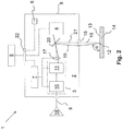
- FIG. 1 shows an adjustment arrangement 1 in a schematic representation, with which a beam position system 3 of a scanner head 2 for laser material processing can be adjusted.
- the alignment arrangement 1 comprises, in addition to the beam position system 3, a beam position sensor 4, a computing unit 5, a memory 6 and / or a control unit 7 FIG. 1 illustrated embodiment, the adjustment assembly 1 is completely integrated in the scanner head 2. You are thus inside a scanner housing 8.
- the position of the laser beam 9 can be influenced.
- the beam position system 3 comprises at least two controllable by the control unit 7 optical elements, which are not shown in detail in the figures. These optical elements are preferably rotatably mounted mirrors, which can be controlled by means of an actuator.
- the beam position system 3 comprises a deflection unit 11.
- the deflection unit 11 is designed such that by means of this a processing location 12 in which the laser beam 9 impinges on a processing surface 13 of a workpiece 14, two-dimensionally, i. in the x and y direction, can be moved on the processing surface 13.
- the deflection unit 11 preferably comprises two mirrors, which are each mounted rotatably only about a single axis of rotation.
- the method of the processing location 12 can be generated on the processing surface 13 in the x-direction over the first mirror and in the y-direction over the second mirror.
- the beam position system 3 comprises a parallel offset unit 10.
- the parallel offset unit 10 of the deflection unit 11 is preferably arranged in front of it.
- an angle of incidence of the laser beam 9 on the processing surface 13 can be adjusted. This is done via a parallel displacement of the laser beam 9 perpendicular to an optical axis 16 of a focusing optical system 15.
- the focusing optical system 15 is accordingly downstream of the beam positioning system 3, in particular of the parallel displacement unit 10, in the propagation direction of the laser beam 9.
- the laser beam 9 can be focused in the processing location 12 on the processing surface 13 of the workpiece 14.
- the parallel offset unit 10 comprises at least two rotatable mirrors.
- an angle of inclination ⁇ of the laser beam 9 can be set. Accordingly, for example by means of a first movable mirror in a xz plane, a first inclination angle and by means of the second movable mirror in a yz plane, a second inclination angle can be adjusted.
- the parallel displacement of the laser beam 9 can also take place via two successive movable, in particular rotatable or tiltable, optical disks.
- the scanner head 2 for laser material processing shown further comprises a focus adjusting unit 17.
- the laser beam 9 can be changed in a z-direction.
- a lens of the focus adjusting unit 17 is axially displaceable in the propagation direction of the laser beam.
- the focus adjusting unit 17 is disposed between the beam placing system 3 and the focusing lens 15 according to the present embodiment.
- the focus setting unit 17 could also be formed by the focusing optics 15.
- the focusing optics 15 would be axially displaceable for changing the focal position of the laser beam 9 in the z direction relative to its optical axis 16.
- the scanner head 2 has a control unit 7.
- the control unit 7 is according to FIG. 1 with the beam position system 3, namely in particular with the Parallelversatztician 10 and the deflector 11 connected.
- the control unit 7 can be used to control the movable optical elements, in particular mirrors, not shown in detail in the figures.
- the parallel offset unit 10 the angle of incidence and by means of the deflection unit 11, the position of the processing location 12 in the xy plane can be adjusted.
- the control unit 7 is electrically connected to the focus setting unit 17, so that by means of this the focus position in the z direction is adjustable.
- a problem with the customer's commissioning of the scanner head 2 is that the laser beam 9 generated by a laser source 18 enters the scanner head 2 in a misaligned manner. This adjustment error thus continues even in the factory properly calibrated beam positioning system 3 in the beam propagation direction over all components of the scanner head 2, ie on the Parallelversatztician 10 and the deflection 11 continues.
- this adjustment error coupled in front of the beam position system 3 comprises the scanner head 2 according to the in FIG. 1 illustrated embodiment, at least parts of the adjustment arrangement 1, wherein the adjustment arrangement according to the first embodiment is fully integrated in the scanner head 2.
- the beam position sensor 4 forms a component of the adjustment arrangement. With the beam position sensor 4, an actual position 19 of the laser beam 9 in the region of the beam path between the beam position system 3 and the focusing optics 15 can be detected.
- the beam position sensor 4 is downstream of the beam position system 3 in the propagation direction of the laser beam 9.
- the beam position sensor 4 of the focusing optical system 15 is arranged upstream in the propagation direction of the laser beam 9. Accordingly, the beam position sensor 4 is integrated in the scanner head 2 in such a way that it can detect the actual position 19 of the laser beam 9 in the region of the beam path between the beam position system 3 and the focusing optical system 15.
- a beam splitter 20 is disposed between the beam position system 3 and the focusing optics 15.
- the beam splitter 20 is formed as a semi-transparent mirror.
- the laser beam 9 can be coupled out of the optical path leading to the focusing optical system 15 without its actual position 19 being changed.
- the decoupled part of the laser beam 9 can now be detected by means of the beam position sensor 4.
- the beam position sensor 4 and the beam splitter 20 are arranged to each other such that the laser light transmitted by the beam splitter is directed to the beam position sensor 4 and the laser light reflected from the beam splitter 20 to the focusing lens 15.
- the actual position 19 of the laser beam 9 is determined according to the invention by at least four independent position parameters of the laser beam 9. By detecting these at least four independent position parameters, the beam position sensor 4 thus indirectly senses the actual position 19 of the laser beam 9 in the region between the beam position system 3 and the focusing optics 15.
- the positional parameters for determining the actual position 19 of the laser beam 9 may be translational and / or rotational position parameters.
- the beam position sensor 4 is connected to the arithmetic unit 5 presently integrated in the scanner head 2.
- the position parameters or the actual position 19 of the laser beam 9 determined by the connection can be transmitted to the arithmetic unit 5 via this connection.
- the adjustment arrangement 1 further comprises the memory 6, in which a desired position 21 of the laser beam 9 is stored.
- the desired position 21 is that position of the laser beam 9, which should have this in the area between the beam position system 3 and the focusing optics 15.
- this target position 21 is now set and / or adjusted.
- the setpoint position 21 of the laser beam 9 or the at least four positional parameters 21 determining the positional parameters were determined at the factory for this purpose prior to delivery of the scanner head 2. In this factory calibration process manufacturing tolerances of the beam position system 3 and / or the focus adjustment unit 17 can thus be considered.
- the factory determined target position 21 of the laser beam 9 is stored in the memory 6.
- the memory 6 may be a separate unit or else integrated in the arithmetic unit 5.
- the arithmetic unit 5 compares the detected by means of the beam position sensor 4 actual position 19 with the factory determined and / or stored in the memory 6 target position 21 of the laser beam 9. If a the beam position system 3 upstream adjustment error is present, the arithmetic unit 5 may be a deviation of the actual Position 19 of the desired target position 21 determine. In this case, the arithmetic unit 5 calculates a correction value. This correction value determines a readjustment of the beam position system 3, in particular the parallel offset unit 10 and / or the deflection unit 11, to be performed. For the calculation of the correction value, the arithmetic unit 5 uses an iterative approximation method and / or a stochastic search method.
- the arithmetic unit 5 is connected to the control unit 7. As a result, the correction value determined by the arithmetic unit 5 can be transmitted to the control unit 7. By means of the correction value, a readjustment of the beam position system 3, in particular of at least one optical element of the parallel offset unit 10 and / or the deflection unit 11, is now carried out via the control unit 7.
- the adjustment method described above may also be designed as a control loop, wherein the actual position 19 of the readjusted by means of the correction value laser beam 9 is detected again sensory by the beam position sensor 4 and the computing unit 5 in the context of another actual / target position adjustment is checked. This process can be carried out until the actual position 19 is within a predetermined tolerance range.
- the above adjustment procedure is not online - i. not during the machining process - but offline according to the invention - i. before the start of the actual machining process. Accordingly, the offline adjustment takes place, for example, when the scanner head is installed by the customer and / or within predetermined time intervals in order to be able to correct temperature-related or wear-related maladjustments.
- FIG. 2 shows the adjustment arrangement 1 according to a second embodiment.
- the same reference numerals used corresponds their design and / or mode of action those of the features already described above.
- FIG. 2 illustrated alignment arrangement 1 includes, as well as the embodiment shown in Figure 1, a beam position sensor 4 for detecting the actual position 19 of the laser beam 9, a computing unit 5 for performing an actual / setpoint adjustment and / or for calculating a correction value, a control unit 7 for readjusting the beam position system 3 taking into account the at least one correction value and the beam position system 3 for influencing the laser beam position.
- the arithmetic unit 5 is designed as an external arithmetic unit.
- the scanner head 2 has an external interface 22. This may be a wired and / or wireless interface.
- the memory 6 with its desired position of the laser beam 9 determining data is preferably, as in FIG. 2 represented integrated in the scanner head 2. In this way, it can be ensured that the setpoint position determined at the factory is assigned individually to the respective scanner head 2 checked at the factory. Alternatively, however, it is also conceivable that the memory 6 is integrated with the stored desired position 21 in the external computer unit 5.
- the beam position sensor 4 is designed such that at least four positional parameters of the laser beam 9 can be detected by means of this according to the invention.
- the beam position sensor 4 can thus also be referred to as a 4D sensor.
- the actual position 19 of the laser beam 9 is determined.
- the beam position sensor 4 thus indirectly detects the actual position via the four position parameters 19 of the laser beam 9.
- the position parameters here can be translational and / or rotational position parameters.
- two translational position parameters are determined by means of a first two-dimensional sensor 23. These may be an x-coordinate and a y-coordinate with respect to a beam position sensor coordinate system.
- the beam position sensor 4 has a second two-dimensional sensor 24. By means of this two rotational position parameters are determined.
- a sensor lens 25 is connected upstream of the second sensor 24 in the propagation direction of the laser beam 9. Through this, a defined deflection of the laser beam, whereby an angle measurement is made possible.
- a sensor beam splitter 26 is disposed in front of it.
- the actual position 19 according to the in FIG. 4 illustrated embodiment by means of two to the sensor beam splitter 26 in mutually different distances 27, 28 arranged sensors 23, 24 are determined.
- a first x-coordinate and first y-coordinate are detected and by means of the second sensor 24 a second x-coordinate and second y-coordinate.
- the x-coordinate, y-coordinate and the angle of incidence of the laser beam relative to this reference plane can thus be calculated with respect to a reference plane.
- the sensors 23, 24 can be, for example, imaging sensors, in particular camera chips.
- position-sensitive multi-surface diodes (quadrant diodes) and / or wavefront sensors are conceivable.
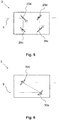
- FIG. 5 shows an embodiment of the beam position system 3 in which the beam position can be adjusted by means of four rotatable single-axis mirrors 29a, 29b, 29c, 29d.
- Each of these single-axis mirrors 29a, 29b, 29c, 29d is rotatable only about a single axis of rotation. Since the axes of rotation are not all parallel to one another and the mirrors are arranged at different locations, the four degrees of freedom of rotation of the axes of rotation provide four degrees of freedom of adjustment for the beam position.
- This embodiment of the beam position system 3 is also an example of a beam position system 3, which is not constructed of two separate subsystems, ie a separate parallel offset unit 10 and a separate deflection unit 11, but the functions of parallel displacement and tilt of the beam in a single system are integrated.
- FIG. 6 shows a second embodiment of the beam position system 3, in which the beam position can be adjusted by means of two tiltable about two axes of rotation biaxial mirrors 30a, 30b. Due to the two times two degrees of freedom of Spiegelverkippung four StellDeutschsgrade for the beam position are provided.
- This embodiment of the beam position system 3 is another example of a beam position system that is not constructed of two subsystems, but provides the functions of parallel displacement and tilt of the beam integrated into a single mirror unit.
- a drive of the mirror via galvanometer drives is particularly advantageous to allow a very dynamic and at the same time very accurate adjustment of the beam position.
- the galvanometer drives in the beam position system 3 are preferably operated in online operation in a closed loop position control, which is designed independently of the beam position sensor 4. It is therefore based on an independent of the beam position sensor 4 position measurement in the galvanometer drives.
Landscapes
- Physics & Mathematics (AREA)
- Optics & Photonics (AREA)
- Engineering & Computer Science (AREA)
- Plasma & Fusion (AREA)
- Mechanical Engineering (AREA)
- Laser Beam Processing (AREA)
- Mechanical Optical Scanning Systems (AREA)
- Length Measuring Devices By Optical Means (AREA)
Applications Claiming Priority (2)
| Application Number | Priority Date | Filing Date | Title |
|---|---|---|---|
| DE102015109984.5A DE102015109984A1 (de) | 2015-06-22 | 2015-06-22 | Scannerkopf mit integriertem Strahllagesensor sowie Justageanordnung zur Offline-Justage |
| PCT/EP2016/062577 WO2016206943A1 (de) | 2015-06-22 | 2016-06-03 | Scannerkopf mit integriertem strahllagesensor sowie justageanordnung zur offline-justage |
Publications (2)
| Publication Number | Publication Date |
|---|---|
| EP3310519A1 EP3310519A1 (de) | 2018-04-25 |
| EP3310519B1 true EP3310519B1 (de) | 2019-11-13 |
Family
ID=56097133
Family Applications (1)
| Application Number | Title | Priority Date | Filing Date |
|---|---|---|---|
| EP16726594.1A Active EP3310519B1 (de) | 2015-06-22 | 2016-06-03 | Justageanordnung zur offline-justage mit einem scannerkopf mit integriertem strahllagesensor sowie entsprechendes justageverfahren unterverwendung einer solchen justageanordnung |
Country Status (7)
| Country | Link |
|---|---|
| US (1) | US10773339B2 (enExample) |
| EP (1) | EP3310519B1 (enExample) |
| JP (1) | JP6821606B2 (enExample) |
| KR (1) | KR20180020207A (enExample) |
| CN (1) | CN107771112B (enExample) |
| DE (1) | DE102015109984A1 (enExample) |
| WO (1) | WO2016206943A1 (enExample) |
Cited By (2)
| Publication number | Priority date | Publication date | Assignee | Title |
|---|---|---|---|---|
| WO2022043016A1 (de) * | 2020-08-26 | 2022-03-03 | Jenoptik Optical Systems Gmbh | Verfahren und steuergerät zur kalibrierung einer laser-scanner-vorrichtung zur materialbearbeitung |
| DE102021130944A1 (de) | 2021-11-25 | 2023-05-25 | Jenoptik Optical Systems Gmbh | Vorrichtung und Verfahren zum Bestimmen eines Strahlverlaufs eines Strahls und Laseranlage |
Families Citing this family (24)
| Publication number | Priority date | Publication date | Assignee | Title |
|---|---|---|---|---|
| JP6487413B2 (ja) * | 2016-12-22 | 2019-03-20 | ファナック株式会社 | レーザ加工用ヘッドおよびそれを備えたレーザ加工システム |
| DE102017125120A1 (de) * | 2017-10-26 | 2019-05-02 | Scanlab Gmbh | Steuerungsverfahren zur Bewegungsführung eines Laserstrahls mit Interpolation der Fokuslage und/oder Strahlrichtung |
| US10705327B2 (en) | 2018-01-02 | 2020-07-07 | Industrial Technology Research Institute | Light emitting method and light emitting device |
| DE102018105877B3 (de) * | 2018-03-14 | 2019-02-28 | Precitec Gmbh & Co. Kg | Vorrichtung für die Bestimmung einer Ausrichtung einer optischen Vorrichtung eines Kohärenztomographen, Kohärenztomograph und Laserbearbeitungssystem |
| KR102106068B1 (ko) * | 2018-05-09 | 2020-05-04 | (주)엔피에스 | 레이저 장치 |
| BE1026484B1 (fr) | 2018-07-24 | 2020-02-25 | Laser Eng Applications | Méthode et dispositif optique pour fournir deux faisceaux laser décalés |
| DE112019004004T5 (de) * | 2018-08-09 | 2021-05-20 | Corning Incorporated | Systeme, verfahren und geräte zum maschinengebundenen profilieren eines laserstrahls |
| DE102018219129B3 (de) * | 2018-11-09 | 2019-11-07 | Trumpf Laser Gmbh | Verfahren und Computerprogrammprodukt zur OCT-Messstrahljustierung |
| CN109483047B (zh) * | 2018-11-15 | 2019-12-31 | 中国科学院西安光学精密机械研究所 | 一种激光光束终端指向检测与校正方法及激光加工装置 |
| US11273520B2 (en) * | 2019-01-31 | 2022-03-15 | General Electric Company | System and method for automated laser ablation |
| DE102019115554A1 (de) * | 2019-06-07 | 2020-12-10 | Bystronic Laser Ag | Bearbeitungsvorrichtung zur Laserbearbeitung eines Werkstücks und Verfahren zur Laserbearbeitung eines Werkstücks |
| US11305377B2 (en) * | 2019-12-23 | 2022-04-19 | Precitec Gmbh & Co. Kg | Add-on module for interposing between a control device and a laser machining head of a laser machining system |
| US20230166359A1 (en) | 2020-04-30 | 2023-06-01 | Nikon Corporation | Processing system |
| PT3907317T (pt) * | 2020-05-08 | 2022-05-06 | Jeanologia Sl | Dispositivo e processo para o tratamento a laser de calças que compreende dois manequins |
| US20230341679A1 (en) | 2020-08-18 | 2023-10-26 | Nikon Corporation | Optical apparatus and processing apparatus |
| JP7240774B2 (ja) * | 2020-10-16 | 2023-03-16 | 国立大学法人信州大学 | 光学ユニット及びレーザー加工装置 |
| JP2022065693A (ja) * | 2020-10-16 | 2022-04-28 | 国立大学法人信州大学 | 光学ユニット、並びにレーザー加工装置、レーザー加工方法、及び三次元加工装置 |
| DE102020214566B4 (de) | 2020-11-19 | 2023-08-03 | Robert Bosch Gesellschaft mit beschränkter Haftung | Bestimmungsvorrichtung zur Bestimmung der Lage und Richtung eines Laserstrahls und System und Verfahren zum Einstellen der Lage und Richtung eines Laserstrahls |
| CN112846485B (zh) * | 2020-12-31 | 2022-11-04 | 武汉华工激光工程有限责任公司 | 激光加工的监测方法、装置及激光加工设备 |
| IL312370A (en) | 2021-10-25 | 2025-01-01 | Trumpf Lasersystems Semiconductor Mfg Gmbh | Deep ultraviolet light source if beam positioning device |
| JP2023067484A (ja) * | 2021-11-01 | 2023-05-16 | キヤノン株式会社 | 光軸検出装置、光軸補正装置、加工装置、および、物品の製造方法 |
| KR102728044B1 (ko) * | 2022-07-18 | 2024-11-08 | (주)알엔알랩 | 기판 처리 장치 및 방법 |
| CN119115265B (zh) * | 2024-11-14 | 2025-01-24 | 西南交通大学 | 一种激光切割材料板的方法 |
| CN119566543A (zh) * | 2024-12-20 | 2025-03-07 | 中国科学院西安光学精密机械研究所 | 一种用于复杂结构的激光三维体制造装置及方法 |
Citations (2)
| Publication number | Priority date | Publication date | Assignee | Title |
|---|---|---|---|---|
| DE102012111090A1 (de) * | 2012-11-19 | 2014-03-20 | Scanlab Ag | Vorrichtung zur Änderung der Länge eines Strahlenganges |
| DE102013222834A1 (de) * | 2013-11-11 | 2015-05-13 | Robert Bosch Gmbh | Vorrichtung und Verfahren zur Führung eines Laserstrahls |
Family Cites Families (12)
| Publication number | Priority date | Publication date | Assignee | Title |
|---|---|---|---|---|
| DE29612073U1 (de) * | 1996-07-11 | 1997-11-06 | Sator, Alexander Paul, 20249 Hamburg | Vorrichtung zur Überprüfung von Werkstückflächen, die mit Hilfe eines Laserstrahls markiert und/oder bearbeitet werden |
| JPH10137962A (ja) | 1996-11-07 | 1998-05-26 | Matsushita Electric Ind Co Ltd | レーザ光学系 |
| US6548796B1 (en) * | 1999-06-23 | 2003-04-15 | Regents Of The University Of Minnesota | Confocal macroscope |
| US7358157B2 (en) * | 2002-03-27 | 2008-04-15 | Gsi Group Corporation | Method and system for high-speed precise laser trimming, scan lens system for use therein and electrical device produced thereby |
| US20030222143A1 (en) * | 2002-06-04 | 2003-12-04 | Mitchell Phillip V. | Precision laser scan head |
| DE10335501B4 (de) | 2002-07-31 | 2005-01-27 | Kuka Schweissanlagen Gmbh | Verfahren und Vorrichtung zum Schweißen oder Schneiden mit Laserstrahl |
| JP2005118815A (ja) | 2003-10-16 | 2005-05-12 | Hitachi Via Mechanics Ltd | レーザ加工方法およびレーザ加工装置 |
| DE102004053298B4 (de) | 2004-08-26 | 2008-10-09 | ARGES Gesellschaft für Industrieplanung und Lasertechnik m.b.H. | Scankopf als Teil einer Laser Bohr- und Schneideinrichtung |
| DE102006047277A1 (de) * | 2006-10-04 | 2008-04-10 | Lt Ultra-Precision-Technology Gmbh | Verfahren und Vorrichtung zum Laserstrahlbearbeiten |
| WO2008118365A1 (en) * | 2007-03-22 | 2008-10-02 | General Lasertronics Corporation | Methods for stripping and modifying surfaces with laser-induced ablation |
| US9511448B2 (en) * | 2009-12-30 | 2016-12-06 | Resonetics, LLC | Laser machining system and method for machining three-dimensional objects from a plurality of directions |
| DE102010005896A1 (de) * | 2010-01-27 | 2010-10-14 | Daimler Ag | Laserschweißroboter und -verfahren sowie damit hergestelltes Bauteil |
-
2015
- 2015-06-22 DE DE102015109984.5A patent/DE102015109984A1/de not_active Ceased
-
2016
- 2016-06-03 WO PCT/EP2016/062577 patent/WO2016206943A1/de not_active Ceased
- 2016-06-03 EP EP16726594.1A patent/EP3310519B1/de active Active
- 2016-06-03 JP JP2017566141A patent/JP6821606B2/ja active Active
- 2016-06-03 US US15/736,905 patent/US10773339B2/en active Active
- 2016-06-03 CN CN201680036408.1A patent/CN107771112B/zh active Active
- 2016-06-03 KR KR1020187000548A patent/KR20180020207A/ko not_active Withdrawn
Patent Citations (2)
| Publication number | Priority date | Publication date | Assignee | Title |
|---|---|---|---|---|
| DE102012111090A1 (de) * | 2012-11-19 | 2014-03-20 | Scanlab Ag | Vorrichtung zur Änderung der Länge eines Strahlenganges |
| DE102013222834A1 (de) * | 2013-11-11 | 2015-05-13 | Robert Bosch Gmbh | Vorrichtung und Verfahren zur Führung eines Laserstrahls |
Cited By (2)
| Publication number | Priority date | Publication date | Assignee | Title |
|---|---|---|---|---|
| WO2022043016A1 (de) * | 2020-08-26 | 2022-03-03 | Jenoptik Optical Systems Gmbh | Verfahren und steuergerät zur kalibrierung einer laser-scanner-vorrichtung zur materialbearbeitung |
| DE102021130944A1 (de) | 2021-11-25 | 2023-05-25 | Jenoptik Optical Systems Gmbh | Vorrichtung und Verfahren zum Bestimmen eines Strahlverlaufs eines Strahls und Laseranlage |
Also Published As
| Publication number | Publication date |
|---|---|
| JP2018525227A (ja) | 2018-09-06 |
| US20180169788A1 (en) | 2018-06-21 |
| CN107771112A (zh) | 2018-03-06 |
| JP6821606B2 (ja) | 2021-01-27 |
| KR20180020207A (ko) | 2018-02-27 |
| DE102015109984A1 (de) | 2016-12-22 |
| CN107771112B (zh) | 2020-06-05 |
| WO2016206943A1 (de) | 2016-12-29 |
| US10773339B2 (en) | 2020-09-15 |
| EP3310519A1 (de) | 2018-04-25 |
Similar Documents
| Publication | Publication Date | Title |
|---|---|---|
| EP3310519B1 (de) | Justageanordnung zur offline-justage mit einem scannerkopf mit integriertem strahllagesensor sowie entsprechendes justageverfahren unterverwendung einer solchen justageanordnung | |
| DE102018105877B3 (de) | Vorrichtung für die Bestimmung einer Ausrichtung einer optischen Vorrichtung eines Kohärenztomographen, Kohärenztomograph und Laserbearbeitungssystem | |
| DE102014113283B4 (de) | Vorrichtung zur Remote-Laserbearbeitung mit Sensor-Scannereinrichtung | |
| EP3049755B1 (de) | Verfahren zum messen der eindringtiefe eines laserstrahls in ein werkstück sowie laserbearbeitungsvorrichtung | |
| DE102015012565B3 (de) | Vorrichtung und Verfahren zur Erhöhung der Genauigkeit eines OCT-Messsystems für die Lasermaterialbearbeitung | |
| DE102013008269B4 (de) | Bearbeitungskopf für eine Laserbearbeitungsvorrichtung und Verfahren zur Laserbearbeitung eines Werkstücks | |
| DE102016106648B4 (de) | Kalibrierverfahren für ein Sensor-Ablenksystem einer Laserbearbeitungsvorrichtung sowie Kalibriersystem zur Durchführung eines derartigen Kalibrierverfahrens | |
| DE102017115922C5 (de) | Verfahren und Vorrichtung zur Messung und Einstellung eines Abstands zwischen einem Bearbeitungskopf und einem Werkstück sowie dazugehöriges Verfahren zur Regelung | |
| DE102018129407B4 (de) | Verfahren zum Schneiden eines Werkstücks mittels eines Laserstrahls und Laserbearbeitungssystem zum Durchführen des Verfahrens | |
| DE19963010B4 (de) | Verfahren und Vorrichtung zur Laserbearbeitung von Werkstücken | |
| WO2017153408A1 (de) | Achsenkalibrieren einer strahlbearbeitungsmaschine | |
| EP3313607B1 (de) | Laserbearbeitungskopf und laserbearbeitungsmaschine damit | |
| EP2621662B1 (de) | Vorrichtung und verfahren für die bearbeitung von material mit fokussierter elektromagnetischer strahlung | |
| DE102019120398B3 (de) | Laserbearbeitungssystem und Verfahren für eine zentrische Ausrichtung eines Laserstrahls in einem Bearbeitungskopf eines Laserbearbeitungssystems | |
| WO2016128287A1 (de) | Mehrkopf-laseranlage mit sensoreinheit in kombination mit einem beweglichen optischen führungselement | |
| DE102017215973A1 (de) | Vorrichtung und Verfahren zur Bestimmung der Strahllage eines Laserstrahls | |
| WO2006119734A1 (de) | Verfahren und vorrichtung zur bestimmung einer lateralen relativbewegung zwischen einem bearbeitungskopf und einem werkstück | |
| EP3146293B1 (de) | Vorrichtung und verfahren zur geometrischen vermessung eines objekts | |
| WO2019149872A1 (de) | Vorrichtung zur lasermaterialbearbeitung mit einer eine relayoptik aufweisenden sensoreinheit | |
| WO2024037828A1 (de) | Verfahren zur kalibrierung eines mess-scanners an einer laserbearbeitungsoptik | |
| DE102021127917A1 (de) | Verfahren und System zum Einstellen einer Referenzstrecke eines OCT-Systems | |
| DE102017201794B4 (de) | Prüfvorrichtung als Bestandteil eines Reflektometers zur Bestimmung einer Strahllage eines Lichtstrahls | |
| DE102017210098B4 (de) | Scanvorrichtung mit einer Scankopfvorrichtung zum Reflektieren oder Transmittieren von Strahlen für einen Scanner sowie Verfahren zum Reflektieren oder Transmittieren von Strahlen für einen Scanner | |
| EP3833930B1 (de) | Vorrichtung und verfahren zur geometrischen vermessung eines objekts | |
| EP4488615A1 (de) | Optische kohärenztomografie-vorrichtung für ein laserbearbeitungssystem sowie laserbearbeitungssystem mit derselben |
Legal Events
| Date | Code | Title | Description |
|---|---|---|---|
| STAA | Information on the status of an ep patent application or granted ep patent |
Free format text: STATUS: THE INTERNATIONAL PUBLICATION HAS BEEN MADE |
|
| PUAI | Public reference made under article 153(3) epc to a published international application that has entered the european phase |
Free format text: ORIGINAL CODE: 0009012 |
|
| STAA | Information on the status of an ep patent application or granted ep patent |
Free format text: STATUS: REQUEST FOR EXAMINATION WAS MADE |
|
| 17P | Request for examination filed |
Effective date: 20180122 |
|
| AK | Designated contracting states |
Kind code of ref document: A1 Designated state(s): AL AT BE BG CH CY CZ DE DK EE ES FI FR GB GR HR HU IE IS IT LI LT LU LV MC MK MT NL NO PL PT RO RS SE SI SK SM TR |
|
| AX | Request for extension of the european patent |
Extension state: BA ME |
|
| RIN1 | Information on inventor provided before grant (corrected) |
Inventor name: SONNER, CHRISTIAN Inventor name: RABE, MATTHIAS |
|
| STAA | Information on the status of an ep patent application or granted ep patent |
Free format text: STATUS: EXAMINATION IS IN PROGRESS |
|
| 17Q | First examination report despatched |
Effective date: 20180823 |
|
| DAV | Request for validation of the european patent (deleted) | ||
| DAX | Request for extension of the european patent (deleted) | ||
| GRAP | Despatch of communication of intention to grant a patent |
Free format text: ORIGINAL CODE: EPIDOSNIGR1 |
|
| STAA | Information on the status of an ep patent application or granted ep patent |
Free format text: STATUS: GRANT OF PATENT IS INTENDED |
|
| INTG | Intention to grant announced |
Effective date: 20190528 |
|
| GRAS | Grant fee paid |
Free format text: ORIGINAL CODE: EPIDOSNIGR3 |
|
| GRAA | (expected) grant |
Free format text: ORIGINAL CODE: 0009210 |
|
| STAA | Information on the status of an ep patent application or granted ep patent |
Free format text: STATUS: THE PATENT HAS BEEN GRANTED |
|
| AK | Designated contracting states |
Kind code of ref document: B1 Designated state(s): AL AT BE BG CH CY CZ DE DK EE ES FI FR GB GR HR HU IE IS IT LI LT LU LV MC MK MT NL NO PL PT RO RS SE SI SK SM TR |
|
| REG | Reference to a national code |
Ref country code: CH Ref legal event code: EP Ref country code: AT Ref legal event code: REF Ref document number: 1201157 Country of ref document: AT Kind code of ref document: T Effective date: 20191115 |
|
| REG | Reference to a national code |
Ref country code: DE Ref legal event code: R096 Ref document number: 502016007573 Country of ref document: DE |
|
| REG | Reference to a national code |
Ref country code: IE Ref legal event code: FG4D Free format text: LANGUAGE OF EP DOCUMENT: GERMAN |
|
| REG | Reference to a national code |
Ref country code: NL Ref legal event code: FP |
|
| REG | Reference to a national code |
Ref country code: LT Ref legal event code: MG4D |
|
| PG25 | Lapsed in a contracting state [announced via postgrant information from national office to epo] |
Ref country code: PT Free format text: LAPSE BECAUSE OF FAILURE TO SUBMIT A TRANSLATION OF THE DESCRIPTION OR TO PAY THE FEE WITHIN THE PRESCRIBED TIME-LIMIT Effective date: 20200313 Ref country code: PL Free format text: LAPSE BECAUSE OF FAILURE TO SUBMIT A TRANSLATION OF THE DESCRIPTION OR TO PAY THE FEE WITHIN THE PRESCRIBED TIME-LIMIT Effective date: 20191113 Ref country code: LT Free format text: LAPSE BECAUSE OF FAILURE TO SUBMIT A TRANSLATION OF THE DESCRIPTION OR TO PAY THE FEE WITHIN THE PRESCRIBED TIME-LIMIT Effective date: 20191113 Ref country code: GR Free format text: LAPSE BECAUSE OF FAILURE TO SUBMIT A TRANSLATION OF THE DESCRIPTION OR TO PAY THE FEE WITHIN THE PRESCRIBED TIME-LIMIT Effective date: 20200214 Ref country code: NO Free format text: LAPSE BECAUSE OF FAILURE TO SUBMIT A TRANSLATION OF THE DESCRIPTION OR TO PAY THE FEE WITHIN THE PRESCRIBED TIME-LIMIT Effective date: 20200213 Ref country code: LV Free format text: LAPSE BECAUSE OF FAILURE TO SUBMIT A TRANSLATION OF THE DESCRIPTION OR TO PAY THE FEE WITHIN THE PRESCRIBED TIME-LIMIT Effective date: 20191113 Ref country code: SE Free format text: LAPSE BECAUSE OF FAILURE TO SUBMIT A TRANSLATION OF THE DESCRIPTION OR TO PAY THE FEE WITHIN THE PRESCRIBED TIME-LIMIT Effective date: 20191113 Ref country code: BG Free format text: LAPSE BECAUSE OF FAILURE TO SUBMIT A TRANSLATION OF THE DESCRIPTION OR TO PAY THE FEE WITHIN THE PRESCRIBED TIME-LIMIT Effective date: 20200213 Ref country code: FI Free format text: LAPSE BECAUSE OF FAILURE TO SUBMIT A TRANSLATION OF THE DESCRIPTION OR TO PAY THE FEE WITHIN THE PRESCRIBED TIME-LIMIT Effective date: 20191113 |
|
| PG25 | Lapsed in a contracting state [announced via postgrant information from national office to epo] |
Ref country code: RS Free format text: LAPSE BECAUSE OF FAILURE TO SUBMIT A TRANSLATION OF THE DESCRIPTION OR TO PAY THE FEE WITHIN THE PRESCRIBED TIME-LIMIT Effective date: 20191113 Ref country code: HR Free format text: LAPSE BECAUSE OF FAILURE TO SUBMIT A TRANSLATION OF THE DESCRIPTION OR TO PAY THE FEE WITHIN THE PRESCRIBED TIME-LIMIT Effective date: 20191113 Ref country code: IS Free format text: LAPSE BECAUSE OF FAILURE TO SUBMIT A TRANSLATION OF THE DESCRIPTION OR TO PAY THE FEE WITHIN THE PRESCRIBED TIME-LIMIT Effective date: 20200313 |
|
| PG25 | Lapsed in a contracting state [announced via postgrant information from national office to epo] |
Ref country code: AL Free format text: LAPSE BECAUSE OF FAILURE TO SUBMIT A TRANSLATION OF THE DESCRIPTION OR TO PAY THE FEE WITHIN THE PRESCRIBED TIME-LIMIT Effective date: 20191113 |
|
| PG25 | Lapsed in a contracting state [announced via postgrant information from national office to epo] |
Ref country code: EE Free format text: LAPSE BECAUSE OF FAILURE TO SUBMIT A TRANSLATION OF THE DESCRIPTION OR TO PAY THE FEE WITHIN THE PRESCRIBED TIME-LIMIT Effective date: 20191113 Ref country code: DK Free format text: LAPSE BECAUSE OF FAILURE TO SUBMIT A TRANSLATION OF THE DESCRIPTION OR TO PAY THE FEE WITHIN THE PRESCRIBED TIME-LIMIT Effective date: 20191113 Ref country code: ES Free format text: LAPSE BECAUSE OF FAILURE TO SUBMIT A TRANSLATION OF THE DESCRIPTION OR TO PAY THE FEE WITHIN THE PRESCRIBED TIME-LIMIT Effective date: 20191113 Ref country code: RO Free format text: LAPSE BECAUSE OF FAILURE TO SUBMIT A TRANSLATION OF THE DESCRIPTION OR TO PAY THE FEE WITHIN THE PRESCRIBED TIME-LIMIT Effective date: 20191113 Ref country code: CZ Free format text: LAPSE BECAUSE OF FAILURE TO SUBMIT A TRANSLATION OF THE DESCRIPTION OR TO PAY THE FEE WITHIN THE PRESCRIBED TIME-LIMIT Effective date: 20191113 |
|
| REG | Reference to a national code |
Ref country code: DE Ref legal event code: R097 Ref document number: 502016007573 Country of ref document: DE |
|
| PG25 | Lapsed in a contracting state [announced via postgrant information from national office to epo] |
Ref country code: SM Free format text: LAPSE BECAUSE OF FAILURE TO SUBMIT A TRANSLATION OF THE DESCRIPTION OR TO PAY THE FEE WITHIN THE PRESCRIBED TIME-LIMIT Effective date: 20191113 Ref country code: SK Free format text: LAPSE BECAUSE OF FAILURE TO SUBMIT A TRANSLATION OF THE DESCRIPTION OR TO PAY THE FEE WITHIN THE PRESCRIBED TIME-LIMIT Effective date: 20191113 |
|
| PLBE | No opposition filed within time limit |
Free format text: ORIGINAL CODE: 0009261 |
|
| STAA | Information on the status of an ep patent application or granted ep patent |
Free format text: STATUS: NO OPPOSITION FILED WITHIN TIME LIMIT |
|
| 26N | No opposition filed |
Effective date: 20200814 |
|
| PG25 | Lapsed in a contracting state [announced via postgrant information from national office to epo] |
Ref country code: SI Free format text: LAPSE BECAUSE OF FAILURE TO SUBMIT A TRANSLATION OF THE DESCRIPTION OR TO PAY THE FEE WITHIN THE PRESCRIBED TIME-LIMIT Effective date: 20191113 |
|
| PG25 | Lapsed in a contracting state [announced via postgrant information from national office to epo] |
Ref country code: MC Free format text: LAPSE BECAUSE OF FAILURE TO SUBMIT A TRANSLATION OF THE DESCRIPTION OR TO PAY THE FEE WITHIN THE PRESCRIBED TIME-LIMIT Effective date: 20191113 |
|
| PG25 | Lapsed in a contracting state [announced via postgrant information from national office to epo] |
Ref country code: LU Free format text: LAPSE BECAUSE OF NON-PAYMENT OF DUE FEES Effective date: 20200603 |
|
| PG25 | Lapsed in a contracting state [announced via postgrant information from national office to epo] |
Ref country code: IE Free format text: LAPSE BECAUSE OF NON-PAYMENT OF DUE FEES Effective date: 20200603 |
|
| PG25 | Lapsed in a contracting state [announced via postgrant information from national office to epo] |
Ref country code: TR Free format text: LAPSE BECAUSE OF FAILURE TO SUBMIT A TRANSLATION OF THE DESCRIPTION OR TO PAY THE FEE WITHIN THE PRESCRIBED TIME-LIMIT Effective date: 20191113 Ref country code: MT Free format text: LAPSE BECAUSE OF FAILURE TO SUBMIT A TRANSLATION OF THE DESCRIPTION OR TO PAY THE FEE WITHIN THE PRESCRIBED TIME-LIMIT Effective date: 20191113 Ref country code: CY Free format text: LAPSE BECAUSE OF FAILURE TO SUBMIT A TRANSLATION OF THE DESCRIPTION OR TO PAY THE FEE WITHIN THE PRESCRIBED TIME-LIMIT Effective date: 20191113 |
|
| PG25 | Lapsed in a contracting state [announced via postgrant information from national office to epo] |
Ref country code: MK Free format text: LAPSE BECAUSE OF FAILURE TO SUBMIT A TRANSLATION OF THE DESCRIPTION OR TO PAY THE FEE WITHIN THE PRESCRIBED TIME-LIMIT Effective date: 20191113 |
|
| REG | Reference to a national code |
Ref country code: AT Ref legal event code: MM01 Ref document number: 1201157 Country of ref document: AT Kind code of ref document: T Effective date: 20210603 |
|
| PG25 | Lapsed in a contracting state [announced via postgrant information from national office to epo] |
Ref country code: AT Free format text: LAPSE BECAUSE OF NON-PAYMENT OF DUE FEES Effective date: 20210603 |
|
| PGFP | Annual fee paid to national office [announced via postgrant information from national office to epo] |
Ref country code: NL Payment date: 20230623 Year of fee payment: 8 |
|
| PGFP | Annual fee paid to national office [announced via postgrant information from national office to epo] |
Ref country code: BE Payment date: 20230630 Year of fee payment: 8 |
|
| PGFP | Annual fee paid to national office [announced via postgrant information from national office to epo] |
Ref country code: GB Payment date: 20230622 Year of fee payment: 8 |
|
| REG | Reference to a national code |
Ref country code: NL Ref legal event code: MM Effective date: 20240701 |
|
| GBPC | Gb: european patent ceased through non-payment of renewal fee |
Effective date: 20240603 |
|
| PG25 | Lapsed in a contracting state [announced via postgrant information from national office to epo] |
Ref country code: NL Free format text: LAPSE BECAUSE OF NON-PAYMENT OF DUE FEES Effective date: 20240701 |
|
| PG25 | Lapsed in a contracting state [announced via postgrant information from national office to epo] |
Ref country code: NL Free format text: LAPSE BECAUSE OF NON-PAYMENT OF DUE FEES Effective date: 20240701 |
|
| PG25 | Lapsed in a contracting state [announced via postgrant information from national office to epo] |
Ref country code: BE Free format text: LAPSE BECAUSE OF NON-PAYMENT OF DUE FEES Effective date: 20240630 |
|
| PG25 | Lapsed in a contracting state [announced via postgrant information from national office to epo] |
Ref country code: GB Free format text: LAPSE BECAUSE OF NON-PAYMENT OF DUE FEES Effective date: 20240603 |
|
| REG | Reference to a national code |
Ref country code: BE Ref legal event code: MM Effective date: 20240630 |
|
| PGFP | Annual fee paid to national office [announced via postgrant information from national office to epo] |
Ref country code: DE Payment date: 20250630 Year of fee payment: 10 |
|
| PGFP | Annual fee paid to national office [announced via postgrant information from national office to epo] |
Ref country code: FR Payment date: 20250617 Year of fee payment: 10 |
|
| PGFP | Annual fee paid to national office [announced via postgrant information from national office to epo] |
Ref country code: IT Payment date: 20250627 Year of fee payment: 10 |
|
| PGFP | Annual fee paid to national office [announced via postgrant information from national office to epo] |
Ref country code: CH Payment date: 20250701 Year of fee payment: 10 |