EP3310285B1 - Outil à haute fréquence pour résectoscope médical - Google Patents
Outil à haute fréquence pour résectoscope médical Download PDFInfo
- Publication number
- EP3310285B1 EP3310285B1 EP16787453.6A EP16787453A EP3310285B1 EP 3310285 B1 EP3310285 B1 EP 3310285B1 EP 16787453 A EP16787453 A EP 16787453A EP 3310285 B1 EP3310285 B1 EP 3310285B1
- Authority
- EP
- European Patent Office
- Prior art keywords
- electrode
- carrier
- electrode carrier
- tool
- radiofrequency
- Prior art date
- Legal status (The legal status is an assumption and is not a legal conclusion. Google has not performed a legal analysis and makes no representation as to the accuracy of the status listed.)
- Active
Links
Images
Classifications
-
- A—HUMAN NECESSITIES
- A61—MEDICAL OR VETERINARY SCIENCE; HYGIENE
- A61B—DIAGNOSIS; SURGERY; IDENTIFICATION
- A61B18/00—Surgical instruments, devices or methods for transferring non-mechanical forms of energy to or from the body
- A61B18/04—Surgical instruments, devices or methods for transferring non-mechanical forms of energy to or from the body by heating
- A61B18/12—Surgical instruments, devices or methods for transferring non-mechanical forms of energy to or from the body by heating by passing a current through the tissue to be heated, e.g. high-frequency current
- A61B18/14—Probes or electrodes therefor
- A61B18/149—Probes or electrodes therefor bow shaped or with rotatable body at cantilever end, e.g. for resectoscopes, or coagulating rollers
-
- A—HUMAN NECESSITIES
- A61—MEDICAL OR VETERINARY SCIENCE; HYGIENE
- A61B—DIAGNOSIS; SURGERY; IDENTIFICATION
- A61B18/00—Surgical instruments, devices or methods for transferring non-mechanical forms of energy to or from the body
- A61B2018/00053—Mechanical features of the instrument of device
- A61B2018/00059—Material properties
- A61B2018/00071—Electrical conductivity
- A61B2018/00083—Electrical conductivity low, i.e. electrically insulating
-
- A—HUMAN NECESSITIES
- A61—MEDICAL OR VETERINARY SCIENCE; HYGIENE
- A61B—DIAGNOSIS; SURGERY; IDENTIFICATION
- A61B18/00—Surgical instruments, devices or methods for transferring non-mechanical forms of energy to or from the body
- A61B2018/00315—Surgical instruments, devices or methods for transferring non-mechanical forms of energy to or from the body for treatment of particular body parts
- A61B2018/00547—Prostate
-
- A—HUMAN NECESSITIES
- A61—MEDICAL OR VETERINARY SCIENCE; HYGIENE
- A61B—DIAGNOSIS; SURGERY; IDENTIFICATION
- A61B18/00—Surgical instruments, devices or methods for transferring non-mechanical forms of energy to or from the body
- A61B2018/00571—Surgical instruments, devices or methods for transferring non-mechanical forms of energy to or from the body for achieving a particular surgical effect
- A61B2018/00601—Cutting
-
- A—HUMAN NECESSITIES
- A61—MEDICAL OR VETERINARY SCIENCE; HYGIENE
- A61B—DIAGNOSIS; SURGERY; IDENTIFICATION
- A61B18/00—Surgical instruments, devices or methods for transferring non-mechanical forms of energy to or from the body
- A61B18/04—Surgical instruments, devices or methods for transferring non-mechanical forms of energy to or from the body by heating
- A61B18/12—Surgical instruments, devices or methods for transferring non-mechanical forms of energy to or from the body by heating by passing a current through the tissue to be heated, e.g. high-frequency current
- A61B18/14—Probes or electrodes therefor
- A61B2018/1405—Electrodes having a specific shape
- A61B2018/1407—Loop
- A61B2018/141—Snare
-
- A—HUMAN NECESSITIES
- A61—MEDICAL OR VETERINARY SCIENCE; HYGIENE
- A61B—DIAGNOSIS; SURGERY; IDENTIFICATION
- A61B18/00—Surgical instruments, devices or methods for transferring non-mechanical forms of energy to or from the body
- A61B18/04—Surgical instruments, devices or methods for transferring non-mechanical forms of energy to or from the body by heating
- A61B18/12—Surgical instruments, devices or methods for transferring non-mechanical forms of energy to or from the body by heating by passing a current through the tissue to be heated, e.g. high-frequency current
- A61B18/14—Probes or electrodes therefor
- A61B2018/1405—Electrodes having a specific shape
- A61B2018/144—Wire
Definitions
- the invention relates to a high-frequency tool for medical resectoscopes for manipulating body tissue according to claim 1.
- High-frequency tools are used in medicine to manipulate body tissue, such as removing it. Typical applications include urology, for example, in prostate resection.
- the high-frequency tool may be an RF cutting electrode connected to a high-frequency generator, which can be turned on and off by a surgeon using a switch.
- a cutting loop attached to the HF cutting electrode cuts through the body tissue to be removed very easily and with almost no resistance.
- an electrode carrier of the resectoscope with the high-frequency tool or cutting electrode is moved back and forth axially relative to the resectoscope.
- the forces acting on the tool or cutting loop are essentially parallel to the axial direction of the resectoscope.
- the two ends of the cutting loop are connected to the HF generator, for example, via lead wires.
- the lead wires are first routed through a two-ended forked tube, which can then converge as a single tube to form the loop carrier or electrode carrier.
- This electrode carrier extends toward the proximal end of the resectoscope, in particular toward a Slide of the resectoscope, where the lead wires can be connected to the generator in a known manner. Examples are described in the prior art in US 5 919 189 A , US 2014/088592 A1 , US 6 033 400 A and DE 10 2005 042312 A1 revealed.
- the lead wire(s) are covered with an insulator, such as insulating tubing or plastic tubing.
- an insulator such as insulating tubing or plastic tubing.
- the insulated sections of the cutting electrode, or the ends of the cutting loop, are each first passed through a ceramic tube before being inserted into the electrode carrier.
- These ceramic tubes are inserted into or onto a receptacle at the ends of the electrode carrier.
- the ceramic tubes primarily serve to stabilize the temperature generated at the electrode by the HF generator. Furthermore, the ceramic tubes mechanically stabilize the electrode.
- an electrode or cutting electrode proves to be disadvantageous, particularly for treatment procedures such as enucleation, as the forces acting during enucleation are significantly greater than those acting during tissue resection.
- the electrode is subjected not only to forces in the axial direction of the resectoscope, but also transversely to it. These transverse forces in particular can cause the ceramic tubes to break.
- a short circuit can also occur within the electrode or electrode carrier between the electrode, the lead wires, and the electrode carrier.
- the use of the cutting electrode described above is limited to applications in which only forces in the axial direction of the resectoscope occur and no additional or only minor transverse forces.
- the problem is solved in the state of the art by providing a bracket to stabilize the cutting loop, which absorbs the mechanical forces.
- the disadvantage is that the additional bracket restricts the view and use of the cutting blade.
- the object of the invention is to create a high-frequency tool for a medical resectoscope which has increased stability, in particular against transverse forces.
- a high-frequency tool for medical resectoscopes for achieving the aforementioned object has the features of claim 1. Accordingly, the invention provides that the electrode has two ends, which can be positioned in front of a receiving opening of the ends of the electrode carrier in order to establish a connection to the electrode carrier, viewed in the distal direction, and wherein the electrode is electrically conductively contacted, at least in a region around a receiving opening, with a conductor wire guided in the electrode carrier, the cross-section of which is smaller than the cross-section of the electrode. Because the two ends of the high-frequency tool or electrode, which is designed in particular as a bow-like cutting loop, are inserted directly into the receiving openings of the electrode carrier, additional stabilizing ceramic tubes can be dispensed with.
- the high-frequency tool according to the invention has increased stability against transverse forces.
- the ends of the high-frequency tool can be electrically insulated from the electrode carrier.
- the conductor wire(s) connected to the high-frequency tool can be electrically insulated from the electrode carrier.
- the electrode carrier is metallic or metallized or designed as an insulator.
- the ends of the electrode are connected to the conductor wire in front of the receiving openings by means of crimping pliers.
- the cross-section of the electrode conductor can be between 0.05 mm 2 and 1.8 mm 2 , in particular 0.2 mm 2 to 0.8 mm 2 , preferably 0.4 mm 2 .
- the enlarged cross-section of the electrode conductor allows it to be connected to the receptacles of the electrode carrier in a more stable manner.
- the increased cross-section of the electrode conductor alone already provides increased mechanical stability against transverse forces.
- the present invention further provides that the ends of the electrode carrier, in particular of the forked tube, are widened to accommodate the ends of the electrode, preferably of the cutting loop, in particular that the ends are designed as widened portions.
- the receptacles or widened portions of the ends of the electrode carrier are designed such that they can accommodate the ends of the electrode together with the insulation surrounding the ends of the electrode.
- the openings or widened portions on the electrode carrier are dimensioned such that the insulated ends of the electrode have only a small amount of play or no play at all.
- the insulated ends of the electrode are The openings of the electrode holder must be pressed or compressed. This attachment of the electrode to the fork tube allows the electrode to withstand transverse forces, in particular, without mechanical damage.
- the electrode and the conductor wire are formed integrally from an electrically conductive material, wherein the electrode preferably represents a region of the conductor wire with an enlarged cross-section.
- This integral design allows for particularly high stability, since the electrode and the conductor wire can no longer be accidentally separated from one another due to the action of external forces, in particular transverse forces.
- the present invention can provide for the conductor wire to be continuous, in particular, to be guided from one receiving opening to the other receiving opening, and for the electrode to be guided as a tube between the ends of the electrode carrier over the conductor wire.
- the inner diameter of the tube should be selected such that there is preferably a permanent, conductive contact between the tube and the conductor wire. Since the tube is thus guided over the conductor wire, increased stability can be achieved because the tube is inseparably connected to the conductor wire.
- the ends of the electrode (13) may be sheathed with a construction material whose strength is greater than 80 MPa.
- a further advantageous embodiment of the present invention may provide for the ends of the electrode to be sheathed by an insulator, in particular a plastic tube, preferably a PTFE tube.
- the tube may be made of any insulating material that can be placed tightly around the electrode.
- the wall thickness of the insulating tube can be 0.1 mm to 0.5 mm, in particular 0.1 mm to 0.3 mm, preferably 0.2 mm.
- Another particularly preferred embodiment of the present invention can provide that the ends of the electrode are each electrically insulated from the ends of the electrode carrier by PEEK tubes or PPS tubes.
- PEEK tubes can, alternatively or in addition to the insulating tube, insulate the ends of the electrode from the ends of the electrode carrier.
- the PEEK tubes Electrode is further stabilized because PEEK has high mechanical strength, especially against transverse forces.
- the present invention can further preferably provide for the ends of the electrode to be mechanically firmly connected to the conductor wires, in particular by welding, soldering, clamping, crimping, or the like. It is also conceivable for the ends of the electrode and the conductor wires to be connected to one another using crimping pliers. This firm connection of the electrode to the conductor wires makes the electrode stable, particularly against forces in the axial direction. Furthermore, the electrode can be pulled by the conductor wires into the receptacles or widened portions of the electrode carrier, thereby further stabilizing the electrode.
- the present invention further provides that the insulation of the ends of the electrode and the wires is a single piece, preferably composed of several pieces.
- the advantage of a single-piece insulation is that it provides continuous insulation without interruption. Due to the unavoidable interruptions in multi-piece insulation, liquids such as salt solutions or the like could, for example, come into contact with the conductors and cause a short circuit.
- One advantage of multi-piece insulation can be seen in the fact that different insulators or different insulator thicknesses can be used for different conductor sections. Areas exposed to increased mechanical stress can, for example, be provided with a thicker insulating tube. For example, it can be provided that both the ends of the electrode and the individual lead wires are provided with an insulating tube. Alternatively, it is conceivable that the ends of the electrode and the respective lead wire are electrically insulated from the walls of the electrode carrier or the fork tube by a single insulating tube.
- the invention can provide for the ends of the electrode covered by the insulation to be firmly connected, in particular crimped, glued, or similarly connected, in the widened portions of the electrode support.
- This rigid connection of the electrode to the electrode support or the fork tube can achieve the increased and required stability of the electrode with respect to transverse forces.
- a further embodiment of the present invention can provide for the ends of the electrode to be inserted through small steel tubes for stabilization, which are arranged directly in front of the openings in the electrode carrier.
- the metal tubes are an integral part of the electrode or of the ends of the electrode carrier.
- the insulation of the electrode can then be guided over the additional tubes or through the tubes.
- insulated tubes, as an integral part of the electrode can be inserted into widened portions of the electrode carrier. This could increase the contact area between the electrode and the holder of the electrode carrier. By increasing the contact area, the forces acting on the electrode can be better distributed or compensated, which leads to increased stability.
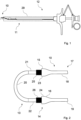
- the high-frequency tool 10 is arranged at a distal end of a shaft 11 of a resectoscope 12.
- a resectoscope 12 An example of an HF resectoscope 12 or a transporter of an HF resectoscope 12 with an indicated outer shaft 29 is shown.
- the high-frequency tool 10 is located in the Fig. 1 in a working position pushed out of the outer shaft 29.
- the high-frequency tool 10 shown is embodied, by way of example, as a cutting electrode having a cutting loop.
- the present invention is not limited to the exemplary embodiment of a resectoscope 12 or a cutting electrode shown here. Rather, the high-frequency tool 10 according to the invention can be used for any medical instrument.
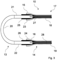
- FIG. 2 is an enlarged detail of the high-frequency tool 10 according to the invention.
- This high-frequency tool 10 essentially consists of a bow-shaped electrode 13 and the electrode carrier 14.
- the electrode carrier 14 is represented by a forked tube 17, also only partially shown.
- the forked tube 17 has two tubular arms 18, 19 that converge into a tube; together they form the electrode carrier 14.
- the electrode 13 shown here has an arc 20 or bow that extends downward into the plane of the drawing.
- this arc 20 is designed as a simple connection of the ends 21 and 22 and lies in the same plane as these.
- the design of the arc 20 allows the cutting depth or cutting pattern of the electrode 13 to be determined.
- the ends 21, 22 are each inserted into an opening or widened portion 23, 24 at the ends 15, 16 of the electrode carrier 14. Since both the electrode 13 and the arms 18, 19 of the fork tube 17 or of the electrode carrier 14 can be metallic, the likewise metallic electrode 13 or the ends 21, 22 of the electrode 13 must be insulated from the widened portions 23, 24.
- the invention provides for both the end 21 and the end 22 to be sheathed with an insulating tube 25, 26.
- This insulating tube 25, 26 can be, for example, a plastic tube or a PTFE tube.
- the wall thickness of this hose can be 0.1 mm to 0.5 mm or 0.2 mm to 0.4 mm, in particular 0.3 mm, whereby the wall thickness depends primarily on the material and the required dielectric strength.
- the ends 21, 22 of the electrode 14 are each firmly connected to a conductor wire 27, 28.
- This fixed connection between the ends 21, 22 and the conductor wires 27, 28 can be a crimp, solder, plug connection, or the like.
- the conductor wires 27, 28 are also electrically insulated by insulation against the walls of the arms 18, 19. This insulation can be, as in the Fig. 3 As shown, these are the same insulating tubes 25, 26 that also electrically insulate the ends 21, 22. The insulating tubes 25, 26 then converge to form a single insulating tube.
- the high-frequency tool 10 is inserted with its ends 21, 22 into the widened portions 23, 24 in such a way that the ends 21, 22, together with the insulating tubes 25, 26, form a virtually rigid connection with the widened portions 23, 24.
- This plug-in connection between the electrode 13 and the conductor wires 27, 28 makes the high-frequency tool 10 according to the invention stable against transverse forces. This means that when a force is applied transversely to the longitudinal axis of the resectoscope 12, in particular the widened portions 23, 24 of the electrode carrier 17 and the electrode 13 are not mechanically damaged.
- Fig. 2 and 3 illustrated shapes of the arms 18, 19 or the widened portions 23, 24 of the electrode carrier 17 are designed differently.
- the invention provides that instead of the insulating tubes 25, 26 or in addition to the insulating tubes 25, 26, the ends 21, 22 of the electrode 14 are insulated from the electrode carrier 17 by further or alternative insulators, such as PEEK tubes.
Landscapes
- Health & Medical Sciences (AREA)
- Surgery (AREA)
- Engineering & Computer Science (AREA)
- Life Sciences & Earth Sciences (AREA)
- Biomedical Technology (AREA)
- Otolaryngology (AREA)
- Nuclear Medicine, Radiotherapy & Molecular Imaging (AREA)
- Plasma & Fusion (AREA)
- Physics & Mathematics (AREA)
- Heart & Thoracic Surgery (AREA)
- Medical Informatics (AREA)
- Molecular Biology (AREA)
- Animal Behavior & Ethology (AREA)
- General Health & Medical Sciences (AREA)
- Public Health (AREA)
- Veterinary Medicine (AREA)
- Surgical Instruments (AREA)
Claims (8)
- Outil à haute fréquence (10), notamment électrode de coupe, pour des résectoscopes médicaux (12) destiné à la manipulation de tissus corporels, comprenant un porte-électrode (14) mobile dans la direction axiale du résectoscope (12), aux extrémités distales en forme de fourche duquel (15, 16) est maintenue une électrode (13) pouvant être soumise à un courant à haute fréquence, l'électrode (13) possédant deux extrémités (21, 22) qui, pour l'établissement d'une liaison avec le porte-électrode (14), sont respectivement situées dans ou, vues dans la direction distale, devant une ouverture de réception des extrémités (15, 16) du porte-électrode (14) et l'électrode (13) étant mise en en contact de manière électriquement conductrice, au moins dans une zone autour d'une ouverture de réception, avec un fil conducteur (27, 28) guidé dans le porte-électrode (14), dont la section transversale est inférieure à la section transversale de l'électrode (13), et les extrémités (15, 16) du porte-électrode (14) étant réalisées sous la forme d'élargissements (23, 24) servant à recevoir les extrémités (21, 22) de l'électrode (13),
caractérisé en ce que
l'électrode (13) et le fil conducteur (27, 28) sont réalisés d'une seule pièce en un matériau électriquement conducteur, l'électrode (13) représentant une zone du fil conducteur (27, 28) avec une section transversale agrandie, et le fil conducteur (27, 28) étant réalisé de manière continue et l'électrode (13) étant guidée sous forme de tube entre les extrémités (15, 16) du porte-électrode (14) au-dessus du fil conducteur (27, 28). - Outil à haute fréquence (10) selon la revendication 1, caractérisé en ce que les extrémités de l'électrode (13) sont enrobées d'un matériau de construction dont la résistance est supérieure à 80 MPa.
- Outil à haute fréquence (10) selon l'une des revendications précédentes, caractérisé en ce que les extrémités (21, 22) de l'électrode (13) et/ou les fils conducteurs (27, 28) sont enrobés d'un isolant, de préférence d'une gaine isolante (25, 26), notamment d'une gaine en matière plastique.
- Outil à haute fréquence (10) selon l'une des revendications précédentes, caractérisé en ce que les extrémités (21, 22) de l'électrode (13) sont respectivement isolées électriquement des extrémités (15, 16) du porte-électrode (14) par des petits tubes en PEEK ou des petits tubes en PPS.
- Outil à haute fréquence (10) selon l'une des revendications précédentes, caractérisé en ce que l'isolation des extrémités (21, 22) de l'électrode (13) et des fils conducteurs (27, 28) est réalisée d'une seule pièce, se compose de préférence de plusieurs pièces.
- Outil à haute fréquence (10) selon l'une des revendications précédentes, caractérisé en ce que les extrémités (21, 22) de l'électrode (13) enrobées par l'isolant sont reliées à demeure, notamment par sertissage, collage ou similaire, dans les élargissements (23, 24) du porte-électrode (14).
- Outil à haute fréquence (10) selon l'une des revendications précédentes, caractérisé en ce que les extrémités (21, 22) de l'électrode (13) peuvent être enfichées, en vue de la stabilisation, à travers des petits tubes en acier qui sont disposés directement devant les ouvertures de réception du porte-électrode (14).
- Outil à haute fréquence (10) selon la revendication 7,
caractérisé en ce que les petits tubes font partie intégrante de l'électrode (13) ou des extrémités (15, 16) du porte-électrode (14).
Applications Claiming Priority (2)
| Application Number | Priority Date | Filing Date | Title |
|---|---|---|---|
| DE102015014088.4A DE102015014088A1 (de) | 2015-11-03 | 2015-11-03 | Hochfrequenzwerkzeug für medizinische Resektoskope |
| PCT/EP2016/075856 WO2017076721A1 (fr) | 2015-11-03 | 2016-10-26 | Outil à haute fréquence pour résectoscope médical |
Publications (2)
| Publication Number | Publication Date |
|---|---|
| EP3310285A1 EP3310285A1 (fr) | 2018-04-25 |
| EP3310285B1 true EP3310285B1 (fr) | 2025-04-02 |
Family
ID=57206295
Family Applications (1)
| Application Number | Title | Priority Date | Filing Date |
|---|---|---|---|
| EP16787453.6A Active EP3310285B1 (fr) | 2015-11-03 | 2016-10-26 | Outil à haute fréquence pour résectoscope médical |
Country Status (6)
| Country | Link |
|---|---|
| US (1) | US11185365B2 (fr) |
| EP (1) | EP3310285B1 (fr) |
| JP (1) | JP6990651B2 (fr) |
| CN (1) | CN108348287B (fr) |
| DE (1) | DE102015014088A1 (fr) |
| WO (1) | WO2017076721A1 (fr) |
Families Citing this family (5)
| Publication number | Priority date | Publication date | Assignee | Title |
|---|---|---|---|---|
| CN113473930B (zh) * | 2018-12-14 | 2024-12-27 | 奥林巴斯株式会社 | 电极单元以及内窥镜系统 |
| DE102021100996B4 (de) | 2021-01-19 | 2023-03-16 | Olympus Winter & Ibe Gmbh | Elektrodeninstrument für ein Resektoskop und Resektoskop |
| DE102021109175B4 (de) | 2021-04-13 | 2024-10-24 | Olympus Winter & Ibe Gmbh | Elektrodeninstrument, chirurgisches Handgerät und deren Herstellungsverfahren |
| EP4119080A1 (fr) | 2021-07-12 | 2023-01-18 | Erbe Elektromedizin GmbH | Sonde plasma et procédé de montage de son électrode |
| DE102024103121A1 (de) * | 2024-02-05 | 2025-08-07 | Olympus Winter & Ibe Gmbh | Elektrochirurgisches Handinstrument und Elektrode für ein elektrochirurgisches Handinstrument |
Citations (1)
| Publication number | Priority date | Publication date | Assignee | Title |
|---|---|---|---|---|
| DE102005042312A1 (de) * | 2004-09-06 | 2006-03-09 | Pentax Corp. | Hochfrequenz-Behandlungsinstrument für ein Endoskop |
Family Cites Families (14)
| Publication number | Priority date | Publication date | Assignee | Title |
|---|---|---|---|---|
| US2965790A (en) * | 1949-08-20 | 1960-12-20 | Patent Treuhand Ges Fuer Elektrische Gluehlampen Mbh | High pressure gas lamp |
| JPS62122651A (ja) * | 1985-11-22 | 1987-06-03 | オリンパス光学工業株式会社 | 回転切除型のレゼクトスコ−プ |
| DE3834230A1 (de) * | 1987-10-07 | 1989-04-27 | Olympus Optical Co | Resektoskop |
| US6033400A (en) * | 1996-04-19 | 2000-03-07 | Circon Corporation | Shaped electrode for a resectoscope |
| US5919189A (en) | 1996-05-21 | 1999-07-06 | Benderev; Theodore V. | Electrosurgical instrument and method of use |
| JPH10295701A (ja) | 1997-04-25 | 1998-11-10 | Olympus Optical Co Ltd | レゼクトスコープ |
| EP1072230A1 (fr) | 1999-07-26 | 2001-01-31 | Ethicon, Inc. | Electrode bipolaire pour resection et coagulation |
| JP3967515B2 (ja) * | 2000-02-16 | 2007-08-29 | 株式会社神戸製鋼所 | マフラー用チタン合金材およびマフラー |
| US7704249B2 (en) * | 2004-05-07 | 2010-04-27 | Arthrocare Corporation | Apparatus and methods for electrosurgical ablation and resection of target tissue |
| DE202005021033U1 (de) * | 2005-07-12 | 2007-03-08 | Olympus Winter & Ibe Gmbh | Elektrodeneinheit für urologische Resektoskope |
| US8177784B2 (en) * | 2006-09-27 | 2012-05-15 | Electromedical Associates, Llc | Electrosurgical device having floating potential electrode and adapted for use with a resectoscope |
| US10736689B2 (en) * | 2008-08-20 | 2020-08-11 | Prostacare Pty Ltd | Low-corrosion electrode for treating tissue |
| US9888954B2 (en) * | 2012-08-10 | 2018-02-13 | Cook Medical Technologies Llc | Plasma resection electrode |
| CN102846375B (zh) * | 2012-08-16 | 2016-02-03 | 珠海市司迈科技有限公司 | 电切镜双极电极 |
-
2015
- 2015-11-03 DE DE102015014088.4A patent/DE102015014088A1/de active Pending
-
2016
- 2016-10-26 US US15/754,570 patent/US11185365B2/en active Active
- 2016-10-26 CN CN201680062658.2A patent/CN108348287B/zh active Active
- 2016-10-26 EP EP16787453.6A patent/EP3310285B1/fr active Active
- 2016-10-26 JP JP2018521046A patent/JP6990651B2/ja active Active
- 2016-10-26 WO PCT/EP2016/075856 patent/WO2017076721A1/fr not_active Ceased
Patent Citations (1)
| Publication number | Priority date | Publication date | Assignee | Title |
|---|---|---|---|---|
| DE102005042312A1 (de) * | 2004-09-06 | 2006-03-09 | Pentax Corp. | Hochfrequenz-Behandlungsinstrument für ein Endoskop |
Also Published As
| Publication number | Publication date |
|---|---|
| WO2017076721A1 (fr) | 2017-05-11 |
| DE102015014088A1 (de) | 2017-05-04 |
| US20180235688A1 (en) | 2018-08-23 |
| CN108348287A (zh) | 2018-07-31 |
| JP6990651B2 (ja) | 2022-01-12 |
| JP2018534053A (ja) | 2018-11-22 |
| US11185365B2 (en) | 2021-11-30 |
| CN108348287B (zh) | 2021-02-19 |
| EP3310285A1 (fr) | 2018-04-25 |
Similar Documents
| Publication | Publication Date | Title |
|---|---|---|
| EP1153578B1 (fr) | Instrument chirurgical en forme de pince ou de ciseaux | |
| DE102007053359B3 (de) | Chirurgisches Instrument | |
| DE19729461C1 (de) | Bipolares endoskopisches Instrument | |
| EP3437581B1 (fr) | Unité d'électrode pour un résectoscope médical | |
| EP3310285A1 (fr) | Outil à haute fréquence pour résectoscope médical | |
| DE10327237A1 (de) | Elektrochirurgisches Instrument für ein Endoskop | |
| DE20002645U1 (de) | Medizinisches bipolares Instrument zum Schneiden von Gewebe | |
| EP2243437B1 (fr) | Appareil d'hystérectomie doté d'un manipulateur d'utérus | |
| DE19847852A1 (de) | Endoskopisches Behandlungsinstrument | |
| EP3649974B1 (fr) | Agencement d'électrodes pour un résectoscope bipolaire et résectoscope | |
| DE202011000800U1 (de) | Chirurgisches Instrument | |
| DE19849974A1 (de) | Endoskopisches Einführinstrument | |
| DE102020130716A1 (de) | Verbindungsvorrichtung und monopolares Kabel für monopolar und bipolar betreibbare chirurgische Instrumente, chirurgisches Instrument und chirurgisches System | |
| EP2228027B1 (fr) | Appareil chirurgical haute fréquence | |
| DE102021100996B4 (de) | Elektrodeninstrument für ein Resektoskop und Resektoskop | |
| WO2013087132A1 (fr) | Résectoscope à tige | |
| DE102021109175B4 (de) | Elektrodeninstrument, chirurgisches Handgerät und deren Herstellungsverfahren | |
| DE102011105404B4 (de) | Chirurgisches Instrument für die Elektrotomie | |
| DE202007015547U1 (de) | Chirurgisches Instrument | |
| DE4237321C2 (de) | Instrument für die Hochfrequenzchirurgie | |
| DE10205093B4 (de) | Bipolare Klemme | |
| EP2537481A1 (fr) | Insert de travail pour un instrument endoscopique à tige creuse | |
| EP3471642B1 (fr) | Instrument chirurgical pour la diathermie chirurgicale et accessoire pour celui-ci | |
| DE102015004328B4 (de) | Transporteur und Stecker eines Resektoskopes | |
| DE102007001751B4 (de) | Elektrochirurgisches Verbindungsglied und elektrochirurgisches Instrument |
Legal Events
| Date | Code | Title | Description |
|---|---|---|---|
| STAA | Information on the status of an ep patent application or granted ep patent |
Free format text: STATUS: UNKNOWN |
|
| STAA | Information on the status of an ep patent application or granted ep patent |
Free format text: STATUS: THE INTERNATIONAL PUBLICATION HAS BEEN MADE |
|
| PUAI | Public reference made under article 153(3) epc to a published international application that has entered the european phase |
Free format text: ORIGINAL CODE: 0009012 |
|
| STAA | Information on the status of an ep patent application or granted ep patent |
Free format text: STATUS: REQUEST FOR EXAMINATION WAS MADE |
|
| 17P | Request for examination filed |
Effective date: 20180122 |
|
| AK | Designated contracting states |
Kind code of ref document: A1 Designated state(s): AL AT BE BG CH CY CZ DE DK EE ES FI FR GB GR HR HU IE IS IT LI LT LU LV MC MK MT NL NO PL PT RO RS SE SI SK SM TR |
|
| AX | Request for extension of the european patent |
Extension state: BA ME |
|
| RIN1 | Information on inventor provided before grant (corrected) |
Inventor name: KAISER, ANDREAS Inventor name: BROCKMANN, CHRISTIAN |
|
| DAV | Request for validation of the european patent (deleted) | ||
| DAX | Request for extension of the european patent (deleted) | ||
| STAA | Information on the status of an ep patent application or granted ep patent |
Free format text: STATUS: EXAMINATION IS IN PROGRESS |
|
| 17Q | First examination report despatched |
Effective date: 20210930 |
|
| GRAP | Despatch of communication of intention to grant a patent |
Free format text: ORIGINAL CODE: EPIDOSNIGR1 |
|
| STAA | Information on the status of an ep patent application or granted ep patent |
Free format text: STATUS: GRANT OF PATENT IS INTENDED |
|
| GRAS | Grant fee paid |
Free format text: ORIGINAL CODE: EPIDOSNIGR3 |
|
| INTG | Intention to grant announced |
Effective date: 20241107 |
|
| GRAA | (expected) grant |
Free format text: ORIGINAL CODE: 0009210 |
|
| STAA | Information on the status of an ep patent application or granted ep patent |
Free format text: STATUS: THE PATENT HAS BEEN GRANTED |
|
| AK | Designated contracting states |
Kind code of ref document: B1 Designated state(s): AL AT BE BG CH CY CZ DE DK EE ES FI FR GB GR HR HU IE IS IT LI LT LU LV MC MK MT NL NO PL PT RO RS SE SI SK SM TR |
|
| REG | Reference to a national code |
Ref country code: GB Ref legal event code: FG4D Free format text: NOT ENGLISH |
|
| REG | Reference to a national code |
Ref country code: CH Ref legal event code: EP |
|
| P01 | Opt-out of the competence of the unified patent court (upc) registered |
Free format text: CASE NUMBER: APP_12127/2025 Effective date: 20250312 |
|
| REG | Reference to a national code |
Ref country code: IE Ref legal event code: FG4D Free format text: LANGUAGE OF EP DOCUMENT: GERMAN |
|
| REG | Reference to a national code |
Ref country code: DE Ref legal event code: R096 Ref document number: 502016016941 Country of ref document: DE |
|
| REG | Reference to a national code |
Ref country code: NL Ref legal event code: MP Effective date: 20250402 |
|
| PG25 | Lapsed in a contracting state [announced via postgrant information from national office to epo] |
Ref country code: NL Free format text: LAPSE BECAUSE OF FAILURE TO SUBMIT A TRANSLATION OF THE DESCRIPTION OR TO PAY THE FEE WITHIN THE PRESCRIBED TIME-LIMIT Effective date: 20250402 |
|
| PG25 | Lapsed in a contracting state [announced via postgrant information from national office to epo] |
Ref country code: ES Free format text: LAPSE BECAUSE OF FAILURE TO SUBMIT A TRANSLATION OF THE DESCRIPTION OR TO PAY THE FEE WITHIN THE PRESCRIBED TIME-LIMIT Effective date: 20250402 Ref country code: PT Free format text: LAPSE BECAUSE OF FAILURE TO SUBMIT A TRANSLATION OF THE DESCRIPTION OR TO PAY THE FEE WITHIN THE PRESCRIBED TIME-LIMIT Effective date: 20250804 Ref country code: FI Free format text: LAPSE BECAUSE OF FAILURE TO SUBMIT A TRANSLATION OF THE DESCRIPTION OR TO PAY THE FEE WITHIN THE PRESCRIBED TIME-LIMIT Effective date: 20250402 |
|
| REG | Reference to a national code |
Ref country code: LT Ref legal event code: MG9D |
|
| PG25 | Lapsed in a contracting state [announced via postgrant information from national office to epo] |
Ref country code: GR Free format text: LAPSE BECAUSE OF FAILURE TO SUBMIT A TRANSLATION OF THE DESCRIPTION OR TO PAY THE FEE WITHIN THE PRESCRIBED TIME-LIMIT Effective date: 20250703 Ref country code: NO Free format text: LAPSE BECAUSE OF FAILURE TO SUBMIT A TRANSLATION OF THE DESCRIPTION OR TO PAY THE FEE WITHIN THE PRESCRIBED TIME-LIMIT Effective date: 20250702 |
|
| PG25 | Lapsed in a contracting state [announced via postgrant information from national office to epo] |
Ref country code: PL Free format text: LAPSE BECAUSE OF FAILURE TO SUBMIT A TRANSLATION OF THE DESCRIPTION OR TO PAY THE FEE WITHIN THE PRESCRIBED TIME-LIMIT Effective date: 20250402 |
|
| PG25 | Lapsed in a contracting state [announced via postgrant information from national office to epo] |
Ref country code: BG Free format text: LAPSE BECAUSE OF FAILURE TO SUBMIT A TRANSLATION OF THE DESCRIPTION OR TO PAY THE FEE WITHIN THE PRESCRIBED TIME-LIMIT Effective date: 20250402 |
|
| PGFP | Annual fee paid to national office [announced via postgrant information from national office to epo] |
Ref country code: GB Payment date: 20250904 Year of fee payment: 10 |
|
| PG25 | Lapsed in a contracting state [announced via postgrant information from national office to epo] |
Ref country code: HR Free format text: LAPSE BECAUSE OF FAILURE TO SUBMIT A TRANSLATION OF THE DESCRIPTION OR TO PAY THE FEE WITHIN THE PRESCRIBED TIME-LIMIT Effective date: 20250402 |
|
| PGFP | Annual fee paid to national office [announced via postgrant information from national office to epo] |
Ref country code: FR Payment date: 20250908 Year of fee payment: 10 |
|
| PG25 | Lapsed in a contracting state [announced via postgrant information from national office to epo] |
Ref country code: RS Free format text: LAPSE BECAUSE OF FAILURE TO SUBMIT A TRANSLATION OF THE DESCRIPTION OR TO PAY THE FEE WITHIN THE PRESCRIBED TIME-LIMIT Effective date: 20250702 |
|
| PG25 | Lapsed in a contracting state [announced via postgrant information from national office to epo] |
Ref country code: IS Free format text: LAPSE BECAUSE OF FAILURE TO SUBMIT A TRANSLATION OF THE DESCRIPTION OR TO PAY THE FEE WITHIN THE PRESCRIBED TIME-LIMIT Effective date: 20250802 |
|
| PG25 | Lapsed in a contracting state [announced via postgrant information from national office to epo] |
Ref country code: LV Free format text: LAPSE BECAUSE OF FAILURE TO SUBMIT A TRANSLATION OF THE DESCRIPTION OR TO PAY THE FEE WITHIN THE PRESCRIBED TIME-LIMIT Effective date: 20250402 |
|
| REG | Reference to a national code |
Ref country code: DE Ref legal event code: R097 Ref document number: 502016016941 Country of ref document: DE |
|
| PGFP | Annual fee paid to national office [announced via postgrant information from national office to epo] |
Ref country code: DE Payment date: 20250902 Year of fee payment: 10 |
|
| PG25 | Lapsed in a contracting state [announced via postgrant information from national office to epo] |
Ref country code: SM Free format text: LAPSE BECAUSE OF FAILURE TO SUBMIT A TRANSLATION OF THE DESCRIPTION OR TO PAY THE FEE WITHIN THE PRESCRIBED TIME-LIMIT Effective date: 20250402 Ref country code: DK Free format text: LAPSE BECAUSE OF FAILURE TO SUBMIT A TRANSLATION OF THE DESCRIPTION OR TO PAY THE FEE WITHIN THE PRESCRIBED TIME-LIMIT Effective date: 20250402 |
|
| PG25 | Lapsed in a contracting state [announced via postgrant information from national office to epo] |
Ref country code: CZ Free format text: LAPSE BECAUSE OF FAILURE TO SUBMIT A TRANSLATION OF THE DESCRIPTION OR TO PAY THE FEE WITHIN THE PRESCRIBED TIME-LIMIT Effective date: 20250402 |
|
| PG25 | Lapsed in a contracting state [announced via postgrant information from national office to epo] |
Ref country code: EE Free format text: LAPSE BECAUSE OF FAILURE TO SUBMIT A TRANSLATION OF THE DESCRIPTION OR TO PAY THE FEE WITHIN THE PRESCRIBED TIME-LIMIT Effective date: 20250402 |
|
| PG25 | Lapsed in a contracting state [announced via postgrant information from national office to epo] |
Ref country code: RO Free format text: LAPSE BECAUSE OF FAILURE TO SUBMIT A TRANSLATION OF THE DESCRIPTION OR TO PAY THE FEE WITHIN THE PRESCRIBED TIME-LIMIT Effective date: 20250402 Ref country code: SK Free format text: LAPSE BECAUSE OF FAILURE TO SUBMIT A TRANSLATION OF THE DESCRIPTION OR TO PAY THE FEE WITHIN THE PRESCRIBED TIME-LIMIT Effective date: 20250402 |
|
| PG25 | Lapsed in a contracting state [announced via postgrant information from national office to epo] |
Ref country code: IT Free format text: LAPSE BECAUSE OF FAILURE TO SUBMIT A TRANSLATION OF THE DESCRIPTION OR TO PAY THE FEE WITHIN THE PRESCRIBED TIME-LIMIT Effective date: 20250402 |
|
| PLBE | No opposition filed within time limit |
Free format text: ORIGINAL CODE: 0009261 |
|
| STAA | Information on the status of an ep patent application or granted ep patent |
Free format text: STATUS: NO OPPOSITION FILED WITHIN TIME LIMIT |
|
| REG | Reference to a national code |
Ref country code: CH Ref legal event code: L10 Free format text: ST27 STATUS EVENT CODE: U-0-0-L10-L00 (AS PROVIDED BY THE NATIONAL OFFICE) Effective date: 20260211 |
|
| 26N | No opposition filed |
Effective date: 20260105 |