EP3309887B1 - Fuel cell system and method of running fuel cell system - Google Patents
Fuel cell system and method of running fuel cell system Download PDFInfo
- Publication number
- EP3309887B1 EP3309887B1 EP17195882.0A EP17195882A EP3309887B1 EP 3309887 B1 EP3309887 B1 EP 3309887B1 EP 17195882 A EP17195882 A EP 17195882A EP 3309887 B1 EP3309887 B1 EP 3309887B1
- Authority
- EP
- European Patent Office
- Prior art keywords
- fuel cell
- temperature
- cell system
- combustor
- cathode
- Prior art date
- Legal status (The legal status is an assumption and is not a legal conclusion. Google has not performed a legal analysis and makes no representation as to the accuracy of the status listed.)
- Active
Links
- 239000000446 fuel Substances 0.000 title claims description 274
- 238000000034 method Methods 0.000 title claims description 33
- 239000007789 gas Substances 0.000 claims description 196
- 238000002485 combustion reaction Methods 0.000 claims description 155
- UFHFLCQGNIYNRP-UHFFFAOYSA-N Hydrogen Chemical compound [H][H] UFHFLCQGNIYNRP-UHFFFAOYSA-N 0.000 claims description 94
- 229910052739 hydrogen Inorganic materials 0.000 claims description 87
- 239000001257 hydrogen Substances 0.000 claims description 87
- XLYOFNOQVPJJNP-UHFFFAOYSA-N water Substances O XLYOFNOQVPJJNP-UHFFFAOYSA-N 0.000 claims description 72
- 239000000463 material Substances 0.000 claims description 51
- 230000003247 decreasing effect Effects 0.000 claims description 30
- 239000007787 solid Substances 0.000 claims description 11
- 238000000629 steam reforming Methods 0.000 claims description 6
- 230000004048 modification Effects 0.000 description 23
- 238000012986 modification Methods 0.000 description 23
- 238000010248 power generation Methods 0.000 description 23
- 238000001704 evaporation Methods 0.000 description 20
- 230000008020 evaporation Effects 0.000 description 20
- 239000003054 catalyst Substances 0.000 description 17
- 238000002407 reforming Methods 0.000 description 15
- UGFAIRIUMAVXCW-UHFFFAOYSA-N Carbon monoxide Chemical compound [O+]#[C-] UGFAIRIUMAVXCW-UHFFFAOYSA-N 0.000 description 12
- 229910002091 carbon monoxide Inorganic materials 0.000 description 12
- 238000006057 reforming reaction Methods 0.000 description 12
- 239000003792 electrolyte Substances 0.000 description 10
- 230000008901 benefit Effects 0.000 description 9
- VNWKTOKETHGBQD-UHFFFAOYSA-N methane Chemical compound C VNWKTOKETHGBQD-UHFFFAOYSA-N 0.000 description 8
- 230000002401 inhibitory effect Effects 0.000 description 7
- 230000008859 change Effects 0.000 description 6
- 238000006243 chemical reaction Methods 0.000 description 6
- 239000000919 ceramic Substances 0.000 description 5
- 238000010586 diagram Methods 0.000 description 4
- 230000004913 activation Effects 0.000 description 3
- 239000012530 fluid Substances 0.000 description 3
- 230000005484 gravity Effects 0.000 description 3
- 239000003915 liquefied petroleum gas Substances 0.000 description 3
- PXHVJJICTQNCMI-UHFFFAOYSA-N Nickel Chemical compound [Ni] PXHVJJICTQNCMI-UHFFFAOYSA-N 0.000 description 2
- KJTLSVCANCCWHF-UHFFFAOYSA-N Ruthenium Chemical compound [Ru] KJTLSVCANCCWHF-UHFFFAOYSA-N 0.000 description 2
- 230000015556 catabolic process Effects 0.000 description 2
- 238000006731 degradation reaction Methods 0.000 description 2
- 230000006870 function Effects 0.000 description 2
- 150000002431 hydrogen Chemical class 0.000 description 2
- 230000007774 longterm Effects 0.000 description 2
- 239000003345 natural gas Substances 0.000 description 2
- 230000002093 peripheral effect Effects 0.000 description 2
- BASFCYQUMIYNBI-UHFFFAOYSA-N platinum Chemical compound [Pt] BASFCYQUMIYNBI-UHFFFAOYSA-N 0.000 description 2
- 229910052707 ruthenium Inorganic materials 0.000 description 2
- 230000000087 stabilizing effect Effects 0.000 description 2
- 239000007858 starting material Substances 0.000 description 2
- 230000008646 thermal stress Effects 0.000 description 2
- OKTJSMMVPCPJKN-UHFFFAOYSA-N Carbon Chemical compound [C] OKTJSMMVPCPJKN-UHFFFAOYSA-N 0.000 description 1
- 239000004215 Carbon black (E152) Substances 0.000 description 1
- 238000002453 autothermal reforming Methods 0.000 description 1
- 229910052799 carbon Inorganic materials 0.000 description 1
- 150000001875 compounds Chemical class 0.000 description 1
- 238000004590 computer program Methods 0.000 description 1
- 238000005336 cracking Methods 0.000 description 1
- 230000000593 degrading effect Effects 0.000 description 1
- 230000001419 dependent effect Effects 0.000 description 1
- 230000000694 effects Effects 0.000 description 1
- 239000002737 fuel gas Substances 0.000 description 1
- 239000003502 gasoline Substances 0.000 description 1
- 238000010438 heat treatment Methods 0.000 description 1
- 229930195733 hydrocarbon Natural products 0.000 description 1
- 150000002430 hydrocarbons Chemical class 0.000 description 1
- 239000011810 insulating material Substances 0.000 description 1
- 239000003350 kerosene Substances 0.000 description 1
- 229910052759 nickel Inorganic materials 0.000 description 1
- 229910000510 noble metal Inorganic materials 0.000 description 1
- 229910052697 platinum Inorganic materials 0.000 description 1
- 230000008569 process Effects 0.000 description 1
- 229910052703 rhodium Inorganic materials 0.000 description 1
- 239000010948 rhodium Substances 0.000 description 1
- MHOVAHRLVXNVSD-UHFFFAOYSA-N rhodium atom Chemical compound [Rh] MHOVAHRLVXNVSD-UHFFFAOYSA-N 0.000 description 1
- 238000000926 separation method Methods 0.000 description 1
- 238000011144 upstream manufacturing Methods 0.000 description 1
Images


Classifications
-
- H—ELECTRICITY
- H01—ELECTRIC ELEMENTS
- H01M—PROCESSES OR MEANS, e.g. BATTERIES, FOR THE DIRECT CONVERSION OF CHEMICAL ENERGY INTO ELECTRICAL ENERGY
- H01M8/00—Fuel cells; Manufacture thereof
- H01M8/04—Auxiliary arrangements, e.g. for control of pressure or for circulation of fluids
- H01M8/04007—Auxiliary arrangements, e.g. for control of pressure or for circulation of fluids related to heat exchange
- H01M8/04067—Heat exchange or temperature measuring elements, thermal insulation, e.g. heat pipes, heat pumps, fins
- H01M8/04074—Heat exchange unit structures specially adapted for fuel cell
-
- H—ELECTRICITY
- H01—ELECTRIC ELEMENTS
- H01M—PROCESSES OR MEANS, e.g. BATTERIES, FOR THE DIRECT CONVERSION OF CHEMICAL ENERGY INTO ELECTRICAL ENERGY
- H01M8/00—Fuel cells; Manufacture thereof
- H01M8/04—Auxiliary arrangements, e.g. for control of pressure or for circulation of fluids
- H01M8/04007—Auxiliary arrangements, e.g. for control of pressure or for circulation of fluids related to heat exchange
- H01M8/04014—Heat exchange using gaseous fluids; Heat exchange by combustion of reactants
- H01M8/04022—Heating by combustion
-
- H—ELECTRICITY
- H01—ELECTRIC ELEMENTS
- H01M—PROCESSES OR MEANS, e.g. BATTERIES, FOR THE DIRECT CONVERSION OF CHEMICAL ENERGY INTO ELECTRICAL ENERGY
- H01M8/00—Fuel cells; Manufacture thereof
- H01M8/04—Auxiliary arrangements, e.g. for control of pressure or for circulation of fluids
- H01M8/04082—Arrangements for control of reactant parameters, e.g. pressure or concentration
- H01M8/04089—Arrangements for control of reactant parameters, e.g. pressure or concentration of gaseous reactants
- H01M8/04119—Arrangements for control of reactant parameters, e.g. pressure or concentration of gaseous reactants with simultaneous supply or evacuation of electrolyte; Humidifying or dehumidifying
- H01M8/04156—Arrangements for control of reactant parameters, e.g. pressure or concentration of gaseous reactants with simultaneous supply or evacuation of electrolyte; Humidifying or dehumidifying with product water removal
-
- H—ELECTRICITY
- H01—ELECTRIC ELEMENTS
- H01M—PROCESSES OR MEANS, e.g. BATTERIES, FOR THE DIRECT CONVERSION OF CHEMICAL ENERGY INTO ELECTRICAL ENERGY
- H01M8/00—Fuel cells; Manufacture thereof
- H01M8/04—Auxiliary arrangements, e.g. for control of pressure or for circulation of fluids
- H01M8/04298—Processes for controlling fuel cells or fuel cell systems
- H01M8/04313—Processes for controlling fuel cells or fuel cell systems characterised by the detection or assessment of variables; characterised by the detection or assessment of failure or abnormal function
- H01M8/0432—Temperature; Ambient temperature
- H01M8/04335—Temperature; Ambient temperature of cathode reactants at the inlet or inside the fuel cell
-
- H—ELECTRICITY
- H01—ELECTRIC ELEMENTS
- H01M—PROCESSES OR MEANS, e.g. BATTERIES, FOR THE DIRECT CONVERSION OF CHEMICAL ENERGY INTO ELECTRICAL ENERGY
- H01M8/00—Fuel cells; Manufacture thereof
- H01M8/04—Auxiliary arrangements, e.g. for control of pressure or for circulation of fluids
- H01M8/04298—Processes for controlling fuel cells or fuel cell systems
- H01M8/04313—Processes for controlling fuel cells or fuel cell systems characterised by the detection or assessment of variables; characterised by the detection or assessment of failure or abnormal function
- H01M8/0432—Temperature; Ambient temperature
- H01M8/04373—Temperature; Ambient temperature of auxiliary devices, e.g. reformers, compressors, burners
-
- H—ELECTRICITY
- H01—ELECTRIC ELEMENTS
- H01M—PROCESSES OR MEANS, e.g. BATTERIES, FOR THE DIRECT CONVERSION OF CHEMICAL ENERGY INTO ELECTRICAL ENERGY
- H01M8/00—Fuel cells; Manufacture thereof
- H01M8/04—Auxiliary arrangements, e.g. for control of pressure or for circulation of fluids
- H01M8/04298—Processes for controlling fuel cells or fuel cell systems
- H01M8/04694—Processes for controlling fuel cells or fuel cell systems characterised by variables to be controlled
- H01M8/04701—Temperature
- H01M8/04708—Temperature of fuel cell reactants
-
- H—ELECTRICITY
- H01—ELECTRIC ELEMENTS
- H01M—PROCESSES OR MEANS, e.g. BATTERIES, FOR THE DIRECT CONVERSION OF CHEMICAL ENERGY INTO ELECTRICAL ENERGY
- H01M8/00—Fuel cells; Manufacture thereof
- H01M8/04—Auxiliary arrangements, e.g. for control of pressure or for circulation of fluids
- H01M8/04298—Processes for controlling fuel cells or fuel cell systems
- H01M8/04694—Processes for controlling fuel cells or fuel cell systems characterised by variables to be controlled
- H01M8/04746—Pressure; Flow
- H01M8/04753—Pressure; Flow of fuel cell reactants
-
- H—ELECTRICITY
- H01—ELECTRIC ELEMENTS
- H01M—PROCESSES OR MEANS, e.g. BATTERIES, FOR THE DIRECT CONVERSION OF CHEMICAL ENERGY INTO ELECTRICAL ENERGY
- H01M8/00—Fuel cells; Manufacture thereof
- H01M8/04—Auxiliary arrangements, e.g. for control of pressure or for circulation of fluids
- H01M8/04298—Processes for controlling fuel cells or fuel cell systems
- H01M8/04694—Processes for controlling fuel cells or fuel cell systems characterised by variables to be controlled
- H01M8/04746—Pressure; Flow
- H01M8/04776—Pressure; Flow at auxiliary devices, e.g. reformer, compressor, burner
-
- H—ELECTRICITY
- H01—ELECTRIC ELEMENTS
- H01M—PROCESSES OR MEANS, e.g. BATTERIES, FOR THE DIRECT CONVERSION OF CHEMICAL ENERGY INTO ELECTRICAL ENERGY
- H01M8/00—Fuel cells; Manufacture thereof
- H01M8/04—Auxiliary arrangements, e.g. for control of pressure or for circulation of fluids
- H01M8/04298—Processes for controlling fuel cells or fuel cell systems
- H01M8/04694—Processes for controlling fuel cells or fuel cell systems characterised by variables to be controlled
- H01M8/04858—Electric variables
- H01M8/04925—Power, energy, capacity or load
- H01M8/0494—Power, energy, capacity or load of fuel cell stacks
-
- H—ELECTRICITY
- H01—ELECTRIC ELEMENTS
- H01M—PROCESSES OR MEANS, e.g. BATTERIES, FOR THE DIRECT CONVERSION OF CHEMICAL ENERGY INTO ELECTRICAL ENERGY
- H01M8/00—Fuel cells; Manufacture thereof
- H01M8/06—Combination of fuel cells with means for production of reactants or for treatment of residues
- H01M8/0606—Combination of fuel cells with means for production of reactants or for treatment of residues with means for production of gaseous reactants
- H01M8/0612—Combination of fuel cells with means for production of reactants or for treatment of residues with means for production of gaseous reactants from carbon-containing material
- H01M8/0618—Reforming processes, e.g. autothermal, partial oxidation or steam reforming
-
- Y—GENERAL TAGGING OF NEW TECHNOLOGICAL DEVELOPMENTS; GENERAL TAGGING OF CROSS-SECTIONAL TECHNOLOGIES SPANNING OVER SEVERAL SECTIONS OF THE IPC; TECHNICAL SUBJECTS COVERED BY FORMER USPC CROSS-REFERENCE ART COLLECTIONS [XRACs] AND DIGESTS
- Y02—TECHNOLOGIES OR APPLICATIONS FOR MITIGATION OR ADAPTATION AGAINST CLIMATE CHANGE
- Y02E—REDUCTION OF GREENHOUSE GAS [GHG] EMISSIONS, RELATED TO ENERGY GENERATION, TRANSMISSION OR DISTRIBUTION
- Y02E60/00—Enabling technologies; Technologies with a potential or indirect contribution to GHG emissions mitigation
- Y02E60/30—Hydrogen technology
- Y02E60/50—Fuel cells
Definitions
- the present disclosure relates to a fuel cell system and a method of running a fuel cell system.
- Fuel cells enjoy high power generation efficiency despite their small size, and can boost their overall efficiency by using heat produced in power generation. Having these advantages, fuel cells are used as a power generator in a distributed power generation system. Particularly, solid oxide fuel cells (hereinafter also abbreviated to SOFC) using a solid oxide as an electrolyte and operating at high temperature are known to have high power generation efficiency.
- SOFC solid oxide fuel cells
- a fuel cell In order to make the distributed power generation system function, fuel gas needs to be stably supplied to the fuel cells during power generation.
- a fuel cell generates power by using fuel in the form of a hydrogen-containing gas obtained through a reforming reaction of material, such as natural gas consisting mainly of methane, liquefied petroleum gas (LPG), gasoline or kerosene, which is supplied from the existing infrastructure.
- the reforming reaction (endothermic reaction) needs to progress within a temperature range of about 550°C to 750°C.
- Heat needed for the reforming reaction is generally obtained through combustion of hydrogen-containing gas which is not used in the power generation by an SOFC.
- the SOFC operates at as high temperature as that in the reforming reaction. Accordingly, air not used for the power generation by the SOFC also has high temperature due to heat produced during the power generation.
- effective use of the thermal energy for the reaction related to the power generation realizes high-efficiency power generation.
- a structure integrally housing a fuel cell stack (a set of single fuel cells), a reformer and an air heat exchanger.
- the fuel cell stack is arranged in the center portion of the structure, and the reformer is arranged above the fuel cell stack.
- a structure further includes: a combustor, arranged above the fuel cell stack, for combusting hydrogen-containing gas (anode-off gas) and air (cathode-off gas) which have made no contribution to the power generating reaction in the fuel cell stack; and a combustion detector arranged above the combustor (see, for example, Japanese Unexamined Patent Application Publication No. 2010-67547 ).
- Patent Document 2 proposes, for example, a configuration in which: the fuel cell system includes a determination unit which determines whether a flameout occurs in the combustor; and the combustor is reignited with the flow rate of material or air controlled if the flameout is determined as occurring.
- EP 3 026 746 A1 relates to a method for operating a fuel cell system and US 2013/316256 A1 relates to a fuel cell system.
- Japanese Unexamined Patent Application Publication No. 2015-185213 only discloses the aforementioned control of the flow rate of gas to reignite the combustor after activation of a fuel cell system, and does not fully examine problems in the case where the combustor becomes an unstable combustion state while forming the flame.
- One non-limiting and exemplary embodiment provides a fuel cell system and a method of running a fuel cell system which are capable of making the combustion state of the combust more stable than ever while the combustor is forming the flame.
- a fuel cell system is defined in claim 1 and a method of running a fuel cell system is defined in claim 11.
- the fuel cell system and the method of running a fuel cell system of the aspect of the present disclosure have an advantageous effect of being able to make the combustion state of the combustor more stable than ever while the combustor is forming the flame. Further advantageous embodiments are defined in the dependent claims.
- a combustion state of a combustor is likely to become unstable because an anode-off gas and a cathode-off gas, which have made no contribution to the power generation by a fuel cell, burn in the combustor.
- the power generation by the fuel cell under high efficiency conditions requires an operation of increasing a ratio of hydrogen consumption by the anode of the fuel cell, and accordingly poses a risk that such a high-efficiency operation of the fuel cell system puts the combustor into lean burn which is close to a flameout area.
- the temperature of the solid oxide fuel cell drops rapidly.
- the electrolyte of the solid oxide fuel cell is made of ceramic, the rapid temperature change is likely to cause damage, such as heat cracking, on the electrolyte. This is a factor of degrading the fuel cell system.
- the degradation of the fuel cell system will lead to a decrease in the power generating performance of the fuel cell, and an impediment to high-efficiency operation of the fuel cell.
- the inventors have examined the combustion state of the combustor while the fuel cell system is in operation, and consequently found that in a combustion continuation area of the combustor from an normal combustion area up to the flameout area of the combustor, there exists an unstable area where the concentration of carbon monoxide in the combustion exhaust gas increases. Furthermore, the inventors have further found that the combustion temperature of the combustor and the concentration of carbon monoxide in the combustion exhaust gas have a correlation in the unstable area.
- one possible solution to the case where the combustion state of the combustor becomes unstable in the combustion continuation area up to the flameout area of the combustor is to stop the fuel cell system in accordance with a preset condition as is the case with activation of the fuel cell system.
- repeated operation of stopping the fuel cell system while the combustor is forming the flame has a risk that, as discussed above, the rapid change in the temperature of the solid oxide fuel cell will damage the electrolyte (ceramic) of the fuel cell, and disable the fuel cell system from continuing its normal operation.
- a fuel cell system of a first aspect of the present disclosure is devised based on findings described above, and defined in claim 1.
- a method of running a fuel cell system of the first aspect of the present disclosure is defined in claim 11.
- the fuel cell system and the method of running a fuel cell system of the aspect are capable of making the combustion state of the combustor more stable than ever while the combustor is forming the flame.
- the combustion state of the combustor can be improved while the combustor is continuing its combustion.
- the damage on the electrolyte (ceramic) which is caused by the rapid change in the temperature of the fuel cell can be more inhibited than ever. Accordingly, the durability of the fuel cell system can be improved.
- the first threshold is set in advance at a combustion temperature at which the combustor can keep the steady combustion state. Accordingly, if the temperature detected by the first temperature detector is lower than the first threshold although the combustor is forming the flame, at least one of the foregoing operations is performed.
- the combustor since the combustor combusts the anode-off gas discharged from the anode of the fuel cell and the cathode-off gas discharged from the cathode of the fuel cell, there is likelihood that the amount of cathode-off gas (air) sent to the combustor is greater than the amount of anode-off gas sent to the combustor. In this case, the combustion state of the combustor is more likely to get into an unstable lean-burn.
- the fuel cell system and the method of running a fuel cell system of the aspect perform the operation of increasing the ratio of the air consumed by the cathode of the fuel cell to the air supplied to the cathode of the fuel cell, and thereby can decrease the amount of cathode-off gas sent to the combustor.
- This decrease makes the amount of cathode-off gas smaller than the amount of anode-off gas.
- the system and the method perform the operation of decreasing the ratio of the hydrogen-containing gas consumed by the anode of the fuel cell to the hydrogen-containing gas supplied to the anode of the fuel cell, and thereby can increase the amount of anode-off gas sent to the combustor.
- This increase makes the amount of anode-off gas larger than the amount of cathode-off gas.
- the system and the method perform the operation of decreasing the amount of water supplied to the reformer, and thereby can decrease the amount of steam in the hydrogen-containing gas (hydrogen gas) sent from the reformer to the anode of the fuel cell.
- This decrease makes it possible to decrease the quantity of heat which the reformer needs from the combustion exhaust gas to evaporate the water, and thereby increases the amount of heat exchanged between the air in the air heat exchanger and the combustion exhaust gas.
- it is possible to raise the temperature of the air from the air heat exchanger to the fuel cell, and thus to raise the temperature of the fuel cell and the temperature of the cathode-off gas. This leads to a rise in the combustion temperature of the combustor, which makes it easy for the combustor to maintain the combustion reaction.
- the combustion state of the combustor can be improved while the combustor is continuing the combustion.
- the decrease in the amount of steam in the hydrogen-containing gas (hydrogen gas) sent from the reformer to the anode of the fuel cell makes it possible to increase the proportion of the hydrogen gas in the anode-off gas.
- the lean burn in which the combustion state of the combustor is unstable is eased, and the combustion temperature of the combustor rises. Accordingly, the combustion state of the combustor can be improved while the combustor is continuing the combustion.
- a fuel cell system of a second aspect of the present disclosure further may include an air supplier which supplies the air to the cathode of the fuel cell, in which as the operation of increasing the ratio of the air consumed by the cathode of the fuel cell to the air supplied to the cathode of the fuel cell, the controller controls the air supplier so as to decrease a flow rate of the air supplied to the cathode of the fuel cell.
- This configuration makes it possible for the foregoing operation to be appropriately performed by controlling how much to operate the air supplier.
- a fuel cell system of a third aspect of the present disclosure further may include a material supplier which supplies the material to the reformer, in which as the operation of decreasing the ratio of the hydrogen-containing gas consumed by the anode of the fuel cell to the hydrogen-containing gas supplied to the anode of the fuel cell, the controller controls the material supplier so as to increase a flow rate of the material supplied to the reformer.
- This configuration makes it possible for the foregoing operation to be appropriately performed by controlling how much to operate the material supplier.
- a controller may control the fuel cell system so as to decrease an amount of power generated by the fuel cell, as the operation of decreasing the ratio of the hydrogen-containing gas consumed by the anode of the fuel cell to the hydrogen-containing gas supplied to the anode of the fuel cell.
- This configuration makes it possible for the foregoing operation to be appropriately performed by controlling how much to operate the fuel cell system.
- a fuel cell system of a fifth aspect of the present disclosure further may include a water supplier which supplies the water to the reformer, in which the controller controls the water supplier so as to decrease a flow rate of the water supplied to the reformer.
- This configuration makes it possible for the foregoing operation to be appropriately performed by controlling how much to operate the water supplier.
- the first embodiment, the first and second examples of the first embodiment, the first and second modifications of the first embodiment, as well as the second embodiment which are described below represent examples of the above-discussed aspects. For this reason, shapes, materials, components, arrangement positions and connection modes of the components, steps of operations, sequences of the steps, and the like shown below only provide examples, and are not intended to limit the foregoing aspects unless specifically described in Claims. Any component which is included in the following components and is not recited in the independent Claims providing the most generic concept will be described as optional components. In addition, descriptions for components denoted by the same reference signs in the drawings will be omitted in some cases.
- drawings schematically illustrate the components in order to make the components easier to understand, and shapes of the components and dimensional ratios among the components are not exactly shown in some drawings.
- sequence of the steps in each operation may be changed depending on the necessity.
- other publicly-known steps may be added to the operation whenever deemed necessary.
- Fig. 1 is a diagram illustrating an example of a fuel cell system of a first embodiment.
- the fuel cell system 100 includes a solid oxide fuel cell 1 (hereinafter abbreviated to SOFC 1), a combustor 2, a reformer 4, an air heat exchanger 7, a material supplier 10, a water supplier 11, an air supplier 12, a hydrogen-containing gas supply route 13, an air supply route 14, an anode-off gas discharge route 15, a cathode-off gas discharge route 16, a flame guide 18, a controller 20 and a first temperature detector 21.
- SOFC 1 solid oxide fuel cell 1
- combustor 2 combustor 2
- reformer 4 an air heat exchanger 7
- material supplier 10 a water supplier 11
- an air supplier 12 a hydrogen-containing gas supply route 13
- an air supply route 14 an anode-off gas discharge route
- a cathode-off gas discharge route 16 a flame guide 18, a controller 20 and a first temperature detector 21.
- the reformer 4 By steam-reforming of a material, the reformer 4 generates a hydrogen-containing gas to be supplied to an anode of the SOFC 1.
- the reformer 4 includes: a cylinder inner wall 4A; a cylinder outer wall 4B; and a reforming catalyst 4C provided between the cylinder inner wall 4A and the cylinder outer wall 4B.
- the reforming catalyst 4C causes the material to undergo steam-reforming reaction, and thereby generates the hydrogen-containing reformed gas.
- the container of the reformer 4 is constructed from two cylinders which are the cylinder inner wall 4A and the cylinder outer wall 4B. Accordingly, while under a high-temperature condition, the thus-constructed container of the reformer 4 makes it possible for the reformer 4 to withstand thermal stress more appropriately and securely than if the container of the reformer 4 would be shaped like a rectangular cylinder.
- the reformer 4 may employ any type of reforming reaction.
- the reforming reaction include steam-reforming reaction, and autothermal reforming reaction.
- at least one selected from a group consisting of nickel and noble metal catalysts such as platinum, ruthenium and rhodium may be used for the reforming catalyst 4C.
- the stream-reforming reaction on the material is used as the reforming reaction to be performed by the reformer 4, and a catalyst containing ruthenium is used as the reforming catalyst 4C of the reformer 4.
- the material supplier 10 supplies the material to the reformer 4.
- the material supplier 10 may have any configuration as long as it is capable of supplying the material to the reformer 4.
- the material supplier 10 is a device which controls the flow rate of the material sent to the reformer 4, and may be formed, for example, from both or either of a pressure booster and a flow rate control valve.
- a constant-volume pump for example, may be used as the pressure booster.
- the pressure booster is not limited to the constant-volume pump.
- the material is supplied from a material supply source.
- the material supply source has a predetermined supply pressure. Examples of the material supply source include a material cylinder and a material infrastructure.
- the material is a hydrocarbon fuel containing an organic chemical compound made of at least carbon and hydrogen, such as methane-based town gas, natural gas or LPG.
- the water supplier 11 supplies the water to the reformer 4.
- the water supplier 11 may have any configuration as long as it is capable of supplying the water to the reformer 4.
- the water supplier 11 is a device which controls the flow rate of the water sent to the reformer 4, and may be formed, for example, from both or either of a pressure booster and a flow rate control valve.
- a constant-volume pump for example, may be used as the pressure booster.
- the pressure booster is not limited to the constant-volume pump.
- the reformer 4 includes a water evaporation unit 4D located above the reforming catalyst 4C, and formed by the cylinder inner wall 4A and the cylinder outer wall 4B.
- the lower portion of the container of the reformer 4 is filled with the reforming catalyst 4C, while the water evaporation unit 4D is formed in the upper portion of the container of the reformer 4.
- the water evaporation unit 4D which generates steam to be supplied to the reforming catalyst 4C can be more easily constructed than if the reformer 4 would include no water evaporation unit.
- the material from the material supplier 10 and the water from the water supplier 11 are sent to the water evaporation unit 4D.
- the material and the water are mixed together in the water evaporation unit 4D, and thereafter, the mixed gas is supplied to the reforming catalyst 4C.
- the water evaporation unit 4D may include a water receiving portion (not illustrated) which temporarily stores the water in the middle of the flow of the water in the water evaporation unit 4D, or a flow path member (not illustrated) which forms a helical flow path.
- the water receiving portion or the flow path member makes it possible to appropriately evaporate the water in the middle of the water evaporation unit 4D even when the water in the water evaporation unit 4D is dropped in a direction in which the gravity works.
- the fuel cell system 100 is further provided with devices such as a supplying device which supplies the reformer 4 with air for the reforming reaction.
- the air supplier 12 supplies air to a cathode of the SOFC 1.
- the air supplier 12 may have any configuration as long as it is capable of supplying the air to the cathode of the SOFC 1.
- the air supplier 12 is a device which controls the flow rate of the air sent to the cathode of the SOFC 1, and may be formed, for example, from a blower, a sirocco fan, or the like.
- the air supplier 12 is connected to the air heat exchanger 7.
- the air heat exchanger 7 includes a cylindrical inner wall 7A, a cylindrical outer wall 7B, and an air route 7C provided between the cylindrical inner wall 7A and the cylindrical outer wall 7B.
- the air heat exchanger 7 surrounds the reformer 4, and is arranged coaxially with the reformer 4.
- the container of the air heat exchanger 7 is constructed from two cylinders which are the cylindrical inner wall 7A and the cylindrical outer wall 7B.
- the inside of the container serves as a passage route of the air to be used as a heat receiving fluid of the air heat exchanger 7.
- the air heated by the air heat exchanger 7 is sent to the cathode of the SOFC 1, and is used for the SOFC 1's power generation.
- descriptions will be provided for the route of the combustion exhaust gas to be used as a heating fluid of the air heat exchanger 7.
- the external forms of the cylindrical inner wall 7A and the cylindrical outer wall 7B of the air heat exchanger 7 may be cylindrical or rectangularly cylindrical.
- An advantage of the cylindrical shape over the rectangularly cylindrical shape is that the cylindrical inner and outer walls 7A, 7B formed in the cylindrical shape is better in withstanding the thermal stress than the cylindrical inner and outer walls 7A, 7B formed in the rectangularly cylindrical shape.
- An advantage of the rectangularly cylindrical shape over the cylindrical shape is that the cylindrical inner and outer walls 7A, 7B formed in the rectangularly cylindrical shape makes it easier to cover the air exchanger 7 with a heat insulating material than the cylindrical inner and outer walls 7A, 7B formed in the cylindrical shape.
- the SOFC 1 generates power by using the air, supplied to the cathode, and the hydrogen-containing gas, supplied to the anode, as fuel. To put it specifically, the SOFC 1 generates the power by using: the hydrogen-containing gas generated by the reformer 4; and the air passing through the air heat exchanger 7.
- the SOFC 1 includes a fuel cell stack, which is not illustrated.
- the fuel cell stack is formed in a flat-plate shape by stacking members such as flat cells and interconnections. Incidentally, the shape of the fuel cell stack is limited to the flat plate.
- the anode-off gas discharge route 15 to be used to discharge the hydrogen-containing gas not used for the SOFC 1's power generation (anode-off gas) to the combustor 2 and the cathode-off gas discharge route 16 to be used to discharge the air not used for the SOFC 1's power generation (cathode-off gas) to the combustor 2 are connected to the respective appropriate portions of the SOFC 1.
- the combustor 2 combusts the anode-off gas discharged from the anode of the SOFC 1 and the cathode-off gas discharged from the cathode of the SOFC 1, and thereby generates the combustion exhaust gas.
- the anode-off gas and the cathode-off gas discharged from the SOFC 1 are sent to the combustor 2 via the anode-off gas discharge route 15 and the cathode-off gas discharge route 16, respectively.
- the gases are combusted in the combustor 2.
- the high-temperature combustion exhaust gas is generated in a combustion space 8 of the combustor 2.
- the combustor 2 is provided outside the SOFC 1.
- the anode-off gas discharge route 15 and the cathode-off gas discharge route 16 both extending from the SOFC 1 are connected to the respective appropriate portions of the combustor 2.
- a flame hole portion (not illustrated) is formed in the combustor 2.
- the cylindrical flame guide 18 is in contact with a bottom wall portion of the main container which houses the reformer 4, the air heat exchanger 7 and the like (for example, a wall portion of the combustor 2 where the flame hole portion is formed), and is provided vertically upright in a way that directs the flame guide 18 to the periphery of the combustion space 8.
- the SOFC 1 is provided at a position along the center axis of the reformer 4, and away from both the reformer 4 and the combustor 2.
- the reformer 4 is provided at a position along the center axis of the reformer 4, and away from the combustor 2.
- the cylinder inner wall 4A of the reformer 4 is arranged along the circumference of the combustion space 8 for the flame which is formed by the combustor 2.
- the reformer 4 (the combustion space 8), the combustor 2 and the SOFC 1 are arranged in this order in the up-to-down direction in which the gravity works, and with an appropriate separation distance between each neighboring two of them.
- a combustion exhaust gas route 9 of the combustor 2 is formed by a space between the flame guide 18 and the cylinder inner wall 4A of the reformer 4, a space between the lower end of the reformer 4 and the bottom wall portion of the main container, as well as a space between the cylinder outer wall 4B of the reformer 4 and the cylindrical inner wall 7A of the air heat exchanger 7.
- the combustion exhaust gas is guided downward along the flame guide 18 and the reformer 4, thereafter passes the space right under the lower end of the reformer 4, and is eventually guided upward along the reformer 4 and the air heat exchanger 7.
- the first temperature detector 21 detects at least one of the temperature of the combustion exhaust gas and the temperature of the combustor 2 (which may be also hereinafter referred to as the combustion temperature of the combustor 2 for the sake of convenience).
- the first temperature detector 21 may have any configuration as long as it is capable of detecting the combustion temperature of the combustor 2.
- the first temperature detector 21 may be provided at any place near the combustor 2.
- the first temperature detector 21 may be provided at an appropriate place in a space above the flame guide 18.
- the first temperature detector 21 may be provided at a place which the flame of the combustor 2 directly hits.
- the configuration may be such that the first temperature detector 21 detects the temperature of the flame which is formed by the combustor 2.
- the first temperature detector 21 may be provided on the combustion exhaust gas route 9 outside the flame guide 18, or at a predetermined place which correlates with the temperature of the combustion exhaust gas (for example, on the outer surface of the cylinder inner wall 4A forming the combustion exhaust gas route 9).
- the configuration may be such that the first temperature detector 21 detects the temperature of a high-temperature combustion exhaust gas which has just come out of the flame guide 18.
- the first temperature detector 21 is arranged on the combustion exhaust gas route 9 near the outer surface of the flame guide 18.
- Examples of the first temperature detector 21 include a thermocouple, and a thermistor.
- the combustor 2 is provided with a flame starter device such as an igniter and a heater.
- the combustor 2 has the same configuration as combustors of general fuel cell systems. For this reason, detailed descriptions and illustrations of the combustor 2 are omitted.
- the controller 20 performs at least one of: an operation of increasing the ratio of the air consumed by the cathode of the SOFC 1 to the air supplied to the cathode thereof; an operation of decreasing the ratio of the hydrogen-containing gas consumed by the anode of the SOFC 1 to the hydrogen-containing gas supplied to the anode thereof; and an operation of decreasing the amount of water supplied to the reformer 4.
- the controller 20 may controls the air supplier 12 so as to decrease the flow rate of the air supplied to the cathode of the SOFC 1.
- the controller 20 may controls the material supplier 10 so as to increase the flow rate of the material supplied to the reformer 4.
- the controller 20 may controls the fuel cell system 100 so as to decrease the amount of power generated by the SOFC 1.
- controller 20 may control the water supplier 11 so as to decrease the flow rate of the water supplied to the reformer 4.
- the controller 20 may have any configuration as long as it is capable of performing the control functions.
- the controller 20 includes, for example, an arithmetic operation circuit (not illustrated) and a storage circuit (not illustrated) which stores control programs.
- Examples of the arithmetic operation circuit include a micro processing unit (MPU) and a central processing unit (CPU).
- Examples of the storage circuit include a memory.
- the controller 20 may be formed from a single controller which performs centralized control, or from multiple controllers which performs distributed control in cooperation with one another. Furthermore, the controller 20 may be configured to control the run of the fuel cell system 100.
- the controller 20 controls the operations of the air supplier 12, the material supplier 10, the water supplier 11, the flame starter device (not illustrated) and the like, for example, based on information such as the temperature of the fuel cell system 100 and the amount of power generated by the SOFC 1.
- the controller 20 controls the flow rate of the air, the flow rate of the material and the flow rate of the water, and accordingly runs the fuel cell system 100 appropriately.
- the fuel cell system 100 of the embodiment causes the material to undergo the steam-reforming reaction.
- the reformation water is supplied from the water supplier 11 to the water evaporation unit 4D.
- the water evaporation unit 4D generates the steam.
- the water evaporation unit 4D mixes the steam and the material from the material supplier 10.
- the water evaporation unit 4 heats the material.
- the mixed gas is set to the space provided with the reforming catalyst 4C.
- the hydrogen-containing gas (reformed gas) is accordingly generated.
- the hydrogen-containing gas is supplied to the SOFC 1 via the hydrogen-containing gas supply route 13.
- the air from the air supplier 12 is sent to the air heat exchanger 7.
- the air is heated through heat exchange between the air and the combustion exhaust gas flowing in the combustion exhaust gas route 9. Thereafter, the resultant air is supplied to the SOFC 1 via the air supply route 14.
- the SOFC 1 generates power by using the hydrogen-containing gas and the air as fuel.
- the hydrogen-containing gas and the air which have not been used for the SOFC 1's power generation (the anode-off gas and the cathode-off gas) are sent to the combustor 2 via the anode-off gas discharge route 15 and the cathode-off gas discharge route 16, respectively.
- the combustor 2 combusts the anode-off gas and the cathode-off gas, and thereby forms the flame which goes to the combustion space 8.
- the high-temperature combustion exhaust gas generated by the combustor 2 is discharged through the upper opening of the flame guide 18, and passes through the space between the flame guide 18 and the cylinder inner wall 4A of the reformer 4.
- the reforming catalyst 4C of the reformer 4 is appropriately heated by the heat of the combustion exhaust gas and the radiant heat from the flame guide 18.
- the high-temperature combustion exhaust gas heats the reformer 4 which is located downstream in the direction of the flow of the hydrogen-containing gas, the gas outlet of the reforming catalyst 4C and its vicinity can be heated to high temperature as well. Accordingly, the reforming reaction (endothermic reaction) progresses effectively, and the hydrogen-containing gas which contains ample hydrogen can be generated.
- the combustion exhaust gas passes through the space between the lower end of the reformer 4 and the bottom wall portion of the main container, and subsequently passes through the space between the lower portion of the cylinder outer wall 4B of the reformer 4 (the portion thereof provided with the reforming catalyst 4C) and the cylindrical inner wall 7A of the air heat exchanger 7.
- the reforming catalyst 4C of the reformer 4 can be appropriately heated with the heat of the combustion exhaust gas.
- the air in the downstream side of the air heat exchanger 7 can be appropriately heated (pre-heated) with the heat of the combustion exhaust gas.
- the combustion exhaust gas passes through the space between the upper portion of the cylinder outer wall 4B of the reformer 4 (the portion thereof provided with the water evaporation unit 4D) and the cylindrical inner wall 7A of the air heat exchanger 7.
- the combustion exhaust gas passes around the water evaporation unit 4D.
- the water evaporation unit 4D can be appropriately heated with the heat of the combustion exhaust gas.
- the air in the upstream side of the air heat exchanger 7 can be appropriately heated (pre-heated) with the heat of the combustion exhaust gas.
- the temperature is lower, particularly, in the water evaporation unit 4D and the vicinity of the inlet of the air heat exchanger 7.
- the heat is exchanged between the gas flowing there and the combustion exhaust gas passing around the lower portion of the cylinder outer wall 4B.
- the heat of the combustion exhaust gas can be used effectively.
- the appropriate temperature becomes lower in the vicinity of the gas outlet of the reformer 4, the vicinity of the gas outlet of the air heat exchanger 7, and the water evaporation unit 4D in this order, the above-discussed flow the combustion exhaust gas makes it possible to use the heat of the combustion exhaust gas in a cascading way. Accordingly, it is possible to construct the fuel cell system 100 which is capable of producing electric energy with high efficiency from the input energy of the material.
- combustion exhaust gas having passed around the water evaporation unit 4D is discharged to the outside of the fuel cell system 100 via a combustion exhaust gas discharge route (not illustrated).
- the fuel cell system 100 of the embodiment performs the following operations while the combustor 2 is forming the flame.
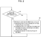
- Fig. 2 is a flowchart illustrating an example of how the fuel cell system of the first embodiment operates (runs).
- the first temperature detector 21 detects the combustion temperature of the combustor 2, and it is determined whether a temperature T1 detected by the first temperature detector 21 is lower than the preset first threshold S1 (step S1).
- a temperature T1 detected by the first temperature detector 21 is lower than the preset first threshold S1 (step S1).
- the first threshold S1 is set at a combustion temperature at which the combustor 2 is expected to produce carbon monoxide to an extent that its concentration in the combustion exhaust gas is at the predetermined value.
- the first threshold S1 is used to compare and determine the temperature T1 detected by the first temperature detector 21.
- the first threshold S1 may be, for example, a combustion temperature of the combustor 2 at which the concentration of carbon monoxide in the combustion exhaust gas is expected to start to increase.
- the first threshold S1 is not limited to this.
- step S1 If in step S1, the temperature T1 detected by the first temperature detector 21 is equal to or higher than the first threshold S1, the fuel cell system 100 continues its operation as it is, and the fuel cell system 100 resumes performing the operation of step S1 whenever deemed necessary.
- step S2 the fuel cell system 100 performs, in step S2, at least one of: the operation of increasing the ratio of the air consumed by the cathode of the SOFC 1 to the air supplied to the cathode thereof; the operation of decreasing the ratio of the hydrogen-containing gas consumed by the anode of the SOFC 1 to the hydrogen-containing gas supplied to the anode thereof; and the operation of decreasing the amount of water supplied to the reformer 4.
- the air supplier 12 may be controlled so as to decrease the flow rate of the air supplied to the cathode of the SOFC 1.
- the material supplier 10 may be controlled so as to increase the flow rate of the material supplied to the reformer 4.
- the fuel cell system 100 may be controlled so as to decrease the amount of power generated by the SOFC 1.
- the water supplier 11 may be controlled so as to decrease the flow rate of water supplied to the reformer 4.
- the fuel cell system 100 and the method of running the fuel cell system 100 of the embodiment are capable of making the combustion state of the combustor 2 more stable than ever. Thereby, the combustion state of the combustor 2 can be improved while the combustor 2 is continuing its combustion. Thus, damage on the electrolyte (ceramic) of the SOFC 1 which is caused by a rapid change in the temperature of the SOFC 1 can be more inhibited than ever. Accordingly, the durability of the fuel cell system 100 can be improved.
- the first threshold S1 is set in advance at a combustion temperature at which the combustor 2 can keep the steady combustion state. Accordingly, if the temperature T1 detected by the first temperature detector 21 is lower than the first threshold S1 although the combustor 2 is forming the flame, at least one of the foregoing operations is performed.
- the combustor 2 combusts the anode-off gas discharged from the anode of the SOFC 1 and the cathode-off gas discharged from the cathode of the SOFC 1, there is likelihood that the amount of cathode-off gas (air) sent to the combustor 2 becomes greater than the amount of anode-off gas sent to the combustor 2. In this case, the combustion state of the combustor 2 is more likely to get into an unstable lean-burn condition.
- the fuel cell system 100 and the method of running the fuel cell system 100 of the embodiment perform the operation of increasing the ratio of the air consumed by the cathode of the SOFC 1 to the air supplied to the cathode of the SOFC 1, and thereby can decrease the amount of cathode-off gas sent to the combustor 2.
- This decrease makes the amount of cathode-off gas smaller than the amount of anode-off gas.
- the system and the method perform the operation of decreasing the ratio of the hydrogen-containing gas consumed by the anode of the SOFC 1 to the hydrogen-containing gas supplied to the anode of the SOFC 1, and thereby can increase the amount of anode-off gas sent to the combustor 2.
- This increase makes the amount of anode-off gas larger than the amount of cathode-off gas.
- the system and the method perform the operation of decreasing the amount of water supplied to the reformer 4, and thereby can decrease the amount of steam in the hydrogen-containing gas (hydrogen gas) sent from the reformer 4 to the anode of the SOFC 1.
- This decrease makes it possible to decrease the quantity of heat which the reformer 4 needs from the combustion exhaust gas to evaporate the water, and thereby increases the amount of heat exchanged between the air in the air heat exchanger 7 and the combustion exhaust gas.
- the fuel cell system 100 and the method of running the fuel cell system 100 of the embodiment perform the operation of: detecting the combustion temperature of the combustor 2 using the first temperature detector 21; and comparing the temperature T1 detected by the first temperature detector 21 with the first threshold S1; and thereby inhibiting the decrease in the combustion temperature of the combustor 2.
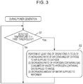
- Fig. 3 is a flowchart illustrating an example of how a fuel cell system of a first example of the first embodiment operates.
- the fuel cell system 100 of this example is the fuel cell system 100 of the first embodiment in which if the temperature T1 detected by the first temperature detector 21 is lower than the first threshold S1 although the SOFC 1 is generating power, the controller 20 performs at least one of: the operation of increasing the ratio of the air consumed by the cathode of the SOFC 1 to the air supplied to the cathode thereof; the operation of decreasing the ratio of the hydrogen-containing gas consumed by the anode of the SOFC 1 to the hydrogen-containing gas supplied to the anode thereof; and the operation of decreasing the amount of water supplied to the reformer 4.
- the specific examples of what are controlled by the controller 20 for the operation in step S2 in Fig. 3 are the same as those of the first embodiment, and descriptions for them will be omitted.
- steps S1 and S2 in Fig. 3 are the same as those in Fig. 2 , and detailed descriptions for the steps will be omitted.
- the fuel cell system 100 of this example detects the combustion temperature of the combustor 2 using the first temperature detector 21, compares the temperature T1 detected by the first temperature detector 21 with the first threshold S1, and makes the determination. If the temperature T1 detected by the first temperature detector 21 is lower than the first threshold S1, the fuel cell system 100 performs, in step S2, the operation of inhibiting the decrease in the combustion temperature of the combustor 2.
- the combustion state of the combustor 2 becomes stable while the SOFC 1 is generating power.
- the fuel cell system 100 can be run for the power generation with the durability of the SOFC 1 taken into consideration.
- the combustor 2 loses the flame, no hydrogen-containing gas can be supplied to the anode of the SOFC 1, and no air to be sent to the cathode of the SOFC 1 can be heated. In this case, the SOFC 1 can no longer continue the power generation.
- the fuel cell stack in the SOFC 1 cools rapidly and becomes highly likely to suffer from thermal distortion, since the fuel cell stack in the SOFC 1 has been in a high-temperature state while the fuel cell system 100 is generating power.
- the electrolyte (ceramic) of the SOFC 1 is vulnerable to thermal distortion. Repeated loss of the flame in the combustor 2 would pose a risk that: the electrolyte is damaged; and the fuel cell system 100 becomes no longer able to continue the normal power generating operation.
- the fuel cell system 100 of this example can reduce such a risk since the fuel cell system 100 is capable of stabilizing the combustion state of the combustor 2 by performing at least one of the foregoing operations.
- the amount of carbon monoxide gas increases in the combustion exhaust gas while the combustor 2 is in the process of losing the flame.
- the fuel cell system 100 of this example can reduce such a risk by performing at least one of the foregoing operations.
- the fuel cell system 100 and the method of running the fuel cell system 100 of this example may be the same as the fuel cell system 100 and the method of running the fuel cell system 100 of the first embodiment, except for the above-discussed feature.
- Fig. 4 is a flowchart illustrating an example of how a fuel cell system of a second example of the first embodiment operates.
- the fuel cell system 100 of this example is the fuel cell system 100 of the first embodiment or the first example of the first embodiment in which if a hydrogen consumption ratio of the hydrogen-containing gas consumed by the anode of the SOFC 1 to the hydrogen-containing gas supplied to the anode thereof is higher than a preset hydrogen consumption ratio, the controller 20 performs at least one of: the operation of increasing the ratio of the air consumed by the cathode of the SOFC 1 to the air supplied to the cathode thereof; the operation of decreasing the ratio of the hydrogen-containing gas consumed by the anode of the SOFC 1 to the hydrogen-containing gas supplied to the anode thereof; and the operation of decreasing the amount of water supplied to the reformer 4.
- step S2 in Fig. 4 the specific examples of what are controlled by the controller 20 for the operation in step S2 in Fig. 4 are the same as those of the first embodiment, and descriptions for them will be omitted.
- steps S1 and S2 in Fig. 4 are the same as those in Fig. 2 , and detailed descriptions for the steps will be omitted.
- the fuel cell system 100 would be able to be run with high efficiency by increasing the amount of hydrogen gas used by the anode of the SOFC 1.
- a fuel utilization ratio U f of the SOFC 1 (a ratio of an amount of hydrogen gas used for the power generation by the SOFC 1 to an amount of hydrogen gas supplied to the SOFC 1 which is expressed by 1) would exceed the preset hydrogen consumption ratio, the fuel cell system 100 would be able to be temporarily run with high efficiency.
- a higher fuel utilization ratio U f of the SOFC 1 means an inevitable decrease in the amount of anode-off gas sent to the combustor 2.
- the combustor 2 would be more likely to get into lean burn in which the amount of cathode-off gas is larger than the amount of anode-off gas.
- an increase in the air ratio in the combustion of the combustor 2 would get the flame formed by the combustor 2 closer to the flameout area in which the flame cannot be normally maintained by the combustor 2.
- step S3 the fuel cell system 100 of this example proceeds to step S1, where the fuel cell system 100 detects the combustion temperature of the combustor 2 using the first temperature detector 21, compares the temperature T1 detected by the first temperature detector 21 with the first threshold S1, and makes the determination. If the temperature T1 detected by the first temperature detector 21 is lower than the first threshold S1, the fuel cell system 100 performs, in step S2, the operation of inhibiting the decrease in the combustion temperature of the combustor 2.
- the fuel cell system 100 is capable of stabilizing the combustion state of the combustor 2 by performing at least one of the foregoing operations. Thereby, the fuel cell system 100 can reduce a risk that the decrease in the combustion temperature of the combustor 2 worsens the combustion state of the combustor 2 and makes it difficult for the combustor 2 to maintain the combustion reaction appropriately.
- the fuel cell system 100 and the method of running the fuel cell system 100 of this example may be the same as the fuel cell system 100 and the method of running the fuel cell system 100 of the first embodiment or the first example of the first embodiment, except for the above-discussed feature.
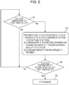
- Fig. 5 is a flowchart illustrating an example of how a fuel cell system of a first modification of the first embodiment operates.
- the fuel cell system 100 of this modification is the fuel cell system 100 of any one of the first embodiment as well as the first and second examples of the first embodiment in which: if the temperature T1 detected by the first temperature detector 21 is lower than the first threshold S1, the controller 20 performs at least one of the operation of increasing the ratio of the air consumed by the cathode of the SOFC 1 to the air supplied to the cathode thereof, the operation of decreasing the ratio of the hydrogen-containing gas consumed by the anode of the SOFC 1 to the hydrogen-containing gas supplied to the anode thereof, and the operation of decreasing the amount of water supplied to the reformer 4; and thereafter, if the temperature T1 detected by the first temperature detector 21 is lower than a second threshold S2 set in advance at a temperature lower than the first threshold S1, the controller 20 stops the run of the fuel cell system 100.
- step S2 in Fig. 5 the specific examples of what are controlled by the controller 20 for the operation in step S2 in Fig. 5 are the same as those of the first embodiment. For this reason, descriptions for them will be omitted.
- steps S1 and S2 in Fig. 5 are the same as those in Fig. 2 , and detailed descriptions for the steps will be omitted.
- the fuel cell system 100 of this modification performs the operation of inhibiting the decrease in the combustion temperature of the combustor 2 in step S2. Thereafter, while the combustor 2 is forming the flame, the fuel cell system 100 detects the combustion temperature of the combustor 2 using the first temperature detector 21, and determines whether the temperature T1 detected by the first temperature detector 21 is lower than the preset second threshold S2 (step S4).
- the combustion state of the combustor 2 for example, the concentration of carbon monoxide in the combustion exhaust gas
- the temperature T1 detected by the first temperature detector 21 it is possible to estimate the combustion temperature at which the combustor 2 is kept in the steady combustion state (for example, the state in which the concentration of carbon monoxide in the combustion exhaust gas is not equal to or higher than the predetermined value).
- the second threshold S2 is set at a temperature lower than the first threshold S1 and equal to a combustion temperature at which the combustor 2 is expected to produce carbon monoxide to an extent that its concentration in the combustion exhaust gas quickly increases to a predetermined value because of a worse combustion state of the combustor 2 than in step S1.
- the second threshold S2 is used to compare and determine the temperature T1 detected by the first temperature detector 21.
- the second threshold S2 may be, for example, a combustion temperature of the combustor 2 at which the concentration of carbon monoxide in the combustion exhaust gas is expected to be so high as to require the combustor 2 to be stopped.
- the second threshold S2 is not limited to this.
- the fuel cell system 100 continues its operation as it is, and resumes performing the operation of step S1 whenever deemed necessary.
- the fuel cell system 100 stops its operation (step S5).
- the fuel cell system 100 is capable of adequately performing the stop operation if the temperature T1 detected by the first temperature detector 21 is lower than the second threshold S2.
- the fuel cell system 100 of this modification can reduce such a risk since the fuel cell system 100 is capable of appropriately performing the stop operation in accordance with the predetermined sequence.
- the fuel cell system 100 can reduce such a risk since the fuel cell system 100 is capable of appropriately performing the stop operation in accordance with the predetermined sequence.
- the fuel cell system 100 and the method of running the fuel cell system 100 of this modification may be the same as the fuel cell system 100 and the method of running the fuel cell system 100 in any one of the first embodiment as well as the first and second examples of the first embodiment, except for the above-discussed feature.
- the operation of the fuel cell system 100 of this modification may be performed if the hydrogen consumption ratio of the hydrogen-containing gas consumed by the anode of the SOFC 1 to the hydrogen-containing gas supplied to the anode thereof is higher than the preset hydrogen consumption ratio.
- Fig. 6 is a flowchart illustrating an example of how a fuel cell system of a second modification of the first embodiment operates.
- the fuel cell system 100 of this modification is the fuel cell system 100 of any one of the first embodiment as well as the first and second examples of the first embodiment in which: if the temperature T1 detected by the first temperature detector 21 is lower than the first threshold S1, the controller 20 performs at least one of the operation of increasing the ratio of the air consumed by the cathode of the SOFC 1 to the air supplied to the cathode thereof, the operation of decreasing the ratio of the hydrogen-containing gas consumed by the anode of the SOFC 1 to the hydrogen-containing gas supplied to the anode thereof, and the operation of decreasing the amount of water supplied to the reformer 4; and thereafter, if the temperature T1 detected by the first temperature detector 21 is a temperature lower than the first threshold S1, and is lower than a third threshold S3 which is set in advance at a temperature beyond which the combustor 2 loses the flame, the controller 20 stops the run of the fuel cell system 100.
- step S2 in Fig. 6 the specific examples of what are controlled by the controller 20 for the operation in step S2 in Fig. 6 are the same as those of the first embodiment. For this reason, descriptions for them will be omitted.
- steps S1 and S2 in Fig. 6 are the same as those in Fig. 2 , and detailed descriptions for the steps will be omitted.
- the fuel cell system 100 of this modification performs the operation of inhibiting the decrease in the combustion temperature of the combustor 2 in step S2. Thereafter, while the combustor 2 is forming the flame, the fuel cell system 100 detects the combustion temperature of the combustor 2 using the first temperature detector 21, and determines whether the temperature T1 detected by the first temperature detector 21 is lower than the preset third threshold S3 (step S6).
- the third threshold S3 is set at the temperature which is lower than the first threshold S1, and beyond which the combustor 2 loses the flame because of a worse combustion state of the combustor 2 than in step S1.
- the third threshold S3 is used to compare and determine the temperature T1 detected by the first temperature detector 21.
- the fuel cell system 100 continues its operation as it is, and resumes performing the operation of step S1 whenever deemed necessary.
- the fuel cell system 100 stops its operation (step S5).
- the fuel cell system 100 is capable of adequately performing the stop operation if the temperature T1 detected by the first temperature detector 21 is lower than the third threshold S3.
- the combustor 2 loses the flame immediately thereafter. If the combustor 2 would lose the flame suddenly, the temperature of the fuel cell stack in the SOFC 1 would be likely to change rapidly.
- the fuel cell system 100 of this modification can reduce such a risk since the fuel cell system 100 is capable of stopping appropriately in accordance with the predetermined sequence.
- the temperature T1 detected by the first temperature detector 21 is lower than the third threshold S3, some trouble may have occurred in the material supplier 10, the water supplier 11, the air supplier 12 or the like. If the fuel cell system 100 would continue its operation as it is, the fuel cell system 100 would be likely to break down.
- the fuel cell system 100 of this modification can reduce such a risk since the fuel cell system 100 is capable of appropriately performing the stop operation in accordance with the predetermined sequence.
- the fuel cell system 100 and the method of running the fuel cell system 100 of this modification may be the same as the fuel cell system 100 and the method of running the fuel cell system 100 in any one of the first embodiment as well as the first and second examples of the first embodiment, except for the above-discussed feature.
- the operation of the fuel cell system 100 of this modification may be performed if the hydrogen consumption ratio of the hydrogen-containing gas consumed by the anode of the SOFC 1 to the hydrogen-containing gas supplied to the anode thereof is higher than the preset hydrogen consumption ratio.
- the inventors have eagerly examined problems involved in the operation of increasing the ratio of the air consumed by the cathode of the SOFC 1 to the air supplied to the cathode thereof, and obtains the following findings.
- the solid oxide fuel cell system 100 is configured to inhibit a rise in temperature of the SOFC 1 by collecting heat which is produced while the SOFC 1 is generating power, by use of air to be used for the power generation. For this reason, the decrease in the flow rate of the air supplied to the cathode of the SOFC 1 results in a rise in the operating temperature of the SOFC 1. If the operating temperature of the SOFC 1 rises excessively, even the solid oxide fuel cell system 100 becomes more likely to lower the power generation performance during a long-term operation since the excessive temperature rise thermally degrades the electrolyte of the SOFC 1, peripheral members and the like.
- the fuel cell system 100 of the second embodiment is the fuel cell system of any one of the first embodiment, the first and second examples of the first embodiments, as well as the first and second modifications of the first embodiment, in which: the fuel cell system 100 includes a second temperature detector 22 which detects a temperature of the SOFC 1; and if the temperature T1 detected by the first temperature detector 21 is lower than the first threshold S1, the controller 20 performs the operation of increasing the ratio of the air consumed by the cathode of the SOFC 1 to the air supplied to the cathode thereof such that the temperature T2 detected by the second temperature detector 22 does not exceed a preset fourth threshold S4.
- Fig. 7 is a diagram illustrating an example of the fuel cell system of the second embodiment.
- the fuel cell system 100 includes the SOFC 1, the combustor 2, the reformer 4, the air heat exchanger 7, the material supplier 10, the water supplier 11, the air supplier 12, the hydrogen-containing gas supply route 13, the air supply route 14, the anode-off gas discharge route 15, the cathode-off gas discharge route 16, the flame guide 18, the controller 20, the first temperature detector 21, and the second temperature detector 22.
- the SOFC 1, the combustor 2, the reformer 4, the air heat exchanger 7, the material supplier 10, the water supplier 11, the air supplier 12, the hydrogen-containing gas supply route 13, the air supply route 14, the anode-off gas discharge route 15, the cathode-off gas discharge route 16, the flame guide 18, and the first temperature detector 21 are the same as those of the first embodiment. For this reason, descriptions for them will be omitted.
- the second temperature detector 22 detects the temperature of the SOFC 1.
- the second temperature detector 22 may have any configuration as long as it is capable of detecting the temperature of the SOFC 1.
- the second temperature detector 22 may be provided, for example, inside the SOFC 1 to detect the temperature of the SOFC 1 directly. Otherwise, the second temperature detector 22 may be provided in a predetermined place which correlates with the temperature of the SOFC 1 to detect the temperature of the SOFC 1 indirectly. Examples of the second temperature detector 22 include a thermocouple, and a thermistor.
- the controller 20 controls the air supplier 12 in order to decrease the flow rate of the air supplied to the cathode of the SOFC 1 within a range in which the temperature T2 detected by the second temperature detector 22 does not exceed the preset fourth threshold S4.
- Fig. 8 is a flowchart illustrating an example of how the fuel cell system of the second embodiment operates. Incidentally, steps S1 and S2 in Fig. 8 are the same as those in Fig. 2 . For this reason, detailed descriptions for the steps will be omitted.
- step S1 the fuel cell system 100 of the embodiment performs, in step S2, at least one of: the operation of increasing the ratio of the air consumed by the cathode of the SOFC 1 to the air supplied to the cathode thereof; the operation of decreasing the ratio of the hydrogen-containing gas consumed by the anode of the SOFC 1 to the hydrogen-containing gas supplied to the anode thereof; and the operation of decreasing the amount of water supplied to the reformer 4.
- the temperature of the SOFC 1 is detected by the second temperature detector 22, and it is determined whether the temperature T2 detected by the second temperature detector 22 is higher than the preset fourth threshold S4 (step S7).
- the fourth threshold S4 for step S7 may be set at an upper limit value of a temperature at which the power generation performance of the fuel cell system 100 is less likely to decrease during a long-term operation.
- step S7 the temperature T2 detected by the second temperature detector 22 is equal to or lower than the fourth threshold S4, the fuel cell system 100 continues its operation as it is, and resumes performing the operation of step S1 whenever deemed necessary.
- step S7 the temperature T2 detected by the second temperature detector 22 is higher than the preset fourth threshold S4
- the operation of increasing the ratio of the air consumed by the cathode of the SOFC 1 to the air supplied to the cathode thereof is performed in step S8 such that the temperature T2 detected by the second temperature detector 22 does not exceed the fourth threshold S4.
- the air supplier 12 may be controlled so as to decrease the flow rate of the air supplied to the cathode of the SOFC 1 within the range in which the temperature T2 detected by the second temperature detector 22 does not exceed the fourth threshold S4.
- the operation of the fuel cell system 100 may be stopped if the temperature T2 detected by the second temperature detector 22 is higher than the fourth threshold S4.
- the fuel cell system 100 of the embodiment is capable of: performing the operation of inhibiting the decrease in the combustion temperature of the combustor 2; and decreasing the flow rate of the air supplied to the cathode of the SOFC 1.
- the fuel cell system 100 is capable of: inhibiting the thermal degradation of the electrolyte of the SOFC 1, peripheral members and the like; and making the combustion state of the combustor 2 more stable than ever while the combustor 2 is forming the flame.
- the fuel cell system 100 and the method of running the fuel cell system 100 of this embodiment may be the same as the fuel cell system 100 and the method of running the fuel cell system 100 in any one of the first embodiment, the first and second examples of the first embodiment, as well as the first and second modifications of the first embodiment, except for the above-discussed feature.
- the operation of the fuel cell system 100 of this embodiment may be performed if the hydrogen consumption ratio of the hydrogen-containing gas consumed by the anode of the SOFC 1 to the hydrogen-containing gas supplied to the anode thereof is higher than the preset hydrogen consumption ratio.
- first embodiment the first and second examples of the first embodiment, the first and second modifications of the first embodiment, and the second embodiment may be combined together unless they exclude each other.
- the aspect of the present disclosure is applicable to fuel cell systems and methods for running fuel cell systems which are thereby capable of making the combustion state of the combust more stable than ever while the combustor is forming the flame.
Landscapes
- Engineering & Computer Science (AREA)
- Chemical & Material Sciences (AREA)
- Life Sciences & Earth Sciences (AREA)
- Manufacturing & Machinery (AREA)
- Sustainable Development (AREA)
- Sustainable Energy (AREA)
- Chemical Kinetics & Catalysis (AREA)
- Electrochemistry (AREA)
- General Chemical & Material Sciences (AREA)
- Combustion & Propulsion (AREA)
- Fuel Cell (AREA)
- Hydrogen, Water And Hydrids (AREA)
Applications Claiming Priority (1)
| Application Number | Priority Date | Filing Date | Title |
|---|---|---|---|
| JP2016202582 | 2016-10-14 |
Publications (2)
| Publication Number | Publication Date |
|---|---|
| EP3309887A1 EP3309887A1 (en) | 2018-04-18 |
| EP3309887B1 true EP3309887B1 (en) | 2020-04-01 |
Family
ID=60080684
Family Applications (1)
| Application Number | Title | Priority Date | Filing Date |
|---|---|---|---|
| EP17195882.0A Active EP3309887B1 (en) | 2016-10-14 | 2017-10-11 | Fuel cell system and method of running fuel cell system |
Country Status (3)
| Country | Link |
|---|---|
| US (1) | US10833339B2 (enExample) |
| EP (1) | EP3309887B1 (enExample) |
| JP (1) | JP6960610B2 (enExample) |
Families Citing this family (3)
| Publication number | Priority date | Publication date | Assignee | Title |
|---|---|---|---|---|
| CN113079706B (zh) | 2018-11-20 | 2024-05-28 | 蓝界科技控股公司 | 燃料电池系统及其用途和操作方法 |
| EP3933990B1 (en) * | 2019-02-28 | 2024-10-09 | Kyocera Corporation | Fuel cell apparatus |
| CN112820897B (zh) * | 2021-02-04 | 2024-08-23 | 安德森热能科技(苏州)有限责任公司 | 一种用于sofc系统的高调节比燃烧集成装置 |
Family Cites Families (4)
| Publication number | Priority date | Publication date | Assignee | Title |
|---|---|---|---|---|
| JP5495167B2 (ja) | 2008-09-12 | 2014-05-21 | Toto株式会社 | 燃料電池モジュール |
| EP2660911A1 (en) * | 2010-12-28 | 2013-11-06 | JX Nippon Oil & Energy Corporation | Fuel cell system |
| JP6264121B2 (ja) * | 2014-03-20 | 2018-01-24 | アイシン精機株式会社 | 燃料電池システム |
| US10050293B2 (en) | 2014-11-28 | 2018-08-14 | Panasonic Intellectual Property Management Co., Ltd. | Method for operating fuel cell system and method for estimating composition of fuel used in fuel cell system |
-
2017
- 2017-09-22 US US15/713,124 patent/US10833339B2/en active Active
- 2017-09-26 JP JP2017184437A patent/JP6960610B2/ja active Active
- 2017-10-11 EP EP17195882.0A patent/EP3309887B1/en active Active
Non-Patent Citations (1)
| Title |
|---|
| None * |
Also Published As
| Publication number | Publication date |
|---|---|
| US20180108922A1 (en) | 2018-04-19 |
| JP2018067534A (ja) | 2018-04-26 |
| US10833339B2 (en) | 2020-11-10 |
| EP3309887A1 (en) | 2018-04-18 |
| JP6960610B2 (ja) | 2021-11-05 |
Similar Documents
| Publication | Publication Date | Title |
|---|---|---|
| JP5164441B2 (ja) | 燃料電池システムの起動方法 | |
| KR101361597B1 (ko) | 개질기 시스템, 연료 전지 시스템, 및 그 운전 방법 | |
| US8048577B2 (en) | Hydrogen generator with a combustor with a control unit | |
| EP2416428B1 (en) | Fuel cell system | |
| JP5214230B2 (ja) | 燃料電池システムの起動方法 | |
| US9431668B2 (en) | Power generation system and operation method thereof | |
| JP2009176660A (ja) | 間接内部改質型固体酸化物形燃料電池の停止方法 | |
| JPWO2017026037A1 (ja) | 固体酸化物形燃料電池システム | |
| JP2009295380A (ja) | 間接内部改質型固体酸化物形燃料電池の停止方法 | |
| JP6635851B2 (ja) | 燃料電池モジュールおよび燃料電池モジュールの制御方法 | |
| JP5325666B2 (ja) | 間接内部改質型固体酸化物形燃料電池の停止方法 | |
| EP3309887B1 (en) | Fuel cell system and method of running fuel cell system | |
| KR20140009905A (ko) | 발전 시스템 및 그 운전 방법 | |
| JP2010044909A (ja) | 間接内部改質型固体酸化物形燃料電池の停止方法 | |
| JP7162170B2 (ja) | 固体酸化物形燃料電池システム | |
| WO2022118682A1 (ja) | 燃料電池モジュール | |
| JP2008217999A (ja) | 高温型燃料電池システムの運転方法 | |
| JP2016207308A (ja) | 固体酸化物形燃料電池システムおよびその起動方法 | |
| JP5122028B2 (ja) | 発電システム及びその運転方法 | |
| JP5307592B2 (ja) | 間接内部改質型固体酸化物形燃料電池システムの運転方法 | |
| JP6444197B2 (ja) | 燃料電池モジュール | |
| JP2007331951A (ja) | 水素生成装置および燃料電池システム | |
| JP7367736B2 (ja) | 燃料電池モジュール | |
| JP2010257823A (ja) | 燃料電池システムの燃焼装置 | |
| JP2010225284A (ja) | 間接内部改質型固体酸化物形燃料電池システムの運転方法 |
Legal Events
| Date | Code | Title | Description |
|---|---|---|---|
| PUAI | Public reference made under article 153(3) epc to a published international application that has entered the european phase |
Free format text: ORIGINAL CODE: 0009012 |
|
| STAA | Information on the status of an ep patent application or granted ep patent |
Free format text: STATUS: THE APPLICATION HAS BEEN PUBLISHED |
|
| AK | Designated contracting states |
Kind code of ref document: A1 Designated state(s): AL AT BE BG CH CY CZ DE DK EE ES FI FR GB GR HR HU IE IS IT LI LT LU LV MC MK MT NL NO PL PT RO RS SE SI SK SM TR |
|
| AX | Request for extension of the european patent |
Extension state: BA ME |
|
| STAA | Information on the status of an ep patent application or granted ep patent |
Free format text: STATUS: REQUEST FOR EXAMINATION WAS MADE |
|
| 17P | Request for examination filed |
Effective date: 20181017 |
|
| RBV | Designated contracting states (corrected) |
Designated state(s): AL AT BE BG CH CY CZ DE DK EE ES FI FR GB GR HR HU IE IS IT LI LT LU LV MC MK MT NL NO PL PT RO RS SE SI SK SM TR |
|
| STAA | Information on the status of an ep patent application or granted ep patent |
Free format text: STATUS: EXAMINATION IS IN PROGRESS |
|
| 17Q | First examination report despatched |
Effective date: 20190116 |
|
| GRAP | Despatch of communication of intention to grant a patent |
Free format text: ORIGINAL CODE: EPIDOSNIGR1 |
|
| STAA | Information on the status of an ep patent application or granted ep patent |
Free format text: STATUS: GRANT OF PATENT IS INTENDED |
|
| INTG | Intention to grant announced |
Effective date: 20191025 |
|
| GRAS | Grant fee paid |
Free format text: ORIGINAL CODE: EPIDOSNIGR3 |
|
| GRAA | (expected) grant |
Free format text: ORIGINAL CODE: 0009210 |
|
| STAA | Information on the status of an ep patent application or granted ep patent |
Free format text: STATUS: THE PATENT HAS BEEN GRANTED |
|
| AK | Designated contracting states |
Kind code of ref document: B1 Designated state(s): AL AT BE BG CH CY CZ DE DK EE ES FI FR GB GR HR HU IE IS IT LI LT LU LV MC MK MT NL NO PL PT RO RS SE SI SK SM TR |
|
| REG | Reference to a national code |
Ref country code: GB Ref legal event code: FG4D |
|
| REG | Reference to a national code |
Ref country code: CH Ref legal event code: EP Ref country code: AT Ref legal event code: REF Ref document number: 1252547 Country of ref document: AT Kind code of ref document: T Effective date: 20200415 |
|
| REG | Reference to a national code |
Ref country code: DE Ref legal event code: R096 Ref document number: 602017013903 Country of ref document: DE |
|
| REG | Reference to a national code |
Ref country code: IE Ref legal event code: FG4D |
|
| PG25 | Lapsed in a contracting state [announced via postgrant information from national office to epo] |
Ref country code: BG Free format text: LAPSE BECAUSE OF FAILURE TO SUBMIT A TRANSLATION OF THE DESCRIPTION OR TO PAY THE FEE WITHIN THE PRESCRIBED TIME-LIMIT Effective date: 20200701 |
|
| REG | Reference to a national code |
Ref country code: NL Ref legal event code: MP Effective date: 20200401 |
|
| REG | Reference to a national code |
Ref country code: LT Ref legal event code: MG4D |
|
| PG25 | Lapsed in a contracting state [announced via postgrant information from national office to epo] |
Ref country code: SE Free format text: LAPSE BECAUSE OF FAILURE TO SUBMIT A TRANSLATION OF THE DESCRIPTION OR TO PAY THE FEE WITHIN THE PRESCRIBED TIME-LIMIT Effective date: 20200401 Ref country code: GR Free format text: LAPSE BECAUSE OF FAILURE TO SUBMIT A TRANSLATION OF THE DESCRIPTION OR TO PAY THE FEE WITHIN THE PRESCRIBED TIME-LIMIT Effective date: 20200702 Ref country code: NO Free format text: LAPSE BECAUSE OF FAILURE TO SUBMIT A TRANSLATION OF THE DESCRIPTION OR TO PAY THE FEE WITHIN THE PRESCRIBED TIME-LIMIT Effective date: 20200701 Ref country code: FI Free format text: LAPSE BECAUSE OF FAILURE TO SUBMIT A TRANSLATION OF THE DESCRIPTION OR TO PAY THE FEE WITHIN THE PRESCRIBED TIME-LIMIT Effective date: 20200401 Ref country code: PT Free format text: LAPSE BECAUSE OF FAILURE TO SUBMIT A TRANSLATION OF THE DESCRIPTION OR TO PAY THE FEE WITHIN THE PRESCRIBED TIME-LIMIT Effective date: 20200817 Ref country code: IS Free format text: LAPSE BECAUSE OF FAILURE TO SUBMIT A TRANSLATION OF THE DESCRIPTION OR TO PAY THE FEE WITHIN THE PRESCRIBED TIME-LIMIT Effective date: 20200801 Ref country code: CZ Free format text: LAPSE BECAUSE OF FAILURE TO SUBMIT A TRANSLATION OF THE DESCRIPTION OR TO PAY THE FEE WITHIN THE PRESCRIBED TIME-LIMIT Effective date: 20200401 Ref country code: NL Free format text: LAPSE BECAUSE OF FAILURE TO SUBMIT A TRANSLATION OF THE DESCRIPTION OR TO PAY THE FEE WITHIN THE PRESCRIBED TIME-LIMIT Effective date: 20200401 Ref country code: LT Free format text: LAPSE BECAUSE OF FAILURE TO SUBMIT A TRANSLATION OF THE DESCRIPTION OR TO PAY THE FEE WITHIN THE PRESCRIBED TIME-LIMIT Effective date: 20200401 |
|
| REG | Reference to a national code |
Ref country code: AT Ref legal event code: MK05 Ref document number: 1252547 Country of ref document: AT Kind code of ref document: T Effective date: 20200401 |
|
| PG25 | Lapsed in a contracting state [announced via postgrant information from national office to epo] |
Ref country code: RS Free format text: LAPSE BECAUSE OF FAILURE TO SUBMIT A TRANSLATION OF THE DESCRIPTION OR TO PAY THE FEE WITHIN THE PRESCRIBED TIME-LIMIT Effective date: 20200401 Ref country code: LV Free format text: LAPSE BECAUSE OF FAILURE TO SUBMIT A TRANSLATION OF THE DESCRIPTION OR TO PAY THE FEE WITHIN THE PRESCRIBED TIME-LIMIT Effective date: 20200401 Ref country code: HR Free format text: LAPSE BECAUSE OF FAILURE TO SUBMIT A TRANSLATION OF THE DESCRIPTION OR TO PAY THE FEE WITHIN THE PRESCRIBED TIME-LIMIT Effective date: 20200401 |
|
| PG25 | Lapsed in a contracting state [announced via postgrant information from national office to epo] |
Ref country code: AL Free format text: LAPSE BECAUSE OF FAILURE TO SUBMIT A TRANSLATION OF THE DESCRIPTION OR TO PAY THE FEE WITHIN THE PRESCRIBED TIME-LIMIT Effective date: 20200401 |
|
| REG | Reference to a national code |
Ref country code: DE Ref legal event code: R097 Ref document number: 602017013903 Country of ref document: DE |
|
| PG25 | Lapsed in a contracting state [announced via postgrant information from national office to epo] |
Ref country code: RO Free format text: LAPSE BECAUSE OF FAILURE TO SUBMIT A TRANSLATION OF THE DESCRIPTION OR TO PAY THE FEE WITHIN THE PRESCRIBED TIME-LIMIT Effective date: 20200401 Ref country code: DK Free format text: LAPSE BECAUSE OF FAILURE TO SUBMIT A TRANSLATION OF THE DESCRIPTION OR TO PAY THE FEE WITHIN THE PRESCRIBED TIME-LIMIT Effective date: 20200401 Ref country code: EE Free format text: LAPSE BECAUSE OF FAILURE TO SUBMIT A TRANSLATION OF THE DESCRIPTION OR TO PAY THE FEE WITHIN THE PRESCRIBED TIME-LIMIT Effective date: 20200401 Ref country code: AT Free format text: LAPSE BECAUSE OF FAILURE TO SUBMIT A TRANSLATION OF THE DESCRIPTION OR TO PAY THE FEE WITHIN THE PRESCRIBED TIME-LIMIT Effective date: 20200401 Ref country code: SM Free format text: LAPSE BECAUSE OF FAILURE TO SUBMIT A TRANSLATION OF THE DESCRIPTION OR TO PAY THE FEE WITHIN THE PRESCRIBED TIME-LIMIT Effective date: 20200401 Ref country code: IT Free format text: LAPSE BECAUSE OF FAILURE TO SUBMIT A TRANSLATION OF THE DESCRIPTION OR TO PAY THE FEE WITHIN THE PRESCRIBED TIME-LIMIT Effective date: 20200401 Ref country code: ES Free format text: LAPSE BECAUSE OF FAILURE TO SUBMIT A TRANSLATION OF THE DESCRIPTION OR TO PAY THE FEE WITHIN THE PRESCRIBED TIME-LIMIT Effective date: 20200401 |
|
| PLBE | No opposition filed within time limit |
Free format text: ORIGINAL CODE: 0009261 |
|
| STAA | Information on the status of an ep patent application or granted ep patent |
Free format text: STATUS: NO OPPOSITION FILED WITHIN TIME LIMIT |
|
| PG25 | Lapsed in a contracting state [announced via postgrant information from national office to epo] |
Ref country code: PL Free format text: LAPSE BECAUSE OF FAILURE TO SUBMIT A TRANSLATION OF THE DESCRIPTION OR TO PAY THE FEE WITHIN THE PRESCRIBED TIME-LIMIT Effective date: 20200401 Ref country code: SK Free format text: LAPSE BECAUSE OF FAILURE TO SUBMIT A TRANSLATION OF THE DESCRIPTION OR TO PAY THE FEE WITHIN THE PRESCRIBED TIME-LIMIT Effective date: 20200401 |
|
| 26N | No opposition filed |
Effective date: 20210112 |
|
| PG25 | Lapsed in a contracting state [announced via postgrant information from national office to epo] |
Ref country code: SI Free format text: LAPSE BECAUSE OF FAILURE TO SUBMIT A TRANSLATION OF THE DESCRIPTION OR TO PAY THE FEE WITHIN THE PRESCRIBED TIME-LIMIT Effective date: 20200401 |
|
| REG | Reference to a national code |
Ref country code: CH Ref legal event code: PL |
|
| PG25 | Lapsed in a contracting state [announced via postgrant information from national office to epo] |
Ref country code: LU Free format text: LAPSE BECAUSE OF NON-PAYMENT OF DUE FEES Effective date: 20201011 Ref country code: MC Free format text: LAPSE BECAUSE OF FAILURE TO SUBMIT A TRANSLATION OF THE DESCRIPTION OR TO PAY THE FEE WITHIN THE PRESCRIBED TIME-LIMIT Effective date: 20200401 |
|
| REG | Reference to a national code |
Ref country code: BE Ref legal event code: MM Effective date: 20201031 |
|
| PG25 | Lapsed in a contracting state [announced via postgrant information from national office to epo] |
Ref country code: FR Free format text: LAPSE BECAUSE OF NON-PAYMENT OF DUE FEES Effective date: 20201031 |
|
| PG25 | Lapsed in a contracting state [announced via postgrant information from national office to epo] |
Ref country code: BE Free format text: LAPSE BECAUSE OF NON-PAYMENT OF DUE FEES Effective date: 20201031 Ref country code: CH Free format text: LAPSE BECAUSE OF NON-PAYMENT OF DUE FEES Effective date: 20201031 Ref country code: LI Free format text: LAPSE BECAUSE OF NON-PAYMENT OF DUE FEES Effective date: 20201031 |
|
| PG25 | Lapsed in a contracting state [announced via postgrant information from national office to epo] |
Ref country code: IE Free format text: LAPSE BECAUSE OF NON-PAYMENT OF DUE FEES Effective date: 20201011 |
|
| PG25 | Lapsed in a contracting state [announced via postgrant information from national office to epo] |
Ref country code: TR Free format text: LAPSE BECAUSE OF FAILURE TO SUBMIT A TRANSLATION OF THE DESCRIPTION OR TO PAY THE FEE WITHIN THE PRESCRIBED TIME-LIMIT Effective date: 20200401 Ref country code: MT Free format text: LAPSE BECAUSE OF FAILURE TO SUBMIT A TRANSLATION OF THE DESCRIPTION OR TO PAY THE FEE WITHIN THE PRESCRIBED TIME-LIMIT Effective date: 20200401 Ref country code: CY Free format text: LAPSE BECAUSE OF FAILURE TO SUBMIT A TRANSLATION OF THE DESCRIPTION OR TO PAY THE FEE WITHIN THE PRESCRIBED TIME-LIMIT Effective date: 20200401 |
|
| GBPC | Gb: european patent ceased through non-payment of renewal fee |
Effective date: 20211011 |
|
| PG25 | Lapsed in a contracting state [announced via postgrant information from national office to epo] |
Ref country code: MK Free format text: LAPSE BECAUSE OF FAILURE TO SUBMIT A TRANSLATION OF THE DESCRIPTION OR TO PAY THE FEE WITHIN THE PRESCRIBED TIME-LIMIT Effective date: 20200401 |
|
| PG25 | Lapsed in a contracting state [announced via postgrant information from national office to epo] |
Ref country code: GB Free format text: LAPSE BECAUSE OF NON-PAYMENT OF DUE FEES Effective date: 20211011 |
|
| PGFP | Annual fee paid to national office [announced via postgrant information from national office to epo] |
Ref country code: DE Payment date: 20241021 Year of fee payment: 8 |