EP3308450B1 - Elektrischen antriebsmotor - Google Patents
Elektrischen antriebsmotor Download PDFInfo
- Publication number
- EP3308450B1 EP3308450B1 EP16727718.5A EP16727718A EP3308450B1 EP 3308450 B1 EP3308450 B1 EP 3308450B1 EP 16727718 A EP16727718 A EP 16727718A EP 3308450 B1 EP3308450 B1 EP 3308450B1
- Authority
- EP
- European Patent Office
- Prior art keywords
- flux barriers
- drive motor
- electric drive
- pole
- rotor
- Prior art date
- Legal status (The legal status is an assumption and is not a legal conclusion. Google has not performed a legal analysis and makes no representation as to the accuracy of the status listed.)
- Active
Links
Images


Classifications
-
- H—ELECTRICITY
- H02—GENERATION; CONVERSION OR DISTRIBUTION OF ELECTRIC POWER
- H02K—DYNAMO-ELECTRIC MACHINES
- H02K1/00—Details of the magnetic circuit
- H02K1/06—Details of the magnetic circuit characterised by the shape, form or construction
- H02K1/22—Rotating parts of the magnetic circuit
- H02K1/27—Rotor cores with permanent magnets
- H02K1/2706—Inner rotors
- H02K1/272—Inner rotors the magnetisation axis of the magnets being perpendicular to the rotor axis
- H02K1/274—Inner rotors the magnetisation axis of the magnets being perpendicular to the rotor axis the rotor consisting of two or more circumferentially positioned magnets
- H02K1/2753—Inner rotors the magnetisation axis of the magnets being perpendicular to the rotor axis the rotor consisting of two or more circumferentially positioned magnets the rotor consisting of magnets or groups of magnets arranged with alternating polarity
- H02K1/276—Magnets embedded in the magnetic core, e.g. interior permanent magnets [IPM]
- H02K1/2766—Magnets embedded in the magnetic core, e.g. interior permanent magnets [IPM] having a flux concentration effect
-
- H—ELECTRICITY
- H02—GENERATION; CONVERSION OR DISTRIBUTION OF ELECTRIC POWER
- H02K—DYNAMO-ELECTRIC MACHINES
- H02K1/00—Details of the magnetic circuit
- H02K1/06—Details of the magnetic circuit characterised by the shape, form or construction
- H02K1/22—Rotating parts of the magnetic circuit
- H02K1/27—Rotor cores with permanent magnets
- H02K1/2706—Inner rotors
- H02K1/272—Inner rotors the magnetisation axis of the magnets being perpendicular to the rotor axis
- H02K1/274—Inner rotors the magnetisation axis of the magnets being perpendicular to the rotor axis the rotor consisting of two or more circumferentially positioned magnets
- H02K1/2746—Inner rotors the magnetisation axis of the magnets being perpendicular to the rotor axis the rotor consisting of two or more circumferentially positioned magnets the rotor consisting of magnets arranged with the same polarity, e.g. consequent pole type
-
- H—ELECTRICITY
- H02—GENERATION; CONVERSION OR DISTRIBUTION OF ELECTRIC POWER
- H02K—DYNAMO-ELECTRIC MACHINES
- H02K1/00—Details of the magnetic circuit
- H02K1/06—Details of the magnetic circuit characterised by the shape, form or construction
- H02K1/22—Rotating parts of the magnetic circuit
- H02K1/27—Rotor cores with permanent magnets
- H02K1/2706—Inner rotors
- H02K1/272—Inner rotors the magnetisation axis of the magnets being perpendicular to the rotor axis
- H02K1/274—Inner rotors the magnetisation axis of the magnets being perpendicular to the rotor axis the rotor consisting of two or more circumferentially positioned magnets
- H02K1/2753—Inner rotors the magnetisation axis of the magnets being perpendicular to the rotor axis the rotor consisting of two or more circumferentially positioned magnets the rotor consisting of magnets or groups of magnets arranged with alternating polarity
- H02K1/276—Magnets embedded in the magnetic core, e.g. interior permanent magnets [IPM]
-
- H—ELECTRICITY
- H02—GENERATION; CONVERSION OR DISTRIBUTION OF ELECTRIC POWER
- H02K—DYNAMO-ELECTRIC MACHINES
- H02K1/00—Details of the magnetic circuit
- H02K1/06—Details of the magnetic circuit characterised by the shape, form or construction
- H02K1/22—Rotating parts of the magnetic circuit
- H02K1/27—Rotor cores with permanent magnets
- H02K1/2706—Inner rotors
- H02K1/272—Inner rotors the magnetisation axis of the magnets being perpendicular to the rotor axis
- H02K1/274—Inner rotors the magnetisation axis of the magnets being perpendicular to the rotor axis the rotor consisting of two or more circumferentially positioned magnets
- H02K1/2753—Inner rotors the magnetisation axis of the magnets being perpendicular to the rotor axis the rotor consisting of two or more circumferentially positioned magnets the rotor consisting of magnets or groups of magnets arranged with alternating polarity
- H02K1/278—Surface mounted magnets; Inset magnets
-
- H—ELECTRICITY
- H02—GENERATION; CONVERSION OR DISTRIBUTION OF ELECTRIC POWER
- H02K—DYNAMO-ELECTRIC MACHINES
- H02K7/00—Arrangements for handling mechanical energy structurally associated with dynamo-electric machines, e.g. structural association with mechanical driving motors or auxiliary dynamo-electric machines
- H02K7/006—Structural association of a motor or generator with the drive train of a motor vehicle
-
- H—ELECTRICITY
- H02—GENERATION; CONVERSION OR DISTRIBUTION OF ELECTRIC POWER
- H02K—DYNAMO-ELECTRIC MACHINES
- H02K2213/00—Specific aspects, not otherwise provided for and not covered by codes H02K2201/00 - H02K2211/00
- H02K2213/03—Machines characterised by numerical values, ranges, mathematical expressions or similar information
-
- H—ELECTRICITY
- H02—GENERATION; CONVERSION OR DISTRIBUTION OF ELECTRIC POWER
- H02K—DYNAMO-ELECTRIC MACHINES
- H02K29/00—Motors or generators having non-mechanical commutating devices, e.g. discharge tubes or semiconductor devices
- H02K29/03—Motors or generators having non-mechanical commutating devices, e.g. discharge tubes or semiconductor devices with a magnetic circuit specially adapted for avoiding torque ripples or self-starting problems
Definitions
- the present disclosure relates to an electric drive motor. More particularly, but not exclusively, the present disclosure relates to an electric drive motor having primary and/or secondary flux barriers. Aspects of the invention relate to a motor and to a vehicle.
- the electric drive motor 1 is a permanent magnet synchronous motor comprising a rotor 2 and a stator 3.
- the rotor 2 comprises a plurality of laminations of a ferromagnetic material to form a rotor iron.
- First and second magnets 4, 5 are embedded in the rotor to form a plurality of rotor poles 6.
- the first and second magnets 4, 5 are permanent magnets (PM) and generate a magnetic flux.
- FIG. 1 An assumed reference frame is shown in Figure 1 , where the rotor pole 6 has a d-axis aligned to the permanent magnet (PM) flux, and a q-axis arranged transverse to the direction of the rotor pole 6 (i.e. transverse to the d-axis).
- the angular extent of each rotor pole 6 i.e. the included angle between the +q-axis and the -q-axis
- An air gap is maintained between the rotor 2 and the stator 3.
- the first and second magnets 4, 5 in each rotor pole 6 are arranged in first and second layers L1, L2 one above the other in a radial direction. As shown in Figure 1 , a pair of said first magnets 4-1, 4-2 is arranged in the first layer L1 and one of said second magnets 5 is arranged in the second layer L2.
- the first and second magnets 4, 5 in the first and second layers L1, L2 are arranged symmetrically about, and substantially perpendicular to the d-axis.
- the stator 3 comprises a plurality of slots 7 extending radially inwardly to support coil windings 8.
- the electric drive motor 1 comprises forty-eight (48) slots 7 and eight (8) rotor poles 6. By energising the coil winding 8, a torque is generated to drive the rotor 2.
- the rotor 2 comprises a plurality of first and second cavities 9, 10 associated with the first and second magnets 4, 5 in said first and second layers L1, L2 respectively.
- the first and second cavities 9, 10 are arranged to influence the magnetic flux generated by the first and second magnets 4, 5.
- the first and second cavities 9, 10 are elongated and extend at an acute angle relative to the d-axis.
- the first cavities 9-1, 9-2 extend outwardly from the lateral ends of the first magnets 4-1, 4-2 in the first layer L1; and the second cavities 10-1, 10-2 extend outwardly from the lateral ends of the second magnet 5 in the second layer L2.
- the first and second cavities 9, 10 are formed within the rotor 2 such that the outer surface of the rotor 2 is continuous.
- the torque and voltage characteristics of the electric drive motor 1 contain harmonic components.
- the voltage harmonics are developed by the harmonics of flux density distribution in the air gap, the harmonic order number being equivalent to the harmonic order number of a voltage high harmonic.
- the torque harmonics differ from the voltage harmonics, since they are developed by the interaction of harmonic components.
- the present invention seeks to reduce or ameliorate at least some of the aforementioned shortcomings.
- an electric machine in US2010/0079026 , includes a rotor having at least one pole pair, the at least one pole pair including a first magnetic pole and a second magnetic pole having opposite polarities.
- the first magnetic pole may include a first inner radial permanent-magnet layer and a first outer radial permanent-magnet layer.
- the second magnetic pole may include a second inner radial permanent-magnet layer and a second outer radial permanent-magnet layer.
- An outer end of the first inner radial permanent-magnet layer and an outer end of the second inner radial permanent-magnet layer may be separated by an angle of between about 27 and about 55 electrical degrees.
- the electric machine may also include a stator having a stator core with an odd number of stator slots per pole pair of the rotor.
- CN102916544B discloses a motor rotor structure with magnetic steel slots. Magnetic isolating holes are arranged on outer sides of the magnetic steel slots. A magnetic field can be affected by the magnetic isolating holes to be distributed according to a certain law, and is optimized, accordingly, high-order harmonic waves, such as fifth-order harmonic waves and seventh-order harmonic waves, are effectively reduced, and the waveform of counter electromotive force is sinusoidal effectively.
- the invention further provides a permanent-magnet synchronous motor and a frequency-variable compressor. A rotor of the permanent-magnet synchronous motor or the frequency-variable compressor is of the motor rotor structure.
- the motor rotor structure, the permanent-magnet synchronous motor and the variable-frequency compressor have the advantages that the proper magnetic isolating holes are arranged, so that the high-order harmonic waves can be effectively reduced, a magnetic circuit is optimized, the waveform of the counter electromotive force is sinusoidal effectively, the efficiency of the motor is effectively improved, and noise is effectively reduced.
- aspects and embodiments of the present invention relate to an electric drive motor and to a vehicle including same.
- an electric drive motor for a vehicle.
- the electric drive motor comprises a stator.
- the electric drive motor comprises a rotor having a plurality of poles.
- Each pole comprises at least a first permanent magnet disposed symmetrically about a d-axis of the pole in a first layer, at least one second permanent magnet disposed symmetrically about the d-axis of the pole in a second layer radially separated from the first layer, and a plurality of flux barriers, comprising first and second primary flux barriers, for disrupting at least an n th order torque harmonic of the electric drive motor, wherein the plurality of flux barriers comprises a pair of first primary flux barriers associated with the first permanent magnet and disposed symmetrically about the d-axis, and a pair of second primary flux barriers associated with the at least one second permanent magnet and disposed symmetrically about the d-axis.
- the torque harmonic may be reduced.
- the corresponding torque harmonic may thereby be disrupted resulting in a smaller torque ripple.
- the first and second torque harmonics may be disrupted resulting in a smaller torque ripple.
- the flux barriers may be in the form of cavities in the rotor.
- the cavities may be air-filled, for example.
- the first and second permanent magnets may be arranged in first and second radially-separated layers.
- the pole may comprise at least one third permanent magnet.
- the first, second and third permanent magnets may be arranged in first, second and third radially-separated layers.
- the primary flux barriers may each comprise a through hole extending through the rotor.
- the through holes may extend substantially parallel to a longitudinal axis of the rotor.
- the first and second primary flux barriers on each side of the pole may be separated from each other by said first angular period ⁇ 1 .
- the first pair of primary flux barriers may be inset from the second primary flux barriers.
- stator has seventy-two (72) slots and the rotor has eight (8) poles.
- the order number n 1 may be six (6) such that at least the sixth (6 th ) order torque harmonic is disrupted.
- an electric drive motor for a vehicle comprising:
- the stator has forty-eight (48) slots and the rotor has eight (8) poles.
- the first and second torque harmonics to be disrupted may be at least the sixth (6 th ) and twelfth (12 th ) harmonics.
- the plurality of flux barriers may comprise a plurality of secondary flux barriers.
- the secondary flux barriers may have a smaller cross-sectional area than said primary flux barriers.
- the secondary flux barriers may each comprise a through hole extending through the rotor. The through holes may extend substantially parallel to a longitudinal axis of the rotor.
- the angular period between adjacent secondary flux barriers may be substantially equal to the first angular period ⁇ 1 .
- the angular period between adjacent primary and secondary flux barriers may be half the first angular period ⁇ 1 .
- the secondary flux barriers may be disposed on the d-axis of the pole; and/or one of said secondary flux barriers disposed on a q-axis of the pole.
- the secondary flux barriers may each comprise a trapezoidal aperture.
- the secondary flux barriers may each comprise a circular aperture.
- One or more of said secondary flux barrier may be disposed between said first permanent magnet and/or said second permanent magnet and the radially outer surface of the rotor.
- the primary flux barriers and/or the secondary flux barriers may be air-filled, for example in the form of an aperture or chamber in the rotor.
- the primary flux barriers and/or the secondary flux barriers may comprise a material having electrical conductivity and magnetic permeability equivalent to the corresponding parameters in air.
- the first electric drive motor 101 is a permanent magnet synchronous motor intended for use as a traction drive in a motor vehicle.
- the first electric drive motor 101 is a variant of the electric drive motor 1 shown in Figure 1 .
- Like reference numerals will be used for like components albeit increased by 100 for clarity.
- the first electric drive motor 101 is a permanent magnet synchronous motor comprising a rotor 102 and a stator 103. An air gap is maintained between the rotor 102 and the stator 103.
- the rotor 102 is made up of a plurality of laminations of a ferromagnetic material to form a rotor iron.
- First and second magnets 104, 105 are embedded in the rotor 102 to form a plurality of poles 106.
- the rotor 102 comprises eight (8) poles 106a-h.
- the first and second magnets 104, 105 are permanent magnets (PM) and generate a magnetic flux.
- the stator 103 comprises a plurality of slots 107 extending radially inwardly to support coil windings 108.
- the stator 103 comprises forty-eight (48) slots such that there are six (6) slots 107 for each pole 106.
- the poles 106a-h have the same general configuration and each have a pole step of 45°. For the sake of brevity, only a first pole 106a will be described herein.
- the reference frame comprising a d-axis and a q-axis will be used in the description of the first pole 106a. More particularly, the reference frame comprises a "+q-axis" and a "-q-axis" corresponding to the lateral boundaries of the first pole 106a.
- the first and second magnets 104, 105 are arranged in first and second layers L1, L2, one above the other in a radial direction. As shown in Figure 2A , a pair of said first magnets 104-1, 104-2 is arranged in the first layer L1; and one of said second magnets 105 is arranged in the second layer L2.
- the first and second magnets 104, 105 are arranged symmetrically about, and perpendicular to the d-axis.
- the first magnets 104 in the first layer L1 are disposed on respective sides of the d-axis.
- the second magnet 105 is disposed centrally within the first pole 106a such that the d-axis bisects the second magnet 105.
- the first pole 106a comprises first and second primary flux barriers 109, 110 formed in the rotor 102 in first and second layers L1, L2 respectively.
- the first and second primary flux barriers 109, 110 are provided to ensure the appropriate flux density distribution at the lateral boundaries of the poles (i.e. the "+q axis" and a "-q axis").
- the first and second primary flux barriers 109, 110 are formed from a material with a lower magnetic permeability than the material with which the rotor is formed. In some but not necessarily all examples the first and second primary flux barriers 109, 110 are air-filled cavities formed in the rotor 102.
- the first and second primary flux barriers 109, 110 are elongated and extend at an acute angle relative to the d-axis in a symmetrical configuration.
- the first primary flux barriers 109-1, 109-2 are disposed on respective sides of the first magnets 104-1, 104-2; and the second primary flux barriers 110-1, 110-2 are disposed on respective sides of the second magnet 105.
- the secondary flux barriers 111 are smaller than the primary flux barriers 109, 110 and each have a trapezoidal section which is elongated in a radial direction extending from a centre disposed on the d-axis of the first pole 106a.
- the primary and secondary flux barriers 109, 110,111 are through holes formed within the rotor 102 such that the outer surface of the rotor 102 is continuous.
- the first pole 106a also comprises a plurality of secondary flux barriers 111 arranged symmetrically about the d-axis.
- the secondary flux barriers are disposed proximal to the surface of the rotor 102 in the region bounded laterally by the second primary flux barriers 110-1.
- the secondary flux barriers 111 are air-filled cavities formed in the rotor iron and have a smaller cross-section than the first and second primary flux barriers 109, 110.
- the first pole 106a comprises five (5) of said secondary flux barriers 111.
- the secondary flux barriers 111 are disposed in the region between the second magnet 105 and the outer surface of the rotor 102.
- the primary and secondary flux barriers 109, 110, 111 are configured to decrease the amplitude of high harmonic voltage and torque components.
- the primary and secondary flux barriers 109, 110, 111 interrupt the flux density distribution in the air gap between the rotor 102 and the stator 103.
- First and second graphs 112, 113 illustrating the function of the primary and secondary flux barriers 109, 110, 111 are provided in Figures 3A and 3B .
- the primary and secondary flux barriers 109, 110, 111 help to ensure the shift between the flux density impulses so that the desired harmonic component with half wavelength is equivalent to the shift between the flux barriers.
- the flux density T2 is represented in Figure 3A .
- the harmonic components of flux density are reduced, which develop the 6 th and 12 th torque ripple harmonic components..
- the harmonic content of the flux density distribution can be reduced, as shown in Figure 3B .
- This approach determines the influence of the width of the primary and secondary flux barriers 109, 110, 111; and/or the distance between adjacent primary and secondary flux barriers 109, 110, 111.
- the magnetic permittivity of air should not be neglected compared to the ferromagnetic iron, especially when the parts of iron are saturated.
- the geometrical edges and the "magnetic edges" do not necessarily coincide. Accordingly, it may be necessary to optimize the position and/or size (width) of the primary and/or second flux barriers 109, 110, 111 around the predicted positions by the method described herein.
- the stator 103 has forty-eight (48) slots 107 and the rotor 102 has eight (8) poles 106.
- the possible torque harmonic components for an eight (8) pole 106, forty-eight (48) slot 107 machine are the 6 th , 12 th , 18 th and 24 th harmonics.
- first and second torque harmonics can be disrupted by calculating the first angular period ⁇ 1 in dependence on an arithmetical average n 2 of the order numbers of the first and second torque harmonics.
- determining the first angular period ⁇ 1 in dependence on a numerical average of the 6 th and 12 th order numbers will reduce the corresponding harmonics.
- the rotor 102 has eight (8) poles 106 each having a pole step of 45°.
- the first angular period ⁇ 1 between corresponding lateral edges of the first and second primary flux barriers 109, 110 is calculated as 5° in the present embodiment; this configuration is illustrated in Figures 2A and 2B .
- the first and second primary flux barriers each have a radial extent of 2°; and a separation angle of 3° between the first and second primary flux barriers 109, 110.
- a separation angle of 3° is also defined between the first primary flux barriers 109 in adjacent poles 106.
- the first angular period ⁇ 1 defines the angular offset between corresponding edges of the second primary flux barrier 110 and the outermost secondary flux barrier 111.
- said secondary flux barriers 111 there are five of said secondary flux barriers 111.
- a central one of said secondary flux barriers 111 is disposed on the d-axis of the first pole 106a; and the remaining secondary flux barriers 111 are arranged symmetrically about the d-axis between the second primary flux barriers 110.
- the distribution of ferromagnetic material within the rotor 102 and the stator 103 is non-uniform which can establish torque and voltage characteristics containing harmonic components. Any such harmonic components can interact to generate torque ripples which, in use, may cause noise and unwanted vibrations.
- the configuration of the primary and secondary flux barriers 109, 110, 111 disrupts the torque harmonic components, thereby reducing the torque harmonics which reduce the torque ripples.
- the primary and secondary flux barriers 109, 110, 111 are arranged to reduce the sixth (6 th ) and twelfth (12 th ) order torque harmonics.
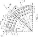
- a quadrant of a second electric drive motor 201 is shown in Figure 4 .
- the second electric drive motor 201 is similar to the first electric drive motor 101 and like reference numerals will be used for like features, albeit incremented by 100 for clarity.
- the second electric drive motor 201 is a permanent magnet synchronous motor comprising a rotor 202 and a stator. An air gap is maintained between the rotor 202 and the stator.
- the rotor 202 is made up of a plurality of laminations of a ferromagnetic material to form a rotor iron.
- the rotor 202 comprises first magnets 204, second magnets 205 and third magnets 212 arranged in first, second and third layers L1, L2, L3.
- the first, second and third magnets 204, 205, 212 are embedded in the rotor 202 to form a plurality of poles 206.
- the rotor 202 comprises eight (8) poles 206a-h.
- the first, second and third magnets 204, 205, 212 are permanent magnets (PM) and generate a magnetic flux.
- the stator comprises a plurality of slots extending radially inwardly to support coil windings. In the present arrangement, the stator comprises forty-eight (48) slots such that there are six (6) slots for each pole 206. By energising the coil winding, a torque is generated to drive the rotor 202.
- the poles 206a-h have the same general configuration. For the sake of brevity, only a first pole 206a will be described herein.
- a reference frame comprising a d-axis and a q-axis will be used in the description of the first pole 206a. More particularly, the reference frame comprises a "+q-axis" and a "-q-axis" corresponding to the lateral boundaries of the first pole 206a.
- the first, second and third magnets 204, 205, 212 are centred on the d-axis of the first pole 206a and are arranged substantially parallel to each other.
- the first pole 206a comprises first, second and third primary flux barriers 209, 210, 213 formed in the rotor 202.
- the first, second and third primary flux barriers 209, 210, 213 are provided to ensure the appropriate flux density distribution at the lateral boundaries of the poles 206a-h (i.e. the "+q axis" and a "-q axis").
- the first, second and third primary flux barriers 209, 210, 213 are air-filled cavities formed in the rotor 202.
- the first, second and third primary flux barriers 209, 210, 213 are elongated and extend at an acute angle relative to the d-axis in a symmetrical configuration.
- the first primary flux barriers 209-1, 209-2 are disposed on respective sides of the first magnet 204; and the second primary flux barriers 210-1, 210-2 are disposed on respective sides of the second magnet 205; and the third primary flux barriers 213-1, 213-2 are disposed on respective sides of the third magnet 212.
- the first, second and third primary flux barriers 209, 210, 213 are through holes formed within the rotor 202 such that the outer surface of the rotor 202 is continuous.
- the first, second and third primary flux barriers 209, 210, 213 can be configured to reduce ripple and voltage harmonics of the second electric drive motor 201.
- the first angular period ⁇ 1 between the first, second and third primary flux barriers 209, 210, 213 is selected to disrupt first and second torque harmonics.
- the possible torque harmonic components for the second electric drive motor 201 are the 6 th , 12 th , 18 th and 24 th harmonics.
- first and second of said torque harmonics can be disrupted by calculating the first angular period ⁇ 1 in dependence on an arithmetical average n 2 of the order numbers of the first and second torque harmonics.
- the first angular period ⁇ 1 between the adjacent primary and secondary flux barriers 209, 210 can be determined by applying equation (2) outlined above.
- the first pole 206a has a pole step ⁇ of 45°.
- the average order number n 2 is calculated as nine (9) to disrupt the 6 th and 12 th torque harmonics.
- the first angular period ⁇ 1 between the first, second and third primary flux barriers 209, 210, 213 is calculated as 5°.
- the first angular period ⁇ 1 is measured between corresponding lateral edges of the adjacent flux barriers 209, 210, 213.
Landscapes
- Engineering & Computer Science (AREA)
- Power Engineering (AREA)
- Permanent Field Magnets Of Synchronous Machinery (AREA)
- Iron Core Of Rotating Electric Machines (AREA)
- Permanent Magnet Type Synchronous Machine (AREA)
- Electric Propulsion And Braking For Vehicles (AREA)
Claims (13)
- Elektrischer Antriebsmotor (101) für ein Fahrzeug, wobei der elektrische Antriebsmotor umfasst:einen Stator (103);einen Rotor (102) mit mehreren Polen (106), wobei jeder Pol umfasst:mindestens einen ersten Permanentmagneten (104), der symmetrisch um eine d-Achse des Pols in einer ersten Schicht angeordnet ist;mindestens einen zweiten Permanentmagneten, der symmetrisch um die d-Achse des Pols in einer zweiten Schicht angeordnet ist, die radial von der ersten Schicht getrennt ist; undmehrere Flussbarrieren (109), die erste und zweite primäre Flussbarrieren umfassen, um mindestens eine Drehmomentharmonische n-ter Ordnung des elektrischen Antriebsmotors zu unterbrechen;wobei die mehreren Flussbarrieren ein Paar von ersten primären Flussbarrieren umfassen, die dem ersten Permanentmagneten zugeordnet sind und symmetrisch um die d-Achse angeordnet sind, und ein Paar von zweiten primären Flussbarrieren, die dem mindestens einen zweiten Permanentmagneten zugeordnet sind und symmetrisch um die d-Achse angeordnet sind;wobei an radial äußeren Enden der Flussbarrieren, proximal zu einer Außenfläche des Rotors, eine erste Winkelperiode ξ1 zwischen entsprechenden Seitenkanten benachbarter erster und zweiter primärer Flussbarrieren der mehreren Flussbarrieren definiert ist durch:wobei:
 ξ1 die erste Winkelperiode ist;τ die Polstufe ist, die die Winkelausdehnung jedes Rotorpols umfasst; undn 1 eine Ordnungszahl einer zu unterbrechenden Drehmomentharmonischen ist.
 - Elektrischer Antriebsmotor nach Anspruch 1, wobei die erste und die zweite primäre Flussbarriere auf jeder Seite des Pols durch die erste Winkelperiode ξ1 voneinander getrennt sind.
- Elektrischer Antriebsmotor nach Anspruch 1 oder Anspruch 2, wobei der Stator zweiundsiebzig (72) Schlitze aufweist und der Rotor acht (8) Pole aufweist; und
die Ordnungszahl n 1 sechs (6) ist, so dass zumindest die Drehmomentharmonische der sechsten (6-ten) Ordnung unterbrochen ist. - Elektrischer Antriebsmotor (101) für ein Fahrzeug, wobei der elektrische Antriebsmotor umfasst:einen Stator (103);einen Rotor (102) mit mehreren Polen (106), wobei jeder Pol umfasst:mindestens einen ersten Permanentmagneten (104), der symmetrisch um eine d-Achse des Pols in einer ersten Schicht angeordnet ist;mindestens einen zweiten Permanentmagneten, der symmetrisch um die d-Achse des Pols in einer zweiten Schicht angeordnet ist, die radial von der ersten Schicht getrennt ist; undmehrere Flussbarrieren (109), die erste und zweite primäre Flussbarrieren umfassen, um mindestens eine Drehmomentharmonische n-ter Ordnung des elektrischen Antriebsmotors zu unterbrechen;wobei die mehreren Flussbarrieren ein Paar von ersten primären Flussbarrieren umfassen, die dem ersten Permanentmagneten zugeordnet sind und symmetrisch um die d-Achse angeordnet sind, und ein Paar von zweiten primären Flussbarrieren, die dem mindestens einen zweiten Permanentmagneten zugeordnet sind und symmetrisch um die d-Achse angeordnet sind;wobei an radial äußeren Enden der Flussbarrieren, proximal zu einer Außenfläche des Rotors, eine erste Winkelperiode ξ1 zwischen entsprechenden Seitenkanten benachbarter erster und zweiter primärer Flussbarrieren der mehreren Flussbarrieren definiert ist durch:wobei:
 ξ1 die erste Winkelperiode ist;τ die Polstufe ist, die die Winkelausdehnung jedes Rotorpols umfasst; undn2 eine durchschnittliche Ordnungszahl der ersten und zweiten zu unterbrechenden Drehmomentharmonischen ist.
 - Elektrischer Antriebsmotor nach Anspruch 4, wobei die erste und die zweite primäre Flussbarriere auf jeder Seite des Pols durch die erste Winkelperiode ξ1 voneinander getrennt sind.
- Elektrischer Antriebsmotor nach Anspruch 4 oder Anspruch 5, wobei der Stator achtundvierzig (48) Schlitze aufweist und der Rotor acht (8) Pole aufweist; und
die durchschnittliche Ordnungszahl n2 neun (9) ist, so dass zumindest die sechsten (6-ten) und zwölften (12-ten) Drehmomentharmonischen unterbrochen werden. - Elektrischer Antriebsmotor nach einem der vorhergehenden Ansprüche, wobei die mehreren Flussbarrieren mehrere sekundäre Flussbarrieren umfassen.
- Elektrischer Antriebsmotor nach Anspruch 7, wobei die Winkelperiode zwischen benachbarten primären und sekundären Flussbarrieren im Wesentlichen gleich der ersten Winkelperiode ξ1 ist.
- Elektrischer Antriebsmotor nach Anspruch 7 oder Anspruch 8, umfassend eine der sekundären Flussbarrieren, die auf der d-Achse des Pols angeordnet sind; und/oder
eine der sekundären Flussbarrieren, die auf einer q-Achse des Pols angeordnet sind. - Elektrischer Antriebsmotor nach einem der Ansprüche 7, 8 oder 9, wobei die sekundären Flussbarrieren jeweils eine kreisförmige Öffnung umfassen.
- Elektrischer Antriebsmotor nach einem der Ansprüche 7 bis 10, wobei eine oder mehrere der sekundären Flussbarrieren zwischen dem ersten Permanentmagneten und der radialen Außenfläche des Rotors angeordnet sind.
- Elektrischer Antriebsmotor nach einem der vorhergehenden Ansprüche, wobei die Flussbarrieren mit Luft gefüllt sind oder mit einem anderen Material gefüllt sind, dessen elektrische Leitfähigkeit und magnetische Permeabilität den entsprechenden Parametern in Luft gleichen.
- Fahrzeug mit einem elektrischen Antriebsmotor nach einem der vorhergehenden Ansprüche.
Applications Claiming Priority (2)
| Application Number | Priority Date | Filing Date | Title |
|---|---|---|---|
| GBGB1510273.4A GB201510273D0 (en) | 2015-06-12 | 2015-06-12 | Electric drive motor |
| PCT/EP2016/063061 WO2016198468A1 (en) | 2015-06-12 | 2016-06-08 | Electric drive motor |
Publications (2)
| Publication Number | Publication Date |
|---|---|
| EP3308450A1 EP3308450A1 (de) | 2018-04-18 |
| EP3308450B1 true EP3308450B1 (de) | 2021-01-27 |
Family
ID=53784576
Family Applications (1)
| Application Number | Title | Priority Date | Filing Date |
|---|---|---|---|
| EP16727718.5A Active EP3308450B1 (de) | 2015-06-12 | 2016-06-08 | Elektrischen antriebsmotor |
Country Status (6)
| Country | Link |
|---|---|
| US (1) | US10778054B2 (de) |
| EP (1) | EP3308450B1 (de) |
| JP (3) | JP2018516056A (de) |
| CN (1) | CN107683556B (de) |
| GB (2) | GB201510273D0 (de) |
| WO (1) | WO2016198468A1 (de) |
Families Citing this family (13)
| Publication number | Priority date | Publication date | Assignee | Title |
|---|---|---|---|---|
| GB201510273D0 (en) * | 2015-06-12 | 2015-07-29 | Jaguar Land Rover Ltd | Electric drive motor |
| US10432043B2 (en) * | 2016-12-16 | 2019-10-01 | Ford Global Technologies, Llc | Slotted rotor-bridge for electrical machines |
| CN106816976A (zh) * | 2017-03-31 | 2017-06-09 | 苏州汇川联合动力系统有限公司 | 转子冲片、电机转子及永磁同步电机 |
| FR3071371B1 (fr) * | 2017-09-18 | 2019-09-13 | IFP Energies Nouvelles | Geometrie de ponts magnetiques d'un rotor de machine electrique |
| FR3084535B1 (fr) * | 2018-07-24 | 2020-07-17 | IFP Energies Nouvelles | Rotor de machine electrique avec poles asymetriques |
| WO2019234770A1 (en) * | 2018-06-07 | 2019-12-12 | Mavel S.R.L. | Rotor for an electrical machine and electrical machine comprising said rotor |
| GB2574450A (en) * | 2018-06-07 | 2019-12-11 | Continental Automotive Gmbh | Rotor, electric machine and vehicle |
| CN110620456B (zh) * | 2018-06-20 | 2025-01-10 | 广东美芝制冷设备有限公司 | 转子铁芯、永磁电机及压缩机 |
| DE102018128146A1 (de) * | 2018-11-09 | 2020-05-14 | Brusa Elektronik Ag | Rotor für einen Synchron-Antriebsmotor |
| US10797546B2 (en) * | 2019-01-08 | 2020-10-06 | Borgwarner Inc. | Interior permanent magnet electric machine with flux distributing voids |
| FR3094583B1 (fr) * | 2019-03-29 | 2021-03-12 | Ifp Energies Now | Rotor de machine électrique avec pôles asymétriques et aimants latéraux |
| DE102020214035A1 (de) | 2020-11-09 | 2022-05-12 | Robert Bosch Gesellschaft mit beschränkter Haftung | Rotor einer elektrischen Maschine mit mehrschichtiger Permanentmagnetanordnung |
| WO2025191619A1 (en) | 2024-03-13 | 2025-09-18 | Mavel edt S.p.A. | Rotor for electric machine and electric machine comprising such rotor |
Citations (1)
| Publication number | Priority date | Publication date | Assignee | Title |
|---|---|---|---|---|
| CN102916544B (zh) * | 2011-08-01 | 2015-06-10 | 珠海格力节能环保制冷技术研究中心有限公司 | 电机转子结构及永磁同步电机和变频压缩机 |
Family Cites Families (22)
| Publication number | Priority date | Publication date | Assignee | Title |
|---|---|---|---|---|
| JPH11187597A (ja) * | 1997-12-19 | 1999-07-09 | Matsushita Electric Ind Co Ltd | 永久磁石埋め込みロータ |
| US6815859B2 (en) | 2001-03-07 | 2004-11-09 | Aisin Seiki Kabushiki Kaisha | Synchronous reluctance motor |
| JP4120208B2 (ja) | 2001-11-20 | 2008-07-16 | アイシン精機株式会社 | 永久磁石型同期機 |
| JP2006314152A (ja) * | 2005-05-06 | 2006-11-16 | Nissan Motor Co Ltd | 永久磁石型電動機 |
| JP2007097387A (ja) | 2005-08-31 | 2007-04-12 | Toshiba Corp | 回転電機 |
| JP4131276B2 (ja) * | 2005-12-19 | 2008-08-13 | ダイキン工業株式会社 | 電動機並びにその回転子及び回転子用磁心 |
| KR101065991B1 (ko) * | 2007-02-21 | 2011-09-19 | 미쓰비시덴키 가부시키가이샤 | 영구자석 동기 전동기 및 밀폐형 압축기 |
| US20100079023A1 (en) | 2007-06-04 | 2010-04-01 | Sei-Joo Jang | Repulsive force conversion drives and centrifugal force conversion |
| US20090224624A1 (en) | 2008-03-06 | 2009-09-10 | Ajith Kuttannair Kumar | Rotor structure for interior permanent magnet electromotive machine |
| US7902710B2 (en) * | 2008-10-01 | 2011-03-08 | Caterpillar Inc. | Electric machine |
| JP4821902B2 (ja) * | 2009-09-30 | 2011-11-24 | ダイキン工業株式会社 | モータ及びそれを備えたモータ駆動システム |
| JP2011097783A (ja) * | 2009-10-30 | 2011-05-12 | Aisin Aw Co Ltd | 回転電機のロータ |
| JP2011147313A (ja) * | 2010-01-18 | 2011-07-28 | Mitsubishi Electric Corp | 電動機および圧縮機並びに冷凍サイクル装置 |
| CN102754308B (zh) | 2010-02-08 | 2015-04-22 | 三菱电机株式会社 | 永久磁铁埋入型马达的转子及鼓风机和压缩机 |
| JP5862048B2 (ja) * | 2010-05-13 | 2016-02-16 | 株式会社デンソー | 回転電機の回転子 |
| JP5516739B2 (ja) * | 2010-07-27 | 2014-06-11 | 日産自動車株式会社 | 電動機用ロータ |
| JP5478461B2 (ja) * | 2010-11-09 | 2014-04-23 | 三菱電機株式会社 | 電動機及び圧縮機 |
| EP2797208B1 (de) * | 2011-12-23 | 2022-08-31 | Mitsubishi Electric Corporation | Dauermagnetmotor |
| WO2014068655A1 (ja) * | 2012-10-30 | 2014-05-08 | 三菱電機株式会社 | 永久磁石埋込型電動機及びそれを備えた冷凍空調装置 |
| US9985507B2 (en) * | 2013-04-22 | 2018-05-29 | Mitsubishi Electric Corporation | Permanent magnet type motor |
| GB201510273D0 (en) * | 2015-06-12 | 2015-07-29 | Jaguar Land Rover Ltd | Electric drive motor |
| CN105958689B (zh) | 2016-06-08 | 2018-08-07 | 珠海格力节能环保制冷技术研究中心有限公司 | 铁心结构、转子组件及永磁电机 |
-
2015
- 2015-06-12 GB GBGB1510273.4A patent/GB201510273D0/en not_active Ceased
-
2016
- 2016-06-08 GB GB1610012.5A patent/GB2540859B/en not_active Expired - Fee Related
- 2016-06-08 EP EP16727718.5A patent/EP3308450B1/de active Active
- 2016-06-08 CN CN201680025022.0A patent/CN107683556B/zh active Active
- 2016-06-08 JP JP2017560177A patent/JP2018516056A/ja active Pending
- 2016-06-08 US US15/570,863 patent/US10778054B2/en active Active
- 2016-06-08 WO PCT/EP2016/063061 patent/WO2016198468A1/en not_active Ceased
-
2019
- 2019-12-06 JP JP2019220969A patent/JP2020043760A/ja active Pending
-
2022
- 2022-03-16 JP JP2022041463A patent/JP2022084761A/ja active Pending
Patent Citations (1)
| Publication number | Priority date | Publication date | Assignee | Title |
|---|---|---|---|---|
| CN102916544B (zh) * | 2011-08-01 | 2015-06-10 | 珠海格力节能环保制冷技术研究中心有限公司 | 电机转子结构及永磁同步电机和变频压缩机 |
Also Published As
| Publication number | Publication date |
|---|---|
| CN107683556B (zh) | 2020-11-03 |
| EP3308450A1 (de) | 2018-04-18 |
| JP2022084761A (ja) | 2022-06-07 |
| CN107683556A (zh) | 2018-02-09 |
| GB2540859A (en) | 2017-02-01 |
| JP2018516056A (ja) | 2018-06-14 |
| WO2016198468A1 (en) | 2016-12-15 |
| US10778054B2 (en) | 2020-09-15 |
| JP2020043760A (ja) | 2020-03-19 |
| GB201610012D0 (en) | 2016-07-20 |
| GB201510273D0 (en) | 2015-07-29 |
| US20180138764A1 (en) | 2018-05-17 |
| GB2540859B (en) | 2019-07-10 |
Similar Documents
| Publication | Publication Date | Title |
|---|---|---|
| GB2540859B (en) | Electric drive motor | |
| EP3534496B1 (de) | Dauermagnetmotor | |
| EP2712058B1 (de) | Elektrische drehmaschine mit permanentmagnet | |
| US20170040854A1 (en) | Rotor for a rotary electric machine | |
| US20130270958A1 (en) | Rotary electric machine | |
| JP7314789B2 (ja) | 埋込磁石形回転子および回転電機 | |
| JP6821022B2 (ja) | 回転電機の回転子 | |
| US9917481B2 (en) | Synchronous reluctance machine | |
| US20160285328A1 (en) | Rotor, motor including the same, and method of manufacturing the same | |
| JP2017070170A (ja) | 永久磁石式回転子および永久磁石式回転電機 | |
| US20190190328A1 (en) | Line-start synchronous reluctance motor and rotor thereof | |
| CN106165262A (zh) | 用于旋转电机的转子 | |
| JP2000245085A (ja) | モータ | |
| CN109643919A (zh) | 旋转电机 | |
| EP3926798A1 (de) | Aufbau eines elektrischen direktstart-synchronreluktanzmotorrotors, elektromotor und verdichter | |
| JP6497173B2 (ja) | スイッチトリラクタンス回転機 | |
| KR20100005468A (ko) | 교류 모터용 영구자석 회전자 | |
| JP7132729B2 (ja) | 回転電機 | |
| JP5839298B2 (ja) | モータ | |
| JP6990014B2 (ja) | 回転電機 | |
| JP2021048670A (ja) | 磁石部材、回転電機及び磁石部材の製造方法 | |
| KR20120134526A (ko) | 스위치드 릴럭턴스 모터 | |
| JP2017158344A (ja) | 回転電機 | |
| JP6558157B2 (ja) | 回転電機 | |
| KR20120057489A (ko) | 세그먼트형 스위치드 릴럭턴스 모터 |
Legal Events
| Date | Code | Title | Description |
|---|---|---|---|
| STAA | Information on the status of an ep patent application or granted ep patent |
Free format text: STATUS: THE INTERNATIONAL PUBLICATION HAS BEEN MADE |
|
| PUAI | Public reference made under article 153(3) epc to a published international application that has entered the european phase |
Free format text: ORIGINAL CODE: 0009012 |
|
| STAA | Information on the status of an ep patent application or granted ep patent |
Free format text: STATUS: REQUEST FOR EXAMINATION WAS MADE |
|
| 17P | Request for examination filed |
Effective date: 20180112 |
|
| AK | Designated contracting states |
Kind code of ref document: A1 Designated state(s): AL AT BE BG CH CY CZ DE DK EE ES FI FR GB GR HR HU IE IS IT LI LT LU LV MC MK MT NL NO PL PT RO RS SE SI SK SM TR |
|
| AX | Request for extension of the european patent |
Extension state: BA ME |
|
| DAV | Request for validation of the european patent (deleted) | ||
| DAX | Request for extension of the european patent (deleted) | ||
| STAA | Information on the status of an ep patent application or granted ep patent |
Free format text: STATUS: EXAMINATION IS IN PROGRESS |
|
| 17Q | First examination report despatched |
Effective date: 20190905 |
|
| GRAP | Despatch of communication of intention to grant a patent |
Free format text: ORIGINAL CODE: EPIDOSNIGR1 |
|
| STAA | Information on the status of an ep patent application or granted ep patent |
Free format text: STATUS: GRANT OF PATENT IS INTENDED |
|
| INTG | Intention to grant announced |
Effective date: 20200320 |
|
| GRAJ | Information related to disapproval of communication of intention to grant by the applicant or resumption of examination proceedings by the epo deleted |
Free format text: ORIGINAL CODE: EPIDOSDIGR1 |
|
| STAA | Information on the status of an ep patent application or granted ep patent |
Free format text: STATUS: EXAMINATION IS IN PROGRESS |
|
| GRAP | Despatch of communication of intention to grant a patent |
Free format text: ORIGINAL CODE: EPIDOSNIGR1 |
|
| STAA | Information on the status of an ep patent application or granted ep patent |
Free format text: STATUS: GRANT OF PATENT IS INTENDED |
|
| INTC | Intention to grant announced (deleted) | ||
| INTG | Intention to grant announced |
Effective date: 20200820 |
|
| GRAS | Grant fee paid |
Free format text: ORIGINAL CODE: EPIDOSNIGR3 |
|
| GRAA | (expected) grant |
Free format text: ORIGINAL CODE: 0009210 |
|
| STAA | Information on the status of an ep patent application or granted ep patent |
Free format text: STATUS: THE PATENT HAS BEEN GRANTED |
|
| AK | Designated contracting states |
Kind code of ref document: B1 Designated state(s): AL AT BE BG CH CY CZ DE DK EE ES FI FR GB GR HR HU IE IS IT LI LT LU LV MC MK MT NL NO PL PT RO RS SE SI SK SM TR |
|
| REG | Reference to a national code |
Ref country code: GB Ref legal event code: FG4D |
|
| REG | Reference to a national code |
Ref country code: CH Ref legal event code: EP |
|
| REG | Reference to a national code |
Ref country code: AT Ref legal event code: REF Ref document number: 1359212 Country of ref document: AT Kind code of ref document: T Effective date: 20210215 |
|
| REG | Reference to a national code |
Ref country code: IE Ref legal event code: FG4D |
|
| REG | Reference to a national code |
Ref country code: DE Ref legal event code: R096 Ref document number: 602016052049 Country of ref document: DE |
|
| REG | Reference to a national code |
Ref country code: NL Ref legal event code: MP Effective date: 20210127 |
|
| REG | Reference to a national code |
Ref country code: LT Ref legal event code: MG9D |
|
| REG | Reference to a national code |
Ref country code: AT Ref legal event code: MK05 Ref document number: 1359212 Country of ref document: AT Kind code of ref document: T Effective date: 20210127 |
|
| PG25 | Lapsed in a contracting state [announced via postgrant information from national office to epo] |
Ref country code: BG Free format text: LAPSE BECAUSE OF FAILURE TO SUBMIT A TRANSLATION OF THE DESCRIPTION OR TO PAY THE FEE WITHIN THE PRESCRIBED TIME-LIMIT Effective date: 20210427 Ref country code: LT Free format text: LAPSE BECAUSE OF FAILURE TO SUBMIT A TRANSLATION OF THE DESCRIPTION OR TO PAY THE FEE WITHIN THE PRESCRIBED TIME-LIMIT Effective date: 20210127 Ref country code: FI Free format text: LAPSE BECAUSE OF FAILURE TO SUBMIT A TRANSLATION OF THE DESCRIPTION OR TO PAY THE FEE WITHIN THE PRESCRIBED TIME-LIMIT Effective date: 20210127 Ref country code: GR Free format text: LAPSE BECAUSE OF FAILURE TO SUBMIT A TRANSLATION OF THE DESCRIPTION OR TO PAY THE FEE WITHIN THE PRESCRIBED TIME-LIMIT Effective date: 20210428 Ref country code: HR Free format text: LAPSE BECAUSE OF FAILURE TO SUBMIT A TRANSLATION OF THE DESCRIPTION OR TO PAY THE FEE WITHIN THE PRESCRIBED TIME-LIMIT Effective date: 20210127 Ref country code: NO Free format text: LAPSE BECAUSE OF FAILURE TO SUBMIT A TRANSLATION OF THE DESCRIPTION OR TO PAY THE FEE WITHIN THE PRESCRIBED TIME-LIMIT Effective date: 20210427 Ref country code: PT Free format text: LAPSE BECAUSE OF FAILURE TO SUBMIT A TRANSLATION OF THE DESCRIPTION OR TO PAY THE FEE WITHIN THE PRESCRIBED TIME-LIMIT Effective date: 20210527 |
|
| PG25 | Lapsed in a contracting state [announced via postgrant information from national office to epo] |
Ref country code: SE Free format text: LAPSE BECAUSE OF FAILURE TO SUBMIT A TRANSLATION OF THE DESCRIPTION OR TO PAY THE FEE WITHIN THE PRESCRIBED TIME-LIMIT Effective date: 20210127 Ref country code: AT Free format text: LAPSE BECAUSE OF FAILURE TO SUBMIT A TRANSLATION OF THE DESCRIPTION OR TO PAY THE FEE WITHIN THE PRESCRIBED TIME-LIMIT Effective date: 20210127 Ref country code: RS Free format text: LAPSE BECAUSE OF FAILURE TO SUBMIT A TRANSLATION OF THE DESCRIPTION OR TO PAY THE FEE WITHIN THE PRESCRIBED TIME-LIMIT Effective date: 20210127 Ref country code: LV Free format text: LAPSE BECAUSE OF FAILURE TO SUBMIT A TRANSLATION OF THE DESCRIPTION OR TO PAY THE FEE WITHIN THE PRESCRIBED TIME-LIMIT Effective date: 20210127 Ref country code: PL Free format text: LAPSE BECAUSE OF FAILURE TO SUBMIT A TRANSLATION OF THE DESCRIPTION OR TO PAY THE FEE WITHIN THE PRESCRIBED TIME-LIMIT Effective date: 20210127 |
|
| PG25 | Lapsed in a contracting state [announced via postgrant information from national office to epo] |
Ref country code: IS Free format text: LAPSE BECAUSE OF FAILURE TO SUBMIT A TRANSLATION OF THE DESCRIPTION OR TO PAY THE FEE WITHIN THE PRESCRIBED TIME-LIMIT Effective date: 20210527 |
|
| REG | Reference to a national code |
Ref country code: DE Ref legal event code: R097 Ref document number: 602016052049 Country of ref document: DE |
|
| PG25 | Lapsed in a contracting state [announced via postgrant information from national office to epo] |
Ref country code: SM Free format text: LAPSE BECAUSE OF FAILURE TO SUBMIT A TRANSLATION OF THE DESCRIPTION OR TO PAY THE FEE WITHIN THE PRESCRIBED TIME-LIMIT Effective date: 20210127 Ref country code: EE Free format text: LAPSE BECAUSE OF FAILURE TO SUBMIT A TRANSLATION OF THE DESCRIPTION OR TO PAY THE FEE WITHIN THE PRESCRIBED TIME-LIMIT Effective date: 20210127 Ref country code: CZ Free format text: LAPSE BECAUSE OF FAILURE TO SUBMIT A TRANSLATION OF THE DESCRIPTION OR TO PAY THE FEE WITHIN THE PRESCRIBED TIME-LIMIT Effective date: 20210127 |
|
| PG25 | Lapsed in a contracting state [announced via postgrant information from national office to epo] |
Ref country code: DK Free format text: LAPSE BECAUSE OF FAILURE TO SUBMIT A TRANSLATION OF THE DESCRIPTION OR TO PAY THE FEE WITHIN THE PRESCRIBED TIME-LIMIT Effective date: 20210127 Ref country code: SK Free format text: LAPSE BECAUSE OF FAILURE TO SUBMIT A TRANSLATION OF THE DESCRIPTION OR TO PAY THE FEE WITHIN THE PRESCRIBED TIME-LIMIT Effective date: 20210127 Ref country code: RO Free format text: LAPSE BECAUSE OF FAILURE TO SUBMIT A TRANSLATION OF THE DESCRIPTION OR TO PAY THE FEE WITHIN THE PRESCRIBED TIME-LIMIT Effective date: 20210127 |
|
| PLBE | No opposition filed within time limit |
Free format text: ORIGINAL CODE: 0009261 |
|
| STAA | Information on the status of an ep patent application or granted ep patent |
Free format text: STATUS: NO OPPOSITION FILED WITHIN TIME LIMIT |
|
| 26N | No opposition filed |
Effective date: 20211028 |
|
| PG25 | Lapsed in a contracting state [announced via postgrant information from national office to epo] |
Ref country code: AL Free format text: LAPSE BECAUSE OF FAILURE TO SUBMIT A TRANSLATION OF THE DESCRIPTION OR TO PAY THE FEE WITHIN THE PRESCRIBED TIME-LIMIT Effective date: 20210127 Ref country code: MC Free format text: LAPSE BECAUSE OF FAILURE TO SUBMIT A TRANSLATION OF THE DESCRIPTION OR TO PAY THE FEE WITHIN THE PRESCRIBED TIME-LIMIT Effective date: 20210127 Ref country code: ES Free format text: LAPSE BECAUSE OF FAILURE TO SUBMIT A TRANSLATION OF THE DESCRIPTION OR TO PAY THE FEE WITHIN THE PRESCRIBED TIME-LIMIT Effective date: 20210127 |
|
| REG | Reference to a national code |
Ref country code: CH Ref legal event code: PL |
|
| PG25 | Lapsed in a contracting state [announced via postgrant information from national office to epo] |
Ref country code: SI Free format text: LAPSE BECAUSE OF FAILURE TO SUBMIT A TRANSLATION OF THE DESCRIPTION OR TO PAY THE FEE WITHIN THE PRESCRIBED TIME-LIMIT Effective date: 20210127 |
|
| REG | Reference to a national code |
Ref country code: BE Ref legal event code: MM Effective date: 20210630 |
|
| PG25 | Lapsed in a contracting state [announced via postgrant information from national office to epo] |
Ref country code: LU Free format text: LAPSE BECAUSE OF NON-PAYMENT OF DUE FEES Effective date: 20210608 |
|
| PG25 | Lapsed in a contracting state [announced via postgrant information from national office to epo] |
Ref country code: LI Free format text: LAPSE BECAUSE OF NON-PAYMENT OF DUE FEES Effective date: 20210630 Ref country code: IT Free format text: LAPSE BECAUSE OF FAILURE TO SUBMIT A TRANSLATION OF THE DESCRIPTION OR TO PAY THE FEE WITHIN THE PRESCRIBED TIME-LIMIT Effective date: 20210127 Ref country code: IE Free format text: LAPSE BECAUSE OF NON-PAYMENT OF DUE FEES Effective date: 20210608 Ref country code: CH Free format text: LAPSE BECAUSE OF NON-PAYMENT OF DUE FEES Effective date: 20210630 |
|
| PG25 | Lapsed in a contracting state [announced via postgrant information from national office to epo] |
Ref country code: IS Free format text: LAPSE BECAUSE OF FAILURE TO SUBMIT A TRANSLATION OF THE DESCRIPTION OR TO PAY THE FEE WITHIN THE PRESCRIBED TIME-LIMIT Effective date: 20210527 |
|
| PG25 | Lapsed in a contracting state [announced via postgrant information from national office to epo] |
Ref country code: BE Free format text: LAPSE BECAUSE OF NON-PAYMENT OF DUE FEES Effective date: 20210630 |
|
| PG25 | Lapsed in a contracting state [announced via postgrant information from national office to epo] |
Ref country code: NL Free format text: LAPSE BECAUSE OF NON-PAYMENT OF DUE FEES Effective date: 20210127 Ref country code: CY Free format text: LAPSE BECAUSE OF FAILURE TO SUBMIT A TRANSLATION OF THE DESCRIPTION OR TO PAY THE FEE WITHIN THE PRESCRIBED TIME-LIMIT Effective date: 20210127 |
|
| P01 | Opt-out of the competence of the unified patent court (upc) registered |
Effective date: 20230528 |
|
| PG25 | Lapsed in a contracting state [announced via postgrant information from national office to epo] |
Ref country code: HU Free format text: LAPSE BECAUSE OF FAILURE TO SUBMIT A TRANSLATION OF THE DESCRIPTION OR TO PAY THE FEE WITHIN THE PRESCRIBED TIME-LIMIT; INVALID AB INITIO Effective date: 20160608 |
|
| PG25 | Lapsed in a contracting state [announced via postgrant information from national office to epo] |
Ref country code: MK Free format text: LAPSE BECAUSE OF FAILURE TO SUBMIT A TRANSLATION OF THE DESCRIPTION OR TO PAY THE FEE WITHIN THE PRESCRIBED TIME-LIMIT Effective date: 20210127 |
|
| PG25 | Lapsed in a contracting state [announced via postgrant information from national office to epo] |
Ref country code: MT Free format text: LAPSE BECAUSE OF FAILURE TO SUBMIT A TRANSLATION OF THE DESCRIPTION OR TO PAY THE FEE WITHIN THE PRESCRIBED TIME-LIMIT Effective date: 20210127 |
|
| PGFP | Annual fee paid to national office [announced via postgrant information from national office to epo] |
Ref country code: DE Payment date: 20250618 Year of fee payment: 10 |
|
| PGFP | Annual fee paid to national office [announced via postgrant information from national office to epo] |
Ref country code: GB Payment date: 20250618 Year of fee payment: 10 |
|
| PGFP | Annual fee paid to national office [announced via postgrant information from national office to epo] |
Ref country code: FR Payment date: 20250625 Year of fee payment: 10 |
|
| PG25 | Lapsed in a contracting state [announced via postgrant information from national office to epo] |
Ref country code: TR Free format text: LAPSE BECAUSE OF FAILURE TO SUBMIT A TRANSLATION OF THE DESCRIPTION OR TO PAY THE FEE WITHIN THE PRESCRIBED TIME-LIMIT Effective date: 20210127 |