EP3307585B1 - Batterieaustauschsystem - Google Patents
Batterieaustauschsystem Download PDFInfo
- Publication number
- EP3307585B1 EP3307585B1 EP16728932.1A EP16728932A EP3307585B1 EP 3307585 B1 EP3307585 B1 EP 3307585B1 EP 16728932 A EP16728932 A EP 16728932A EP 3307585 B1 EP3307585 B1 EP 3307585B1
- Authority
- EP
- European Patent Office
- Prior art keywords
- battery
- battery block
- block
- lift
- dock
- Prior art date
- Legal status (The legal status is an assumption and is not a legal conclusion. Google has not performed a legal analysis and makes no representation as to the accuracy of the status listed.)
- Active
Links
- 230000000903 blocking effect Effects 0.000 claims description 24
- 230000002093 peripheral effect Effects 0.000 claims description 20
- 238000004891 communication Methods 0.000 description 7
- 239000011324 bead Substances 0.000 description 6
- 238000000034 method Methods 0.000 description 6
- 229920006362 Teflon® Polymers 0.000 description 4
- 239000011248 coating agent Substances 0.000 description 4
- 238000000576 coating method Methods 0.000 description 4
- 238000001816 cooling Methods 0.000 description 4
- 238000010438 heat treatment Methods 0.000 description 4
- 239000002184 metal Substances 0.000 description 4
- 229910052751 metal Inorganic materials 0.000 description 4
- 238000005096 rolling process Methods 0.000 description 4
- 230000000712 assembly Effects 0.000 description 3
- 238000000429 assembly Methods 0.000 description 3
- 238000003780 insertion Methods 0.000 description 3
- 230000037431 insertion Effects 0.000 description 3
- 239000003831 antifriction material Substances 0.000 description 2
- 230000000295 complement effect Effects 0.000 description 2
- 239000002783 friction material Substances 0.000 description 2
- 229920001296 polysiloxane Polymers 0.000 description 2
- 238000012546 transfer Methods 0.000 description 2
- 229910000831 Steel Inorganic materials 0.000 description 1
- HCHKCACWOHOZIP-UHFFFAOYSA-N Zinc Chemical compound [Zn] HCHKCACWOHOZIP-UHFFFAOYSA-N 0.000 description 1
- 230000000694 effects Effects 0.000 description 1
- 230000002349 favourable effect Effects 0.000 description 1
- 230000005294 ferromagnetic effect Effects 0.000 description 1
- 230000001939 inductive effect Effects 0.000 description 1
- 230000003287 optical effect Effects 0.000 description 1
- 238000012545 processing Methods 0.000 description 1
- 239000010959 steel Substances 0.000 description 1
- 229910052725 zinc Inorganic materials 0.000 description 1
- 239000011701 zinc Substances 0.000 description 1
Images


Classifications
-
- B—PERFORMING OPERATIONS; TRANSPORTING
- B60—VEHICLES IN GENERAL
- B60L—PROPULSION OF ELECTRICALLY-PROPELLED VEHICLES; SUPPLYING ELECTRIC POWER FOR AUXILIARY EQUIPMENT OF ELECTRICALLY-PROPELLED VEHICLES; ELECTRODYNAMIC BRAKE SYSTEMS FOR VEHICLES IN GENERAL; MAGNETIC SUSPENSION OR LEVITATION FOR VEHICLES; MONITORING OPERATING VARIABLES OF ELECTRICALLY-PROPELLED VEHICLES; ELECTRIC SAFETY DEVICES FOR ELECTRICALLY-PROPELLED VEHICLES
- B60L53/00—Methods of charging batteries, specially adapted for electric vehicles; Charging stations or on-board charging equipment therefor; Exchange of energy storage elements in electric vehicles
- B60L53/80—Exchanging energy storage elements, e.g. removable batteries
-
- B—PERFORMING OPERATIONS; TRANSPORTING
- B60—VEHICLES IN GENERAL
- B60K—ARRANGEMENT OR MOUNTING OF PROPULSION UNITS OR OF TRANSMISSIONS IN VEHICLES; ARRANGEMENT OR MOUNTING OF PLURAL DIVERSE PRIME-MOVERS IN VEHICLES; AUXILIARY DRIVES FOR VEHICLES; INSTRUMENTATION OR DASHBOARDS FOR VEHICLES; ARRANGEMENTS IN CONNECTION WITH COOLING, AIR INTAKE, GAS EXHAUST OR FUEL SUPPLY OF PROPULSION UNITS IN VEHICLES
- B60K1/00—Arrangement or mounting of electrical propulsion units
- B60K1/04—Arrangement or mounting of electrical propulsion units of the electric storage means for propulsion
-
- B—PERFORMING OPERATIONS; TRANSPORTING
- B60—VEHICLES IN GENERAL
- B60L—PROPULSION OF ELECTRICALLY-PROPELLED VEHICLES; SUPPLYING ELECTRIC POWER FOR AUXILIARY EQUIPMENT OF ELECTRICALLY-PROPELLED VEHICLES; ELECTRODYNAMIC BRAKE SYSTEMS FOR VEHICLES IN GENERAL; MAGNETIC SUSPENSION OR LEVITATION FOR VEHICLES; MONITORING OPERATING VARIABLES OF ELECTRICALLY-PROPELLED VEHICLES; ELECTRIC SAFETY DEVICES FOR ELECTRICALLY-PROPELLED VEHICLES
- B60L50/00—Electric propulsion with power supplied within the vehicle
- B60L50/50—Electric propulsion with power supplied within the vehicle using propulsion power supplied by batteries or fuel cells
- B60L50/60—Electric propulsion with power supplied within the vehicle using propulsion power supplied by batteries or fuel cells using power supplied by batteries
- B60L50/64—Constructional details of batteries specially adapted for electric vehicles
-
- B—PERFORMING OPERATIONS; TRANSPORTING
- B60—VEHICLES IN GENERAL
- B60S—SERVICING, CLEANING, REPAIRING, SUPPORTING, LIFTING, OR MANOEUVRING OF VEHICLES, NOT OTHERWISE PROVIDED FOR
- B60S5/00—Servicing, maintaining, repairing, or refitting of vehicles
- B60S5/06—Supplying batteries to, or removing batteries from, vehicles
-
- B—PERFORMING OPERATIONS; TRANSPORTING
- B66—HOISTING; LIFTING; HAULING
- B66F—HOISTING, LIFTING, HAULING OR PUSHING, NOT OTHERWISE PROVIDED FOR, e.g. DEVICES WHICH APPLY A LIFTING OR PUSHING FORCE DIRECTLY TO THE SURFACE OF A LOAD
- B66F9/00—Devices for lifting or lowering bulky or heavy goods for loading or unloading purposes
- B66F9/06—Devices for lifting or lowering bulky or heavy goods for loading or unloading purposes movable, with their loads, on wheels or the like, e.g. fork-lift trucks
-
- B—PERFORMING OPERATIONS; TRANSPORTING
- B60—VEHICLES IN GENERAL
- B60K—ARRANGEMENT OR MOUNTING OF PROPULSION UNITS OR OF TRANSMISSIONS IN VEHICLES; ARRANGEMENT OR MOUNTING OF PLURAL DIVERSE PRIME-MOVERS IN VEHICLES; AUXILIARY DRIVES FOR VEHICLES; INSTRUMENTATION OR DASHBOARDS FOR VEHICLES; ARRANGEMENTS IN CONNECTION WITH COOLING, AIR INTAKE, GAS EXHAUST OR FUEL SUPPLY OF PROPULSION UNITS IN VEHICLES
- B60K1/00—Arrangement or mounting of electrical propulsion units
- B60K1/04—Arrangement or mounting of electrical propulsion units of the electric storage means for propulsion
- B60K2001/0405—Arrangement or mounting of electrical propulsion units of the electric storage means for propulsion characterised by their position
- B60K2001/0438—Arrangement under the floor
-
- B—PERFORMING OPERATIONS; TRANSPORTING
- B60—VEHICLES IN GENERAL
- B60K—ARRANGEMENT OR MOUNTING OF PROPULSION UNITS OR OF TRANSMISSIONS IN VEHICLES; ARRANGEMENT OR MOUNTING OF PLURAL DIVERSE PRIME-MOVERS IN VEHICLES; AUXILIARY DRIVES FOR VEHICLES; INSTRUMENTATION OR DASHBOARDS FOR VEHICLES; ARRANGEMENTS IN CONNECTION WITH COOLING, AIR INTAKE, GAS EXHAUST OR FUEL SUPPLY OF PROPULSION UNITS IN VEHICLES
- B60K1/00—Arrangement or mounting of electrical propulsion units
- B60K1/04—Arrangement or mounting of electrical propulsion units of the electric storage means for propulsion
- B60K2001/0455—Removal or replacement of the energy storages
- B60K2001/0472—Removal or replacement of the energy storages from below
-
- B—PERFORMING OPERATIONS; TRANSPORTING
- B60—VEHICLES IN GENERAL
- B60Y—INDEXING SCHEME RELATING TO ASPECTS CROSS-CUTTING VEHICLE TECHNOLOGY
- B60Y2200/00—Type of vehicle
- B60Y2200/90—Vehicles comprising electric prime movers
- B60Y2200/91—Electric vehicles
-
- B—PERFORMING OPERATIONS; TRANSPORTING
- B60—VEHICLES IN GENERAL
- B60Y—INDEXING SCHEME RELATING TO ASPECTS CROSS-CUTTING VEHICLE TECHNOLOGY
- B60Y2200/00—Type of vehicle
- B60Y2200/90—Vehicles comprising electric prime movers
- B60Y2200/92—Hybrid vehicles
-
- B—PERFORMING OPERATIONS; TRANSPORTING
- B60—VEHICLES IN GENERAL
- B60Y—INDEXING SCHEME RELATING TO ASPECTS CROSS-CUTTING VEHICLE TECHNOLOGY
- B60Y2400/00—Special features of vehicle units
- B60Y2400/30—Sensors
- B60Y2400/301—Sensors for position or displacement
-
- Y—GENERAL TAGGING OF NEW TECHNOLOGICAL DEVELOPMENTS; GENERAL TAGGING OF CROSS-SECTIONAL TECHNOLOGIES SPANNING OVER SEVERAL SECTIONS OF THE IPC; TECHNICAL SUBJECTS COVERED BY FORMER USPC CROSS-REFERENCE ART COLLECTIONS [XRACs] AND DIGESTS
- Y02—TECHNOLOGIES OR APPLICATIONS FOR MITIGATION OR ADAPTATION AGAINST CLIMATE CHANGE
- Y02T—CLIMATE CHANGE MITIGATION TECHNOLOGIES RELATED TO TRANSPORTATION
- Y02T10/00—Road transport of goods or passengers
- Y02T10/60—Other road transportation technologies with climate change mitigation effect
- Y02T10/70—Energy storage systems for electromobility, e.g. batteries
-
- Y—GENERAL TAGGING OF NEW TECHNOLOGICAL DEVELOPMENTS; GENERAL TAGGING OF CROSS-SECTIONAL TECHNOLOGIES SPANNING OVER SEVERAL SECTIONS OF THE IPC; TECHNICAL SUBJECTS COVERED BY FORMER USPC CROSS-REFERENCE ART COLLECTIONS [XRACs] AND DIGESTS
- Y02—TECHNOLOGIES OR APPLICATIONS FOR MITIGATION OR ADAPTATION AGAINST CLIMATE CHANGE
- Y02T—CLIMATE CHANGE MITIGATION TECHNOLOGIES RELATED TO TRANSPORTATION
- Y02T10/00—Road transport of goods or passengers
- Y02T10/60—Other road transportation technologies with climate change mitigation effect
- Y02T10/7072—Electromobility specific charging systems or methods for batteries, ultracapacitors, supercapacitors or double-layer capacitors
-
- Y—GENERAL TAGGING OF NEW TECHNOLOGICAL DEVELOPMENTS; GENERAL TAGGING OF CROSS-SECTIONAL TECHNOLOGIES SPANNING OVER SEVERAL SECTIONS OF THE IPC; TECHNICAL SUBJECTS COVERED BY FORMER USPC CROSS-REFERENCE ART COLLECTIONS [XRACs] AND DIGESTS
- Y02—TECHNOLOGIES OR APPLICATIONS FOR MITIGATION OR ADAPTATION AGAINST CLIMATE CHANGE
- Y02T—CLIMATE CHANGE MITIGATION TECHNOLOGIES RELATED TO TRANSPORTATION
- Y02T90/00—Enabling technologies or technologies with a potential or indirect contribution to GHG emissions mitigation
- Y02T90/10—Technologies relating to charging of electric vehicles
- Y02T90/12—Electric charging stations
-
- Y—GENERAL TAGGING OF NEW TECHNOLOGICAL DEVELOPMENTS; GENERAL TAGGING OF CROSS-SECTIONAL TECHNOLOGIES SPANNING OVER SEVERAL SECTIONS OF THE IPC; TECHNICAL SUBJECTS COVERED BY FORMER USPC CROSS-REFERENCE ART COLLECTIONS [XRACs] AND DIGESTS
- Y02—TECHNOLOGIES OR APPLICATIONS FOR MITIGATION OR ADAPTATION AGAINST CLIMATE CHANGE
- Y02T—CLIMATE CHANGE MITIGATION TECHNOLOGIES RELATED TO TRANSPORTATION
- Y02T90/00—Enabling technologies or technologies with a potential or indirect contribution to GHG emissions mitigation
- Y02T90/10—Technologies relating to charging of electric vehicles
- Y02T90/14—Plug-in electric vehicles
Definitions
- the invention relates to battery exchange systems for electric cars (including hybrid cars).
- One objective of the present invention is to remedy these drawbacks.
- a battery exchange system for a battery powered electric vehicle comprising:
- the fitting of the battery block with the battery dock is mechanically guided in a very simple and cheap way, which enables to use a simpler and less precise positionning system to position the battery lift under the electric vehicle.
- the invention relates to a universal battery block usable in various types of electric car, and its mounting in the center console of the vehicle chassis, a process of battery exchange and a system for battery exchange.
- One advantage of the invention is represented by a shaped battery block, enabling a quick and inexpensive replacement battery in an electric vehicle.
- the invention concerns a battery exchange system for a battery powered electric vehicle V.
- the electric vehicle V may be all electric or hybrid.
- the battery exchange system comprises:
- the control unit 5 is adapted to position the battery lift 4 to enable it to take the discharged battery block from the electric vehicle, and substantially to a position where the charged battery block 1 is close to a reference position, which is the exact position enabling the charged battery block 1 to fit with the battery dock 2 when lifted in the vertical direction Z.
- the charged battery block 1 need not be exactly in this reference position though, it can be offset from this reference position by a few centimeters in any of the horizontal directions X, Y (in this example, X is the longitudinal direction of the electric vehicle V and Y is the transverse direction).
- the battery block 1 and the battery dock 2 have guides adapted to mutually cooperate for guiding the battery block 1 horizontally toward the reference position when the battery block 1 is lifted for fitting in the battery dock 2.
- the battery lift 4 is adapted to let the battery block 1 move freely horizontally relative to the electric vehicle V when the battery block 1 is lifted for fitting in the battery dock 2 and guided horizontally toward the reference position.
- Said guides may include at least one bevel shaped male part and at least one female part which is adapted to receive said bevel shaped male part, said bevel shaped male part and female part belonging, one to the battery block 1 and the other to the battery dock 2.
- said guides may include at least one male part and at least one funnel shaped female part which is adapted to receive said male part, said male part and funnel shaped female part belonging, one to the battery block 1 and the other to the battery dock 2.
- both the male and female parts can be bevelled shaped.
- the bevelled shaped male and / or female part may taper in one horizontal direction (particularly the transverse direction Y) or both horizontal directions X, Y, or in all horizontal directions (e.g. conical shape).
- Said guides may include sliding surfaces which are adapted to slide on one another for guiding the battery block 1 horizontally toward the reference position.
- the sliding surfaces of the guides may be smooth and rigid surfaces able to freely slide on one another with low friction.
- One of the surface may be flat and the other may include sliding pads or beads or ribs or other refiefs.
- the sliding surfaces may be metallic ; they can include an antifriction coating of low coefficient of coating, for instance Teflon (R) or other.
- said guides may include respectively at least a roller and a tapering surface on which said roller is adapted to roll for guiding the battery block 1 horizontally toward the reference position.
- the battery lift 4 may be adapted to be freely movable horizontally (at least in one direction, for instance the transverse direction Y or preferably in two directions) relative to the electric vehicle V when the battery block 1 is lifted for fitting in the battery dock 2 and guided horizontally toward the reference position.
- the battery lift 4 may include a platform 4a for supporting the battery block 1 and a lift assembly 4a' for raising and lowering the platform 4a, and the battery block 1 is freely movable horizontally on the platform 4a (said battery block 1 may be horizontally slidable on the platform 4a and / or rollingly supported on the platform 4a).
- the respective sliding surfaces of the battery block 1 and platform 4a which slide one on another may be smooth and rigid surfaces able to freely slide on one another with low friction.
- One of the surface may be flat and the other may include sliding pads or beads or ribs or other refiefs, or rolls rolling in a first direction and enabling free sliding in a second direction substantially perpendicular to the first direction.
- the sliding surfaces may be metallic ; they can include an antifriction coating of low coefficient of coating, for instance Teflon (R) or other.
- the free movement of the battery block 1 on the platform 4a may be limited for instance by abutment to avoid having the battery block 1 fall from the platform 4a.
- FIGS 1, 1A show one example of the interchangeable battery block 1 according to the first embodiment of the invention.
- the battery block 1 has an external casing 10 containing interconnected battery cells (not shown) and including a peripheral wall 11, a base 12 (which may for instance form a protruding ridge around the battery block 1) and a top portion 16.
- the peripheral wall 11 may have a lower part 13 of constant horizontal section and an upper pyramid shaped part forming said at least one bevel shaped male part.
- the pyramid shaped part may include:
- the shape of the external casing 10 is thus here a truncated pyramid with a rectangular base and having a volume of for instance 150 liters.
- Typical dimensions for the external casing 10 can be: length 2000 mm, width 330 mm, height 240 mm.
- the battery block may have an energy capacity of approximately 70 kWh, enabling a vehicle range of 300-500 km.
- the lower part 13 of the peripheral wall 11 of the external casing 10 can form a circumferential supporting frame having holes 1a on its sides for inserting mechanical locks 2a from the battery dock.
- the external casing 10 may have:
- the two bevelled longitudinal sides 14 and / or the two bevelled end sides 15 may have sliding surfaces, for instance metallic surfaces or surfaces coated with an antifriction material, i.e. a low friction material such as Teflon (R) or similar. These sliding surfaces may form the entire surfaces of said bevelled sides or may be provided as sliding pads 14a, 15a ( Figure 1B ) or sliding beads 14c, 15c ( Figure 1C ) on said bevelled sides.
- sliding surfaces for instance metallic surfaces or surfaces coated with an antifriction material, i.e. a low friction material such as Teflon (R) or similar.
- These sliding surfaces may form the entire surfaces of said bevelled sides or may be provided as sliding pads 14a, 15a ( Figure 1B ) or sliding beads 14c, 15c ( Figure 1C ) on said bevelled sides.
- the two bevelled longitudinal sides 14 and / or the two bevelled end sides 15 may have rollers 14d, 15d, in the form of rolling balls or rolls.
- the rotation axis of the rollers 14d of bevelled sides 14 may be parallel to direction x and the rotation axis of the rollers 15d of bevelled sides 15 may be parallel to direction Y.
- the rollers may be made of or coated with silicone.
- the battery dock 2 has an internal casing 20 having preferably a shape corresponding to the external casing 10 of the battery block 1, to fit with the peripheral wall 11 of said external casing 10.
- the internal casing 20 has a peripheral wall 21 forming a lower opening, and a top portion 26.
- the peripheral wall 21 may have a lower part 23 of constant horizontal section corresponding to that of said lower part 13 and an upper pyramid shaped part forming said at least one bevel shaped female part, of a shape corresponding to the shape of the pyramid shaped upper part 14, 15 of the peripheral wall 11 of the external casing 10.
- the pyramid shaped part of peripheral wall 21 may include:
- the internal casing 20 may be firmly incorporated in the center tunnel V1 (very schematically shown on Figure 6 ) of the vehicle chassis so the lower part thereof is flush with the lower edge of the chassis.
- the front-rear axis of the battery housing lies directly in the front-rear axis of the electric car, i.e. in direction X.
- the battery dock 2 is preferably connected to a backup power source such as an internal battery mounted inside the vehicle.
- Battery dock 2 may comprise mechanical locks 2a for attaching the battery block 1, electrical connectors 2b, data transfer connectors 2c and a device 2e for wireless communication with the control unit 5 unit and a pressure sensor 2d.
- the mechanical locks 2a may each include a housing 27, an electromechanical drive 28 driving a stem 28a and a latch 29 which includes a beveled front face 29a and is elastically connected to the stem 28a by a spring 29b.
- the beveled front face 29a faces partly downwards, such that when the latch 29 is in locking position (protruding inside the battery dock as shown on Figure 3 ) the latch 29 is pushed backward into the housing 27 by camming effect by the battery block 1 when said battery block is being fitted with the battery dock 2.
- said latch 29 faces the corresponding hole 1a of the battery block, it is automatically pushed inside said hole 1a by spring 29a.
- the electromechanical drives 28 drive the stems 28a backward inside the housing 27, the latches 29 of the locks 2a are also driven inside the housing 27 and unlock the battery block 1.
- the battery dock 2, and particularly beveled sides 24 and / or 25 may also be provided with sliding surfaces and / or rollers similar to those described above with regard to the battery block 1.
- the corresponding sides 24, 25 may rather be flat surfaces.
- the corresponding sides 14, 15 may rather be flat surfaces.
- the device 2e for wireless communication is adapted for transmitting signals from the pressure sensor 2d to the control unit 5, receiving communications and processing orders from the control unit 5.
- the battery dock 2 may further comprise a peripheral seal against moisture and dirt.
- the battery exchange system further includes a battery exchange station 6 as shown in Figures 7 and 8 , comprising a vehicle lane 3 on which the electric vehicle V can advance in direction X.
- the vehicle lane 3 can be a raised ramp 30 on which the electric vehicle can roll from the level of ground 41, having an opening 31 for passing the battery block 1 therethrough when the battery block 1 is lifted for fitting in the battery dock 2.
- the ramp 30 may be supported by a supporting structure 32 of metal or else.
- the vehicle lane 3 may include lateral guides for roughly positioning the electric vehicle V in direction Y. Further, as shown in more details in Figures 5 and 6 , the vehicle lane 3 may be equipped with one or two front wheel blocking device(s) 3a for blocking the front wheels W of the electric vehicle when battery dock 2 is in register with opening 31.
- the blocking device 3a may be a cradle on which the electric vehicle can roll.
- the blocking device 3a may be equipped with a pressure sensor 3b connected to the control unit 5, for detecting a wheel W in said blocking device.
- the blocking machanism may be fixed and non-adjustable.
- the blocking device 3a may be adjustable in a front-rear direction, i.e. in direction X. Such adjustment may be carried out by an electrical adjustment mechanism 33 controlled for instance by control unit 5.
- the blocking device 3a is slidably guided on the ramp 30 in direction X and adjustment mechanism 33 may include for instance one or more pinion mounted in the blocking device 3a and meshing with a rack 34 extending parallel to direction X, for adjusting the position of the blocking device 3a.
- the control unit 5 may be programmed to set the front wheel bocking device 3a to a required position according to the type of the electric vehicle.
- the distance x is available in the vehicle documentation and may be memorized in advance in the control unit 5.
- the vehicle type can be entered manually into the control unit 5 by the driver or an operator, or could be recognized automatically for instance through a camera communicating with the control unit 5.
- the driver may have the vehicle particulars registered in the smart card, for instance said distance x. In that case, when the smart card is read by card reader 50 before the vehicle gets on the ramp 30, the distance is sent to the control unit 5 and the control unit sets the position of the blocking device 3a accordingly.
- the battery exchange station 6 also includes a lift lane along which the battery lift 4 can move in direction Y perpendicularly to direction X.
- the lift lane can be materialzed by one or two rails 40 on which the battery lift 4 can roll.
- the rails 40 may be at the level of the ground 41 and the ramp 30 is high enough so that the lift 4 may move under the vehicle lane.
- the ramp 30 could be at ground level and the lift lane 40 underground.
- the rails 40 are positionned under said opening 31 of the ramp 30.
- the battery lift 4 may include:
- the battery lift 4 may include a chassis 42 mounted by wheels 43 on the rails 40.
- the battery lift 4 is thus able to transport battery blocks 1 from the charging storage to a place underneath the vehicle (a horizontal movement perpendicular to the axis of the vehicle) and then into the battery case 2 of the vehicle ( a vertical movement).
- the battery lift 4 is driven on the rails 40 by its own power.
- the battery lift 4 may be equipped with a position sensor 4c and a device 4d for communication with the control unit 5.
- the position sensor 4c may include a source of infrared beam and a detector able to detect reflection of the infrared beam by the mirror 1c of the battery block 1.
- the infrared beam can be replaced by an a laser beam.
- the lift assemblies 4a', 4b' may comprise each four pistons driven by their own power (e.g. by a hydraulic compressor).
- the lift assemblies 4a', 4b' may be jacks. Jacks are preferably selected for battery exchange stations where the lift lane 40 is located under the road surface, because they require less vertical space beneath the vehicle.
- Both platforms 4a, 4b, and particularly platform 4a may have a sliding surface to facilitate movement of the battery block 1 in the horizontal plane, either by sliding proper, or by rolling.
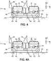
- Each platforms 4a, 4b may be formed for instance by a metal frame provided with rollers, for instance balls, or more preferably rolls 4f having axes of rotation parallel to direction Y ( Figure 4 ) or parallel to direction X ( Figure 4A ).
- the rolls 4a enable free rolling of the battery block 1 in direction X and free sliding of the battery block 1 in direction Y.
- the rollers 4f could be replaced by any sliding surface, for instance a metallic surface or a surfaces coated with an antifriction material, i.e. a low friction material such as Teflon (R) or similar.
- These sliding surfaces may form the entire surfaces of said platforms 4a, 4b which may be flat or may be provided with sliding pads similar to those of Figure 1B or sliding beads similar to those of Figure 1C or other reliefs.
- control unit 5 might be adapted to free the rotation of wheels 43 when the charged battery block 1 is lifted, to facilitate movement of the battery block 1 parallel to direction Y during fitting with the battery dock.
- the platforms 4a, 4b slightly overlap the base 12 of the external casing 10 of the battery block 1 (for instance of 1 mm on each side).
- the second platform 4b for the discharged battery block 1 is preferably equipped with a of funnel shaped guide 4e (having tapered sides), which allows for adjusting the position of the discharged battery block 1.
- the funnel shaped guide 4e has a sliding surface.
- the control unit 5 is part of the battery exchange station and provides communication with the battery lift 4, the battery dock 2 and the blocking device 3a. It processes the sensor signals and based on them controls horizontal movement of the battery lift 4 and vertical movement of the lift assemblies 4a', 4b' and mechanical locks 2a of the battery case. Communication of the control unit 5 with the trolley 4 and the ramp 3 may be direct (wired), while communication of the control unit 5 with the battery dock 2 is preferably wireless.
- the battery exchange system as described above operates as follows.
- the driver moves the vehicle forward until the front wheels W enter the blocking devices 3a and then stops the vehicle.
- the blocking devices 3a ensure a correct front-rear position of the electric vehicle V and thus of the discharged battery block 1 of the vehicle.
- the vehicle position is confirmed to the control unit 5 by a signal received from pressure sensor 3b.
- the control unit 5 then sends a signal to the battery lift 4 (more particilarly to one of the battery lifts of the battery exchange station 6) with a charged battery block 1 to move under the vehicle V, i.e. under opening 31.
- the lateral orientation of the battery lift 4 is provided by the position sensor 4c of the trolley 4 and / or the position sensor 1c of the discharged battery 1. Data from position sensors are sent to the control unit 5 and when the position sensors 4c and 1c are directly above each other the control unit 5 sends an order to the battery lift 4 to stop.
- the second lift assembly 4b' After stopping, based on instructions of the control unit 5, the second lift assembly 4b' extends vertically upward the second platform 4b and pushes the discharged battery 1 deeper upward into the battery dock 2 to activate the pressure sensor 2d. Based on a signal received from sensor 2d, the control unit 5 sends a signal to remove the locks 2a from the battery holes 1a, which releases the discharged battery block 1 from the battery case 2.
- control unit 5 gives an instruction to lower the second lift assembly 4b' to move down the second platform 4b with discharged battery block 1.
- control unit 5 When both down 4a, 4b are in the same low position, the control unit 5 has the battery lift 4 move parallel to direction Y by a constant predetermined distance so that the first platform 4a with the charged battery is directly beneath the battery dock 2.
- the control unit 5 then (for instance with a delay of e.g. 5 seconds) instructs a release of mechanical locks 2a back to its extended (locked) position.
- the charged battery block 1 is lifted on the first platform 4a (using the first lift assembly 4a') and pushed into the battery dock 2 to force the mechanical locks 2a to enter the holes 1a on the sides of the battery block 1. Inserting the charged battery blocjk 1 into the battery dock 2 is possible, even if the battery 1 is not perfectly aligned with the battery dock 2 (the tolerance can be for instance of +/- 10 cm). This can be achieved due to the battery block tapered shape and the sliding surfaces of the battery dock 2, the tappered sides of the battery block 1 and the bottom of the battery block 1 frely moving on the first platform 4a.
- the control unit 5 then sends a signal to lower the first lift assembly 4a' to its original low position.
- control unit 5 may give an instruction to release the front wheel locking mechanism 3a, or the vehicle simply rolls thereon.
- control unit 5 instructs the battery lift 4 to return to the charging storage, where the discharged battery block 1 is removed from the second platform 4b, and another charged battery block 1 is loaded on the first platform 4a.
- the battery block 1 has a shape of a flat block 1.1 having homing cones (conical studs) 1.2 placed on its upper side.
- Example of dimensions of the battery bloc may be: length 3000 mm, width 1100 mm and thickness 100 mm.
- the dimensions of the battery block 1 are adapted according to the size of the electric vehicle V.
- the battery block 1 may extend approximately from 500 mm behind the front axle of the vehicle V to approximately 600 mm behind the rear axle.
- the width of the battery is set for allowing locking mechanical locks 2a from the battery dock, on both sides of the battery block 1.
- the battery block may have four identical homing cones 1.2 placed on upper side of the battery block 1.1, two front cones and two rear cones. This number of homing cones 1.2 is favorable to obtain a proper guidance of the battery block in the horizontal plane when inserting the battery block into the battery dock of the vehicle.
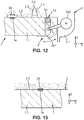
- each homing cone 1.2 is fitted inside a conical hole 2.3 of corresponding shape belonging to the top portion 2.2 of the battery dock 2 ( Figure 12 ).
- the homing cones 1.2 slide inside the conical holes 2.3 to ensure horizontal guidance of the battery block 1 toward its proper position relative to the battery dock 2.
- the front homing cones 1.2 may be placed in a proximity of the front edge of the chassis on each side of the central tunnel and the rear homing cones 1.2 may be placed under the rear seats of the vehicle.
- At least one pair of the homing cones 1.2 contains electric connector terminals 1b adapted to connect to complementary electrical connectors 2b formed in the corresponding conical holes 2.3.
- Homing cones 1.2 may also contain heating /cooling system connectors 1f for heating or cooling the battery block 1, adapted to connect with complementary heating /cooling system connectors (not shown) formed in the corresponding conical holes 2.3.
- the rear homing cones 1.2 contain electric connectors terminals 1b and the front homing cones 1.2 contain heating /cooling system connectors 1f.
- Homing cones 1.2 are preferably in a shape of truncated cones with a cylindrical lower part, where the conical upper part is used for self-positioning of the battery block 1 during inserting into the battery dock of the vehicle and the lower cylindrical part is used for bringing the already centered battery block 1 to contact with electrical connectors 2b of the vehicle.
- Preferable dimensions of the homing cones may be: height approximately 150 mm and diameter approximately 120 mm.
- a position sensor 1c may be located on the rear part of the battery block 1.1 between the two rear cones 1.2. It may be part of an optical sensor, e.g. in a form of a mirror or other reflection surface, while the battery dock 2 has a corresponding position sensor 2c ( Figure 12 ) having for instance a directive light emitter and a light detector to detect light reflected by the mirror 1c.
- a connection sensor 1e may be located on the upper part of the battery block 1.1. It is preferably a ferromagnetic counterpart of a magneto inductive sensor 2e located in the top portion 2.2 of the battery dock 2 ( Figure 13 ).
- the battery block 1 may be attached to the battery dock 2 by mechanical locks 2a.
- the mechanical locks 2a may be swinging locks extending on the sides 2.1 of the battery dock 2, formed for instance by a threshold of the car chassis.
- each mechanical lock 2a may include a latch 2a1 of L profile which is pivotally mounted in the battery dock 2 on a rotation axis X0 parallel to direction X.
- the latches are actuated by servomotors 2a2 placed for instance in the sides 2.1 of the battery dock 2, to rotate between an unlocked position (in dashed lines on Figure 12 ) where the locks 2a release the battery block 1 and a locked position (in plain lines) where the latches 2a1 are applied on the sides of the battery block and under the battery block to hold said battery block 1 in the battery dock 2.
- the battery dock 2 is formed on the vehicle chassis and has dimensions corresponding to the flat block 1.1 with a side tolerance of e.g. 40 mm during insertion of the battery block 1 in the battery dock 2.
- the first and second platforms 4a, 4b of the battery lift may be provided for instance with metal rollers 4f instead of silicone rollers.
- the metal rollers may be made for instance from steel with a zinc finish.
Landscapes
- Engineering & Computer Science (AREA)
- Transportation (AREA)
- Mechanical Engineering (AREA)
- Power Engineering (AREA)
- Life Sciences & Earth Sciences (AREA)
- Structural Engineering (AREA)
- Combustion & Propulsion (AREA)
- Chemical & Material Sciences (AREA)
- Sustainable Development (AREA)
- Sustainable Energy (AREA)
- Civil Engineering (AREA)
- Geology (AREA)
- Arrangement Or Mounting Of Propulsion Units For Vehicles (AREA)
- Vehicle Cleaning, Maintenance, Repair, Refitting, And Outriggers (AREA)
- Electric Propulsion And Braking For Vehicles (AREA)
Claims (13)
- Batterieaustauschsystem für ein batteriebetriebenes Elektrofahrzeug (V), umfassend:- einen austauschbaren Batterieblock (1);- eine Batteriestation (2), die an der Unterseite des Elektrofahrzeugs (V) definiert und nach unten offen ist, wobei die Batteriestation (2) dazu ausgelegt ist, den Batterieblock (1) zur elektrischen und mechanischen Verbindung durch vertikales Anbringen aufzunehmen, wenn eine solche Batterie von unterhalb des Elektrofahrzeugs (V) angehoben wird, wobei sich der Batterieblock (1) in Bezug auf das Elektrofahrzeug (V) in einer vorbestimmten Referenzposition, die in einer horizontalen Ebene definiert ist, befindet, wenn der Batterieblock (1) elektrisch und mechanisch mit der Batteriestation (2) verbunden ist;- einen Batterieheber (4) zum Anheben des Batterieblocks (1) unterhalb des Elektrofahrzeugs (V);wobei:- der Batterieblock (1) ein äußeres Gehäuse (10) aufweist, das eine Umfangswand (11) beinhaltet, und wobei die Umfangswand (11) einen pyramidenförmigen Teil (14, 15) aufweist, der zumindest einen abgeschrägt geformten männlichen Teil ausbildet;- wobei die Batteriestation ein inneres Gehäuse (20) aufweist, das eine innere Umfangswand (21) beinhaltet, und wobei die innere Umfangswand (20) einen pyramidenförmigen Innenteil (24, 25) aufweist, der zumindest einen abgeschrägt geformten weiblichen Teil ausbildet;- wobei der Batterieblock (1) und die Batteriestation (2) Führungen (14, 15, 24, 25) aufweisen, die dazu ausgelegt sind, miteinander zusammenzuwirken, um den Batterieblock (1) horizontal zur Referenzposition hin zu führen, wenn der Batterieblock (1) zum Anbringen an der Batteriestation (2) angehoben wird, wobei die Führungen den zumindest einen abgeschrägt geformten männlichen Teil (14, 15) und den zumindest einen abgeschrägt geformten weiblichen Teil (24, 25), der dazu ausgelegt ist, den abgeschrägt geformten männlichen Teil aufzunehmen, beinhalten;- wobei die Führungen (14, 15, 24, 25) Gleitflächen (14, 15, 24, 25; 14a, 15a; 14c, 15c) beinhalten, die dazu ausgelegt sind, frei aufeinander zu gleiten, um den Batterieblock (1) horizontal zur Referenzposition hin zu führen;und der Batterieheber (4) dazu ausgelegt ist, zuzulassen, dass sich der Batterieblock (1) in Bezug auf das Elektrofahrzeug (V) horizontal frei bewegen kann, wenn der Batterieblock (1) zum Anbringen an der Batteriestation (2) angehoben und horizontal zur Referenzposition hin geführt wird, wobei der Batterieheber eine Plattform (4a) zum Stützen des Batterieblocks und eine Hubanordnung (4a') zum Anheben und Absenken der Plattform beinhaltet,
dadurch gekennzeichnet, dass der Batterieblock auf der Plattform horizontal frei bewegbar ist, wobei der Batterieblock auf der Plattform horizontal gleiten kann oder rollend auf der Plattform aufliegt, um auf der Plattform frei bewegbar zu sein. - Batterieaustauschsystem nach Anspruch 1, wobei sich der Batterieblock (1) längs in einer ersten horizontalen Richtung (X) erstreckt und sich der zumindest eine abgeschrägt geformte männliche Teil (14, 15) zumindest in einer zweiten horizontalen Richtung (Y) im Wesentlichen senkrecht zur ersten horizontalen Richtung verjüngt.
- Batterieaustauschsystem nach einem der Ansprüche 1 - 2, wobei sich der Batterieblock (1) längs in einer ersten horizontalen Richtung (X) erstreckt und sich der zumindest eine abgeschrägt geformte weibliche Teil (24, 25) zumindest in einer zweiten horizontalen Richtung (Y) im Wesentlichen senkrecht zur ersten horizontalen Richtung verjüngt.
- Batterieaustauschsystem nach einem der vorangehenden Ansprüche, wobei die Gleitflächen (14, 15) der Führungen des Batterieblocks (1) Gleitkissen (14a, 15a) beinhalten.
- Batterieaustauschsystem nach einem der Ansprüche 1 - 3, wobei die Führungen jeweils zumindest eine Rolle (14d, 15d) und eine sich verjüngende Fläche (24, 25) beinhalten, auf der die Rolle rollen kann, um den Batterieblock (1) horizontal zur Referenzposition hin zu führen.
- Batterieaustauschsystem nach einem der vorangehenden Ansprüche, wobei der Batterieheber (4) dazu ausgelegt ist, in Bezug auf das Elektrofahrzeug (V) horizontal frei bewegbar zu sein, wenn der Batterieblock (1) zum Anbringen an der Batteriestation (2) angehoben und horizontal zur Referenzposition hin geführt wird.
- Batterieaustauschsystem nach Anspruch 1, wobei die Plattform (4a) Rollen (4f) aufweist.
- Batterieaustauschsystem nach Anspruch 7, wobei der Batterieblock (1) auf der Plattform (4a) in einer ersten Richtung (X) rollend aufliegt, wobei die Rollen (4f) sich in einer zweiten Richtung (Y) im Wesentlichen senkrecht zur ersten Richtung (X) erstrecken und ein freies Gleiten des Batterieblocks in der zweiten Richtung (Y) ermöglichen.
- Batterieaustauschsystem nach einem der vorangehenden Ansprüche, ferner beinhaltend eine Batterieaustauschstation (6) mit:- einer Fahrzeugspur (3), auf der sich das Elektrofahrzeug in einer ersten horizontalen Richtung (X) fortbewegen kann;- einer Hubspur (40), entlang derer sich der Batterieheber (4) in einer zweiten Richtung (Y) im Wesentlichen senkrecht zur ersten Richtung (X) bewegen kann, wobei die Hubspur unter der Fahrzeugspur (3) ist,wobei die Fahrzeugspur eine Öffnung (31) aufweist, die dazu ausgelegt ist, dem Batterieblock (1) freien Durchgang bereitzustellen, wenn der Batterieblock (1) zum Anbringen in der Batteriestation (2) angehoben wird, wobei die Öffnung (31) der Hubspur (40) entspricht.
- Batterieaustauschsystem nach Anspruch 9, wobei die Fahrzeugspur zumindest eine Radblockiervorrichtung (3a) beinhaltet, die dazu ausgelegt ist, das Elektrofahrzeug (V) in einer vorbestimmten Position, die für einen Batterieaustausch geeignet ist, zu blockieren.
- Batterieaustauschsystem nach Anspruch 10, ferner beinhaltend einen Einstellmechanismus (33, 34) zum Einstellen einer Position der Blockiervorrichtung (3a) in einer zur Fahrzeugspur (3) parallelen Richtung (X).
- Batterieaustauschsystem nach einem der vorangehenden Ansprüche, wobei der Batterieheber (4) horizontal in Bezug auf das Fahrzeug bewegbar ist und das Batterieaustauschsystem ferner Folgendes beinhaltet:- zumindest einen Positionssensor (4c), der dazu ausgelegt ist, zu erkennen, ob der Batterieblock (1) in Bezug auf die Batteriestation (2) richtig positioniert ist, um den Batterieblock (1) zur Batteriestation (2) anzuheben,- ein Steuersystem, das dazu ausgelegt ist, den Batterieheber (4) in Bezug auf das Fahrzeug gemäß Informationen, die vom Positionssensor empfangen wurden, zu bewegen.
- Batterieaustauschsystem nach einem der vorangehenden Ansprüche, wobei der Batterieheber (4) Folgendes beinhaltet:- eine erste Plattform (4a) zum Stützen eines aufgeladenen Batterieblocks (1),- eine erste Hubanordnung (4a') zum Anheben und Absenken der ersten Plattform (4a),- eine zweite Plattform (4b) zum Stützen eines entladenen Batterieblocks (1),- eine zweite Hubanordnung (4b') zum Anheben und Absenken der zweiten Plattform (4b).
Applications Claiming Priority (2)
| Application Number | Priority Date | Filing Date | Title |
|---|---|---|---|
| US201562173716P | 2015-06-10 | 2015-06-10 | |
| PCT/EP2016/063221 WO2016198552A1 (en) | 2015-06-10 | 2016-06-09 | Battery exchange system |
Publications (2)
| Publication Number | Publication Date |
|---|---|
| EP3307585A1 EP3307585A1 (de) | 2018-04-18 |
| EP3307585B1 true EP3307585B1 (de) | 2019-12-18 |
Family
ID=56121075
Family Applications (1)
| Application Number | Title | Priority Date | Filing Date |
|---|---|---|---|
| EP16728932.1A Active EP3307585B1 (de) | 2015-06-10 | 2016-06-09 | Batterieaustauschsystem |
Country Status (6)
| Country | Link |
|---|---|
| US (1) | US20180154789A1 (de) |
| EP (1) | EP3307585B1 (de) |
| JP (1) | JP6568313B2 (de) |
| KR (1) | KR20180025889A (de) |
| CN (1) | CN107848431A (de) |
| WO (1) | WO2016198552A1 (de) |
Cited By (4)
| Publication number | Priority date | Publication date | Assignee | Title |
|---|---|---|---|---|
| US20210031915A1 (en) * | 2018-03-28 | 2021-02-04 | Sony Corporation | Unmanned aerial vehicle |
| IT202000031886A1 (it) | 2020-12-22 | 2022-06-22 | Hype S R L | Pacco batterie ricaricabile articolato |
| IT202100004673A1 (it) | 2021-03-01 | 2022-09-01 | Hype S R L | Pacco batterie ricaricabile estraibile |
| DE102022004646A1 (de) | 2022-12-12 | 2023-12-28 | Mercedes-Benz Group AG | Batteriewechselsystem für ein elektrisches Fahrzeug |
Families Citing this family (60)
| Publication number | Priority date | Publication date | Assignee | Title |
|---|---|---|---|---|
| BR112017022791A2 (pt) * | 2015-04-22 | 2018-07-17 | Ahrens Jason | sistema para a troca de alimentação de veículo, sistema de veículo de bordo de veículo e método para a troca de alimentação de veículo |
| JP6724343B2 (ja) * | 2015-11-17 | 2020-07-15 | オムロン株式会社 | 予約管理装置、予約管理システムおよび予約管理方法 |
| JP6766343B2 (ja) | 2015-11-17 | 2020-10-14 | オムロン株式会社 | バッテリ予約装置 |
| JP6597218B2 (ja) * | 2015-11-17 | 2019-10-30 | オムロン株式会社 | バッテリ予約装置およびバッテリ予約方法 |
| JP6582909B2 (ja) * | 2015-11-17 | 2019-10-02 | オムロン株式会社 | バッテリ予約装置およびバッテリ予約方法 |
| US20170282734A1 (en) * | 2016-04-04 | 2017-10-05 | Skycatch, Inc. | Unmanned aerial vehicle self-aligning battery assembly |
| US10807492B1 (en) * | 2016-04-15 | 2020-10-20 | X Development Llc | Switchable magnetic battery docking |
| JP7066743B2 (ja) | 2016-12-30 | 2022-05-13 | 上海電巴新能源科技有限公司 | バッテリー交換移動作業台及びスピード交換システム |
| WO2019104884A1 (zh) * | 2017-11-30 | 2019-06-06 | 上海电巴新能源科技有限公司 | 换电小车、换电控制系统及其控制方法 |
| CN108688625A (zh) * | 2017-04-01 | 2018-10-23 | 上海电巴新能源科技有限公司 | 电池装取控制系统、电动汽车换电控制系统及其方法 |
| CN207028817U (zh) * | 2017-04-10 | 2018-02-23 | 上海蔚来汽车有限公司 | 储能单元的可调节安装组件 |
| EP3663142A4 (de) * | 2017-08-02 | 2021-04-28 | Shanghai Dianba New Energy Technology Co., Ltd. | Batteriekasten, konsole und batteriekastenanordnung |
| CN207809025U (zh) * | 2017-11-08 | 2018-09-04 | 蔚来汽车有限公司 | 用于电池包的安装结构、电池包以及汽车 |
| DE102017011016A1 (de) * | 2017-11-28 | 2019-06-27 | Jan Völker | Batteriewechselstation für Elektrofahrzeuge mit standardisierten Batterien und Batterieaufnahmesysteme in den Elektrofahrzeugen |
| CN113212233B (zh) * | 2017-11-30 | 2022-08-30 | 上海电巴新能源科技有限公司 | 穿梭式电池包更换设备及包含其的换电站 |
| CN109895750A (zh) | 2017-12-08 | 2019-06-18 | 上海电巴新能源科技有限公司 | 换电系统 |
| US10906383B2 (en) * | 2018-02-28 | 2021-02-02 | Artisan Vehicle Systems, Inc. | Alignment and locking mechanism for removeable battery assembly |
| CN108382371A (zh) * | 2018-03-23 | 2018-08-10 | 江西丹巴赫机器人股份有限公司 | 新能源汽车电池快换机器人系统 |
| CN108382372A (zh) * | 2018-04-09 | 2018-08-10 | 广东技术师范学院 | 一种电动车快速换电系统 |
| NL2020843B1 (en) * | 2018-04-30 | 2019-11-07 | R U Eng & Detachering B V | Battery exchange system and method |
| IT201800007238A1 (it) * | 2018-07-17 | 2020-01-17 | Metodo per la sostituzione rapida di batterie per motori elettrici | |
| CN110745108B (zh) * | 2018-07-20 | 2022-03-22 | 奥动新能源汽车科技有限公司 | 换电控制系统及方法 |
| CN110816489B (zh) * | 2018-07-23 | 2023-05-23 | 奥动新能源汽车科技有限公司 | 换电系统 |
| CN110887437B (zh) * | 2018-09-10 | 2021-10-29 | 奥动新能源汽车科技有限公司 | 电池仓的定位方法及定位系统 |
| CN109367437B (zh) * | 2018-10-10 | 2020-06-05 | 杭州六创电动汽车科技有限公司 | 一种电动汽车的电池更换方法 |
| CN109291893A (zh) * | 2018-10-10 | 2019-02-01 | 王德恒 | 一种移动的电动车电池组智能更换系统 |
| US10476061B1 (en) * | 2018-12-31 | 2019-11-12 | Chongqing Jinkang New Energy Vehicle Co., Ltd. | Electric vehicle cabin floor structure |
| WO2020161973A1 (ja) * | 2019-02-05 | 2020-08-13 | 本田技研工業株式会社 | 電動車両及びバッテリユニット |
| EP3694014A1 (de) * | 2019-02-06 | 2020-08-12 | Battswap, Inc. | Batterieblock mit beweglicher anordnung |
| CN111605392B (zh) * | 2019-02-25 | 2024-01-30 | 浙江吉智新能源汽车科技有限公司 | 一种电池更换装置及汽车 |
| EP3946995B1 (de) * | 2019-04-04 | 2023-02-15 | Volvo Truck Corporation | System und verfahren zur installation von traktionsbatterien für ein fahrzeug |
| CN112026577B (zh) * | 2019-06-03 | 2022-03-08 | 浙江吉智新能源汽车科技有限公司 | 一种换电装置及车辆 |
| US11254224B2 (en) | 2019-06-07 | 2022-02-22 | Artisan Vehicle Systems, Inc. | Battery load mechanism for electric LHD mining machine |
| US11208308B1 (en) * | 2019-08-07 | 2021-12-28 | Chase Pearce | Load stabilization device |
| CN110667526A (zh) * | 2019-10-08 | 2020-01-10 | 北京京东乾石科技有限公司 | Agv换电自动充电装置、系统及方法 |
| CN110667362A (zh) * | 2019-10-12 | 2020-01-10 | 邳州陆压汽车配件有限公司 | 一种新能源汽车快速更换式电池组支架 |
| CN110979510B (zh) * | 2019-12-20 | 2020-11-27 | 池州海琳服装有限公司 | 一种新能源电动汽车用的锂电池安装辅助装置 |
| CN111204254A (zh) * | 2020-01-20 | 2020-05-29 | 浙江吉智新能源汽车科技有限公司 | 一种电池包锁紧机构、电池包解锁机构、电池包及车辆 |
| CN114801863A (zh) * | 2020-01-23 | 2022-07-29 | 奥动新能源汽车科技有限公司 | 夹车道控制方法及系统、电子设备及存储介质 |
| DE102020107191A1 (de) | 2020-03-16 | 2021-09-16 | Volkswagen Aktiengesellschaft | Elektrofahrzeug, Batteriesystem, Montagevorrichtung und Verfahren zum Wechseln einer Antriebsbatterie in einem Elektrofahrzeug |
| CN111452663B (zh) * | 2020-05-06 | 2021-08-13 | 宁波曼汶智能装备有限公司 | 一种地下式新能源汽车电池更换机器人 |
| CN111532172A (zh) * | 2020-05-14 | 2020-08-14 | 瑞安市驰恒传动设备有限公司 | 一种用于电动乘车用底盘换电定位装置 |
| WO2021238938A1 (zh) * | 2020-05-25 | 2021-12-02 | 奥动新能源汽车科技有限公司 | 换电站及其换电方法 |
| US11964584B2 (en) | 2020-09-16 | 2024-04-23 | Apple Inc. | Accessory power pack |
| CN114475340A (zh) * | 2020-10-26 | 2022-05-13 | 奥动新能源汽车科技有限公司 | 换电控制方法、系统、电子设备及计算机可读存储介质 |
| KR20220062177A (ko) * | 2020-11-06 | 2022-05-16 | 현대자동차주식회사 | 모빌리티 배터리 교체시스템 |
| CN112477681B (zh) * | 2020-11-30 | 2022-05-10 | 浙江吉利控股集团有限公司 | 一种车辆换电控制方法、装置、设备及存储介质 |
| CN112477685B (zh) * | 2020-12-14 | 2023-01-13 | 泽清新能源科技有限公司 | 一种换电系统 |
| CN112721719A (zh) * | 2020-12-24 | 2021-04-30 | 余国桢 | 电池更换充电系统 |
| DE102021202381A1 (de) | 2021-03-11 | 2022-09-15 | Volkswagen Aktiengesellschaft | Vorrichtung, Verfahren und System zum Sichern eines wiederaufladbaren Speichermoduls für elektrische Energie |
| WO2022221111A1 (en) * | 2021-04-16 | 2022-10-20 | Lixiong Wu | Apparatus and method for electric vehicle battery resource sharing |
| CN112977152B (zh) * | 2021-04-20 | 2021-07-30 | 禾美(浙江)汽车股份有限公司 | 一种电动汽车底盘充换电站及更换电池的方法 |
| KR20220159548A (ko) | 2021-05-25 | 2022-12-05 | 최영철 | 배터리 리프팅 장치 |
| CN113370836A (zh) * | 2021-07-20 | 2021-09-10 | 重庆峘能电动车科技有限公司 | Agv机器人及换电站 |
| CN113415207B (zh) * | 2021-08-09 | 2024-05-03 | 安徽华菱汽车有限公司 | 一种纯电动重卡换电系统液压锁止机构 |
| CN113781565B (zh) * | 2021-09-15 | 2023-05-23 | 湖南视比特机器人有限公司 | 一种电池更换方法、系统、电子设备及存储介质 |
| WO2023041083A1 (zh) * | 2021-09-17 | 2023-03-23 | 奥动新能源汽车科技有限公司 | 位置确定装置、载车平台及换电站 |
| CN113859043B (zh) * | 2021-11-04 | 2023-08-11 | 姜珠 | 一种新能源汽车换电站 |
| JP7441901B2 (ja) | 2022-08-02 | 2024-03-01 | 株式会社エスシー・マシーナリ | 電動式作業車両 |
| CN115320450B (zh) * | 2022-09-02 | 2023-04-07 | 上海理工大学 | 一种用于纯电动汽车快速更换电池的往复摆动连接装置 |
Citations (6)
| Publication number | Priority date | Publication date | Assignee | Title |
|---|---|---|---|---|
| DE102008056895A1 (de) * | 2008-05-23 | 2009-11-26 | Jungheinrich Ag | Batterieblock-Wechseladapter und Batteriewechselsystem |
| WO2010070642A1 (en) * | 2008-12-15 | 2010-06-24 | Guy German | Mobile battery replacement unit |
| JP2011168127A (ja) * | 2010-02-17 | 2011-09-01 | Ihi Corp | 蓄電装置交換システム |
| DE102011108199A1 (de) * | 2011-07-20 | 2012-01-26 | Daimler Ag | Elektroantriebsvorrichtung eines Kraftfahrzeugs, mit einem Akkumulatorfach |
| US20120097489A1 (en) * | 2009-04-20 | 2012-04-26 | Renault Sas | Device for moving and attaching a component between two positions |
| US20120111654A1 (en) * | 2009-06-16 | 2012-05-10 | Renault Sas | Secure arrangement for a battery in a motor vehicle |
Family Cites Families (24)
| Publication number | Priority date | Publication date | Assignee | Title |
|---|---|---|---|---|
| US5612606A (en) * | 1994-09-15 | 1997-03-18 | David C. Guimarin | Battery exchange system for electric vehicles |
| JPH09284901A (ja) * | 1996-04-18 | 1997-10-31 | Toyota Motor Corp | バッテリ保持装置 |
| US5998963A (en) * | 1998-06-11 | 1999-12-07 | Aarseth; Einar | Electric vehicle service center and method for exchanging and charging vehicle batteries |
| US7602143B2 (en) * | 2005-11-04 | 2009-10-13 | Peter David Capizzo | System for replenishing energy sources onboard different types of automotive vehicles |
| JP2008030722A (ja) * | 2006-08-01 | 2008-02-14 | Toyota Motor Corp | 車両機器の搭載構造 |
| JP2008260382A (ja) * | 2007-04-11 | 2008-10-30 | Toyota Motor Corp | 車両 |
| JP2011031813A (ja) * | 2009-08-04 | 2011-02-17 | Nissan Motor Co Ltd | 車両位置決め装置 |
| JP5136539B2 (ja) * | 2009-11-06 | 2013-02-06 | 株式会社豊田自動織機 | 電気自動車のバッテリ搭載構造 |
| CN101870284B (zh) * | 2010-06-18 | 2012-11-28 | 崔丽娜 | 电动汽车的电池自动更换系统以及自动更换电动汽车电池的方法 |
| SE536036C2 (sv) * | 2010-06-21 | 2013-04-09 | Sten Corfitsen | Förfarande för att byta batteri i batteridrivna fordon. |
| JP2012006498A (ja) * | 2010-06-25 | 2012-01-12 | Hirata Corp | バッテリ交換システムおよびバッテリ交換方法 |
| FR2964609B1 (fr) * | 2010-09-14 | 2012-09-28 | Renault Sa | Structure de vehicule automobile a batterie d'accumulateurs amovible |
| CN102390794A (zh) * | 2011-01-24 | 2012-03-28 | 朗瑞迪尔(天津)新能源科技有限公司 | 电动汽车电池组的便携更换车 |
| JP5273187B2 (ja) * | 2011-03-15 | 2013-08-28 | 株式会社豊田自動織機 | 車両のバッテリ交換装置 |
| JP5141795B2 (ja) * | 2011-06-20 | 2013-02-13 | 株式会社豊田自動織機 | 車両用バッテリユニット装着装置 |
| JP2013139207A (ja) * | 2012-01-04 | 2013-07-18 | Toyota Industries Corp | 端子カバー転移構造 |
| DE102012012739B4 (de) * | 2012-06-26 | 2014-11-27 | Günther Büdenbender | Vorrichtungen und Verfahren zum teilautomatisierten, automatisierten und mobilen Wechsel einer Elektro-Batterie für den Antrieb von Automobilen |
| JP2014013661A (ja) * | 2012-07-03 | 2014-01-23 | Nissan Motor Co Ltd | 車両用バッテリパックの製造方法 |
| DE102012218809A1 (de) * | 2012-10-16 | 2013-01-31 | Schaeffler Technologies AG & Co. KG | Elektrofahrzeug mit wechselbarer Traktionsbatterie |
| US8973254B2 (en) * | 2013-03-07 | 2015-03-10 | Jasper Ev Tech, Llc | System and method for rapid battery exchange in electric vehicles |
| US9511459B2 (en) * | 2013-07-02 | 2016-12-06 | Denis Ernest Celestin BUFFET | Automatic system for quick dropping of the battery, integrated to an electrical or hybrid vehicle, and consequences on its maximum loading weight |
| CN104590086A (zh) * | 2013-10-09 | 2015-05-06 | 黄金富知识产权咨询(深圳)有限公司 | 一种供电动车补给能源的流动能源补给车 |
| CN104590218A (zh) * | 2013-10-09 | 2015-05-06 | 黄金富知识产权咨询(深圳)有限公司 | 一种电动车能源补给系统 |
| CN104118404B (zh) * | 2014-06-30 | 2016-07-06 | 王俊 | 更换电池机器人 |
-
2016
- 2016-06-09 EP EP16728932.1A patent/EP3307585B1/de active Active
- 2016-06-09 WO PCT/EP2016/063221 patent/WO2016198552A1/en active Application Filing
- 2016-06-09 US US15/735,027 patent/US20180154789A1/en not_active Abandoned
- 2016-06-09 CN CN201680040298.6A patent/CN107848431A/zh active Pending
- 2016-06-09 JP JP2018516627A patent/JP6568313B2/ja active Active
- 2016-06-09 KR KR1020187000481A patent/KR20180025889A/ko unknown
Patent Citations (6)
| Publication number | Priority date | Publication date | Assignee | Title |
|---|---|---|---|---|
| DE102008056895A1 (de) * | 2008-05-23 | 2009-11-26 | Jungheinrich Ag | Batterieblock-Wechseladapter und Batteriewechselsystem |
| WO2010070642A1 (en) * | 2008-12-15 | 2010-06-24 | Guy German | Mobile battery replacement unit |
| US20120097489A1 (en) * | 2009-04-20 | 2012-04-26 | Renault Sas | Device for moving and attaching a component between two positions |
| US20120111654A1 (en) * | 2009-06-16 | 2012-05-10 | Renault Sas | Secure arrangement for a battery in a motor vehicle |
| JP2011168127A (ja) * | 2010-02-17 | 2011-09-01 | Ihi Corp | 蓄電装置交換システム |
| DE102011108199A1 (de) * | 2011-07-20 | 2012-01-26 | Daimler Ag | Elektroantriebsvorrichtung eines Kraftfahrzeugs, mit einem Akkumulatorfach |
Cited By (5)
| Publication number | Priority date | Publication date | Assignee | Title |
|---|---|---|---|---|
| US20210031915A1 (en) * | 2018-03-28 | 2021-02-04 | Sony Corporation | Unmanned aerial vehicle |
| IT202000031886A1 (it) | 2020-12-22 | 2022-06-22 | Hype S R L | Pacco batterie ricaricabile articolato |
| IT202100004673A1 (it) | 2021-03-01 | 2022-09-01 | Hype S R L | Pacco batterie ricaricabile estraibile |
| EP4053971A1 (de) | 2021-03-01 | 2022-09-07 | Hype S.r.l. | Removable und rechargeable battery pack |
| DE102022004646A1 (de) | 2022-12-12 | 2023-12-28 | Mercedes-Benz Group AG | Batteriewechselsystem für ein elektrisches Fahrzeug |
Also Published As
| Publication number | Publication date |
|---|---|
| KR20180025889A (ko) | 2018-03-09 |
| WO2016198552A1 (en) | 2016-12-15 |
| JP6568313B2 (ja) | 2019-08-28 |
| JP2018518421A (ja) | 2018-07-12 |
| US20180154789A1 (en) | 2018-06-07 |
| EP3307585A1 (de) | 2018-04-18 |
| CN107848431A (zh) | 2018-03-27 |
Similar Documents
| Publication | Publication Date | Title |
|---|---|---|
| EP3307585B1 (de) | Batterieaustauschsystem | |
| US9637093B2 (en) | System and method for rapid battery exchange in electric vehicles | |
| US9770993B2 (en) | Electric vehicle charging station | |
| US20110106294A1 (en) | Automatic battery exchange system for mobile vehicles | |
| US20180001777A1 (en) | Charging station and method for automatically charging an electrical energy storage means in a vehicle | |
| US20140369798A1 (en) | Semi-automatic station for exchanging a traction battery of an electric or hybrid vehicle | |
| US20170349055A1 (en) | Apparatus and method for electrically connecting a charging station to a charging socket of a vehicle | |
| CN109797995B (zh) | 用于自动化运输车辆的运输系统 | |
| US20210023955A1 (en) | Parking vehicle, method for parking an electric vehicle and for charging the battery of the electric vehicle, and parking space system | |
| DE102010027670B4 (de) | Vorrichtung und Verfahren zum Anschließen eines elektrischen Energiespeichers an eine Ladestation | |
| EP3347229B1 (de) | Verfahren und vorrichtung zum laden eines elektrischen fahrzeugs | |
| WO2013158026A1 (en) | Device, battery storage device and method for replacing batteries in battery powered vehicles | |
| CN214112307U (zh) | 换电站 | |
| US11021138B2 (en) | Parking robot for a motor vehicle and a method for operating such a parking robot | |
| CN110001599A (zh) | 换电平台、换电机器人及充换电站 | |
| KR20140047686A (ko) | 차량의 위치 선정 및 차량 전력 공급 배터리 교환 | |
| US20220212638A1 (en) | Systems and Methods for Automated In-Situ Swapping of Batteries for Electric Vehicles | |
| WO2022064230A1 (en) | System and method for electrical vehicles battery swapping | |
| CN114126991B (zh) | 用于物体在表面上的运输的运输装置 | |
| US11485246B1 (en) | Individualized vehicular charging mat | |
| US11151823B2 (en) | Motor vehicle and locker item transferring method and item transferring system | |
| CN114988044B (zh) | 基于运输系统的自动定位方法 | |
| US20230278455A1 (en) | Battery exchange station for electric vehicle system and methods | |
| US20230278456A1 (en) | Electric vehicle alignment system and method | |
| US20230278411A1 (en) | Electric vehicle battery attachment system and method |
Legal Events
| Date | Code | Title | Description |
|---|---|---|---|
| STAA | Information on the status of an ep patent application or granted ep patent |
Free format text: STATUS: THE INTERNATIONAL PUBLICATION HAS BEEN MADE |
|
| PUAI | Public reference made under article 153(3) epc to a published international application that has entered the european phase |
Free format text: ORIGINAL CODE: 0009012 |
|
| STAA | Information on the status of an ep patent application or granted ep patent |
Free format text: STATUS: REQUEST FOR EXAMINATION WAS MADE |
|
| 17P | Request for examination filed |
Effective date: 20170830 |
|
| AK | Designated contracting states |
Kind code of ref document: A1 Designated state(s): AL AT BE BG CH CY CZ DE DK EE ES FI FR GB GR HR HU IE IS IT LI LT LU LV MC MK MT NL NO PL PT RO RS SE SI SK SM TR |
|
| AX | Request for extension of the european patent |
Extension state: BA ME |
|
| DAV | Request for validation of the european patent (deleted) | ||
| DAX | Request for extension of the european patent (deleted) | ||
| STAA | Information on the status of an ep patent application or granted ep patent |
Free format text: STATUS: EXAMINATION IS IN PROGRESS |
|
| 17Q | First examination report despatched |
Effective date: 20181004 |
|
| REG | Reference to a national code |
Ref country code: DE Ref legal event code: R079 Ref document number: 602016026396 Country of ref document: DE Free format text: PREVIOUS MAIN CLASS: B60L0011180000 Ipc: B60L0053800000 |
|
| GRAP | Despatch of communication of intention to grant a patent |
Free format text: ORIGINAL CODE: EPIDOSNIGR1 |
|
| STAA | Information on the status of an ep patent application or granted ep patent |
Free format text: STATUS: GRANT OF PATENT IS INTENDED |
|
| RIC1 | Information provided on ipc code assigned before grant |
Ipc: B60K 1/04 20190101ALI20190312BHEP Ipc: B66F 9/06 20060101ALI20190312BHEP Ipc: B60L 50/64 20190101ALI20190312BHEP Ipc: B60L 53/80 20190101AFI20190312BHEP Ipc: B60S 5/06 20190101ALI20190312BHEP |
|
| INTG | Intention to grant announced |
Effective date: 20190401 |
|
| GRAS | Grant fee paid |
Free format text: ORIGINAL CODE: EPIDOSNIGR3 |
|
| GRAJ | Information related to disapproval of communication of intention to grant by the applicant or resumption of examination proceedings by the epo deleted |
Free format text: ORIGINAL CODE: EPIDOSDIGR1 |
|
| GRAL | Information related to payment of fee for publishing/printing deleted |
Free format text: ORIGINAL CODE: EPIDOSDIGR3 |
|
| STAA | Information on the status of an ep patent application or granted ep patent |
Free format text: STATUS: EXAMINATION IS IN PROGRESS |
|
| INTC | Intention to grant announced (deleted) | ||
| GRAJ | Information related to disapproval of communication of intention to grant by the applicant or resumption of examination proceedings by the epo deleted |
Free format text: ORIGINAL CODE: EPIDOSDIGR1 |
|
| GRAP | Despatch of communication of intention to grant a patent |
Free format text: ORIGINAL CODE: EPIDOSNIGR1 |
|
| GRAR | Information related to intention to grant a patent recorded |
Free format text: ORIGINAL CODE: EPIDOSNIGR71 |
|
| STAA | Information on the status of an ep patent application or granted ep patent |
Free format text: STATUS: GRANT OF PATENT IS INTENDED |
|
| GRAA | (expected) grant |
Free format text: ORIGINAL CODE: 0009210 |
|
| STAA | Information on the status of an ep patent application or granted ep patent |
Free format text: STATUS: THE PATENT HAS BEEN GRANTED |
|
| INTG | Intention to grant announced |
Effective date: 20191106 |
|
| AK | Designated contracting states |
Kind code of ref document: B1 Designated state(s): AL AT BE BG CH CY CZ DE DK EE ES FI FR GB GR HR HU IE IS IT LI LT LU LV MC MK MT NL NO PL PT RO RS SE SI SK SM TR |
|
| REG | Reference to a national code |
Ref country code: CH Ref legal event code: EP |
|
| REG | Reference to a national code |
Ref country code: IE Ref legal event code: FG4D |
|
| REG | Reference to a national code |
Ref country code: DE Ref legal event code: R096 Ref document number: 602016026396 Country of ref document: DE |
|
| REG | Reference to a national code |
Ref country code: AT Ref legal event code: REF Ref document number: 1214219 Country of ref document: AT Kind code of ref document: T Effective date: 20200115 |
|
| REG | Reference to a national code |
Ref country code: NL Ref legal event code: MP Effective date: 20191218 |
|
| PG25 | Lapsed in a contracting state [announced via postgrant information from national office to epo] |
Ref country code: BG Free format text: LAPSE BECAUSE OF FAILURE TO SUBMIT A TRANSLATION OF THE DESCRIPTION OR TO PAY THE FEE WITHIN THE PRESCRIBED TIME-LIMIT Effective date: 20200318 Ref country code: GR Free format text: LAPSE BECAUSE OF FAILURE TO SUBMIT A TRANSLATION OF THE DESCRIPTION OR TO PAY THE FEE WITHIN THE PRESCRIBED TIME-LIMIT Effective date: 20200319 Ref country code: FI Free format text: LAPSE BECAUSE OF FAILURE TO SUBMIT A TRANSLATION OF THE DESCRIPTION OR TO PAY THE FEE WITHIN THE PRESCRIBED TIME-LIMIT Effective date: 20191218 Ref country code: LT Free format text: LAPSE BECAUSE OF FAILURE TO SUBMIT A TRANSLATION OF THE DESCRIPTION OR TO PAY THE FEE WITHIN THE PRESCRIBED TIME-LIMIT Effective date: 20191218 Ref country code: SE Free format text: LAPSE BECAUSE OF FAILURE TO SUBMIT A TRANSLATION OF THE DESCRIPTION OR TO PAY THE FEE WITHIN THE PRESCRIBED TIME-LIMIT Effective date: 20191218 Ref country code: LV Free format text: LAPSE BECAUSE OF FAILURE TO SUBMIT A TRANSLATION OF THE DESCRIPTION OR TO PAY THE FEE WITHIN THE PRESCRIBED TIME-LIMIT Effective date: 20191218 Ref country code: NO Free format text: LAPSE BECAUSE OF FAILURE TO SUBMIT A TRANSLATION OF THE DESCRIPTION OR TO PAY THE FEE WITHIN THE PRESCRIBED TIME-LIMIT Effective date: 20200318 |
|
| REG | Reference to a national code |
Ref country code: LT Ref legal event code: MG4D |
|
| PG25 | Lapsed in a contracting state [announced via postgrant information from national office to epo] |
Ref country code: RS Free format text: LAPSE BECAUSE OF FAILURE TO SUBMIT A TRANSLATION OF THE DESCRIPTION OR TO PAY THE FEE WITHIN THE PRESCRIBED TIME-LIMIT Effective date: 20191218 Ref country code: HR Free format text: LAPSE BECAUSE OF FAILURE TO SUBMIT A TRANSLATION OF THE DESCRIPTION OR TO PAY THE FEE WITHIN THE PRESCRIBED TIME-LIMIT Effective date: 20191218 |
|
| PG25 | Lapsed in a contracting state [announced via postgrant information from national office to epo] |
Ref country code: AL Free format text: LAPSE BECAUSE OF FAILURE TO SUBMIT A TRANSLATION OF THE DESCRIPTION OR TO PAY THE FEE WITHIN THE PRESCRIBED TIME-LIMIT Effective date: 20191218 |
|
| PG25 | Lapsed in a contracting state [announced via postgrant information from national office to epo] |
Ref country code: RO Free format text: LAPSE BECAUSE OF FAILURE TO SUBMIT A TRANSLATION OF THE DESCRIPTION OR TO PAY THE FEE WITHIN THE PRESCRIBED TIME-LIMIT Effective date: 20191218 Ref country code: CZ Free format text: LAPSE BECAUSE OF FAILURE TO SUBMIT A TRANSLATION OF THE DESCRIPTION OR TO PAY THE FEE WITHIN THE PRESCRIBED TIME-LIMIT Effective date: 20191218 Ref country code: NL Free format text: LAPSE BECAUSE OF FAILURE TO SUBMIT A TRANSLATION OF THE DESCRIPTION OR TO PAY THE FEE WITHIN THE PRESCRIBED TIME-LIMIT Effective date: 20191218 Ref country code: PT Free format text: LAPSE BECAUSE OF FAILURE TO SUBMIT A TRANSLATION OF THE DESCRIPTION OR TO PAY THE FEE WITHIN THE PRESCRIBED TIME-LIMIT Effective date: 20200513 Ref country code: EE Free format text: LAPSE BECAUSE OF FAILURE TO SUBMIT A TRANSLATION OF THE DESCRIPTION OR TO PAY THE FEE WITHIN THE PRESCRIBED TIME-LIMIT Effective date: 20191218 |
|
| PG25 | Lapsed in a contracting state [announced via postgrant information from national office to epo] |
Ref country code: SK Free format text: LAPSE BECAUSE OF FAILURE TO SUBMIT A TRANSLATION OF THE DESCRIPTION OR TO PAY THE FEE WITHIN THE PRESCRIBED TIME-LIMIT Effective date: 20191218 Ref country code: IS Free format text: LAPSE BECAUSE OF FAILURE TO SUBMIT A TRANSLATION OF THE DESCRIPTION OR TO PAY THE FEE WITHIN THE PRESCRIBED TIME-LIMIT Effective date: 20200418 Ref country code: SM Free format text: LAPSE BECAUSE OF FAILURE TO SUBMIT A TRANSLATION OF THE DESCRIPTION OR TO PAY THE FEE WITHIN THE PRESCRIBED TIME-LIMIT Effective date: 20191218 |
|
| REG | Reference to a national code |
Ref country code: DE Ref legal event code: R097 Ref document number: 602016026396 Country of ref document: DE |
|
| REG | Reference to a national code |
Ref country code: AT Ref legal event code: MK05 Ref document number: 1214219 Country of ref document: AT Kind code of ref document: T Effective date: 20191218 |
|
| PLBE | No opposition filed within time limit |
Free format text: ORIGINAL CODE: 0009261 |
|
| STAA | Information on the status of an ep patent application or granted ep patent |
Free format text: STATUS: NO OPPOSITION FILED WITHIN TIME LIMIT |
|
| PG25 | Lapsed in a contracting state [announced via postgrant information from national office to epo] |
Ref country code: ES Free format text: LAPSE BECAUSE OF FAILURE TO SUBMIT A TRANSLATION OF THE DESCRIPTION OR TO PAY THE FEE WITHIN THE PRESCRIBED TIME-LIMIT Effective date: 20191218 Ref country code: DK Free format text: LAPSE BECAUSE OF FAILURE TO SUBMIT A TRANSLATION OF THE DESCRIPTION OR TO PAY THE FEE WITHIN THE PRESCRIBED TIME-LIMIT Effective date: 20191218 |
|
| 26N | No opposition filed |
Effective date: 20200921 |
|
| PG25 | Lapsed in a contracting state [announced via postgrant information from national office to epo] |
Ref country code: SI Free format text: LAPSE BECAUSE OF FAILURE TO SUBMIT A TRANSLATION OF THE DESCRIPTION OR TO PAY THE FEE WITHIN THE PRESCRIBED TIME-LIMIT Effective date: 20191218 Ref country code: AT Free format text: LAPSE BECAUSE OF FAILURE TO SUBMIT A TRANSLATION OF THE DESCRIPTION OR TO PAY THE FEE WITHIN THE PRESCRIBED TIME-LIMIT Effective date: 20191218 |
|
| PG25 | Lapsed in a contracting state [announced via postgrant information from national office to epo] |
Ref country code: MC Free format text: LAPSE BECAUSE OF FAILURE TO SUBMIT A TRANSLATION OF THE DESCRIPTION OR TO PAY THE FEE WITHIN THE PRESCRIBED TIME-LIMIT Effective date: 20191218 Ref country code: IT Free format text: LAPSE BECAUSE OF FAILURE TO SUBMIT A TRANSLATION OF THE DESCRIPTION OR TO PAY THE FEE WITHIN THE PRESCRIBED TIME-LIMIT Effective date: 20191218 |
|
| REG | Reference to a national code |
Ref country code: CH Ref legal event code: PL |
|
| PG25 | Lapsed in a contracting state [announced via postgrant information from national office to epo] |
Ref country code: PL Free format text: LAPSE BECAUSE OF FAILURE TO SUBMIT A TRANSLATION OF THE DESCRIPTION OR TO PAY THE FEE WITHIN THE PRESCRIBED TIME-LIMIT Effective date: 20191218 |
|
| GBPC | Gb: european patent ceased through non-payment of renewal fee |
Effective date: 20200609 |
|
| PG25 | Lapsed in a contracting state [announced via postgrant information from national office to epo] |
Ref country code: LU Free format text: LAPSE BECAUSE OF NON-PAYMENT OF DUE FEES Effective date: 20200609 |
|
| REG | Reference to a national code |
Ref country code: BE Ref legal event code: MM Effective date: 20200630 |
|
| PG25 | Lapsed in a contracting state [announced via postgrant information from national office to epo] |
Ref country code: CH Free format text: LAPSE BECAUSE OF NON-PAYMENT OF DUE FEES Effective date: 20200630 Ref country code: LI Free format text: LAPSE BECAUSE OF NON-PAYMENT OF DUE FEES Effective date: 20200630 Ref country code: FR Free format text: LAPSE BECAUSE OF NON-PAYMENT OF DUE FEES Effective date: 20200630 Ref country code: GB Free format text: LAPSE BECAUSE OF NON-PAYMENT OF DUE FEES Effective date: 20200609 Ref country code: IE Free format text: LAPSE BECAUSE OF NON-PAYMENT OF DUE FEES Effective date: 20200609 |
|
| PG25 | Lapsed in a contracting state [announced via postgrant information from national office to epo] |
Ref country code: BE Free format text: LAPSE BECAUSE OF NON-PAYMENT OF DUE FEES Effective date: 20200630 |
|
| PG25 | Lapsed in a contracting state [announced via postgrant information from national office to epo] |
Ref country code: TR Free format text: LAPSE BECAUSE OF FAILURE TO SUBMIT A TRANSLATION OF THE DESCRIPTION OR TO PAY THE FEE WITHIN THE PRESCRIBED TIME-LIMIT Effective date: 20191218 Ref country code: MT Free format text: LAPSE BECAUSE OF FAILURE TO SUBMIT A TRANSLATION OF THE DESCRIPTION OR TO PAY THE FEE WITHIN THE PRESCRIBED TIME-LIMIT Effective date: 20191218 Ref country code: CY Free format text: LAPSE BECAUSE OF FAILURE TO SUBMIT A TRANSLATION OF THE DESCRIPTION OR TO PAY THE FEE WITHIN THE PRESCRIBED TIME-LIMIT Effective date: 20191218 |
|
| PG25 | Lapsed in a contracting state [announced via postgrant information from national office to epo] |
Ref country code: MK Free format text: LAPSE BECAUSE OF FAILURE TO SUBMIT A TRANSLATION OF THE DESCRIPTION OR TO PAY THE FEE WITHIN THE PRESCRIBED TIME-LIMIT Effective date: 20191218 |
|
| PGFP | Annual fee paid to national office [announced via postgrant information from national office to epo] |
Ref country code: DE Payment date: 20230613 Year of fee payment: 8 |