EP3306919B1 - Verfahren und vorrichtung zur trapezkorrektur bei einem projektionsendgerät sowie projektionsendgerät und speichermedium - Google Patents
Verfahren und vorrichtung zur trapezkorrektur bei einem projektionsendgerät sowie projektionsendgerät und speichermedium Download PDFInfo
- Publication number
- EP3306919B1 EP3306919B1 EP15897527.6A EP15897527A EP3306919B1 EP 3306919 B1 EP3306919 B1 EP 3306919B1 EP 15897527 A EP15897527 A EP 15897527A EP 3306919 B1 EP3306919 B1 EP 3306919B1
- Authority
- EP
- European Patent Office
- Prior art keywords
- projection
- terminal
- line
- plane
- angle
- Prior art date
- Legal status (The legal status is an assumption and is not a legal conclusion. Google has not performed a legal analysis and makes no representation as to the accuracy of the status listed.)
- Active
Links
Images



Classifications
-
- H—ELECTRICITY
- H04—ELECTRIC COMMUNICATION TECHNIQUE
- H04N—PICTORIAL COMMUNICATION, e.g. TELEVISION
- H04N9/00—Details of colour television systems
- H04N9/12—Picture reproducers
- H04N9/31—Projection devices for colour picture display, e.g. using electronic spatial light modulators [ESLM]
- H04N9/3179—Video signal processing therefor
- H04N9/3185—Geometric adjustment, e.g. keystone or convergence
-
- H—ELECTRICITY
- H04—ELECTRIC COMMUNICATION TECHNIQUE
- H04N—PICTORIAL COMMUNICATION, e.g. TELEVISION
- H04N9/00—Details of colour television systems
- H04N9/12—Picture reproducers
- H04N9/31—Projection devices for colour picture display, e.g. using electronic spatial light modulators [ESLM]
-
- H—ELECTRICITY
- H04—ELECTRIC COMMUNICATION TECHNIQUE
- H04N—PICTORIAL COMMUNICATION, e.g. TELEVISION
- H04N9/00—Details of colour television systems
- H04N9/12—Picture reproducers
- H04N9/31—Projection devices for colour picture display, e.g. using electronic spatial light modulators [ESLM]
- H04N9/3141—Constructional details thereof
- H04N9/315—Modulator illumination systems
- H04N9/3152—Modulator illumination systems for shaping the light beam
-
- H—ELECTRICITY
- H04—ELECTRIC COMMUNICATION TECHNIQUE
- H04N—PICTORIAL COMMUNICATION, e.g. TELEVISION
- H04N9/00—Details of colour television systems
- H04N9/12—Picture reproducers
- H04N9/31—Projection devices for colour picture display, e.g. using electronic spatial light modulators [ESLM]
- H04N9/3191—Testing thereof
- H04N9/3194—Testing thereof including sensor feedback
-
- H—ELECTRICITY
- H04—ELECTRIC COMMUNICATION TECHNIQUE
- H04N—PICTORIAL COMMUNICATION, e.g. TELEVISION
- H04N5/00—Details of television systems
- H04N5/74—Projection arrangements for image reproduction, e.g. using eidophor
Definitions
- a projection centerline of the projection terminal When a projection terminal is placed, it is difficult for a projection centerline of the projection terminal to be perpendicular to a projection screen and directly opposite to a center point of the projection screen.
- a projection centerline of the projection terminal When projection light from the projection terminal to the projection screen is shorter, diffusion of the light on the projection screen is smaller; while when the projection light from the projection terminal to the projection screen is longer, diffusion of the light on the projection screen is larger, and widths of upper and lower sides of an image projected on the projection screen will be different, i.e., a trapezoidal image will appear on the projection screen.
- the principle of the keystone correction technology is to adjust and compensate for a shape of an image before projection by using electronic devices and an interpolation algorithm, such that the image projected on the projection screen becomes a rectangular image.
- the working principle of the automatic keystone correction technology includes the following steps. An included angle between the projection centerline of the projection terminal and a projection plane (projection screen) is detected firstly, for example, an accelerometer is provided in the projection terminal and used to detect the included angle between the projection centerline of the projection terminal and the projection plane (projection screen). After the included angle between the projection centerline of the projection terminal and the projection plane is obtained, trapezoidal distortion of the image is automatically corrected according to the included angle between the projection centerline of the projection terminal and the projection plane.
- JP 2010028412 A An arrangement for keystone correction with determination whether a projection plane is horizontal or vertical is known from JP 2010028412 A .
- Related technologies are known from US 2005/046803 A1 , WO 2014/115884 A1 and US 2014/066127 A1 .
- Embodiments of the present invention provide a keystone correction method and device for a projection terminal, a projection terminal and a storage medium according to appended independent claims, to improve the correction effect of trapezoidal distortion.
- the technical scheme of the embodiments of the present invention is implemented as below. Further improvements and embodiments are provided in the dependent claims.
- the included angle between the projection centerline of the projection terminal and the projection plane is equal to 90° minus the included angle between the projection centerline of the projection terminal and the horizontal plane. Therefore, when whether the direction of the projection plane is horizontal or vertical cannot be determined, for the calculated included angle between the projection centerline of the projection terminal and the projection plane an error may occur, and further, keystone correction cannot be performed correctly.
- the direction of the projection plane is determined according to a size relationship between a distance of the projection terminal to the projection plane along a first projection line and a distance of the projection terminal to the projection plane along a second projection line, and keystone correction for the projection terminal is performed according to the direction of the projection plane.
- the projection terminal includes, but is not limited to, projectors and other projection products; and the projection centerline of the projection terminal refers to a centerline of all projection lines of the projection terminal, and the range of the included angle between the projection centerline of the projection terminal and the horizontal plane may be 0° to 90°.
- FIG. 1 is a flow chart of the first embodiment of a keystone correction method for a projection terminal in accordance with the present invention. As shown in FIG. 1 , the method includes the following steps 100-101.
- step 100 when an included angle between a projection centerline of the projection terminal and a horizontal plane is greater than a set acute angle, a direction of a projection plane is determined according to a size relationship between a distance of the projection terminal to the projection plane along a first projection line and a distance of the projection terminal to the projection plane along a second projection line, herein the first projection line and the second projection line have different projection angles.
- the set acute angle may be an angle greater than 40°
- a protection angle of a projection line of the projection terminal is an included angle between the projection line of the projection terminal and a projection of the projection centerline of the projection terminal on the horizontal plane
- the range of the projection angle of the projection line of the projection terminal is from 0° to 180°.
- the step that the direction of the projection plane is determined according to the size relationship between the distance of the projection terminal to the projection plane along the first projection line and the distance of the projection terminal to the projection plane along the second projection line includes the following operations.
- the distance of the projection terminal to the projection plane along the first projection line and the distance of the projection terminal to the projection plane along the second projection line are obtained. If the projection angle of the first projection line is less than the projection angle of the second projection line and the distance of the projection terminal to the projection plane along the first projection line is greater than the distance of the projection terminal to the projection plane along the second projection line, or if the projection angle of the first projection line is greater than the projection angle of the second projection line and the distance of the projection terminal to the projection plane along the first projection line is less than the distance of the projection terminal to the projection plane along the second projection line, then the direction of the projection plane is horizontal; otherwise the direction of the projection plane is vertical.
- the distance of the projection terminal to the projection plane along the first projection line and the distance of the projection terminal to the projection plane along the second projection line are obtained, the distance of the projection terminal to the projection plane along the first projection line and the distance of the projection terminal to the projection plane along the second projection line may be obtained in sequence, or the distance of the projection terminal to the projection plane along the first projection line and the distance of the projection terminal to the projection plane along the second projection line may obtained simultaneously.
- the first projection line and the second projection line may be any two of the following three projection lines: a projection line of which a projection angle is maximum among all projection lines from the projection terminal to the projection plane, and a projection line of which a projection angle is minimum among all projection lines from the projection terminal to the projection plane, and the projection centerline of the projection terminal.
- one of the first projection line and the second projection line is the projection line of which the projection angle is maximum among all the projection lines from the projection terminal to the projection plane, and the other is the projection line of which the projection angle is minimum among all the projection lines from the projection terminal to the projection plane.
- the projection plane when the direction of the projection plane is horizontal, the projection plane may be a projection screen parallel to the horizontal plane, such as ceiling or floor; when the direction of the projection plane is vertical, the projection plane may be a projection screen or wall perpendicular to the horizontal plane.
- step 101 keystone correction for the projection terminal is performed according to the direction of the projection plane.
- the step that the keystone correction for the projection terminal is performed according to the direction of the projection plane includes: an angle between the projection centerline of the projection terminal and the projection plane is obtained according to the direction of the projection plane and the included angle between the projection centerline of the projection terminal and the horizontal plane.
- an included angle between the projection centerline of the projection terminal and the projection plane is equal to the included angle between the projection terminal and the horizontal plane; and if the direction of the projection plane is vertical, then the included angle between the projection centerline of the projection terminal and the projection plane is equal to 90° minus the included angle between the projection terminal and the horizontal plane.
- the keystone correction for the projection terminal is performed based on the angle between the projection centerline of the projection terminal and the projection plane.
- the keystone correction for the projection terminal may be performed by using a variety of existing implementation manners, for example, the keystone correction for the projection terminal may be performed by a master control chip of a projector according to the angle between the projection centerline of the projection terminal and the projection plane by inputting the angle between the projection centerline of the projection terminal and the projection plane into the master control chip of the projector located on a mainboard of the projector.
- models of the master control chip of the projector include, but are not limited to, DDP2000 and DDP2230.
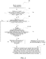
- FIG. 2 is a flow chart of the second embodiment of a keystone correction method for a projection terminal in accordance with the present invention. As shown in FIG. 2 , the method includes the following steps.
- step 200 the position of the projector is fixed.
- step 201 whether the position of the projector is fixed may be detected by using the following manners.
- the projector projects light
- it is detected whether the included angle between the projection centerline of the projector and the horizontal plane changes. If the included angle between the projection centerline of the projector and the horizontal plane changes, the process ends. And when there is no change in the included angle between the projection centerline of the projector and the horizontal plane, step 201 will be performed. If the included angle between the projection centerline of the projector and the horizontal plane does not change, it shows that the position of the projector has been fixed, and step 201 will be performed. Thus, only when the position of the projector position is fixed, subsequent steps can be performed. When the position of the projector changes due to various reasons, the keystone correction for the projector needs to be re-performed.
- step 201 when the projector projects light, the include angle between the projection centerline of the projector and the horizontal plane is obtained by measuring. If the included angle between the projection centerline of the projector and the horizontal plane is between 0° to 45°, it is determined that the direction of the projection plane is vertical, i.e., the projection plane is perpendicular to the horizontal plane. If the included angle between the projection centerline of the projector and the horizontal plane is greater than 45° and less than 90°, the step 202 will be performed.
- the projection centerline of the projector may direct towards an upper inclined side of or just above the horizontal plane, or direct towards a lower inclined side of or just below the horizontal plane.
- the projection plane may be a projection screen perpendicular to the horizontal plane, a wall, a ceiling or a projection screen parallel to the horizontal plane.
- the projection plane may be a projection screen perpendicular to the horizontal plane, a wall, a floor or a projection screen parallel to the horizontal plane.
- the include angle between the projection centerline of the projector and the horizontal plane may be measured by an angle measurement module, which is located inside the projector.
- the angle measurement module includes, but is not limited to, a gyroscope and an accelerometer.
- step 202 among all projection lines from the projector to the projection plane, if a projection angle of a projection line, of which the projection angle is maximum, is greater than or equal to 90°, then it is determined that the direction of the projection plane is horizontal; and if the projection angle of the projection line, of which the projection angle is maximum, is less than 90°, the step 203 will be performed.
- the projection plane is a vertical projection plane according to geometrical analysis. In this case, if the projection plane is the vertical projection plane, the projection line of which the projection angle is maximum cannot be projected onto the projection plane.
- the projection centerline of the projector directs towards the upper inclined side of or just above the horizontal plane.
- FIG. 3 is a schematic diagram of the first principle of determining the direction of the projection plane in the second embodiment of the keystone correction method for the projection terminal in accordance with the present invention.
- a point O represents the position of the projector
- a vertical line represents a vertical projection plane
- three half-lines through the point O represent a projection line of which the projection angle is maximum, a projection centerline and a projection line of which the projection angle is minimum, respectively.
- the projection centerline of the projector may direct towards the upper inclined side of the horizontal plane and the projection angle of the projection line, of which the projection angle is maximum, is greater than 90°, it is apparent that the projection line of which the projection angle is maximum does not intersect with the vertical projection plane.
- the projection centerline of the projector directs towards the lower inclined side of or just below the horizontal plane.
- FIG. 4 is a schematic diagram of a second principle of determining the direction of the projection plane in the second embodiment of the keystone correction method for the projection terminal in accordance with the present invention.
- a point P represents the position of the projector
- a vertical line represents a vertical projection plane
- three half-lines through the point P represent a projection line of which the projection angle is maximum, a projection centerline and a projection line of which the projection angle is minimum, respectively.
- the projection centerline of the projector may direct towards the lower inclined side of the horizontal plane and the range of the projection angle of the projection line of the projection terminal is from 0° to 180°, i.e., the projection angle of the projection line of the projection terminal is a positive value.
- the projection angle of the projection line, of which the projection angle is maximum is greater than 90°, and it is apparent that the projection line of which the projection angle is maximum does not intersect the vertical projection plane.
- two projection lines are selected from all projection lines from the projector to the projection plane, i.e., a projection line of which the projection angle is maximum among all projection lines from the projector to the projection plane, and a projection line of which the projection angle is minimum among all projection lines from the projector to the projection plane.
- a distance of the projector to the projection plane along the projection line of which the projection angle is maximum and a distance of the projector to the projection plane along the projection line of which the projection angle is minimum are obtained.
- the projection line of which the projection angle is maximum among all the projection lines from the projector to the projection plane is an upper projection boundary in all projection lines from the projector to the projection plane
- the projection line of which the projection angle is minimum among all the projection lines from the projector to the projection plane is a lower projection boundary in all projection lines from the projector to the projection plane.
- the distance of the projector to the projection plane along each of the projection lines may be measured by a distance measuring instrument, which is located inside the projector.
- the distance measuring instrument includes, but is not limited to, a laser distance measuring instrument, an infrared distance measuring instrument or a ultrasonic distance measuring instrument.
- the distance measuring instrument may be rotated according to the projection angle of the projection line, to further measure a distance of the corresponding projector to the projection plane at a corresponding projection angle.
- a single or two distance measuring instruments may be used to measure the distances of the projector to the projection plane along the two selected projection lines.
- the distance measuring instrument measures the distances of the projector to the projection plane along the two projection lines in sequence.
- one of the two distance measuring instruments measures the distance of the projector to the projection plane along one of the two selected projection lines, and at the same time, the other distance measuring instrument measures the distance of the projector to the projection plane along the other of the two selected projection lines.
- step 204 it is determined whether the distance of the projector to the projection plane along the projection line of which the projection angle is minimum is greater than the distance of the projector to the projection plane along the projection line of which the projection angle is maximum. If yes, it is determined that the direction of the projection plane is horizontal, step 205 will be performed; and if not, it is determined that the direction of the projection plane is vertical, step 205 will be performed.
- the projection centerline of the projector directs towards the upper inclined side of or just above the horizontal plane.
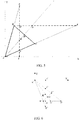
- FIG. 5 is a schematic diagram of a third principle of determining the direction of the projection plane in the second embodiment of the keystone correction method for the projection terminal in accordance with the present invention.
- a point A represents the position of the projector
- a line segment BF represents a horizontal projection plane
- a line segment EI represents a vertical projection plane
- a half-line AD (a half-line emitting from the point A and going through a point D) represents the projection centerline of the projector.
- the projection angle of the projection centerline of the projector is an included angle between the half-line AD and the positive direction of X-axis.
- the included angle between the half-line AD and the horizontal plane is greater than 45° and less than 90°, i.e., the included angle between the half-line AD and the positive direction of X-axis is greater than 45° and less than 90°.
- a half-line AB (a half-line emitting from the point A and going through a point B) represents the projection line of which the projection angle is maximum among all projection lines from the projector to the projection plane, and the projection angle of the projection line of which the projection angle is maximum among all projection lines from the projector to the projection plane is an included angle between the half-line AB and the positive direction of X-axis.
- a half-line AC (a half-line emitting from the point A and going through a point C) represents the projection line of which the projection angle is minimum among all projection lines from the projector to the projection plane, and the projection angle of the projection line of which the projection angle is minimum among all projection lines from the projector to the projection plane is an included angle between the half-line AC and the positive direction of X-axis.
- the projection plane is a horizontal projection plane represented by the line segment BF, as shown in FIG. 5 , a distance of the projector to the horizontal projection plane along the projection centerline of the projector is the length of the line segment AG, and a distance of the projector to the horizontal projection plane along the half-line AC is the length of the line segment AF, and a distance of the projector to the horizontal projection plane along the half-line AB is the length of the line segment AB. Since the included angle between the half-line AD and the horizontal plane is greater than 45° and less than 90°, an angle ABF is an obtuse angle, and similarly, an angle AGF is an obtuse angle.
- the length of the line segment AF is greater than the length of the line segment AG, and the length of the line segment AG is greater than the length of the line segment AB, i.e., the distance of the projector to the projection plane along the projection line of which the projection angle is minimum is greater than the distance of the projector to the projection plane along the projection line of which the projection angle is maximum.
- the projection plane is a vertical projection plane represented by the line segment EI, as shown in FIG. 5 , the distance of the projector to the horizontal projection plane along the projection centerline of the projector is the length of the line segment AK, and the distance of the projector to the horizontal projection plane along the half-line AC is the length of the line segment AJ, and the distance of the projector to the horizontal projection plane along the half-line AB is the length of the line segment AE. Since the included angle between the half-line AD and the horizontal plane is greater than 45° and less than 90°, an angle AKE is known to be an obtuse angle according to geometrical relationship, and similarly, an angle AJE is an obtuse angle.
- the length of the line segment AE is greater than the length of the line segment AK
- the length of the line segment AK is greater than the length of the line segment AJ, i.e., the distance of the projector to the projection plane along the projection line of which the projection angle is minimum is less than the distance of the projector to the projection plane along the projection line of which the projection angle is maximum.
- the projection centerline of the projector directs towards the lower inclined side of or just below the horizontal plane.
- FIG. 6 is a schematic diagram of a fourth principle of determining the direction of the projection plane in the second embodiment of the keystone correction method for the projection terminal in accordance with the present invention.
- a point A' represents the position of the projector
- the line segment B'F' represents a horizontal projection plane
- the line segment E'I' represents a vertical projection plane
- a half-line A'D' (a half-line emitting from the point A' and going through a point D') represents the projection centerline of the projector.
- the projection angle of the projection centerline of the projector is an included angle between the half-line A'D' and the positive direction of X-axis and takes a positive value.
- the included angle between the half-line A'D' and the horizontal plane is greater than 45° and less than 90°, i.e., the included angle between the half-line A'D' and the positive direction of X-axis is greater than 45° and less than 90°.
- a half-line A'B' (a half-line emitting from the point A' and going through a point B') represents the projection line of which the projection angle is maximum among all projection lines from the projector to the projection plane, and the projection angle of the projection line of which the projection angle is maximum among all projection lines from the projector to the projection plane is an included angle between the half-line A'B' and the positive direction of X-axis.
- a half-line A'C' (a half-line emitting from the point A' and going through a point C') represents the projection line of which the projection angle is minimum among all projection lines from the projector to the projection plane, and the projection angle of the projection line of which the projection angle is minimum among all projection lines from the projector to the projection plane is an included angle between the half-line A'C' and the positive direction of X-axis.
- the projection plane is a horizontal projection plane represented by the line segment B'F', as shown in FIG. 6 , a distance of the projector to the horizontal projection plane along the projection centerline of the projector is the length of the line segment A'G', and a distance of the projector to the horizontal projection plane along the half-line A'C' is the length of the line segment A'F', and a distance of the projector to the horizontal projection plane along the half-line A'B' is the length of the line segment A'B'.
- an angle A'B'F' is an obtuse angle
- an angle A'G'F' is an obtuse angle
- the length of the line segment A'F' is greater than the length of the line segment A'G'
- the length of the line segment A'G' is greater than the length of the line segment A'B', i.e., the distance of the projector to the projection plane along the projection line of which the projection angle is minimum is greater than the distance of the projector to the projection plane along the projection line of which the projection angle is maximum.
- the projection plane is a vertical projection plane represented by the line segment E'I', as shown in FIG. 6
- the distance of the projector to the vertical projection plane along the projection centerline of the projector is the length of the line segment A'K'
- the distance of the projector to the horizontal projection plane along the half-line A'C' is the length of the line segment A'J'
- the distance of the projector to the horizontal projection plane along the half-line A'B' is the length of the line segment A'E'.
- an angle A'K'E' is known to be an obtuse angle according to geometrical relationship, and similarly, an angle A'J'E' is an obtuse angle.
- the length of the line segment A'E' is greater than the length of the line segment A'K'
- the length of the line segment A'K' is greater than the length of the line segment A'J', i.e., the distance of the projector to the projection plane along the projection line of which the projection angle is minimum is less than the distance of the projector to the projection plane along the projection line of which the projection angle is maximum.
- step 205 the included angle between the projection centerline of the projector and the projection plane is obtained. If the direction of the projection plane is horizontal, then the included angle between the projection centerline of the projector and the projection plane is equal to the included angle between the projector and the horizontal plane. If the direction of the projection plane is vertical, then the included angle between the projection centerline of the projector and the projection plane is equal to 90° minus the included angle between the projector and the horizontal plane.
- the included angle between the projection centerline of the projector and the projection plane is 74°, and if the direction of the projection plane is horizontal, then the included angle between the projection centerline of the projector and the projection plane is 74°; and if the direction of the projection plane is vertical, then the included angle between the projection centerline of the projector and the projection plane is 16°.
- Keystone correction for the projector is performed according to the included angle between the projection centerline of the projector and the projection plane.
- a variety of existing implementation manners may be used to perform the keystone correction for the projector according to the included angle between the projection centerline of the projector and the projection plane, and will not be repeated herein.
- FIG. 7 is a structural block diagram of a keystone correction device for a projection terminal in accordance with an embodiment of the present invention. As shown in FIG. 7 , the device includes a determination module 700 and a keystone correction module 701.
- the determination module 700 is configured to, when an included angle between a projection centerline of the projection terminal and a horizontal plane is greater than a set acute angle, determine a direction of a projection plane according to a size relationship between a distance of the projection terminal to the projection plane along a first projection line and a distance of the projection terminal to the projection plane along a second projection line.
- the first projection line and the second projection line have different projection angles.
- the keystone correction module 701 is configured to perform keystone correction for the projection terminal according to the direction of the projection plane.
- the determination module 700 is configured to obtain the distance of the projection terminal to the projection plane along the first projection line and the distance of the projection terminal to the projection plane along the second projection line; when a projection angle of the first projection line is less than a projection angle of the second projection line, if the distance of the projection terminal to the projection plane along the first projection line is greater than the distance of the projection terminal to the projection plane along the second projection line, the direction of the projection plane is horizontal; otherwise the direction of the projection plane is vertical; and when the projection angle of the first projection line is greater than the projection angle of the second projection line, if the distance of the projection terminal to the projection plane along the first projection line is less than the distance of the projection terminal to the projection plane along the second projection line, the direction of the projection plane is horizontal; otherwise the direction of the projection plane is vertical.
- the determination module may obtain in sequence the distance of the projection terminal to the projection plane along the first projection line and the distance of the projection terminal to the projection plane along the second projection line, or may obtain simultaneously the distance of the projection terminal to the projection plane along the first projection line and the distance of the projection terminal to the projection plane along the second projection line.
- the first projection line and the second projection line may be any two of the following three projection lines: a projection line of which a projection angle is maximum among all projection lines from the projection terminal to the projection plane, and a projection line of which a projection angle is minimum among projection lines from the projection terminal to the projection plane, and the projection centerline of the projection terminal.
- the keystone correction module 701 is configured to obtain an angle between the projection centerline of the projection terminal and the projection plane according to the direction of the projection plane and an included angle between the projection centerline of the projection terminal and the horizontal plane; and perform the keystone correction for the projection terminal based on the angle between the projection centerline of the projection terminal and the projection plane.
- both the determination module 700 and keystone correction module 701 may be implemented by a central processing unit (CPU), a microprocessor unit (MPU), a digital signal processor (DSP) or a field programmable gate array (FPGA) located in the projection terminal.
- CPU central processing unit
- MPU microprocessor unit
- DSP digital signal processor
- FPGA field programmable gate array
- An embodiment of the present invention further provides a projection terminal including any keystone correction device for the projection terminal in accordance with the third embodiment of the present invention.
- An embodiment of the present invention further provides a computer storage medium having computer-executable instructions stored therein, which are used to carry out the method in accordance with the embodiments described above, such as, specifically, the methods described in FIG. 1 and/or FIG. 2 .
- the computer storage medium described in this embodiment may be a hard disk, optical disk, U disk or magnetic tape, optionally, a non-transient storage medium.
Landscapes
- Engineering & Computer Science (AREA)
- Multimedia (AREA)
- Signal Processing (AREA)
- Physics & Mathematics (AREA)
- Geometry (AREA)
- Projection Apparatus (AREA)
- Transforming Electric Information Into Light Information (AREA)
Claims (10)
- Verfahren zur Trapezkorrektur für ein Projektionsdatenendgerät, welches umfasst,
dass, wenn ein Winkel zwischen einer Projektionsmittellinie des Projektionsdatenendgeräts und einer horizontalen Ebene größer als ein festgelegter spitzer Winkel ist, bestimmt wird, ob eine Richtung einer Projektionsebene entsprechend einer Größenbeziehung zwischen einem Abstand des Projektionsdatenendgeräts zu der Projektionsebene entlang einer ersten Projektionslinie und einem Abstand des Projektionsdatenendgeräts zu der Projektionsebene entlang einer zweiten Projektionslinie (100) horizontal oder vertikal ist, wobei die erste Projektionslinie und die zweite Projektionslinie unterschiedliche Projektionswinkel in einer vertikaler Richtung aufweisen; und
dass, wenn der Winkel zwischen der Projektionsmittellinie des Projektionsdatenendgeräts und der horizontalen Ebene nicht größer als der eingestellte spitze Winkel ist, bestimmt wird, dass die Richtung der Projektionsebene vertikal ist; und
dass eine Trapezkorrektur für das Projektionsdatenendgerät gemäß der Richtung der Projektionsebene (101) durchgeführt wird;
wobei das Bestimmen, ob eine Richtung einer Projektionsebene horizontal oder vertikal ist, gemäß einer Größenbeziehung zwischen einem Abstand des Projektionsdatenendgeräts zu der Projektionsebene entlang einer ersten Projektionslinie und einem Abstand des Projektionsdatenendgeräts zu der Projektionsebene entlang einer zweiten Projektionslinie umfasst,
dass der Abstand des Projektionsdatenendgeräts zu der Projektionsebene entlang der ersten Projektionslinie und des Abstands des Projektionsdatenendgeräts zu der Projektionsebene entlang der zweiten Projektionslinie erhalten wird; und
dass, wenn ein Projektionswinkel der ersten Projektionslinie kleiner als ein Projektionswinkel der zweiten Projektionslinie ist, die Projektionswinkel Winkel in Bezug auf eine horizontale Ebene sind, und dass, wenn der Abstand des Projektionsdatenendgeräts zu der Projektionsebene entlang der ersten Projektionslinie größer als der Abstand des Projektionsdatenendgeräts zu der Projektionsebene entlang der zweiten Projektionslinie ist, die Richtung der Projektionsebene horizontal ist; wobei andernfalls die Richtung der Projektionsebene vertikal ist; und
dass, wenn der Projektionswinkel der ersten Projektionslinie größer als der Projektionswinkel der zweiten Projektionslinie ist, wenn der Abstand des Projektionsdatenendgeräts zu der Projektionsebene entlang der ersten Projektionslinie kleiner als der Abstand des Projektionsdatenendgeräts zu der Projektionsebene entlang der zweiten Projektionslinie ist, die Richtung der Projektionsebene horizontal ist; wobei andernfalls die Richtung der Projektionsebene vertikal ist. - Verfahren nach Anspruch 1, wobei das Erhalten des Abstands des Projektionsdatenendgeräts zu der Projektionsebene entlang der ersten Projektionslinie und des Abstands des Projektionsdatenendgeräts zu der Projektionsebene entlang der zweiten Projektionslinie umfasst,
dass nacheinander der Abstand des Projektionsdatenendgeräts zu der Projektionsebene entlang der ersten Projektionslinie und der Abstand des Projektionsdatenendgeräts zu der Projektionsebene entlang der zweiten Projektionslinie erhalten wird, oder dass gleichzeitig der Abstand des Projektionsdatenendgeräts zu der Projektionsebene entlang der erste Projektionslinie und der Abstand des Projektionsdatenendgeräts zu der Projektionsebene entlang der zweiten Projektionslinie erhalten wird. - Verfahren nach einem der Ansprüche 1 bis 2, wobei die erste Projektionslinie und die zweite Projektionslinie zwei beliebige der folgenden drei Projektionslinien sind: eine Projektionslinie, deren Projektionswinkel unter allen Projektionslinien von dem Projektionsdatenendgeräts zu der Projektionsebene maximal ist, und eine Projektionslinie, deren Projektionswinkel unter allen Projektionslinien von dem Projektionsdatenendgeräts zu der Projektionsebene minimal ist, und die Projektionsmittellinie des Projektionsdatenendgeräts.
- Verfahren nach einem der Ansprüche 1 bis 2, wobei das Durchführen einer Trapezkorrektur für das Projektionsdatenendgerät gemäß der Richtung der Projektionsebene umfasst:ein Erhalten eines Winkels zwischen der Projektionsmittellinie des Projektionsdatenendgeräts und der Projektionsebene gemäß der Richtung der Projektionsebene und dem Winkel zwischen der Projektionsmittellinie des Projektionsdatenendgeräts und der horizontalen Ebene; undein Durchführen der Trapezkorrektur für das Projektionsdatenendgerät basierend auf dem Winkel zwischen der Projektionsmittellinie des Projektionsdatenendgeräts und der Projektionsebene.
- Vorrichtung zur Trapezkorrektur für ein Projektionsdatenendgerät, welches ein Bestimmungsmodul und ein Trapezkorrekturmodul aufweist,
wobei das Bestimmungsmodul (700) ausgestaltet ist, um gemäß einer Größenbeziehung zwischen einem Abstand des Projektionsdatenendgeräts zu der Projektionsebene entlang einer ersten Projektionslinie und einem Abstand des Projektionsdatenendgeräts zu der Projektionsebene entlang einer zweiten Projektionslinie, zu bestimmen, ob eine Richtung einer Projektionsebene horizontal oder vertikal ist, wenn ein Winkel zwischen einer Projektionsmittellinie des Projektionsdatenendgeräts und einer horizontalen Ebene größer als ein festgelegter spitzer Winkel ist, wobei die erste Projektionslinie und die zweite Projektionslinie unterschiedliche Projektionswinkel in einer vertikalen Richtung aufweisen; und
wobei, wenn der Winkel zwischen der Projektionsmittellinie des Projektionsdatenendgeräts und der horizontalen Ebene nicht größer als der eingestellte spitze Winkel ist, bestimmt wird, dass die Richtung der Projektionsebene vertikal ist, und
wobei das Trapezkorrekturmodul (701) ausgestaltet ist, um eine Trapezkorrektur für das Projektionsdatenendgerät gemäß der Richtung der Projektionsebene durchzuführen,
wobei das Bestimmungsmodul ausgestaltet ist, dass falls der Winkel zwischen der Projektionsmittellinie des Projektionsdatenendgeräts und einer horizontalen Ebene größer als der eingestellte spitze Winkel ist, um den Abstand des Projektionsdatenendgeräts zu der Projektionsebene entlang der ersten Projektionslinie und des Abstand des Projektionsdatenendgeräts zu der Projektionsebene entlang der zweiten Projektionslinie zu erhalten; und
wobei, wenn ein Projektionswinkel der ersten Projektionslinie kleiner als ein Projektionswinkel der zweiten Projektionslinie ist, wenn der Abstand des Projektionsdatenendgeräts zu der Projektionsebene entlang der ersten Projektionslinie größer als der Abstand des Projektionsdatenendgeräts zu der Projektionsebene entlang der zweiten Projektionslinie ist, bestimmt wird, dass die Richtung der Projektionsebene horizontal ist, und andernfalls bestimmt wird, dass die Richtung der Projektionsebene vertikal ist; und wobei, wenn der Projektionswinkel der ersten Projektionslinie größer als der Projektionswinkel der zweiten Projektionslinie ist, wenn der Abstand des Projektionsdatenendgeräts zu der Projektionsebene entlang der ersten Projektionslinie kleiner als der Abstand des Projektionsdatenendgeräts zu der Projektionsebene entlang der zweiten Projektionslinie ist, bestimmt wird, dass die Richtung der Projektionsebene horizontal ist, und andernfalls bestimmt wird, dass die Richtung der Projektionsebene vertikal ist. - Vorrichtung nach Anspruch 5, wobei das Bestimmungsmodul ausgestaltet ist, um nacheinander den Abstand des Projektionsdatenendgeräts zu der Projektionsebene entlang der ersten Projektionslinie und den Abstand des Projektionsdatenendgeräts zu der Projektionsebene entlang der zweiten Projektionslinie zu erhalten, oder um gleichzeitig den Abstand des Projektionsdatenendgeräts zu der Projektionsebene entlang der ersten Projektionslinie und den Abstand des Projektionsdatenendgeräts zu der Projektionsebene entlang der zweiten Projektionslinie zu erhalten.
- Vorrichtung nach einem der Ansprüche 5 bis 6, wobei die erste Projektionslinie und die zweite Projektionslinie zwei beliebige von drei folgenden Projektionslinien sind: eine Projektionslinie, deren Projektionswinkel unter allen Projektionslinien von dem Projektionsdatenendgerät zu der Projektionsebene maximal ist, und eine Projektionslinie, deren Projektionswinkel unter allen Projektionslinien von dem Projektionsdatenendgerät zu der Projektionsebene minimal ist, und die Projektionsmittellinie des Projektionsdatenendgeräts ist.
- Vorrichtung nach einem der Ansprüche 5 bis 6, wobei das Trapezkorrekturmodul ausgestaltet ist, um einen Winkel zwischen der Projektionsmittellinie des Projektionsdatenendgeräts und der Projektionsebene gemäß der Richtung der Projektionsebene und dem Winkel zwischen der Projektionsmittellinie des Projektionsdatenendgeräts und der horizontalen Ebene zu erhalten; und um die Trapezkorrektur für das Projektionsterminal basierend auf dem Winkel zwischen der Projektionsmittellinie des Projektionsdatenendgeräts und der Projektionsebene durchzuführen.
- Projektionsdatenendgerät, welches die Vorrichtung nach einem der Ansprüche 5 bis 8 aufweist.
- Computerspeichermedium, in dem computerausführbare Anweisungen gespeichert sind, die, wenn sie von einem Computer ausgeführt werden, den Computer veranlassen, das Verfahren gemäß einem der Ansprüche 1 bis 4 auszuführen.
Applications Claiming Priority (2)
| Application Number | Priority Date | Filing Date | Title |
|---|---|---|---|
| CN201510391656.5A CN106331666B (zh) | 2015-07-03 | 2015-07-03 | 一种投影终端梯形校正方法、装置及投影终端 |
| PCT/CN2015/088299 WO2017004871A1 (zh) | 2015-07-03 | 2015-08-27 | 投影终端梯形校正方法、装置、投影终端和存储介质 |
Publications (3)
| Publication Number | Publication Date |
|---|---|
| EP3306919A1 EP3306919A1 (de) | 2018-04-11 |
| EP3306919A4 EP3306919A4 (de) | 2018-07-18 |
| EP3306919B1 true EP3306919B1 (de) | 2020-09-30 |
Family
ID=57684776
Family Applications (1)
| Application Number | Title | Priority Date | Filing Date |
|---|---|---|---|
| EP15897527.6A Active EP3306919B1 (de) | 2015-07-03 | 2015-08-27 | Verfahren und vorrichtung zur trapezkorrektur bei einem projektionsendgerät sowie projektionsendgerät und speichermedium |
Country Status (4)
| Country | Link |
|---|---|
| US (1) | US10645354B2 (de) |
| EP (1) | EP3306919B1 (de) |
| CN (1) | CN106331666B (de) |
| WO (1) | WO2017004871A1 (de) |
Families Citing this family (6)
| Publication number | Priority date | Publication date | Assignee | Title |
|---|---|---|---|---|
| CN107343186A (zh) * | 2017-06-13 | 2017-11-10 | 北京小米移动软件有限公司 | 投影设备控制方法及装置 |
| CN109587458B (zh) * | 2017-09-29 | 2021-10-15 | 中强光电股份有限公司 | 投影系统及其自动设定方法 |
| EP3922462B1 (de) | 2020-06-08 | 2023-03-01 | Agfa Offset Bv | Lithografischer photopolymerer druckplattenvorläufer mit verbesserter tageslichtstabilität |
| CN114390261B (zh) * | 2020-10-20 | 2023-10-24 | 深圳海翼智新科技有限公司 | 投影系统及其梯形校正方法、具有存储功能的装置 |
| CN114222102A (zh) * | 2022-02-08 | 2022-03-22 | 峰米(重庆)创新科技有限公司 | 投影设备及其调整方法、控制装置、可读存储介质 |
| CN117440139B (zh) * | 2023-12-19 | 2024-03-12 | 深圳新智联软件有限公司 | 一种用于投影生成自动梯形校正方法、装置、设备及介质 |
Family Cites Families (16)
| Publication number | Priority date | Publication date | Assignee | Title |
|---|---|---|---|---|
| WO2003107090A1 (en) * | 2002-06-12 | 2003-12-24 | Silicon Optix, Inc. | Automatic keystone correction system and method |
| JP4155890B2 (ja) * | 2003-07-15 | 2008-09-24 | カシオ計算機株式会社 | プロジェクタ、プロジェクタの傾斜角度取得方法及び投影像補正方法 |
| JP3772870B2 (ja) * | 2003-08-25 | 2006-05-10 | カシオ計算機株式会社 | 投影装置、投影方法及びプログラム |
| JP4398702B2 (ja) | 2003-11-06 | 2010-01-13 | フジノン株式会社 | プロジェクタ |
| JP3960390B2 (ja) * | 2004-05-31 | 2007-08-15 | Necディスプレイソリューションズ株式会社 | 台形歪み補正装置を備えたプロジェクタ |
| JP2007067495A (ja) * | 2005-08-29 | 2007-03-15 | Toshiba Corp | プロジェクタ装置 |
| DE102008043189A1 (de) * | 2007-12-03 | 2009-06-04 | Robert Bosch Gmbh | Projektion mit dynamischer Anpassung der Bilddaten |
| JP2010028412A (ja) * | 2008-07-18 | 2010-02-04 | Seiko Epson Corp | 電子機器 |
| CN102271237A (zh) * | 2011-02-25 | 2011-12-07 | 鸿富锦精密工业(深圳)有限公司 | 投影装置及其矫正梯形失真的方法 |
| WO2012157546A1 (ja) * | 2011-05-13 | 2012-11-22 | ローム株式会社 | プロジェクタ |
| JP5958072B2 (ja) * | 2012-05-18 | 2016-07-27 | 株式会社Jvcケンウッド | 投射装置および画像補正方法 |
| CN102650805A (zh) * | 2012-05-25 | 2012-08-29 | 深圳市众进思创科技开发有限公司 | 一种投影仪及其多方向投影图像的校正方法 |
| CN102998885B (zh) * | 2012-11-20 | 2015-09-02 | 芜湖市安曼特微显示科技有限公司 | 对投影仪投影图像失真校正的方法 |
| WO2014115884A1 (ja) * | 2013-01-28 | 2014-07-31 | 株式会社Jvcケンウッド | 投射装置、画像補正方法およびプログラム |
| JP2015126340A (ja) * | 2013-12-26 | 2015-07-06 | ソニー株式会社 | 画像処理方法並びに画像投影装置 |
| CN103974048B (zh) * | 2014-04-28 | 2016-05-04 | 京东方科技集团股份有限公司 | 控制可穿戴设备投影的方法及装置、可穿戴设备 |
-
2015
- 2015-07-03 CN CN201510391656.5A patent/CN106331666B/zh active Active
- 2015-08-27 US US15/739,786 patent/US10645354B2/en active Active
- 2015-08-27 EP EP15897527.6A patent/EP3306919B1/de active Active
- 2015-08-27 WO PCT/CN2015/088299 patent/WO2017004871A1/zh not_active Ceased
Non-Patent Citations (1)
| Title |
|---|
| None * |
Also Published As
| Publication number | Publication date |
|---|---|
| EP3306919A4 (de) | 2018-07-18 |
| US20180192015A1 (en) | 2018-07-05 |
| WO2017004871A1 (zh) | 2017-01-12 |
| CN106331666A (zh) | 2017-01-11 |
| EP3306919A1 (de) | 2018-04-11 |
| CN106331666B (zh) | 2020-02-07 |
| US10645354B2 (en) | 2020-05-05 |
Similar Documents
| Publication | Publication Date | Title |
|---|---|---|
| US10645354B2 (en) | Projection terminal keystone correction method and device, and projection terminal and storage medium | |
| US10212403B2 (en) | Method and apparatus for realizing trapezoidal distortion correction of projection plane | |
| US8805015B2 (en) | Electronic device and method for measuring point cloud of object | |
| US10069186B2 (en) | Method and device for obtaining antenna engineering parameter and system | |
| CN109855568B (zh) | 自动驾驶传感器的检测方法、装置、电子设备及存储介质 | |
| CN103064565B (zh) | 一种定位方法及电子设备 | |
| JP2019215811A (ja) | 投影システム、画像処理装置および投影方法 | |
| CN107911680A (zh) | 投影设备校正方法、装置及投影设备 | |
| CN107197222A (zh) | 生成投影设备的校正信息的方法及装置 | |
| CN108111828A (zh) | 投影设备校正方法、装置及投影设备 | |
| CN105627954A (zh) | 夹角测量方法、装置及夹角调节方法、装置 | |
| CN109967893A (zh) | 一种激光切割补偿方法及激光切割系统 | |
| CN104679487A (zh) | 旋转台精度补偿系统及方法 | |
| CN108200416A (zh) | 投影设备中投影图像的坐标映射方法、装置及投影设备 | |
| JP6099023B2 (ja) | プロジェクタシステム | |
| CN105444701A (zh) | 一种区域面积的测量方法及装置 | |
| CN106441145A (zh) | 触摸屏玻璃膜的弧度测量方法与系统 | |
| US20210240196A1 (en) | Positioning apparatus, recording medium, and positioning method | |
| US9741135B2 (en) | Method for measuring object and smart device | |
| CN104732538B (zh) | 摄像头定位跟踪方法及相关系统 | |
| JP2015087692A (ja) | 姿勢検出装置とその制御方法、および、プロジェクタ | |
| KR101868043B1 (ko) | 3차원 방사선원 위치 측정 장치 및 방법 | |
| CN111951349A (zh) | 一种图形顶点类型的调整方法、装置及电子设备 | |
| US11433542B2 (en) | Calibration detecting apparatus, method, and program | |
| US9207076B2 (en) | Computing device and method for determining ricochet vectors of a probe of a coordinate measuring machine |
Legal Events
| Date | Code | Title | Description |
|---|---|---|---|
| STAA | Information on the status of an ep patent application or granted ep patent |
Free format text: STATUS: THE INTERNATIONAL PUBLICATION HAS BEEN MADE |
|
| PUAI | Public reference made under article 153(3) epc to a published international application that has entered the european phase |
Free format text: ORIGINAL CODE: 0009012 |
|
| STAA | Information on the status of an ep patent application or granted ep patent |
Free format text: STATUS: REQUEST FOR EXAMINATION WAS MADE |
|
| 17P | Request for examination filed |
Effective date: 20180102 |
|
| AK | Designated contracting states |
Kind code of ref document: A1 Designated state(s): AL AT BE BG CH CY CZ DE DK EE ES FI FR GB GR HR HU IE IS IT LI LT LU LV MC MK MT NL NO PL PT RO RS SE SI SK SM TR |
|
| AX | Request for extension of the european patent |
Extension state: BA ME |
|
| A4 | Supplementary search report drawn up and despatched |
Effective date: 20180615 |
|
| RIC1 | Information provided on ipc code assigned before grant |
Ipc: H04N 9/31 20060101AFI20180608BHEP |
|
| DAV | Request for validation of the european patent (deleted) | ||
| DAX | Request for extension of the european patent (deleted) | ||
| GRAP | Despatch of communication of intention to grant a patent |
Free format text: ORIGINAL CODE: EPIDOSNIGR1 |
|
| STAA | Information on the status of an ep patent application or granted ep patent |
Free format text: STATUS: GRANT OF PATENT IS INTENDED |
|
| INTG | Intention to grant announced |
Effective date: 20200414 |
|
| GRAS | Grant fee paid |
Free format text: ORIGINAL CODE: EPIDOSNIGR3 |
|
| GRAA | (expected) grant |
Free format text: ORIGINAL CODE: 0009210 |
|
| STAA | Information on the status of an ep patent application or granted ep patent |
Free format text: STATUS: THE PATENT HAS BEEN GRANTED |
|
| AK | Designated contracting states |
Kind code of ref document: B1 Designated state(s): AL AT BE BG CH CY CZ DE DK EE ES FI FR GB GR HR HU IE IS IT LI LT LU LV MC MK MT NL NO PL PT RO RS SE SI SK SM TR |
|
| REG | Reference to a national code |
Ref country code: CH Ref legal event code: EP Ref country code: GB Ref legal event code: FG4D |
|
| REG | Reference to a national code |
Ref country code: DE Ref legal event code: R096 Ref document number: 602015059994 Country of ref document: DE Ref country code: AT Ref legal event code: REF Ref document number: 1320020 Country of ref document: AT Kind code of ref document: T Effective date: 20201015 |
|
| REG | Reference to a national code |
Ref country code: IE Ref legal event code: FG4D |
|
| PG25 | Lapsed in a contracting state [announced via postgrant information from national office to epo] |
Ref country code: BG Free format text: LAPSE BECAUSE OF FAILURE TO SUBMIT A TRANSLATION OF THE DESCRIPTION OR TO PAY THE FEE WITHIN THE PRESCRIBED TIME-LIMIT Effective date: 20201230 Ref country code: HR Free format text: LAPSE BECAUSE OF FAILURE TO SUBMIT A TRANSLATION OF THE DESCRIPTION OR TO PAY THE FEE WITHIN THE PRESCRIBED TIME-LIMIT Effective date: 20200930 Ref country code: NO Free format text: LAPSE BECAUSE OF FAILURE TO SUBMIT A TRANSLATION OF THE DESCRIPTION OR TO PAY THE FEE WITHIN THE PRESCRIBED TIME-LIMIT Effective date: 20201230 Ref country code: GR Free format text: LAPSE BECAUSE OF FAILURE TO SUBMIT A TRANSLATION OF THE DESCRIPTION OR TO PAY THE FEE WITHIN THE PRESCRIBED TIME-LIMIT Effective date: 20201231 Ref country code: FI Free format text: LAPSE BECAUSE OF FAILURE TO SUBMIT A TRANSLATION OF THE DESCRIPTION OR TO PAY THE FEE WITHIN THE PRESCRIBED TIME-LIMIT Effective date: 20200930 Ref country code: SE Free format text: LAPSE BECAUSE OF FAILURE TO SUBMIT A TRANSLATION OF THE DESCRIPTION OR TO PAY THE FEE WITHIN THE PRESCRIBED TIME-LIMIT Effective date: 20200930 |
|
| REG | Reference to a national code |
Ref country code: AT Ref legal event code: MK05 Ref document number: 1320020 Country of ref document: AT Kind code of ref document: T Effective date: 20200930 |
|
| PG25 | Lapsed in a contracting state [announced via postgrant information from national office to epo] |
Ref country code: LV Free format text: LAPSE BECAUSE OF FAILURE TO SUBMIT A TRANSLATION OF THE DESCRIPTION OR TO PAY THE FEE WITHIN THE PRESCRIBED TIME-LIMIT Effective date: 20200930 Ref country code: RS Free format text: LAPSE BECAUSE OF FAILURE TO SUBMIT A TRANSLATION OF THE DESCRIPTION OR TO PAY THE FEE WITHIN THE PRESCRIBED TIME-LIMIT Effective date: 20200930 |
|
| REG | Reference to a national code |
Ref country code: NL Ref legal event code: MP Effective date: 20200930 |
|
| REG | Reference to a national code |
Ref country code: LT Ref legal event code: MG4D |
|
| PG25 | Lapsed in a contracting state [announced via postgrant information from national office to epo] |
Ref country code: CZ Free format text: LAPSE BECAUSE OF FAILURE TO SUBMIT A TRANSLATION OF THE DESCRIPTION OR TO PAY THE FEE WITHIN THE PRESCRIBED TIME-LIMIT Effective date: 20200930 Ref country code: SM Free format text: LAPSE BECAUSE OF FAILURE TO SUBMIT A TRANSLATION OF THE DESCRIPTION OR TO PAY THE FEE WITHIN THE PRESCRIBED TIME-LIMIT Effective date: 20200930 Ref country code: PT Free format text: LAPSE BECAUSE OF FAILURE TO SUBMIT A TRANSLATION OF THE DESCRIPTION OR TO PAY THE FEE WITHIN THE PRESCRIBED TIME-LIMIT Effective date: 20210201 Ref country code: RO Free format text: LAPSE BECAUSE OF FAILURE TO SUBMIT A TRANSLATION OF THE DESCRIPTION OR TO PAY THE FEE WITHIN THE PRESCRIBED TIME-LIMIT Effective date: 20200930 Ref country code: EE Free format text: LAPSE BECAUSE OF FAILURE TO SUBMIT A TRANSLATION OF THE DESCRIPTION OR TO PAY THE FEE WITHIN THE PRESCRIBED TIME-LIMIT Effective date: 20200930 Ref country code: LT Free format text: LAPSE BECAUSE OF FAILURE TO SUBMIT A TRANSLATION OF THE DESCRIPTION OR TO PAY THE FEE WITHIN THE PRESCRIBED TIME-LIMIT Effective date: 20200930 |
|
| PG25 | Lapsed in a contracting state [announced via postgrant information from national office to epo] |
Ref country code: IS Free format text: LAPSE BECAUSE OF FAILURE TO SUBMIT A TRANSLATION OF THE DESCRIPTION OR TO PAY THE FEE WITHIN THE PRESCRIBED TIME-LIMIT Effective date: 20210130 Ref country code: PL Free format text: LAPSE BECAUSE OF FAILURE TO SUBMIT A TRANSLATION OF THE DESCRIPTION OR TO PAY THE FEE WITHIN THE PRESCRIBED TIME-LIMIT Effective date: 20200930 Ref country code: ES Free format text: LAPSE BECAUSE OF FAILURE TO SUBMIT A TRANSLATION OF THE DESCRIPTION OR TO PAY THE FEE WITHIN THE PRESCRIBED TIME-LIMIT Effective date: 20200930 Ref country code: AT Free format text: LAPSE BECAUSE OF FAILURE TO SUBMIT A TRANSLATION OF THE DESCRIPTION OR TO PAY THE FEE WITHIN THE PRESCRIBED TIME-LIMIT Effective date: 20200930 Ref country code: AL Free format text: LAPSE BECAUSE OF FAILURE TO SUBMIT A TRANSLATION OF THE DESCRIPTION OR TO PAY THE FEE WITHIN THE PRESCRIBED TIME-LIMIT Effective date: 20200930 |
|
| PG25 | Lapsed in a contracting state [announced via postgrant information from national office to epo] |
Ref country code: SK Free format text: LAPSE BECAUSE OF FAILURE TO SUBMIT A TRANSLATION OF THE DESCRIPTION OR TO PAY THE FEE WITHIN THE PRESCRIBED TIME-LIMIT Effective date: 20200930 Ref country code: NL Free format text: LAPSE BECAUSE OF FAILURE TO SUBMIT A TRANSLATION OF THE DESCRIPTION OR TO PAY THE FEE WITHIN THE PRESCRIBED TIME-LIMIT Effective date: 20200930 |
|
| REG | Reference to a national code |
Ref country code: DE Ref legal event code: R097 Ref document number: 602015059994 Country of ref document: DE |
|
| PLBE | No opposition filed within time limit |
Free format text: ORIGINAL CODE: 0009261 |
|
| STAA | Information on the status of an ep patent application or granted ep patent |
Free format text: STATUS: NO OPPOSITION FILED WITHIN TIME LIMIT |
|
| PG25 | Lapsed in a contracting state [announced via postgrant information from national office to epo] |
Ref country code: DK Free format text: LAPSE BECAUSE OF FAILURE TO SUBMIT A TRANSLATION OF THE DESCRIPTION OR TO PAY THE FEE WITHIN THE PRESCRIBED TIME-LIMIT Effective date: 20200930 |
|
| 26N | No opposition filed |
Effective date: 20210701 |
|
| PG25 | Lapsed in a contracting state [announced via postgrant information from national office to epo] |
Ref country code: IT Free format text: LAPSE BECAUSE OF FAILURE TO SUBMIT A TRANSLATION OF THE DESCRIPTION OR TO PAY THE FEE WITHIN THE PRESCRIBED TIME-LIMIT Effective date: 20200930 |
|
| PG25 | Lapsed in a contracting state [announced via postgrant information from national office to epo] |
Ref country code: SI Free format text: LAPSE BECAUSE OF FAILURE TO SUBMIT A TRANSLATION OF THE DESCRIPTION OR TO PAY THE FEE WITHIN THE PRESCRIBED TIME-LIMIT Effective date: 20200930 |
|
| REG | Reference to a national code |
Ref country code: CH Ref legal event code: PL |
|
| PG25 | Lapsed in a contracting state [announced via postgrant information from national office to epo] |
Ref country code: MC Free format text: LAPSE BECAUSE OF FAILURE TO SUBMIT A TRANSLATION OF THE DESCRIPTION OR TO PAY THE FEE WITHIN THE PRESCRIBED TIME-LIMIT Effective date: 20200930 |
|
| REG | Reference to a national code |
Ref country code: BE Ref legal event code: MM Effective date: 20210831 |
|
| PG25 | Lapsed in a contracting state [announced via postgrant information from national office to epo] |
Ref country code: LI Free format text: LAPSE BECAUSE OF NON-PAYMENT OF DUE FEES Effective date: 20210831 Ref country code: CH Free format text: LAPSE BECAUSE OF NON-PAYMENT OF DUE FEES Effective date: 20210831 |
|
| PG25 | Lapsed in a contracting state [announced via postgrant information from national office to epo] |
Ref country code: IS Free format text: LAPSE BECAUSE OF FAILURE TO SUBMIT A TRANSLATION OF THE DESCRIPTION OR TO PAY THE FEE WITHIN THE PRESCRIBED TIME-LIMIT Effective date: 20210130 Ref country code: LU Free format text: LAPSE BECAUSE OF NON-PAYMENT OF DUE FEES Effective date: 20210827 |
|
| PG25 | Lapsed in a contracting state [announced via postgrant information from national office to epo] |
Ref country code: IE Free format text: LAPSE BECAUSE OF NON-PAYMENT OF DUE FEES Effective date: 20210827 Ref country code: BE Free format text: LAPSE BECAUSE OF NON-PAYMENT OF DUE FEES Effective date: 20210831 |
|
| PG25 | Lapsed in a contracting state [announced via postgrant information from national office to epo] |
Ref country code: HU Free format text: LAPSE BECAUSE OF FAILURE TO SUBMIT A TRANSLATION OF THE DESCRIPTION OR TO PAY THE FEE WITHIN THE PRESCRIBED TIME-LIMIT; INVALID AB INITIO Effective date: 20150827 |
|
| PG25 | Lapsed in a contracting state [announced via postgrant information from national office to epo] |
Ref country code: CY Free format text: LAPSE BECAUSE OF FAILURE TO SUBMIT A TRANSLATION OF THE DESCRIPTION OR TO PAY THE FEE WITHIN THE PRESCRIBED TIME-LIMIT Effective date: 20200930 |
|
| PG25 | Lapsed in a contracting state [announced via postgrant information from national office to epo] |
Ref country code: MK Free format text: LAPSE BECAUSE OF FAILURE TO SUBMIT A TRANSLATION OF THE DESCRIPTION OR TO PAY THE FEE WITHIN THE PRESCRIBED TIME-LIMIT Effective date: 20200930 |
|
| PG25 | Lapsed in a contracting state [announced via postgrant information from national office to epo] |
Ref country code: MT Free format text: LAPSE BECAUSE OF FAILURE TO SUBMIT A TRANSLATION OF THE DESCRIPTION OR TO PAY THE FEE WITHIN THE PRESCRIBED TIME-LIMIT Effective date: 20200930 |
|
| PGFP | Annual fee paid to national office [announced via postgrant information from national office to epo] |
Ref country code: DE Payment date: 20250702 Year of fee payment: 11 |
|
| PGFP | Annual fee paid to national office [announced via postgrant information from national office to epo] |
Ref country code: GB Payment date: 20250703 Year of fee payment: 11 |
|
| PGFP | Annual fee paid to national office [announced via postgrant information from national office to epo] |
Ref country code: FR Payment date: 20250703 Year of fee payment: 11 |
|
| PG25 | Lapsed in a contracting state [announced via postgrant information from national office to epo] |
Ref country code: TR Free format text: LAPSE BECAUSE OF FAILURE TO SUBMIT A TRANSLATION OF THE DESCRIPTION OR TO PAY THE FEE WITHIN THE PRESCRIBED TIME-LIMIT Effective date: 20200930 |