EP3306390B1 - Verfahren und vorrichtung zur ausführung einer trapezverzerrungskorrektur einer projektionsfläche - Google Patents
Verfahren und vorrichtung zur ausführung einer trapezverzerrungskorrektur einer projektionsfläche Download PDFInfo
- Publication number
- EP3306390B1 EP3306390B1 EP15882475.5A EP15882475A EP3306390B1 EP 3306390 B1 EP3306390 B1 EP 3306390B1 EP 15882475 A EP15882475 A EP 15882475A EP 3306390 B1 EP3306390 B1 EP 3306390B1
- Authority
- EP
- European Patent Office
- Prior art keywords
- projector
- included angle
- projection
- distance
- plane
- Prior art date
- Legal status (The legal status is an assumption and is not a legal conclusion. Google has not performed a legal analysis and makes no representation as to the accuracy of the status listed.)
- Active
Links
Images



Classifications
-
- H—ELECTRICITY
- H04—ELECTRIC COMMUNICATION TECHNIQUE
- H04N—PICTORIAL COMMUNICATION, e.g. TELEVISION
- H04N9/00—Details of colour television systems
- H04N9/12—Picture reproducers
- H04N9/31—Projection devices for colour picture display, e.g. using electronic spatial light modulators [ESLM]
- H04N9/3179—Video signal processing therefor
- H04N9/3185—Geometric adjustment, e.g. keystone or convergence
-
- G—PHYSICS
- G03—PHOTOGRAPHY; CINEMATOGRAPHY; ANALOGOUS TECHNIQUES USING WAVES OTHER THAN OPTICAL WAVES; ELECTROGRAPHY; HOLOGRAPHY
- G03B—APPARATUS OR ARRANGEMENTS FOR TAKING PHOTOGRAPHS OR FOR PROJECTING OR VIEWING THEM; APPARATUS OR ARRANGEMENTS EMPLOYING ANALOGOUS TECHNIQUES USING WAVES OTHER THAN OPTICAL WAVES; ACCESSORIES THEREFOR
- G03B21/00—Projectors or projection-type viewers; Accessories therefor
- G03B21/14—Details
-
- G—PHYSICS
- G03—PHOTOGRAPHY; CINEMATOGRAPHY; ANALOGOUS TECHNIQUES USING WAVES OTHER THAN OPTICAL WAVES; ELECTROGRAPHY; HOLOGRAPHY
- G03B—APPARATUS OR ARRANGEMENTS FOR TAKING PHOTOGRAPHS OR FOR PROJECTING OR VIEWING THEM; APPARATUS OR ARRANGEMENTS EMPLOYING ANALOGOUS TECHNIQUES USING WAVES OTHER THAN OPTICAL WAVES; ACCESSORIES THEREFOR
- G03B21/00—Projectors or projection-type viewers; Accessories therefor
- G03B21/14—Details
- G03B21/142—Adjusting of projection optics
-
- G—PHYSICS
- G03—PHOTOGRAPHY; CINEMATOGRAPHY; ANALOGOUS TECHNIQUES USING WAVES OTHER THAN OPTICAL WAVES; ELECTROGRAPHY; HOLOGRAPHY
- G03B—APPARATUS OR ARRANGEMENTS FOR TAKING PHOTOGRAPHS OR FOR PROJECTING OR VIEWING THEM; APPARATUS OR ARRANGEMENTS EMPLOYING ANALOGOUS TECHNIQUES USING WAVES OTHER THAN OPTICAL WAVES; ACCESSORIES THEREFOR
- G03B21/00—Projectors or projection-type viewers; Accessories therefor
- G03B21/14—Details
- G03B21/147—Optical correction of image distortions, e.g. keystone
-
- H—ELECTRICITY
- H04—ELECTRIC COMMUNICATION TECHNIQUE
- H04N—PICTORIAL COMMUNICATION, e.g. TELEVISION
- H04N5/00—Details of television systems
- H04N5/74—Projection arrangements for image reproduction, e.g. using eidophor
-
- H—ELECTRICITY
- H04—ELECTRIC COMMUNICATION TECHNIQUE
- H04N—PICTORIAL COMMUNICATION, e.g. TELEVISION
- H04N9/00—Details of colour television systems
- H04N9/12—Picture reproducers
- H04N9/31—Projection devices for colour picture display, e.g. using electronic spatial light modulators [ESLM]
- H04N9/3191—Testing thereof
- H04N9/3194—Testing thereof including sensor feedback
-
- H—ELECTRICITY
- H04—ELECTRIC COMMUNICATION TECHNIQUE
- H04N—PICTORIAL COMMUNICATION, e.g. TELEVISION
- H04N5/00—Details of television systems
- H04N5/74—Projection arrangements for image reproduction, e.g. using eidophor
- H04N5/7408—Direct viewing projectors, e.g. an image displayed on a video CRT or LCD display being projected on a screen
Definitions
- the present application relates to but is not limited to a projector technology.
- digital trapezoidal distortion correction can very well solve trapezoidal image distortion, and the practicability is very strong.
- some lines and character edges of an image become blurred and unsmooth and the definition is poor after the image is subjected to digital trapezoidal distortion correction, it is not suitable for applications which have high requirements on image accuracy, such as CAD drawing display.
- image distortion in a vertical direction caused during projection at an inclined angle can be corrected.
- Trapezoidal distortion correction includes vertical trapezoidal distortion correction and horizontal trapezoidal distortion correction.
- angles which can be corrected are limited in an automatic vertical trapezoidal distortion correction technology, a correction range is generally 0°-45°, projectors in the market usually reserve 5° and an actual range is 0°-40°. Since whether a projection plane is a wall or a ceiling cannot be recognized when an included angle between a projector and a horizontal plane exceeds 45° in the automatic vertical trapezoidal distortion correction technology in the related art, if the included angle between the projector and the horizontal angle exceeds 45°, the projection plane is a wall.
- the present invention provides a method and an apparatus for correcting trapezoidal distortion of a projection plane, which can automatically and accurately realize trapezoidal distortion correction.
- a method for correcting trapezoidal distortion of a projection plane is disclosed in independent claim 1.
- measuring the distance between the projector and the projection plane by using the rotatable range finder includes: measuring a first distance between a parallel direction of the projector and the projection plane and a second distance between a direction of the upper projection boundary of the projector and the projection plane by using the rotatable range finder.
- the step of measuring the trend of change in the distance between the projector and the projection plane by using the rotatable range finder includes:
- measuring the distance between the projector and the projection plane by using the rotatable range finder includes: measuring the second distance between the direction of the upper projection boundary of the projector and the projection plane and a third distance between a direction of a lower projection boundary of the projector and the projection plane.
- measuring the trend of change in the distance between the projector and the projection plane by using the rotatable range finder includes:
- the method further includes:
- determining the correction included angle according to the trend of change includes:
- measuring the trend of change in the distance between the projector and the projection plane by using the rotatable range finder further includes: determining that the multiple distances obtained through scanning do not have a trend of changing from great to small and then changing from small to great;
- a method for correcting trapezoidal distortion of a projection plane includes:
- measuring the distance between the projector and the projection plane by using the rotatable range finder includes: measuring a first distance between a parallel direction of the projector and the projection plane and a second distance between the direction of the upper projection boundary of the projector and the projection plane by using the rotatable range finder; and measuring the trend of change in the distance between the projector and the projection plane by using the rotatable range finder includes:
- measuring the distance between the projector and the projection plane by using the rotatable range finder includes: measuring a second distance between the direction of the upper projection boundary of the projector and the projection plane and a third distance between the direction of a lower projection boundary of the projector and the projection plane by using the rotatable range finder; and measuring the trend of change in the distance between the projector and the projection plane by using the rotatable range finder includes:
- the method further includes:
- determining the correction included angle according to the trend of change includes:
- a method for correcting trapezoidal distortion of a projection plane includes: scanning from a direction of any projection boundary to a direction of another projection boundary of a projector to obtain multiple distances between the projector and a projection plane; if the multiple distances obtained through scanning have a trend of changing from great to small and then changing from small to great, determining that the correction included angle is an included angle between the projector along a projection center line and the direction of the shortest distance; and correcting trapezoidal distortion according to the determined correction included angle.
- measuring the trend of change in the distance between the projector and the projection plane by using the rotatable range finder includes: determining that the multiple distances obtained through scanning have a trend of changing from great to small and then changing from small to great; and correspondingly, determining the correction included angle according to the trend of change includes: determining that the correction included angle is an included angle between the projector along a projection center line and the direction of the shortest distance, i.e., an actual included angle between the projector on the horizontal plane and the projection plane.
- measuring the trend of change in the distance between the projector and the projection plane by using the rotatable range finder further includes: determining that the multiple distances obtained through scanning do not have a trend of changing from great to small and then changing from small to great;
- the first judgment module is configured to: when the included angle between the projector and the horizontal plane is greater than a preset first included angle threshold and the included angle between the upper projection boundary of the projector and the horizontal plane is less than a second included angle threshold, measure the trend of change in the distance between the projector and the projection plane by using the rotatable range finder, and output a first notification or a second notification to the first processing module according to the trend of change.
- the first judgment module is configured to:
- the first judgment module is further configured to:
- the determination unit includes: a first scanning module, a second judgment module and a second processing module; and the correction unit includes: a second correction module, herein,
- the determination unit further includes a second scanning module; at this moment,
- a projector includes the apparatus for correcting trapezoidal distortion of the projection plane.
- a computer-readable storage medium stores computer-executable instructions used for executing any one of the above methods.
- the scheme of the present application includes: measuring a trend of change in a distance between a projector and a projection plane by using a rotatable range finder, and determining a correction included angle according to the obtained trend of change; and correcting trapezoidal distortion of the projection plane according to the determined correction included angle.
- the method includes: determining an included angle between a projector and a horizontal plane; and when the determined included angle between the projector and the horizontal plane is greater than a first included angle threshold and an included angle between an upper projection boundary of the projector and the horizontal plane is less than a second included angle threshold, measuring a trend of change in a distance between the projector and a projection plane by using a rotatable range finder, and determining a correction included angle according to the trend of change; and correcting trapezoidal distortion according to the determined correction included angle.
- the method includes: scanning from the direction of any projection boundary to the direction of another projection boundary of a projector to obtain multiple distances between the projector and a projection plane; if the multiple distances obtained through scanning have a trend of changing from great to small and then changing from small to great, determining that the correction included angle is an included angle between the projector along a projection center line and the direction of the shortest distance, i.e., an actual included angle between the projector on the horizontal plane and the projection plane; and correcting trapezoidal distortion according to the determined correction included angle.
- a method for correcting trapezoidal distortion of a projection plane includes the following steps.
- step 11 a trend of change in a distance between a projector and a projection plane is measured by using a rotatable range finder, and a correction included angle is determined according to the obtained trend of change.
- step 12 trapezoidal distortion of the projection plane is corrected according to the determined correction included angle.
- measuring the distance between the projector and the projection plane by using the rotatable range finder includes: measuring a first distance between a parallel direction of the projector and the projection plane and a second distance between the direction of an upper projection boundary of the projector and the projection plane by using the rotatable range finder.
- measuring the trend of change in the distance between the projector and the projection plane by using the rotatable range finder includes: if the trend of change from the first distance to the second distance is a decrease trend, indicating that the projection plane is in parallel with a horizontal plane, i.e., the projection plane is a ceiling; and if the trend of change from the first distance to the second distance is an increase trend, indicating that the projection plane is perpendicular to the horizontal plane, i.e., the projection plane is a wall.
- measuring the distance between the projector and the projection plane by using the rotatable range finder includes: measuring a second distance between the direction of an upper projection boundary of the projector and the projection plane and a third distance between the direction of a lower projection boundary of the projector and the projection plane.
- measuring the trend of change in the distance between the projector and the projection plane by using the rotatable range finder includes: if the second distance is less than the third distance, indicating that the projection plane is in parallel with the horizontal plane, i.e., the projection plane is a ceiling; and if the second distance is greater than the third distance, indicating that the projection plane is perpendicular to the horizontal plane, i.e., the projection plane is a wall.
- determining the correction included angle according to the trend of change includes: when the projection plane is in parallel with the horizontal plane, i.e., the projection plane is the ceiling, determining that the correction included angle is an included angle between the projector along a projection center line, i.e., the direction of a projection optical machine, and the horizontal plane; and when the projection plane is perpendicular to the horizontal plane, i.e., the projection plane is the wall, determining that the correction included angle is an included angle between the projector along a projection center line and the projection plane, i.e., a wall surface.
- the method further includes: determining an included angle between the projector and the horizontal plane, i.e., an included angle between the projector along the projection center line and the horizontal plane, herein the included angle is greater than a preset first included angle threshold and an included angle between the upper projection boundary of the projector and the horizontal plane is less than a preset second included angle threshold.
- the projection plane is perpendicular to the horizontal plane, i.e., the projection plane is a wall.
- the projection plane is in parallel with the horizontal plane, i.e., the projection plane is a ceiling.
- measuring the distance between the projector and the projection plane by using the rotatable range finder includes: scanning from a direction of any projection boundary to a direction of another projection boundary of the projector to obtain multiple distances (such as obtaining according to a preset period) between the projector and the projection plane.
- measuring the trend of change in the distance between the projector and the projection plane by using the rotatable range finder includes: if the multiple distances obtained through scanning have a trend of changing from great to small and then changing from small to great, correspondingly, the correction included angle is determined according to the trend of change as an included angle between the projector along a projection center line and the direction of the shortest distance, i.e., an actual included angle between the projector on the horizontal plane and the projection plane.
- the method further includes: scanning from the direction of the projection center line of the projector to a rear of the projector to obtain multiple distances between the projector and the projection plane, so as to determine the shortest distance between the projector and the projection plane.
- the correction included angle is determined according to the trend of change as a correction included angle whose cosine value is a ratio of the shortest distance to the distance between the projector along the projection center line and the projection plane.
- a rotatable range finder is built in the projector, which can detect an inclination angle of the projector, i.e., the included angle between the projector and the projection plane.
- a digital adjustment system of the projector can automatically correct trapezoidal distortion of an image according to the inclination angle.
- trapezoidal distortion correction can be automatically performed simply by the included angle between the projector and the projection plane.
- the range finder may be a laser range finder, an infrared range finder or an ultrasonic range finder, which can measure the distance between the instrument and a directly-opposite surface according to different principles.
- a rotation angle sensor may determine an angle of rotation according to a rotating speed and a rotating time of the sensor itself.
- the rotatable range finder is formed by a range finder and a rotation angle sensor through connection, the rotation angle sensor drives the range finder to rotate and scan, and the angle is determined through the rotation angle sensor.
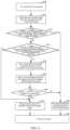
- an apparatus for correcting trapezoidal distortion of a projection plane includes: a determination unit 21 and a correction unit 22.
- the determination unit 21 is configured to: measure a trend of change in a distance between a projector and a projection plane by using a rotatable range finder, and determine a correction included angle according to the obtained trend of change.
- the correction unit 22 is configured to correct trapezoidal distortion of the projection plane according to the determined correction included angle.
- FIG. 3 illustrates a flowchart of a method for correcting trapezoidal distortion correction of a projection plane when trapezoidal distortion correction is automatic vertical trapezoidal distortion correction according to one embodiment of the present invention. As illustrated in FIG. 3 , after a projector is disposed and fixed, the method includes the following steps.
- step 100 an included angle between a projector and a horizontal plane is determined.
- the included angle between the projector and the horizontal plane is an included angle between the projector along a projection center line and the horizontal plane.
- the size of the included angle may be measured by a gyroscope.
- step 101 when the determined included angle between the projector and the horizontal plane is greater than a first included angle threshold and an included angle between an upper projection boundary of the projector and the horizontal plane is less than a second included angle threshold, a trend of change in a distance between the projector and a projection plane is measured by using a rotatable range finder, and a correction included angle is determined according to the trend of change.
- the first included angle threshold may be 45° and the second included angle threshold may be 90°.
- measuring the distance between the projector and the projection plane by using the rotatable range finder includes: measuring a first distance between a parallel direction of the projector and the projection plane and a second distance between the direction of the upper projection boundary of the projector and the projection plane by using the rotatable range finder.
- measuring the trend of change in the distance between the projector and the projection plane by using the rotatable range finder includes: if the trend of change from the first distance to the second distance is a decrease trend, indicating that the projection plane is in parallel with the horizontal plane, i.e., the projection plane is a ceiling; and if the trend of change from the first distance to the second distance is an increase trend, indicating that the projection plane is perpendicular to the horizontal plane, i.e., the projection plane is a wall.
- measuring the distance between the projector and the projection plane by using the rotatable range finder includes: measuring a second distance between the direction of the upper projection boundary of the projector and the projection plane and a third distance between the direction of a lower projection boundary of the projector and the projection plane by using the rotatable range finder.
- measuring the trend of change in the distance between the projector and the projection plane by using the rotatable range finder includes: if the second distance is less than the third distance, indicating that the projection plane is in parallel with the horizontal plane, i.e., the projection plane is a ceiling; and if the second distance is greater than the third distance, indicating that the projection plane is perpendicular to the horizontal plane, i.e., the projection plane is a wall.
- Step 101 further includes: when the determined included angle between the projector and the horizontal plane is less than the first included angle threshold, indicating that the projection plane is perpendicular to the horizontal plane, i.e., the projection plane is a wall; and when the included angle between the upper projection boundary of the projector and the horizontal plane is greater than the second included angle threshold, indicating that the projection plane is in parallel with the horizontal plane, i.e., the projection plane is a ceiling.
- step 101 determining the correction included angle according to the trend of change includes:
- step 102 trapezoidal distortion of the projection plane is corrected according to the determined correction included angle.
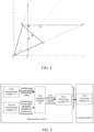
- FIG. 4 illustrates a schematic view of determining a projection plane based on the method illustrated in FIG. 3 according to an embodiment of the present invention.
- connecting line AD is a direction of a projection optical machine, i.e., the projector along a projection center line
- connecting line AB and connecting line AC are respectively projection boundaries of the projection optical machine.
- connecting line AB is an upper projection boundary
- connecting line AC is a lower projection boundary.
- Connecting line AG is a projection center line, and an included angle between the direction AD of the projection optical machine and the horizontal plane AI is 74°.
- a rotation angle range of a rotatable range finder is an angle range of the upper and lower projection boundaries of the projector, i.e., angle BAC.
- dual range finders may also be used to simultaneously measure a distance from the projector to the upper projection boundary and a distance from the projector to the lower projection boundary, i.e., simultaneously measure the distance in direction AB and the distance in direction AF.
- the rotatable range finder scans the distance from the direction AD of the projection optical machine to the upper projection boundary AB. From FIG. 4 , it can be seen that the distance AG between the direction AD of the projector and the ceiling BF is longer than the distance AB between the projector and the ceiling BF. As long as the projection optical machine exceeds 45° and the included angle between the upper projection boundary AB and the horizontal plane is less than 90°, only at this moment the projector possibly has two situations, i.e., the projection plane may be a ceiling and the projection plane may also be a wall surface.
- the included angle between the distance AB and the horizontal plane exceeds 90° and is less than 180°, the situation that the projection plane is the wall surface does not possibly exist and thus the situation that the angle ABF is an obtuse angle is the only case.
- an opposite side (AG) of an obtuse angle (ABG) of an obtuse triangle (AGB) is greater than any other side (AB)
- the range finder scans the distance from the direction of the optical machine to an acute angle perpendicular to a horizontal direction; and if the distance is in a decrease trend, the projection plane is the ceiling.
- the rotatable range finder scans the distance from the direction AD of the projection optical machine to the direction of the upper projection boundary AB. From FIG. 4 , it can be seen that the distance AK between the projector and the wall surface is less than the distance between the projector and the projection boundary AE. According to the theorem, it can be seen that a side (AF) opposite an obtuse angle (AKE) of an obtuse triangle (AEK) is greater than any other side (AK) and this is unrelated to the distance between the projector and the wall surface. As long as the included angle between the projection optical machine and the horizontal plane is greater than 0°, AKE is always an obtuse angle.
- FIG. 5 illustrates a structural schematic diagram of an apparatus for correcting trapezoidal distortion of a projection plane according to FIG. 2 .
- the determination unit 21 includes: a first measurement module 211, a second measurement module 212, a first judgment module 213 and a first processing module 214; and the correction unit 22 includes: a first correction module 221.
- the first measurement module 211 is configured to: determine an included angle between the projector and a horizontal plane, and output the included angle to the first judgment module 214. After the position of the projector is fixed, the included angle may be measured by a gyroscope.
- the second measurement module 212 is configured to: determine an included angle between an upper projection boundary of the projector and the horizontal plane, and output the included angle to the first judgment module 214.
- the included angle may be measured by the gyroscope.
- the first judgment module 213 is configured to: determine that the projection plane is the wall if the projection plane is perpendicular to the horizontal plane, or is a ceiling if the projection plane is in parallel with the horizontal plane, according to the included angle between the projector and the horizontal plane coming from the first measurement module 211, the included angle between the upper projection boundary of the projector and the horizontal plane coming from the second measurement module 212 and the trend of change in the distance between the projector and the projection plane.
- the first judgment module 213 is configured to: when the included angle between the projector and the horizontal plane is greater than a first included angle threshold and the included angle between the upper projection boundary of the projector and the horizontal plane is less than a second included angle threshold, measure the trend of change in the distance between the projector and the projection plane by using the rotatable range finder, and output a first notification or a second notification to the first processing module 214 according to the trend of change.
- the distance between the projector and the projection plane measured by the rotatable range finder includes a first distance between a parallel direction of the projector and the projection plane measured by the rotatable range finder and a second distance between the direction of the upper projection boundary of the projector and the projection plane measured by the rotatable range finder
- the trend of change from the first distance to the second distance is a decrease trend
- the projection plane is in parallel with the horizontal plane, i.e., the projection plane is a ceiling and a second notification is sent to the first processing module 214
- the trend of change from the first distance to the second distance is an increase trend
- the projection plane is perpendicular to the horizontal plane, i.e., the projection plane is a wall, and a first notification is sent to the first processing module 214.
- the distance between the projector and the projection plane measured by the rotatable range finder includes: a second distance between the direction of the upper projection boundary of the projector and the projection plane measured by the rotatable range finder and a third distance between the direction of a lower projection boundary of the projector and the projection plane measured by the rotatable range finder, if the second distance is less than the third distance, it is indicated that the projection plane is in parallel with the horizontal plane, i.e., the projection plane is a ceiling, and a second notification is sent to the first processing module 214; and if the second distance is greater than the third distance, it is indicated that the projection plane is perpendicular to the horizontal plane, i.e., the projection plane is a wall, and a first notification is sent to the first processing module 214.
- the first judgment module 213 is further configured to:
- the first processing module 214 is configured to: when the first notification is received, determine that the correction included angle is an included angle between the projector along a projection center line and the horizontal plane; and when the second notification is received, determine that the correction included angle is an included angle between the projector along a projection center line and a wall surface, and output the determined correction included angle to the first correction module 221.
- the first correction module 221 is configured to: correct trapezoidal distortion according to the determined correction included angle.
- FIG. 6 illustrates a flowchart of one embodiment based on the method illustrated in FIG. 3 according to an embodiment of the present invention.
- a preset first included angle threshold is 45° and a preset second included angle threshold is 90°.
- the process includes the following steps.
- step 400 a position of a projector is fixed, i.e., a projector detects that the position does not change any longer.
- a gyroscope determines an included angle between the projector and a horizontal plane.
- step 402 whether the included angle between the projector (i.e., a parallel direction of a projection optical machine, also i.e., a projection center line of a projection optical machine) and the horizontal plane is less than a preset first included angle threshold, i.e., 45°, is judged, if the included angle is less than 45°, step 408 is executed; and otherwise, step 403 is executed.
- a preset first included angle threshold i.e. 45°
- step 403 whether an included angle between an upper projection boundary of the projector and the horizontal plane is greater than 90° is judged, if the included angle is greater than 90°, a situation that a projection plane is perpendicular to the horizontal plane does not exist and step 407 is executed; and otherwise, step 404 is executed.
- step 404 at this moment, the included angle between the projection center line of the projection optical machine and the horizontal direction is greater than 45° and the included angle between the upper projection boundary and the horizontal plane is less than 90°, a rotatable range finder scans and stores a first distance between the projector in the parallel direction of the projection optical machine and the projection plane.
- step 405 the rotatable range finder scans and stores a second distance between the projector and the projection plane from the direction of the upper projection boundary of the projector.
- step 406 whether a trend of change from the first distance to the second distance is a decrease trend is judged, if yes, step 407 is executed; and if not, step 408 is executed.
- This step may also be as follow: when it is directly judged that the distance between the upper projection boundary of the projector and the projection plane is less than the distance between a lower projection boundary of the projector and the projection plane, step 407 is executed; and when it is directly judged that the distance between the upper projection boundary of the projector and the projection plane is greater than the distance between the lower projection boundary of the projector and the projection plane, step 408 is executed.
- step 407 it is judged that the projection plane is in parallel with the horizontal plane, i.e., the projection plane is a ceiling.
- a correction included angle i.e., the included angle between the projector and the projection plane, is the included angle between the projector along the projection center line and the horizontal plane, and step 409 is executed.
- step 408 it is judged that the projection plane is perpendicular to the horizontal plane, i.e., the projection plane is a wall.
- the correction included angle i.e., the included angle between the projector and the projection plane, is the included angle between the projector along the projection center line and a wall surface.
- step 409 an image is corrected according to the obtained correction included angle, i.e., the included angle between the projector and the projection plane, and the corrected image is output by the projection optical machine.
- FIG. 7 illustrates a flowchart of another method for correcting trapezoidal distortion of a projection plane according to an embodiment of the present invention. As illustrated in FIG. 7 , the method includes the following steps.
- step 500 scanning is performed from the direction of any projection boundary to the direction of another projection boundary of a projector to obtain multiple distances between the projector and a projection plane.
- the distances between the projector and the projection plane may be obtained by scanning in a projection range of the projector through a front rotatable range finder of the projector.
- distance values may be acquired according to a preset sampling period; and distance values at corresponding positions may also be acquired according to a preset fixed sampling number, as long as a trend of change of the obtained distance values in the projection range can be obtained.
- the sampling period may be determined according to the distance between the projector and the projection plane, the greater the distance is, the shorter the sampling period is, and the less the distance is, the longer the sampling period is.
- a correction included angle is an included angle between the projector along a projection center line and the direction of the shortest distance, i.e., an actual included angle between the projector on a horizontal plane and the projection plane.
- the correction included angle may be measured by a rotation angle sensor. It is emphasized here that the correction included angle is determined as an actual included angle between the projector on the horizontal plane and the projection plane only when there is a trend of changing from great to small and then changing from small to great.
- this step further includes: It is to scan from the direction of the projection center line of the projector to a rear of the projector through a side rotatable range finder of the projector to obtain multiple distances between the projector and the projection plane, so as to determine the shortest distance between the projector and the projection plane.
- a cosine value of the correction included angle is a ratio of the determined shortest distance to the distance between the projector along the projection center line and the projection plane.
- step 502 trapezoidal distortion is corrected according to the determined correction included angle.
- FIG. 8(a) illustrates a schematic view of embodiment 1 for determining the shortest distance based on the method illustrated in FIG. 7 according to the present invention.
- the shortest distance exists in a projection range.
- connecting line DE is a projection center line and is located between left projection boundary AD and right projection boundary CD, and there is a shortest distance, i.e., connecting line BD.
- connecting line BD is a perpendicular distance from a projector to a projection plane, and at this moment angle EDB may be determined by a rotation angle sensor.
- FIG. 8(b) illustrates a schematic view of embodiment 2 for determining the shortest distance based on the method illustrated in FIG. 7 according to the present invention.
- an angle between the projector and the projection plane on the horizontal plane is too large.
- the shortest distance in the projection range is connecting line KG, however connecting line KG is not a perpendicular distance between the projector and the projection plane.
- a rotatable range finder on a left side of the projector needs to be started to scan the distance from the direction of the projection optical machine to the rear of the projector to obtain the shortest distance FJ.
- a cosine value of angle FJG is obtained, i.e., FJ/GJ.
- FIG.8(a) and FIG. 8(b) are two schematic views which illustrate the situation that the left side of the projector is close to the projection plane.
- the principle for the situation that the right side is close to the projection plane is the same as that of the situation that the left side is close to the projection plane and thus is not repetitively described here.
- FIG. 9 illustrates a structural schematic diagram of components of another apparatus for correcting trapezoidal distortion of a projection plane according to FIG. 2 .
- the determination unit 21 includes: a first scanning module 215, a second judgment module 216 and a second processing module 217; and the correction unit 22 includes: a second correction module 222.
- the first scanning module 215 is configured to: scan from the direction of any projection boundary to the direction of another projection boundary of the projector to obtain multiple distances between the projector and the projection plane, and output the multiple distances to the second judgment module 216.
- the second judgment module 216 is configured to: determine that the multiple distances obtained through scanning have a trend of changing from great to small and then changing from small to great, and send a third notification to the second processing module 217.
- the second processing module 217 is configured to: when the third notification is received, determine that the correction included angle is an included angle between the projector along a projection center line and the direction of the shortest distance, i.e., an actual included angle between the projection on the horizontal plane and the projection plane; and output the correction included angle to the second correction module 222.
- the second correction module 222 is configured to: correct trapezoidal distortion according to the determined correction included angle.
- the apparatus illustrated in FIG. 9 further includes a second scanning module 218; at this moment,
- the apparatusillustrated in FIG. 2 , the apparatus illustrated in FIG. 6 and/or the apparatus illustrated in FIG. 9 according to the embodiment of the present invention are arranged in the projector.
- FIG. 10 illustrates a flowchart of one embodiment based on the method illustrated in FIG. 7 according to the present invention. As illustrated in FIG. 10 , the process includes the following steps.
- step 800 a position of a projector is fixed, i.e., i.e., a projector detects that a position does not change any longer at this moment.
- a front rotatable range finder of the projector starts to scan distances to a wall surface in a projection range from any projection boundary to obtain multiple distance values.
- step 802 whether the scanned distances have a trend of changing from great to small and then changing from small to great in the projection range is judged, if yes, step 806 is executed; and if not, step 803 is executed.
- a side rotatable range finder starts to scan distances from one projection boundary with a shorter distance to a projection plane to a rear of the projector, i.e., scan side distances.
- step 804 the shortest distance between the side of the projector and the projection plane, i.e., perpendicular distance, is obtained through scanning.
- step 805 a correction included angle, i.e., an included angle between the projector on a horizontal plane and the projection plane, is obtained according to cosine theorem.
- a cosine value of the correction included angle is a ratio of the determined shortest distance to the distance between the projector along a projection center line and the projection plane.
- step 806 an included angle between the direction of the projection center line and the direction of the shortest distance is determined by a rotation angle sensor, i.e., a correction included angle is obtained, and then step 807 is executed.
- step 807 an image is corrected according to the obtained correction included angle, i.e., an included angle between the projector and the projection plane, and the corrected image is output by a projection optical machine.
- all or partial steps in the above-mentioned embodiments may also be implemented by using integrated circuits, and these steps may be respectively manufactured into individual integrated circuit modules, or more modules or steps thereof may be manufactured into a single integrated circuit module to implement.
- Each device/function module/function unit in the above-mentioned embodiments may be implemented by using a general-purpose computing device, and they may be integrated on a single computing device and may also be distributed on a network consisting of multiple computing devices.
- devices/function modules/function units in the above-mentioned embodiments are implemented by means of software function module and are sold or used as an independent product, they may be stored in a computer-readable storage medium.
- the above-mentioned computer-readable storage medium may be a read-only memory, a magnetic disk, a compact disk or the like.
- trapezoidal distortion correction can be automatically and accurately realized.
- the embodiments of the present invention not only can realize automatic vertical trapezoidal distortion correction, but also can realize automatic horizontal trapezoidal distortion correction. As compared with the related art, the user experience is better.
Landscapes
- Physics & Mathematics (AREA)
- Engineering & Computer Science (AREA)
- Multimedia (AREA)
- Signal Processing (AREA)
- General Physics & Mathematics (AREA)
- Geometry (AREA)
- Optics & Photonics (AREA)
- Projection Apparatus (AREA)
- Transforming Electric Information Into Light Information (AREA)
Claims (12)
- Verfahren zum Korrigieren einer trapezförmigen Verzerrung einer Projektionsebene, umfassend:Bestimmen (100) eines eingeschlossenen Winkels zwischen einem Projektor und einer horizontalen Ebene und eines eingeschlossenen Winkels zwischen einer oberen Projektionsgrenze des Projektors und der horizontalen Ebene, Messen, wenn der eingeschlossene Winkel zwischen dem Projektor und der horizontalen Ebene größer als ein voreingestellter erster Schwellenwert des eingeschlossenen Winkels ist und der eingeschlossene Winkel zwischen der oberen Projektionsgrenze des Projektors und der horizontalen Ebene kleiner als ein voreingestellter zweiter Schwellenwert des eingeschlossenen Winkels ist, einer Tendenz zur Änderung eines Abstands zwischen dem Projektor und einer Projektionsebene durch Verwenden eines drehbaren Entfernungsmessers,Bestimmen einer Beziehung zwischen der Projektionsebene und der horizontalen Ebene gemäß der erhaltenen Tendenz zur Änderung, die Beziehung umfassend, dass die Projektionsebene zu der horizontalen Ebene senkrecht oder parallel ist, undBestimmen einer Korrektur des eingeschlossenen Winkels gemäß der Beziehung; undKorrigieren (102) der trapezförmigen Verzerrung der Projektionsebene gemäß der bestimmten Korrektur des eingeschlossenen Winkels.
- Verfahren nach Anspruch 1, wobei:
das Messen des Abstands zwischen dem Projektor und der Projektionsebene durch Verwenden des drehbaren Entfernungsmessers umfasst: Messen (404; 405) eines ersten Abstands zwischen einer parallelen Richtung des Projektors und der Projektionsebene und eines zweiten Abstands zwischen einer Richtung der oberen Projektionsgrenze des Projektors und der Projektionsebene durch Verwenden des drehbaren Entfernungsmessers. - Verfahren nach Anspruch 2, wobei das Messen der Tendenz zur Änderung des Abstands zwischen dem Projektor und der Projektionsebene durch Verwenden des drehbaren Entfernungsmessers umfasst:wenn die Tendenz zur Änderung von dem ersten Abstand zu dem zweiten Abstand eine abnehmende Tendenz ist, Bestimmen (407), dass die Projektionsebene zu der horizontalen Ebene parallel ist; undwenn die Tendenz zur Änderung von dem ersten Abstand zu dem zweiten Abstand eine zunehmende Tendenz ist, Bestimmen (408), dass die Projektionsebene zu der horizontalen Ebene senkrecht ist.
- Verfahren nach Anspruch 1, wobei das Messen des Abstands zwischen dem Projektor und der Projektionsebene durch Verwenden des drehbaren Entfernungsmessers umfasst: Messen des zweiten Abstands zwischen der Richtung der oberen Projektionsgrenze des Projektors und der Projektionsebene und eines dritten Abstands zwischen einer Richtung einer unteren Projektionsgrenze des Projektors und der Projektionsebene.
- Verfahren nach Anspruch 4, wobei das Messen der Tendenz zur Änderung des Abstands zwischen dem Projektor und der Projektionsebene durch Verwenden des drehbaren Entfernungsmessers umfasst:wenn der zweite Abstand kleiner als der dritte Abstand ist, Bestimmen, dass die Projektionsebene zu der horizontalen Ebene parallel ist; undwenn der zweite Abstand größer als der dritte Abstand ist, Bestimmen, dass die Projektionsebene zu der horizontalen Ebene senkrecht ist.
- Verfahren nach Anspruch 1, wobei das Verfahren ferner umfasst:wenn der bestimmte eingeschlossene Winkel zwischen dem Projektor und der horizontalen Ebene kleiner als der erste Schwellenwert des eingeschlossenen Winkels ist, Bestimmen, dass die Projektionsebene zu der horizontalen Ebene senkrecht ist; undwenn der eingeschlossene Winkel zwischen der oberen Projektionsgrenze des Projektors und der horizontalen Ebene größer als der zweite Schwellenwert des eingeschlossenen Winkels ist, Bestimmen, dass die Projektionsebene zu der horizontalen Ebene parallel ist.
- Verfahren nach einem der Ansprüche 3, 5 oder 6, wobei das Bestimmen der Korrektur des eingeschlossenen Winkels gemäß der Tendenz zur Änderung umfasst:wenn die Projektionsebene zu der horizontalen Ebene parallel ist, Bestimmen, dass die Korrektur des eingeschlossenen Winkels ein eingeschlossener Winkel zwischen dem Projektor entlang einer Projektionsmittellinie und der horizontalen Ebene ist; undwenn die Projektionsebene zu der horizontalen Ebene senkrecht ist, Bestimmen, dass die Korrektur des eingeschlossenen Winkels ein eingeschlossener Winkel zwischen dem Projektor entlang einer Projektionsmittellinie und der Projektionsebene ist.
- Verfahren zum Korrigieren einer trapezförmigen Verzerrung einer Projektionsebene, umfassend: Messen einer Tendenz zur Änderung eines Abstands zwischen einem Projektor und einer Projektionsebene durch Verwenden eines drehbaren Entfernungsmessers, wenn bestimmt wird, dass ein eingeschlossener Winkel zwischen einem Projektor und einer horizontalen Ebene größer als ein voreingestellter erster Schwellenwert für den eingeschlossenen Winkel ist und ein eingeschlossener Winkel zwischen einer oberen Projektionsgrenze des Projektors und der horizontalen Ebene kleiner als ein voreingestellter zweiter Schwellenwert für den eingeschlossenen Winkel ist, und Bestimmen einer Korrektur des eingeschlossenen Winkels gemäß der erhaltenen Tendenz zur Änderung; undKorrigieren der trapezförmigen Verzerrung der Projektionsebene gemäß der bestimmten Korrektur des eingeschlossenen Winkels;wobei das Messen des Abstands zwischen dem Projektor und der Projektionsebene durch Verwenden des drehbaren Entfernungsmessers umfasst:Abtasten (500) von einer Richtung einer beliebigen Projektionsgrenze in eine Richtung einer anderen Projektionsgrenze des Projektors, um eine Vielzahl von Abständen zwischen dem Projektor und der Projektionsebene zu erhalten;wobei das Messen der Tendenz zur Änderung des Abstands zwischen dem Projektor und der Projektionsebene durch Verwenden des drehbaren Entfernungsmessers umfasst:Bestimmen (501), dass die Vielzahl der Abstände, die durch das Abtasten erhalten werden, eine Tendenz zur Änderung von groß nach klein und dann von klein nach groß aufweisen; und entsprechend,Bestimmen (501) der Korrektur des eingeschlossenen Winkels gemäß der Tendenz zur Änderung als ein eingeschlossener Winkel zwischen dem Projektor entlang einer Projektionsmittellinie und einer Richtung einer kürzesten Distanz.
- Verfahren nach Anspruch 8, wobei das Messen der Tendenz zur Änderung des Abstands zwischen dem Projektor und der Projektionsebene durch Verwenden des drehbaren Entfernungsmessers ferner umfasst: Bestimmen, dass die Vielzahl von Abständen, die durch das Abtasten erhalten werden, keine Tendenz zur Änderung von groß nach klein und dann von klein nach groß aufweisen;wobei das Verfahren ferner umfasst: Abtasten (803) aus einer Richtung der Projektionsmittellinie des Projektors zu einer Rückseite des Projektors, um eine Vielzahl von Abständen zwischen dem Projektor und der Projektionsebene zu erhalten, um einen kürzesten Abstand zwischen dem Projektor und der Projektionsebene zu bestimmen (804); und entsprechend,Bestimmen (805) der Korrektur des eingeschlossenen Winkels gemäß der Tendenz zur Änderung als eine Korrektur des eingeschlossenen Winkels, dessen Kosinuswert ein Verhältnis des kürzesten Abstands zu dem Abstand zwischen dem Projektor entlang der Projektionsmittellinie und der Projektionsebene ist.
- Vorrichtung zum Korrigieren einer trapezförmigen Verzerrung einer Projektionsebene, umfassend eine Bestimmungseinheit und eine Korrektureinheit, wobei:die Bestimmungseinheit konfiguriert ist zum: Messen einer Tendenz zur Änderung in einem Abstand zwischen einem Projektor und einer Projektionsebene durch Verwenden eines drehbaren Entfernungsmessers, wenn bestimmt wird, dass ein eingeschlossener Winkel zwischen einem Projektor und einer horizontalen Ebene größer als ein voreingestellter erster Schwellenwert des eingeschlossenen Winkels ist und ein eingeschlossener Winkel zwischen einer oberen Projektionsgrenze des Projektors und der horizontalen Ebene kleiner als ein voreingestellter zweiter Schwellenwert des eingeschlossenen Winkels ist, Bestimmen einer Beziehung zwischen der Projektionsebene und der horizontalen Ebene gemäß der erhaltenen Tendenz zur Änderung, die Beziehung umfassend, dass die Projektionsebene zu der horizontalen Ebene senkrecht oder parallel ist, und Bestimmen einer Korrektur des eingeschlossenen Winkels gemäß der Beziehung;die Korrektureinheit konfiguriert ist zum: Korrigieren der trapezförmigen Verzerrung der Projektionsebene gemäß der bestimmten Korrektur des eingeschlossenen Winkels;die Bestimmungseinheit umfasst: ein erstes Messmodul, ein zweites Messmodul, ein erstes Beurteilungsmodul und ein erstes Verarbeitungsmodul; und die Korrektureinheit umfasst: ein erstes Korrekturmodul, wobeidas erste Messmodul konfiguriert ist zum: Bestimmen des eingeschlossenen Winkels zwischen dem Projektor und der horizontalen Ebene und Ausgeben des eingeschlossenen Winkels an das erste Beurteilungsmodul;das zweite Messmodul konfiguriert ist zum: Bestimmen des eingeschlossenen Winkels zwischen der oberen Projektionsgrenze des Projektors und der horizontalen Ebene und Ausgeben des eingeschlossenen Winkels an das erste Beurteilungsmodul;das erste Beurteilungsmodul konfiguriert ist zum: Bestimmen, ob die Projektionsebene zu der horizontalen Ebene senkrecht oder zu der horizontalen Ebene parallel ist, gemäß dem eingeschlossenen Winkel zwischen dem Projektor und der horizontalen Ebene, der von dem ersten Messmodul kommt, wobei der eingeschlossene Winkel zwischen der oberen Projektionsgrenze des Projektors und der horizontalen Ebene von dem zweiten Messmodul und der Tendenz zur Änderung des Abstands zwischen dem Projektor und der Projektionsebene kommt, und Ausgeben einer ersten Benachrichtigung oder einer zweiten Benachrichtigung an das erste Verarbeitungsmodul;wobei das erste Verarbeitungsmodul konfiguriert ist zum: wenn die erste Benachrichtigung erhalten wird, Bestimmen, dass die Korrektur des eingeschlossenen Winkels ein eingeschlossener Winkel zwischen dem Projektor entlang einer Projektionsmittellinie und der horizontalen Ebene ist; und wenn die zweite Benachrichtigung empfangen wird, Bestimmen, dass die Korrektur des eingeschlossenen Winkels ein eingeschlossener Winkel zwischen dem Projektor entlang einer Projektionsmittellinie und einer Wandoberfläche ist, und Ausgeben der bestimmten Korrektur des eingeschlossenen Winkels an das erste Korrekturmodul; undwobei das erste Korrekturmodul konfiguriert ist zum: Korrigieren der trapezförmigen Verzerrung gemäß der bestimmten Korrektur des eingeschlossenen Winkels.
- Vorrichtung nach Anspruch 10, wobei die Bestimmungseinheit umfasst: ein erstes Abtastmodul, ein zweites Beurteilungsmodul und ein zweites Verarbeitungsmodul; und die Korrektureinheit umfasst: ein zweites Korrekturmodul, wobeidas erste Abtastmodul konfiguriert ist zum: Abtasten von einer Richtung einer beliebigen Projektionsgrenze in eine Richtung einer anderen Projektionsgrenze des Projektors, um eine Vielzahl von Abständen zwischen dem Projektor und der Projektionsebene zu erhalten, und Ausgeben der Vielzahl von Abständen an das zweite Beurteilungsmodul;das zweite Beurteilungsmodul konfiguriert ist zum: Bestimmen, dass die Vielzahl der Abstände, die durch das Abtasten erhalten werden, eine Tendenz zur Änderung von groß nach klein und dann von klein nach groß aufweisen, und Senden einer dritten Benachrichtigung an das zweite Verarbeitungsmodul;das zweite Verarbeitungsmodul konfiguriert ist zum: wenn die dritte Benachrichtigung erhalten wird, Bestimmen, dass die Korrektur des eingeschlossenen Winkels ein eingeschlossener Winkel zwischen dem Projektor entlang einer Projektionsmittellinie und einer Richtung einer kürzesten Distanz ist; und Ausgeben der Korrektur des eingeschlossenen Winkels an das zweite Korrekturmodul; unddas zweite Korrekturmodul konfiguriert ist zum: Korrigieren der trapezförmigen Verzerrung gemäß der bestimmten Korrektur des eingeschlossenen Winkels.
- Computerlesbares Speichermedium, das computerausführbare Anweisungen speichert, die zum Ausführen des Verfahrens nach einem der Ansprüche 1 bis 9 verwendet werden.
Applications Claiming Priority (2)
| Application Number | Priority Date | Filing Date | Title |
|---|---|---|---|
| CN201510390145.1A CN105093789B (zh) | 2015-07-03 | 2015-07-03 | 一种实现投影面梯形失真校正的方法及装置和投影仪 |
| PCT/CN2015/097913 WO2016131336A1 (zh) | 2015-07-03 | 2015-12-18 | 一种实现投影面梯形失真校正的方法及装置 |
Publications (3)
| Publication Number | Publication Date |
|---|---|
| EP3306390A1 EP3306390A1 (de) | 2018-04-11 |
| EP3306390A4 EP3306390A4 (de) | 2019-05-08 |
| EP3306390B1 true EP3306390B1 (de) | 2025-05-28 |
Family
ID=54574542
Family Applications (1)
| Application Number | Title | Priority Date | Filing Date |
|---|---|---|---|
| EP15882475.5A Active EP3306390B1 (de) | 2015-07-03 | 2015-12-18 | Verfahren und vorrichtung zur ausführung einer trapezverzerrungskorrektur einer projektionsfläche |
Country Status (4)
| Country | Link |
|---|---|
| US (1) | US10212403B2 (de) |
| EP (1) | EP3306390B1 (de) |
| CN (1) | CN105093789B (de) |
| WO (1) | WO2016131336A1 (de) |
Families Citing this family (10)
| Publication number | Priority date | Publication date | Assignee | Title |
|---|---|---|---|---|
| CN105093789B (zh) | 2015-07-03 | 2021-05-11 | 中兴通讯股份有限公司 | 一种实现投影面梯形失真校正的方法及装置和投影仪 |
| CN107613278A (zh) * | 2016-07-11 | 2018-01-19 | 中兴通讯股份有限公司 | 投影装置 |
| CN108873578B (zh) * | 2018-09-11 | 2024-06-18 | 广州市易卓交通科技有限公司 | 成像器内部可攀爬梯形结构 |
| CN110456602B (zh) * | 2019-08-22 | 2021-06-18 | 歌尔股份有限公司 | 一种投影系统的投影图案校正装置、方法及系统 |
| CN110827288B (zh) * | 2019-10-08 | 2022-08-12 | 歌尔光学科技有限公司 | 投影仪清晰度测试中目标图像的提取方法及装置 |
| JP2021071567A (ja) * | 2019-10-30 | 2021-05-06 | カシオ計算機株式会社 | 投影装置、設置状態検知方法および設置状態検知プログラム |
| CN113375601B (zh) * | 2020-02-25 | 2023-03-14 | 广东博智林机器人有限公司 | 墙体阴阳角测量方法、装置、设备及存储介质 |
| CN113869303B (zh) * | 2020-06-30 | 2024-09-17 | 北京搜狗科技发展有限公司 | 图像处理方法、装置和介质 |
| CN115086622B (zh) | 2021-03-12 | 2024-05-24 | 中强光电股份有限公司 | 投影机及其校正方法 |
| CN115273711A (zh) * | 2021-04-29 | 2022-11-01 | 中强光电股份有限公司 | 投影设备及其自动调整投影方法 |
Family Cites Families (12)
| Publication number | Priority date | Publication date | Assignee | Title |
|---|---|---|---|---|
| EP1391778A1 (de) * | 2002-08-08 | 2004-02-25 | Seiko Precision Inc. | Apparat zur Bestimmung des Neigungswinkels eines Projektionsschirmes und einen Projektor, der diesen Apparat beinhaltet |
| JP3711973B2 (ja) * | 2002-10-09 | 2005-11-02 | 株式会社日立製作所 | 投射型表示装置 |
| JP3772870B2 (ja) * | 2003-08-25 | 2006-05-10 | カシオ計算機株式会社 | 投影装置、投影方法及びプログラム |
| JP4023447B2 (ja) * | 2004-01-09 | 2007-12-19 | カシオ計算機株式会社 | 投影装置、投影方法及びプログラム |
| JP2006135675A (ja) * | 2004-11-05 | 2006-05-25 | Sanyo Electric Co Ltd | 投写型映像表示装置 |
| JP2007067495A (ja) * | 2005-08-29 | 2007-03-15 | Toshiba Corp | プロジェクタ装置 |
| JP2008033301A (ja) * | 2006-06-30 | 2008-02-14 | Pentax Corp | 画像投影表示装置の調整方法 |
| US8730130B1 (en) * | 2008-12-04 | 2014-05-20 | RPA Electronic Solutions, Inc. | System and method for automatically aligning immersive displays |
| CN102650805A (zh) * | 2012-05-25 | 2012-08-29 | 深圳市众进思创科技开发有限公司 | 一种投影仪及其多方向投影图像的校正方法 |
| CN104243879A (zh) * | 2013-06-24 | 2014-12-24 | 中兴通讯股份有限公司 | 一种用于投影终端的图像修正方法及投影终端 |
| WO2016158166A1 (ja) * | 2015-03-30 | 2016-10-06 | 株式会社メガチップス | 投影システム、プロジェクター装置、および、プログラム |
| CN105093789B (zh) * | 2015-07-03 | 2021-05-11 | 中兴通讯股份有限公司 | 一种实现投影面梯形失真校正的方法及装置和投影仪 |
-
2015
- 2015-07-03 CN CN201510390145.1A patent/CN105093789B/zh active Active
- 2015-12-18 US US15/739,992 patent/US10212403B2/en active Active
- 2015-12-18 EP EP15882475.5A patent/EP3306390B1/de active Active
- 2015-12-18 WO PCT/CN2015/097913 patent/WO2016131336A1/zh not_active Ceased
Also Published As
| Publication number | Publication date |
|---|---|
| WO2016131336A1 (zh) | 2016-08-25 |
| EP3306390A1 (de) | 2018-04-11 |
| EP3306390A4 (de) | 2019-05-08 |
| US20180192016A1 (en) | 2018-07-05 |
| CN105093789A (zh) | 2015-11-25 |
| CN105093789B (zh) | 2021-05-11 |
| US10212403B2 (en) | 2019-02-19 |
Similar Documents
| Publication | Publication Date | Title |
|---|---|---|
| US10212403B2 (en) | Method and apparatus for realizing trapezoidal distortion correction of projection plane | |
| CN112422939A (zh) | 投影设备梯形校正方法、装置、投影设备和介质 | |
| CN113824942B (zh) | 梯形校正方法、装置、投影仪及计算机可读存储介质 | |
| CN110456602B (zh) | 一种投影系统的投影图案校正装置、方法及系统 | |
| CN104062832B (zh) | 投影装置及投影方法 | |
| CN108111828B (zh) | 投影设备校正方法、装置及投影设备 | |
| CN110381302B (zh) | 一种投影系统的投影图案校正方法、装置及系统 | |
| US20180007329A1 (en) | Projection system, projector apparatus, image capturing apparatus, and projection method | |
| WO2013024705A1 (en) | Projector and control method thereof | |
| US20200193568A1 (en) | Multi-projection system, image projection method and projector | |
| EP3306919B1 (de) | Verfahren und vorrichtung zur trapezkorrektur bei einem projektionsendgerät sowie projektionsendgerät und speichermedium | |
| CN107883874B (zh) | 一种圆结构光的标定方法 | |
| Martynov et al. | Projector calibration by “inverse camera calibration” | |
| CN107197222A (zh) | 生成投影设备的校正信息的方法及装置 | |
| CN113900346B (zh) | 投影仪的自动对焦方法和投影仪 | |
| CN114760453A (zh) | 投影画面清晰度的调整方法和投影装置 | |
| CN104796651B (zh) | 一种投影图像校准方法及投影设备 | |
| KR20230039575A (ko) | 다중-카메라 시스템들에 대한 카메라 스위칭오버 제어 기술들 | |
| CN103017660A (zh) | 具投影功能的行动测量系统及其方法 | |
| TWI889159B (zh) | 投影設備姿態校正方法、裝置、電子設備及可讀取存儲媒介 | |
| US12586249B2 (en) | Processing apparatus, processing method, and storage medium for calibrating an image capture apparatus | |
| TW202132749A (zh) | 定位裝置、記錄媒體及定位方法 | |
| CN117288151A (zh) | 一种投影设备的三维姿态确定方法、装置和电子设备 | |
| JP4803972B2 (ja) | 画像投射装置 | |
| JP5179784B2 (ja) | 三次元座標測定装置及び三次元座標測定装置において実行されるプログラム |
Legal Events
| Date | Code | Title | Description |
|---|---|---|---|
| STAA | Information on the status of an ep patent application or granted ep patent |
Free format text: STATUS: THE INTERNATIONAL PUBLICATION HAS BEEN MADE |
|
| PUAI | Public reference made under article 153(3) epc to a published international application that has entered the european phase |
Free format text: ORIGINAL CODE: 0009012 |
|
| STAA | Information on the status of an ep patent application or granted ep patent |
Free format text: STATUS: REQUEST FOR EXAMINATION WAS MADE |
|
| 17P | Request for examination filed |
Effective date: 20180103 |
|
| AK | Designated contracting states |
Kind code of ref document: A1 Designated state(s): AL AT BE BG CH CY CZ DE DK EE ES FI FR GB GR HR HU IE IS IT LI LT LU LV MC MK MT NL NO PL PT RO RS SE SI SK SM TR |
|
| AX | Request for extension of the european patent |
Extension state: BA ME |
|
| DAV | Request for validation of the european patent (deleted) | ||
| DAX | Request for extension of the european patent (deleted) | ||
| A4 | Supplementary search report drawn up and despatched |
Effective date: 20190409 |
|
| RIC1 | Information provided on ipc code assigned before grant |
Ipc: H04N 5/74 20060101ALI20190403BHEP Ipc: G03B 21/14 20060101AFI20190403BHEP |
|
| STAA | Information on the status of an ep patent application or granted ep patent |
Free format text: STATUS: EXAMINATION IS IN PROGRESS |
|
| 17Q | First examination report despatched |
Effective date: 20211110 |
|
| GRAP | Despatch of communication of intention to grant a patent |
Free format text: ORIGINAL CODE: EPIDOSNIGR1 |
|
| STAA | Information on the status of an ep patent application or granted ep patent |
Free format text: STATUS: GRANT OF PATENT IS INTENDED |
|
| INTG | Intention to grant announced |
Effective date: 20250304 |
|
| RIN1 | Information on inventor provided before grant (corrected) |
Inventor name: JIANG, NAN Inventor name: LI, PENGBO Inventor name: WANG, YUCHEN |
|
| GRAS | Grant fee paid |
Free format text: ORIGINAL CODE: EPIDOSNIGR3 |
|
| GRAA | (expected) grant |
Free format text: ORIGINAL CODE: 0009210 |
|
| STAA | Information on the status of an ep patent application or granted ep patent |
Free format text: STATUS: THE PATENT HAS BEEN GRANTED |
|
| AK | Designated contracting states |
Kind code of ref document: B1 Designated state(s): AL AT BE BG CH CY CZ DE DK EE ES FI FR GB GR HR HU IE IS IT LI LT LU LV MC MK MT NL NO PL PT RO RS SE SI SK SM TR |
|
| REG | Reference to a national code |
Ref country code: GB Ref legal event code: FG4D |
|
| REG | Reference to a national code |
Ref country code: CH Ref legal event code: EP |
|
| REG | Reference to a national code |
Ref country code: IE Ref legal event code: FG4D Ref country code: DE Ref legal event code: R096 Ref document number: 602015091749 Country of ref document: DE |
|
| REG | Reference to a national code |
Ref country code: NL Ref legal event code: MP Effective date: 20250528 |
|
| PG25 | Lapsed in a contracting state [announced via postgrant information from national office to epo] |
Ref country code: ES Free format text: LAPSE BECAUSE OF FAILURE TO SUBMIT A TRANSLATION OF THE DESCRIPTION OR TO PAY THE FEE WITHIN THE PRESCRIBED TIME-LIMIT Effective date: 20250528 Ref country code: FI Free format text: LAPSE BECAUSE OF FAILURE TO SUBMIT A TRANSLATION OF THE DESCRIPTION OR TO PAY THE FEE WITHIN THE PRESCRIBED TIME-LIMIT Effective date: 20250528 |
|
| REG | Reference to a national code |
Ref country code: LT Ref legal event code: MG9D |
|
| PG25 | Lapsed in a contracting state [announced via postgrant information from national office to epo] |
Ref country code: GR Free format text: LAPSE BECAUSE OF FAILURE TO SUBMIT A TRANSLATION OF THE DESCRIPTION OR TO PAY THE FEE WITHIN THE PRESCRIBED TIME-LIMIT Effective date: 20250829 Ref country code: NO Free format text: LAPSE BECAUSE OF FAILURE TO SUBMIT A TRANSLATION OF THE DESCRIPTION OR TO PAY THE FEE WITHIN THE PRESCRIBED TIME-LIMIT Effective date: 20250828 |
|
| PG25 | Lapsed in a contracting state [announced via postgrant information from national office to epo] |
Ref country code: NL Free format text: LAPSE BECAUSE OF FAILURE TO SUBMIT A TRANSLATION OF THE DESCRIPTION OR TO PAY THE FEE WITHIN THE PRESCRIBED TIME-LIMIT Effective date: 20250528 Ref country code: PL Free format text: LAPSE BECAUSE OF FAILURE TO SUBMIT A TRANSLATION OF THE DESCRIPTION OR TO PAY THE FEE WITHIN THE PRESCRIBED TIME-LIMIT Effective date: 20250528 |
|
| PG25 | Lapsed in a contracting state [announced via postgrant information from national office to epo] |
Ref country code: BG Free format text: LAPSE BECAUSE OF FAILURE TO SUBMIT A TRANSLATION OF THE DESCRIPTION OR TO PAY THE FEE WITHIN THE PRESCRIBED TIME-LIMIT Effective date: 20250528 |
|
| PG25 | Lapsed in a contracting state [announced via postgrant information from national office to epo] |
Ref country code: HR Free format text: LAPSE BECAUSE OF FAILURE TO SUBMIT A TRANSLATION OF THE DESCRIPTION OR TO PAY THE FEE WITHIN THE PRESCRIBED TIME-LIMIT Effective date: 20250528 |
|
| PG25 | Lapsed in a contracting state [announced via postgrant information from national office to epo] |
Ref country code: RS Free format text: LAPSE BECAUSE OF FAILURE TO SUBMIT A TRANSLATION OF THE DESCRIPTION OR TO PAY THE FEE WITHIN THE PRESCRIBED TIME-LIMIT Effective date: 20250828 |
|
| PG25 | Lapsed in a contracting state [announced via postgrant information from national office to epo] |
Ref country code: IS Free format text: LAPSE BECAUSE OF FAILURE TO SUBMIT A TRANSLATION OF THE DESCRIPTION OR TO PAY THE FEE WITHIN THE PRESCRIBED TIME-LIMIT Effective date: 20250928 |
|
| PG25 | Lapsed in a contracting state [announced via postgrant information from national office to epo] |
Ref country code: LV Free format text: LAPSE BECAUSE OF FAILURE TO SUBMIT A TRANSLATION OF THE DESCRIPTION OR TO PAY THE FEE WITHIN THE PRESCRIBED TIME-LIMIT Effective date: 20250528 |
|
| REG | Reference to a national code |
Ref country code: AT Ref legal event code: MK05 Ref document number: 1798935 Country of ref document: AT Kind code of ref document: T Effective date: 20250528 |
|
| PGFP | Annual fee paid to national office [announced via postgrant information from national office to epo] |
Ref country code: DE Payment date: 20250930 Year of fee payment: 11 |
|
| PG25 | Lapsed in a contracting state [announced via postgrant information from national office to epo] |
Ref country code: AT Free format text: LAPSE BECAUSE OF FAILURE TO SUBMIT A TRANSLATION OF THE DESCRIPTION OR TO PAY THE FEE WITHIN THE PRESCRIBED TIME-LIMIT Effective date: 20250528 Ref country code: SM Free format text: LAPSE BECAUSE OF FAILURE TO SUBMIT A TRANSLATION OF THE DESCRIPTION OR TO PAY THE FEE WITHIN THE PRESCRIBED TIME-LIMIT Effective date: 20250528 Ref country code: DK Free format text: LAPSE BECAUSE OF FAILURE TO SUBMIT A TRANSLATION OF THE DESCRIPTION OR TO PAY THE FEE WITHIN THE PRESCRIBED TIME-LIMIT Effective date: 20250528 |
|
| PG25 | Lapsed in a contracting state [announced via postgrant information from national office to epo] |
Ref country code: CZ Free format text: LAPSE BECAUSE OF FAILURE TO SUBMIT A TRANSLATION OF THE DESCRIPTION OR TO PAY THE FEE WITHIN THE PRESCRIBED TIME-LIMIT Effective date: 20250528 |
|
| PG25 | Lapsed in a contracting state [announced via postgrant information from national office to epo] |
Ref country code: EE Free format text: LAPSE BECAUSE OF FAILURE TO SUBMIT A TRANSLATION OF THE DESCRIPTION OR TO PAY THE FEE WITHIN THE PRESCRIBED TIME-LIMIT Effective date: 20250528 |
|
| PG25 | Lapsed in a contracting state [announced via postgrant information from national office to epo] |
Ref country code: SK Free format text: LAPSE BECAUSE OF FAILURE TO SUBMIT A TRANSLATION OF THE DESCRIPTION OR TO PAY THE FEE WITHIN THE PRESCRIBED TIME-LIMIT Effective date: 20250528 Ref country code: RO Free format text: LAPSE BECAUSE OF FAILURE TO SUBMIT A TRANSLATION OF THE DESCRIPTION OR TO PAY THE FEE WITHIN THE PRESCRIBED TIME-LIMIT Effective date: 20250528 |
|
| PG25 | Lapsed in a contracting state [announced via postgrant information from national office to epo] |
Ref country code: IT Free format text: LAPSE BECAUSE OF FAILURE TO SUBMIT A TRANSLATION OF THE DESCRIPTION OR TO PAY THE FEE WITHIN THE PRESCRIBED TIME-LIMIT Effective date: 20250528 |
|
| REG | Reference to a national code |
Ref country code: DE Ref legal event code: R097 Ref document number: 602015091749 Country of ref document: DE |
|
| PLBE | No opposition filed within time limit |
Free format text: ORIGINAL CODE: 0009261 |
|
| STAA | Information on the status of an ep patent application or granted ep patent |
Free format text: STATUS: NO OPPOSITION FILED WITHIN TIME LIMIT |
|
| REG | Reference to a national code |
Ref country code: CH Ref legal event code: L10 Free format text: ST27 STATUS EVENT CODE: U-0-0-L10-L00 (AS PROVIDED BY THE NATIONAL OFFICE) Effective date: 20260409 |
|
| 26N | No opposition filed |
Effective date: 20260303 |