EP3304520B1 - Alerte d'accidents prédits entre des véhicules sans conducteur - Google Patents
Alerte d'accidents prédits entre des véhicules sans conducteur Download PDFInfo
- Publication number
- EP3304520B1 EP3304520B1 EP16799462.3A EP16799462A EP3304520B1 EP 3304520 B1 EP3304520 B1 EP 3304520B1 EP 16799462 A EP16799462 A EP 16799462A EP 3304520 B1 EP3304520 B1 EP 3304520B1
- Authority
- EP
- European Patent Office
- Prior art keywords
- vehicle
- accident
- motor
- alert
- prediction
- Prior art date
- Legal status (The legal status is an assumption and is not a legal conclusion. Google has not performed a legal analysis and makes no representation as to the accuracy of the status listed.)
- Active
Links
- 206010039203 Road traffic accident Diseases 0.000 claims description 65
- 238000000034 method Methods 0.000 claims description 49
- 230000009471 action Effects 0.000 claims description 35
- 230000004044 response Effects 0.000 claims description 28
- 230000005855 radiation Effects 0.000 claims description 27
- 230000000007 visual effect Effects 0.000 claims description 16
- 238000012545 processing Methods 0.000 claims description 6
- 238000011156 evaluation Methods 0.000 claims description 3
- 230000001133 acceleration Effects 0.000 description 7
- 238000004891 communication Methods 0.000 description 7
- 230000008901 benefit Effects 0.000 description 6
- 230000005540 biological transmission Effects 0.000 description 4
- 230000008569 process Effects 0.000 description 3
- 230000001960 triggered effect Effects 0.000 description 3
- 238000013459 approach Methods 0.000 description 2
- 230000008859 change Effects 0.000 description 2
- 230000000881 depressing effect Effects 0.000 description 2
- 239000000446 fuel Substances 0.000 description 2
- 238000012986 modification Methods 0.000 description 2
- 230000004048 modification Effects 0.000 description 2
- 238000001429 visible spectrum Methods 0.000 description 2
- 206010041349 Somnolence Diseases 0.000 description 1
- 240000008042 Zea mays Species 0.000 description 1
- 235000005824 Zea mays ssp. parviglumis Nutrition 0.000 description 1
- 235000002017 Zea mays subsp mays Nutrition 0.000 description 1
- 238000013528 artificial neural network Methods 0.000 description 1
- 239000010426 asphalt Substances 0.000 description 1
- 230000000903 blocking effect Effects 0.000 description 1
- 238000002485 combustion reaction Methods 0.000 description 1
- 235000005822 corn Nutrition 0.000 description 1
- 230000007423 decrease Effects 0.000 description 1
- 230000001419 dependent effect Effects 0.000 description 1
- 230000000994 depressogenic effect Effects 0.000 description 1
- 238000010586 diagram Methods 0.000 description 1
- 230000000694 effects Effects 0.000 description 1
- 230000005670 electromagnetic radiation Effects 0.000 description 1
- 238000002474 experimental method Methods 0.000 description 1
- 238000010801 machine learning Methods 0.000 description 1
- 230000003287 optical effect Effects 0.000 description 1
- 238000001556 precipitation Methods 0.000 description 1
- 238000011160 research Methods 0.000 description 1
- 238000001228 spectrum Methods 0.000 description 1
- 230000007480 spreading Effects 0.000 description 1
- 238000012546 transfer Methods 0.000 description 1
Images


Classifications
-
- B—PERFORMING OPERATIONS; TRANSPORTING
- B60—VEHICLES IN GENERAL
- B60W—CONJOINT CONTROL OF VEHICLE SUB-UNITS OF DIFFERENT TYPE OR DIFFERENT FUNCTION; CONTROL SYSTEMS SPECIALLY ADAPTED FOR HYBRID VEHICLES; ROAD VEHICLE DRIVE CONTROL SYSTEMS FOR PURPOSES NOT RELATED TO THE CONTROL OF A PARTICULAR SUB-UNIT
- B60W30/00—Purposes of road vehicle drive control systems not related to the control of a particular sub-unit, e.g. of systems using conjoint control of vehicle sub-units, or advanced driver assistance systems for ensuring comfort, stability and safety or drive control systems for propelling or retarding the vehicle
- B60W30/08—Active safety systems predicting or avoiding probable or impending collision or attempting to minimise its consequences
- B60W30/09—Taking automatic action to avoid collision, e.g. braking and steering
-
- B—PERFORMING OPERATIONS; TRANSPORTING
- B60—VEHICLES IN GENERAL
- B60W—CONJOINT CONTROL OF VEHICLE SUB-UNITS OF DIFFERENT TYPE OR DIFFERENT FUNCTION; CONTROL SYSTEMS SPECIALLY ADAPTED FOR HYBRID VEHICLES; ROAD VEHICLE DRIVE CONTROL SYSTEMS FOR PURPOSES NOT RELATED TO THE CONTROL OF A PARTICULAR SUB-UNIT
- B60W30/00—Purposes of road vehicle drive control systems not related to the control of a particular sub-unit, e.g. of systems using conjoint control of vehicle sub-units, or advanced driver assistance systems for ensuring comfort, stability and safety or drive control systems for propelling or retarding the vehicle
- B60W30/08—Active safety systems predicting or avoiding probable or impending collision or attempting to minimise its consequences
- B60W30/085—Taking automatic action to adjust vehicle attitude in preparation for collision, e.g. braking for nose dropping
-
- B—PERFORMING OPERATIONS; TRANSPORTING
- B60—VEHICLES IN GENERAL
- B60W—CONJOINT CONTROL OF VEHICLE SUB-UNITS OF DIFFERENT TYPE OR DIFFERENT FUNCTION; CONTROL SYSTEMS SPECIALLY ADAPTED FOR HYBRID VEHICLES; ROAD VEHICLE DRIVE CONTROL SYSTEMS FOR PURPOSES NOT RELATED TO THE CONTROL OF A PARTICULAR SUB-UNIT
- B60W30/00—Purposes of road vehicle drive control systems not related to the control of a particular sub-unit, e.g. of systems using conjoint control of vehicle sub-units, or advanced driver assistance systems for ensuring comfort, stability and safety or drive control systems for propelling or retarding the vehicle
- B60W30/08—Active safety systems predicting or avoiding probable or impending collision or attempting to minimise its consequences
- B60W30/095—Predicting travel path or likelihood of collision
-
- G—PHYSICS
- G05—CONTROLLING; REGULATING
- G05D—SYSTEMS FOR CONTROLLING OR REGULATING NON-ELECTRIC VARIABLES
- G05D1/00—Control of position, course or altitude of land, water, air, or space vehicles, e.g. automatic pilot
- G05D1/02—Control of position or course in two dimensions
- G05D1/021—Control of position or course in two dimensions specially adapted to land vehicles
- G05D1/0276—Control of position or course in two dimensions specially adapted to land vehicles using signals provided by a source external to the vehicle
-
- G—PHYSICS
- G08—SIGNALLING
- G08G—TRAFFIC CONTROL SYSTEMS
- G08G1/00—Traffic control systems for road vehicles
- G08G1/16—Anti-collision systems
-
- G—PHYSICS
- G08—SIGNALLING
- G08G—TRAFFIC CONTROL SYSTEMS
- G08G1/00—Traffic control systems for road vehicles
- G08G1/16—Anti-collision systems
- G08G1/161—Decentralised systems, e.g. inter-vehicle communication
-
- G—PHYSICS
- G08—SIGNALLING
- G08G—TRAFFIC CONTROL SYSTEMS
- G08G1/00—Traffic control systems for road vehicles
- G08G1/16—Anti-collision systems
- G08G1/161—Decentralised systems, e.g. inter-vehicle communication
- G08G1/162—Decentralised systems, e.g. inter-vehicle communication event-triggered
-
- B—PERFORMING OPERATIONS; TRANSPORTING
- B60—VEHICLES IN GENERAL
- B60W—CONJOINT CONTROL OF VEHICLE SUB-UNITS OF DIFFERENT TYPE OR DIFFERENT FUNCTION; CONTROL SYSTEMS SPECIALLY ADAPTED FOR HYBRID VEHICLES; ROAD VEHICLE DRIVE CONTROL SYSTEMS FOR PURPOSES NOT RELATED TO THE CONTROL OF A PARTICULAR SUB-UNIT
- B60W2556/00—Input parameters relating to data
- B60W2556/45—External transmission of data to or from the vehicle
- B60W2556/65—Data transmitted between vehicles
-
- B—PERFORMING OPERATIONS; TRANSPORTING
- B60—VEHICLES IN GENERAL
- B60W—CONJOINT CONTROL OF VEHICLE SUB-UNITS OF DIFFERENT TYPE OR DIFFERENT FUNCTION; CONTROL SYSTEMS SPECIALLY ADAPTED FOR HYBRID VEHICLES; ROAD VEHICLE DRIVE CONTROL SYSTEMS FOR PURPOSES NOT RELATED TO THE CONTROL OF A PARTICULAR SUB-UNIT
- B60W2710/00—Output or target parameters relating to a particular sub-units
- B60W2710/18—Braking system
- B60W2710/182—Brake pressure, e.g. of fluid or between pad and disc
-
- B—PERFORMING OPERATIONS; TRANSPORTING
- B60—VEHICLES IN GENERAL
- B60W—CONJOINT CONTROL OF VEHICLE SUB-UNITS OF DIFFERENT TYPE OR DIFFERENT FUNCTION; CONTROL SYSTEMS SPECIALLY ADAPTED FOR HYBRID VEHICLES; ROAD VEHICLE DRIVE CONTROL SYSTEMS FOR PURPOSES NOT RELATED TO THE CONTROL OF A PARTICULAR SUB-UNIT
- B60W2710/00—Output or target parameters relating to a particular sub-units
- B60W2710/20—Steering systems
-
- B—PERFORMING OPERATIONS; TRANSPORTING
- B60—VEHICLES IN GENERAL
- B60W—CONJOINT CONTROL OF VEHICLE SUB-UNITS OF DIFFERENT TYPE OR DIFFERENT FUNCTION; CONTROL SYSTEMS SPECIALLY ADAPTED FOR HYBRID VEHICLES; ROAD VEHICLE DRIVE CONTROL SYSTEMS FOR PURPOSES NOT RELATED TO THE CONTROL OF A PARTICULAR SUB-UNIT
- B60W2720/00—Output or target parameters relating to overall vehicle dynamics
- B60W2720/10—Longitudinal speed
- B60W2720/106—Longitudinal acceleration
-
- B—PERFORMING OPERATIONS; TRANSPORTING
- B60—VEHICLES IN GENERAL
- B60W—CONJOINT CONTROL OF VEHICLE SUB-UNITS OF DIFFERENT TYPE OR DIFFERENT FUNCTION; CONTROL SYSTEMS SPECIALLY ADAPTED FOR HYBRID VEHICLES; ROAD VEHICLE DRIVE CONTROL SYSTEMS FOR PURPOSES NOT RELATED TO THE CONTROL OF A PARTICULAR SUB-UNIT
- B60W2756/00—Output or target parameters relating to data
- B60W2756/10—Involving external transmission of data to or from the vehicle
Definitions
- a driverless vehicle also known as “autonomous vehicle”, “self-driving vehicle” and “robotic vehicle” is a vehicle that is capable of sensing its environment and navigating without human input.
- driverless cars were predicted by many science fiction and non-science fiction writers a long time ago. In recent years, this idea has been actualized, with many auto makers and research groups building such cars and conducting experiments with them. Publications about self-driving cars include (i) " INSIDE GOOGLE'S QUEST TO POPULARIZE SELF-DRIVING CARS," By Adam Fisher, Popular Science (Posted September 18, 2013 ) about Google's driverless car, and (ii) " NASA AND NISSAN JOIN FORCES TO BUILD SELF-DRIVING VEHICLES FOR EARTH AND SPACE” by Alex Davies, Wired, corn (Posted January 8, 2015 ) about Nissan's and NASA's driverless car.
- driverless or autonomous motor-vehicles also includes semi-autonomous vehicles where a human driver may be available inside the motor-vehicle and may intervene with or take control of the driving if he so decides, as long as the motor-vehicle has a fully autonomous mode in which it navigates and drives without human input.
- driverless cars Obviously, a major concern with driverless cars is the avoidance of accidents where two or more cars are involved in a collision. The challenge is especially difficult under heavy traffic conditions, when many cars are driving in a convoy, continuously braking, decelerating and accelerating according to traffic events and road conditions.
- First attempts for developing a driverless car relied on equipping the car with sensors capable of detecting events in all directions.
- front-looking cameras and proximity sensors residing within a given car may monitor the car in front of it, looking for an indication it is braking or otherwise slowing down. If such an event is detected, and there is a danger of the given car hitting the car in front of it, the driving logic automatically slows down the given car or even brings it to a complete stop.
- rearward-looking cameras and proximity sensors are watching the car behind the given car, looking for an indication it is accelerating. If such an event is detected, and there is a danger of the given car being hit by the car behind it, the driving logic automatically accelerates the given car or otherwise maneuvers it to avoid being hit.
- Additional cameras and sensors may be directed sideways so as to watch for potential dangers from other directions.
- each car wirelessly transmit information about itself so that adjacent cars can receive that information and use it for taking their decisions. For example, when a driver starts to press down on his braking pedal the car immediately reports this event by transmitting a braking alert, without waiting for the braking process to actually slow down the car.
- the car immediately behind the braking car does not have to wait until its sensors detect an actual slowdown of the car in front of it or a lighting of its braking lights but can immediately reduce its speed based on the received alert. This way the response time available for a car to avoid an accident is longer and the risk of unavoidable accidents is reduced.
- a car may also report its location, its speed, its acceleration, failures it may have and other information that may be useful for other cars for assessing their risks and taking their decisions.
- driverless cars typically listen to information from the car in front of them, considering it to be the main source of danger. In such case the communication is established only between adjacent cars in the traffic line (See for example " Broadband vehicle-to-vehicle communication using an extended autonomous cruise control sensor," By Heddebaut et al, Published 17 May 2005 ). Some driverless cars may utilize information available from any car in their vicinity, even non-adjacent ones, but this is typically limited to alerts about road conditions and traffic events occurring ahead.
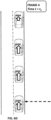
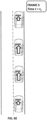
- Fig. 1 illustrates a convoy of motor-vehicles, where a vector of travel (i.e. direction, magnitude) is illustrated by arrows.
- a vector of travel i.e. direction, magnitude
- all vehicles are travelling at the same speed and in the same direction.
- vehicle 100B is behind and follows vehicle 100A
- vehicle 100C is behind and follows vehicle 100B
- vehicle 100D is behind and follows vehicle 100C.
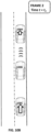
- Figs. 2A-2B illustrate one example of an accident between motor-vehicles 100A, 100B - Fig. 2A corresponds to an earlier moment in time before the accident occurs and Fig. 2B illustrate the moment immediately after the collision between motor-vehicles 100A, 100B.
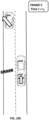
- Figs. 3A-3D illustrate a very specific type of accident - a chain accident.
- first 100A and second 100B vehicles are stopped and waiting at a stop sign as a third vehicle 100C approaches from behind.
- the third vehicle 100C hits the second vehicle 100B from behind, imparting to the second vehicle 100B forward momentum (Illustrated in Fig. 3C ).
- second vehicle 100B hits first vehicle 100A from behind.
- United States Patent Number 8,520,695 to Kim T Rubin and Jonathan Betts-LaCroix disclose the following: Device, system and method, in a vehicle communication system, to transmit wirelessly a message comprising the position, heading and speed of a vehicle or other moving object, wherein the transmission is repeated at regular intervals in a temporarily fixed time slot within a predetermined basic time interval.
- the message duration is equal to or less than a predetermined time slot duration.
- Embodiments use generally the same time slot in a contiguous sequence of basic time intervals. Algorithms are described to resolve wireless interference within a time slot.
- Embodiments divide the basic time interval in multiple durations, "class regions," for different message classes.
- Embodiments use different wireless bandwidth allocation algorithms for the class regions.
- Independent claims 1, 14 and 15 define the matter for which protection is sought, whereby claim 1 defines a method for attempting at least one of avoiding a potential motor-vehicle accident and minimizing damage caused by the potential motor-vehicle accident; claim 14 defines an anti-accident device; and claim 15 defines an anti-accident system.
- Dependent claims 2-13 concern particular embodiments of the invention as claimed in claim 1.
- An onboard device of a host motor-vehicle necessarily travels with the motor-vehicle as it moves - e.g. at the same velocity or substantially the same velocity.
- An onboard device is not required to be permanently associated with a motor-vehicle - in some embodiments, an onboard device may be temporarily associated with a motor-vehicle (e.g. a passenger manually brings a smartphone into the cabin of the car - for example, in his/her pocket). In other embodiments, an onboard device may be permanently associated with a motor-vehicle - i.e. a passenger cannot simply remove the device from the motor-vehicle without using a special tool.
- an onboard device may be disposed within the cabin, the engine compartment (e.g. attached to the engine or to a component thereof), under the chassis, on the roof, or in the baggage compartment of the motor-vehicle.
- Onboard devices may be mechanical, electronic or combinations thereof.
- Examples of an onboard device of a motor-vehicle include (i) onboard electronic circuitry (e.g. any combination of hardware and/or software - e.g. digital computer or code/software executing on a digital computer) , (ii) an onboard vehicle control (defined below), (iii) an onboard sensor (e.g. radar device, camera, etc.), (iv) an onboard transmitter or receiver of EM radiation (e.g. transmitter or receiver of non-visible EM radiation); and (v) an onboard passenger-safety device such as a seatbelt or an airbag.
- onboard electronic circuitry e.g. any combination of hardware and/or software - e.g. digital computer or code/software executing on a digital computer
- an onboard vehicle control defined below
- an onboard sensor e.g. radar device, camera, etc.
- an onboard transmitter or receiver of EM radiation e.g. transmitter or receiver of non-visible EM radiation
- an onboard device is said to reside (i.e. temporally or permanently) on (or to reside in) a host motor-vehicle.
- all motor-vehicles other than the host motor-vehicle are referred to as 'external' motor-vehicles.
- An onboard vehicle control may be situated in the cabin such as an accelerator pedal ('gas'), a decelerator pedal ('brake'), and a steering device (e.g. steering wheel).
- an onboard vehicle control may be outside of the cabin - for example, within the engine (e.g. a valve within the engine which regulates a flow of fuel), mounted to and under the vehicle, or in any other location.
- a device that is outside of the vehicle and not onboard, but which nevertheless sends signals that control the vehicle e.g. a wireless transmitter which wirelessly sends signals to onboard vehicle control(s) is not considered an onboard vehicle control, even if the wireless signals (i.e. once received at the vehicle and processed by onboard vehicle control(s)) affect the motion of the vehicle.
- the onboard vehicle control is mechanically coupled to an element of the engine or of the transmission system or of the braking system or of the steering system, and/or an electrical component of the onboard vehicle control is in wired or wireless communication with an element mechanically coupled to an element of the engine or of the transmission system or of the braking system or of the steering system.
- At least some factual input data can also be classified based upon the instrument (i.e. type of instrument or location of instrument) which acquires the factual input data.
- instrument-related categories of factual input data are:
- One example of updating an outcome prediction is as follows: Car B follows Car A and Car A suddenly starts braking . At time t1 , it is predicted in PREDICTION_A that the likelihood of an accident (car B hitting a rear of car A) occurring during the time interval [ t4 , t5 ] between Car 'A' and Car 'B' is 80%. At time t2, Car A reduces its braking force and Car B starts braking. At time t3, based upon the updated data and PREDICTION A, it is predicted in PREDICTION_B that the likelihood of an accident occurring during the time interval [ t4,t5 ] between Car 'A' and Car 'B' is now 40%.
- PREDICTION_B is based upon additional factual input data not available to PREDICTION_A.
- computationally predicting an accident scenario -- - a special case of computationally predicting an outcome where information about a ⁇ hypothetical accident' (i.e. an accident which did not occur yet at the time of the predicting and which may or may not occur) is predicted.
- Predicting an accident scenario may refer to at least one of: (i) predicting a likelihood of an hypothetical accident (including as special cases predicting that the accident is highly likely to occur and predicting that the accident is highly unlikely to occur); (ii) predicting one or more parameters of the hypothetical accident, which may be for example (A) which motor-vehicles will collide in the accident; (B) a ⁇ collision location' (e.g. front left fender, rear bumper, right door) of one or more motor-vehicles involved in the accident; (C) a severity of the accident.
- the result of predicting an accident scenario is the 'accident prediction data.'
- ⁇ computationally predicting an accident scenario' includes predicting one or more future vehicle control actions and the ⁇ accident prediction data' is generated in accordance with the predicting of the one or more future vehicle control actions.
- the predicting of an accident scenario may predict that the present factual input data (for example the cars' speed) will remain unchanged or that one or more vehicle control actions will soon take place and affect the accident prediction data.
- the given motor-vehicle performs a vehicle-control action that attempts to (i) prevent the potential motor-vehicle accident from occurring altogether (or at least, to reduce the probability that the potential motor-vehicle accident will occur); or (ii) without necessarily reducing the probability that the potential motor-vehicle accident will occur, reduce the likelihood that the given motor-vehicle will be involved in the potential motor-vehicle accident (if it occurs).
- Examples of attempts to avoid being involved in a potential motor-vehicle accidents may include employing the steering system to change a direction of travel in order to attempt to avoid hitting an object in front of the motor-vehicle, employing the braking system to slow the motor-vehicle in order to attempt to avoid hitting another motor-vehicle, increasing the power-output of the engine to increase the speed of a motor-vehicle in order to attempt to avoid being hit by another motor-vehicle(e.g. by engaging a throttle).
- Non-visible EM radiation is any EM radiation other than visible light.
- a wavelength of the EM radiation is greater than wavelengths of radiation in the visible spectrum - e.g. a wavelength of the EM radiation exceeds 800 nm or exceeds 900 nm or exceeds 1000 nm.
- EM radiation is infrared (IR) radiation.
- RF radiofrequency
- Another example is microwave radiation. It is noted that methods of transferring messages between motor-vehicles using non-visible EM radiation are well known in the art.
- Embodiments of the invention relate to computer-controlled driverless motor-vehicles that respond to computed predictions of potential accidents involving motor-vehicles that at least one of them is not directly adjacent to the computer-controlled motor-vehicle.
- accident alerts comprising accident prediction data are transmitted between motor-vehicles.
- vehicle 100D is also important for vehicle 100B- if vehicle 100D accelerates and strongly hits vehicle 100C from behind, then vehicle 100C will "jump forward" because of the hit and might itself hit vehicle 100B.
- vehicle 100C When vehicle 100C is hit from behind from vehicle 100D, this may cause vehicle 100C to travel forward at a speed faster than predicted by an onboard computer of vehicle 100B.
- vehicle 100B might not have enough time to react before vehicle 100C (i.e. which is travelling forward at speed that is faster than expected) hits vehicle 100B from behind.
- Second Example - the problem -- In the second example, it is desired to minimize a likelihood that vehicle 100C will be involved in an accident.
- Vehicle 100C monitors its distance from vehicle 100B and vehicle 100D, as these are the two vehicles that are adjacent to vehicle 100C and there is a risk of collision between either of these vehicles and vehicle 100C.
- vehicle 100A is also important for vehicle 100C - if vehicle 100A suddenly brakes and is hit by vehicle 100B, then vehicle 100B might encounter an immediate stop because of the hit and might itself be hit by vehicle 100C. Because of hitting vehicle 100A, vehicle 100B's stopping might be much faster than what vehicle 100C is expecting from a normally braking vehicle and vehicle 100C might not have enough time to react before hitting vehicle 100B.
- one vehicle alerts another vehicle about a potential accident, even though that potential accident involves a clash between the alerting car and a third vehicle.
- First example - solution In the case of the first example above (when vehicle 100D is about to hit vehicle 100C ) , at some point in time vehicle 100C will detect it is about to be hit by vehicle 100D or that there is a high probability (e.g. higher than some threshold probability) that it will be hit by vehicle 100D . Vehicle 100C will immediately transmit out that prediction as part of an accident alert, and this accident alert will be received by vehicle 100B. Note that at the time of receiving this accident alert at vehicle 100B, there might not yet be any indication from vehicle 100B's own sensors that anything unusual is about to happen. Thus, the proposed solution increases the time available to vehicle 100B to respond.
- a high probability e.g. higher than some threshold probability
- Vehicle 100B may respond to the accident alert by whatever response found to be optimal under the circumstances. For example, vehicle 100B may immediately accelerate forward in order to minimize the danger of being hit by vehicle 100C either as part of a chain accident or because vehicle 100C is accelerating to avoid being hit by vehicle 100D. Additionally, vehicle 100B may also pass an alert to vehicle 100A causing it to also accelerate so that vehicle 100B will not hit it from behind while trying to avoid being hit by vehicle 100C. Alternatively, vehicle 100B may reach a conclusion (i.e. an onboard computer of vehicle 100B may conclude) that the accident is unavoidable and then activate and hold its brakes as firmly as possible, so that when being hit it will not move too much, thus lowering the risk to its passengers.
- a conclusion i.e. an onboard computer of vehicle 100B may conclude
- alert messages may include not only an accident alert but also information about speed of cars adjacent to the message sender and distances between the message sender and the cars adjacent to it. Such information may be copied into secondary alerts triggered by an initial accident alert, thus spreading speed and distance information along the convoy to distant cars.
- Second example - solution In the case of the second example above (when vehicle 100B is about to hit vehicle 100A ), at some point in time vehicle 100B will detect it is about to hit vehicle 100A or that there is a high probability (e.g. higher than some threshold probability) that it will hit vehicle 100A . In this example, vehicle 100B will immediately transmit out that prediction, which will be received by vehicle 100C . Note that at the time of receiving this accident alert at vehicle 100C there might not yet be any indication from vehicle 100C' s own sensors that anything unusual is about to happen. Thus, the proposed solution increases the time available to vehicle 100C to respond.
- a high probability e.g. higher than some threshold probability
- Vehicle 100C may respond to the accident alert by whatever response found to be optimal under the circumstances. For example, vehicle 100C may immediately brake in order to minimize the danger of hitting vehicle 100B . Additionally, vehicle 100C may also pass an alert to vehicle 100D causing it to immediately brake so that vehicle 100D will not hit vehicle 100C from behind while vehicle 100C is trying to avoid hitting vehicle 100B . Alternatively, vehicle 100C may reach a conclusion (i.e. an onboard computer of vehicle 100C may conclude) that the accident is unavoidable and then adjust its speed to some optimal value that is considered to be optimal in the sense that it minimizes the overall damage to vehicle 100C passengers when vehicle 100C is being caught in the middle between vehicle 100B and vehicle 100D in a chain accident.
- a conclusion i.e. an onboard computer of vehicle 100C may conclude
- the decision rule may depend on the current speed of vehicle 100C, on the current speed of vehicle 100B , on the current speed of vehicle 100A, on the current speed of vehicle 100D , on the distance between vehicle 100B and vehicle 100C, on the distance between vehicle 100A and vehicle 100B , on the distance between vehicle 100C and vehicle 100D , or on any combination of such factors.
- vehicle 100C determines (i.e. an onboard computer of vehicle 100C determines) that it is about to hit vehicle 100B or that there is a high probability that it will hit vehicle 100B , then vehicle 100C will immediately transmit out that prediction (for the benefit of vehicle 100A and for the benefit of vehicle 100D and the car behind vehicle 100D ). But vehicle 100B can also receive that information and benefit from it.
- vehicle 100B is expected to learn about being hit from behind by vehicle 100C using its own sensors, it may be the case that its sensors are slow to respond by some reason or even that its sensors had failed and cannot detect the forthcoming accident.
- the accident alert by vehicle 100C acts as a backup for vehicle 100B 's sensors and may either increase vehicle 100B 's response time or may even be the only source for alerting vehicle 100B .
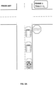
- Fig. 4 illustrates a method for attempting to avoid a potential motor-vehicle accident according to some embodiments.
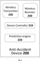
- Fig. 5 illustrates an exemplary anti-accident device 200 which may be disposed into any motor-vehicle that participates in the method of Fig. 4 .
- the anti-accident device 200 of Fig. 5 temporarily or permanently resides within a host motor-vehicle and thus is an onboard device of the motor-vehicle.
- Fig. 5 illustrates a method for attempting to avoid a potential motor-vehicle accident according to some embodiments.
- Fig. 5 illustrates an exemplary anti-accident device 200 which may be disposed into any motor-vehicle that participates in the method of Fig. 4 .
- the anti-accident device 200 of Fig. 5 temporarily or permanently resides within a host motor-vehicle and thus is an onboard device of the motor-vehicle.
- Fig. 5 illustrates a method for attempting to avoid
- the anti-accident device 200 includes (i) a prediction-engine 220 for processing factual input data about a plurality of motor-vehicles and computationally predicting an accident scenario, thereby generating output prediction data of a potential accident; (ii) a wireless transmitter 230 for wirelessly transmitting non-visual EM signals; (iii) a wireless receiver 240 for wirelessly receiving non-visual EM signals; and (iv) a device controller 210 for sending control signals to onboard vehicle controls of the host motor-vehicle where the anti-accident device resides.
- all components of the anti-accident device 200 are in wired communication with each other and/or in wired communication with at least one of the onboard vehicle controls of the host motor-vehicle.
- Anti-accident device 200 may include a digital computer (not illustrated in Fig. 5 ).
- a digital computer (not illustrated in Fig. 5 ).
- device controller 210 and prediction engine 220 may be implemented as a digital computer executing software.
- device controller 210 and prediction engine 220 may be implemented by separate digital computers.
- a common digital computer executes software to provide the functionality of both device controller 210 and prediction engine 220.
- any element illustrated in Fig. 5 may include and/or be implemented in "electronic circuitry," defined above.
- wireless transmitter 230 and receiver 240 are illustrated as separate units, they may be implemented as a single transceiver unit.
- the method of Fig. 4 requires three motor-vehicles,
- a respective anti-accident device 200 respectively resides in each of the three motor-vehicles and respectively controls its host vehicle.
- Figs. 6A-6E and 8A-8E respectively illustrate two non-limiting use cases of the method of Fig. 4 . Although these use cases are non-limiting, the method of Fig. 4 will first be explained with reference to Figs. 6A-6E .
- the use case of Figs. 6A-6E illustrates a convoy of motor-vehicles travelling in the same direction where initially ( Fig. 6A ) (i) motor-vehicles 600B and 600C are travelling at the same speed and (ii) front motor-vehicle 600A is travelling at a lower speed.
- a second motor-vehicle 600C follows a first motor-vehicle 600B, and a third motor-vehicle 600D follows the second motor-vehicle 600C.
- the first motor-vehicle 600B follows a fourth motor-vehicle 600A.
- a first accident alert is wirelessly transmitted by non-visual EM radiation from a first motor-vehicle (e.g. vehicle 600B of Fig. 6A ) - for example, by an onboard wireless transmitter 230 of an onboard anti-accident device 200 that resides in vehicle 600B.
- the first accident alert comprises accident prediction data about a potential motor-vehicle accident - for example, a potential accident where vehicle 600B hits vehicles 600A from behind.
- the accident prediction data is generated by an onboard computer (i.e. by an onboard prediction engine 220 implemented at least in part by a digital computer) of the first vehicle 600B according to factual input data - e.g. input data about the relative speeds of the first 600B vehicle and fourth vehicle 600A.
- the second motor-vehicle 600C may include front-looking sensors that monitor a speed of a vehicle 600B immediately in front of the second motor-vehicle 600C - these front-looking sensors may not be able to monitor a speed of the fourth vehicle 600A.
- a presence of first vehicle 600B may block an optical path between the second vehicle 600C and the fourth vehicle 600A.
- some or all of the accident prediction data of the first accident alert may be computed by an onboard computer and/or prediction engine of an anti-accident device residing in the first vehicle.
- step S121 the first accident alert is received at the second motor-vehicle (e.g. vehicle 600C )- for example, by an onboard wireless receiver 240 of an onboard anti-accident device 200 that resides in the second vehicle (e.g. vehicle 600C ).
- an onboard computer e.g. of a respective anti-accident device 200
- the second motor-vehicle e.g. vehicle 600C
- Step S141 is performed in response to the receiving of the first accident alert at the second motor-vehicle (e.g. vehicle 600C ).
- a second accident alert is wirelessly transmitted by non-visual EM radiation and from the second motor-vehicle - for the non-limiting use case of Figs. 6A-6E , step S141 is illustrated in Fig. 6C .
- the content of the first and second accident alerts may be the same, in which case the second vehicle 600C relays only the content received in the first accident alert.
- the content of the first and second accident alerts may be different - e.g. an onboard computer of the second vehicle may, for example, update an outcome prediction related to the first accident alert.
- onboard instruments of the second vehicle may acquire additional factual input data which is used to refine accident prediction data associated with the first accident alert, and this refined prediction data may be included in the second accident alert.
- step S161 the second accident alert is received at the third motor-vehicle (e.g. vehicle 600D )- for example, by an onboard wireless receiver 240 of an onboard anti-accident device 200 that resides in the third motor-vehicle (e.g. vehicle 600D ).
- Step S181 is performed in response to the receiving of the second accident alert at the third motor-vehicle (e.g. vehicle 600D ).
- an onboard computer e.g. prediction-engine 220 that is implemented by a digital computer executing software
- the third motor-vehicle e.g. vehicle 600D
- the vehicle control action(s) are performed so as to attempt (i) to avoid being involved in the potential motor-vehicle accident and/or (ii) to minimize damage inflicted upon the third motor-vehicle as a result of involvement in the potential motor-vehicle accident by performing at least one vehicle control action.
- FIG. 6E relates to one implementation of step S181 for the particular use-case of FIGS. 6A-6E .
- the third vehicle 600D may brake and/or decelerate - this is illustrated in FIG. 6E where the velocity arrow on vehicle 600D is of lesser magnitude than the velocity arrow on vehicle 600D in FIG. 6D .
- the trigger of the seconding of the first accident alert was the fourth vehicle 600A - i.e. the potential of an accident between the first 600B and fourth 600A vehicles.
- the second vehicle 600C may take advantage of the sensors of vehicle 600B which accesses input factual data that may not be available to the second vehicle 600C (e.g. due to a presence of the first 600B vehicle blocking a line-of-sight from the second vehicle 600C to the fourth vehicle 600A ).
- an action performed by the first 600B vehicle itself may trigger the sending of the first accident alert.
- the first vehicle 600B may drive over an unexpected patch of bad road which causes the first vehicle 600B to decelerate.
- First vehicle 600B then sends an accident alert warning second vehicle 600C of a potential accident that might occur if second vehicle 600C does not slow down.
- the deceleration of first vehicle 600B may eventually be detectable by sensors of the second vehicle 600C, but there is an advantage in alerting second vehicle 600C by first vehicle 600B because first vehicle 600B may be aware of the potential accident earlier than the sensors of second vehicle 600C.
- an elapsed time between commencement of step S101 and performance of step S181 is at most 500 milliseconds or at most 300 milliseconds or at most 100 milliseconds.
- a respective anti-accident device 200 resides (i.e. temporarily or permanently) on every motor vehicle of the three motor-vehicles referred to in the method of Fig. 4 .
- Each anti-accident device 200 is capable of providing all the functionality required from the first, second and third motor vehicles of the method of Fig. 4 - the particular functionality depends on the vehicle where the anti-accident device resides.
- the anti-accident device 200 when the anti-accident device 200 resides on the first vehicle, the anti-accident device provides the following functionality: in response to a predicting, by the prediction engine (i.e. of the anti-accident device 200 on the first vehicle) of an accident scenario about a first potential motor-vehicle accident (the ⁇ first potential motor-vehicle accident' corresponds to the ⁇ potential motor vehicle accident' of steps S101 and S181 ), the device controller (i.e. of the anti-accident device 200 on the first vehicle) transmits (see step S101 of Fig. 4 ), via the wireless transmitter (i.e. of the anti-accident device 200 on the first vehicle), a first outgoing accident alert comprising accident prediction data about the first potential motor-vehicle accident.
- the prediction engine i.e. of the anti-accident device 200 on the first vehicle
- the device controller i.e. of the anti-accident device 200 on the first vehicle
- transmits see step S101 of Fig. 4
- the anti-accident device 200 When the anti-accident device 200 resides on the second vehicle of Fig. 4 , the anti-accident device provides the following functionality: in response to a receiving (see step S121), via the wireless receiver (i.e. of the anti-accident device 200 on the second vehicle), of a first incoming accident alert (i.e. the 'first incoming accident alert' corresponds to the ⁇ first accident alert' of steps S121 and S141 of Fig. 4 ) comprising accident prediction data about a second potential motor-vehicle accident (the 'second potential motor-vehicle accident' corresponds to the ⁇ potential motor vehicle accident' of steps S101 and S181 ), the device controller (i.e.
- a second outgoing accident alert (i.e. the 'second outgoing accident alert' corresponds to the ⁇ second accident alert' of steps S141 and S161 of Fig. 4 ) comprising accident prediction data for the second potential motor-vehicle accident.
- the anti-accident device 200 When the anti-accident device 200 resides on the third vehicle of Fig. 4 , the anti-accident device provides the following functionality: in response to a receiving, via the wireless receiver (i.e. of the anti-accident device 200 on the third vehicle), of a second incoming accident alert (i.e. the 'second incoming accident alert' corresponds to the ⁇ second accident alert' of steps S141 and S161 of Fig. 4 ) comprising accident prediction data about a third potential motor-vehicle accident (the 'third potential motor-vehicle accident' corresponds to the ⁇ potential motor vehicle accident' of steps S101 and S181) between two or more external motor-vehicles (i.e.
- each of the external motor vehicles is a vehicle other than the 'third' motor vehicle of Fig. 4 - in Figs. 6A-6E vehicles 600A-600C are the external vehicles; in Figs. 8A-8E vehicles 120B-120D are the external vehicles), the device controller (i.e. of the anti-accident device 200 on the third vehicle) sends control signals to one or more onboard vehicle controls of the host motor-vehicle (i.e. the host motor vehicle corresponds to the third motor vehicle of Fig. 4 ) so as (A) to avoid involvement, of the host motor-vehicle (i.e. which corresponds to the third motor vehicle of Fig. 4 - e.g. vehicle 600D of Figs.
- the host motor-vehicle i.e. which corresponds to the third motor vehicle of Fig. 4 - e.g. vehicle 600D of Figs.
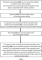
- Fig. 7A is similar to Fig. 4 but (i) includes an extra step S123 in which in response to the receiving of the first accident alert, computing an updated outcome prediction by an onboard computer of the second motor-vehicle , thereby generating updated accident prediction data and (ii) replaces step S141 of Fig. 4 with step S143 of Fig. 7A .
- one or more onboard computer(s) of the first motor-vehicle may compute accident prediction data of the first accident alert from a first set of factual input data; and (ii) one or more onboard computer(s) of the second motor-vehicle computes accident prediction data of the second accident alert from a second set of factual input data that includes factual input data not present within the first set of factual input data. For example, when the onboard computer(s) of the first motor-vehicle computes a probability of collision between the first (vehicle 600B of Figs. 6A-6E ) and second (vehicle 600C of Figs.
- the onboard computer(s) of the first motor-vehicle may not have available information (or may have inaccurate information) about the braking capability of the second vehicle 600C.
- the computed probability of collision might not necessarily be accurate.
- accurate information about the braking capability of the second vehicle 600C is available to the onboard computer of the second motor-vehicle (vehicle 600C of Figs. 6A-6E ) and this accurate information about braking capabilities of the second vehicle (vehicle 600C of Figs. 6A-6E ) may serve as factual input data in step S123.
- step S143 the second accident alert transmitted from the second motor-vehicle (vehicle 600C of Figs. 6A-6E ) comprises the updated accident prediction data based upon the accurate braking capability data of the second vehicle.
- Fig. 7B is similar to Fig. 4 but includes extra steps S125, S129 and S131.
- Fig. 7B relates to some examples where the accident prediction data of the received first accident alert is evaluated at the second motor-vehicle and the transmitting of the second accident alert from the second motor-vehicle is contingent upon the results of the evaluation.
- step S125 onboard computer of the second motor-vehicle evaluates S125 accident prediction data of the first accident alert - for example, to determine if a risk of an accident exceeds a risk-threshold or if a severity of an accident exceeds a severity-threshold. It may decide to refrain from performing step S141 for low-risk situations - for example, to avoid burdening the onboard computer of the third motor-vehicle or to avoid situations where the third motor-vehicle would needlessly change its velocity.
- step S129 it is determined (e.g. by onboard computer of the second motor-vehicle) if the results of the evaluating justify transmitting the second accident alert. If not (step S131 ) the second accident alert is not transmitted.
- Figs. 7A and 7B illustrate different potential modifications of the method of Fig. 4 - the skilled artisan will appreciate that these modifications may be combined in a single method.
- Fig. 4 was explained above for the particular example of Figs. 6A-6E where the second motor 600B vehicle follows the first motor-vehicle 600A and the third motor-vehicle 600C follows the second motor-vehicle. This is not a limitation.
- the second motor-vehicle 120B follows the third motor-vehicle 120A and the first motor-vehicle 120C follows the second motor-vehicle 120B .
- a fourth motor-vehicle 120D follows the first motor vehicle 120C.
- a first accident alert is wirelessly transmitted by non-visual EM radiation from a first motor-vehicle (e.g. vehicle 120C of Fig. 8A ) - for example, by an onboard wireless transmitter 230 of an onboard anti-accident device 200 that resides in vehicle 120C.
- the first accident alert comprises accident prediction data about a potential motor-vehicle accident - for example, a potential accident where vehicle 120D hits vehicle 120C from behind and thus vehicles in front of vehicle 120C are at risk of being involved in a chain accident.
- step S121 the first accident alert is received at the second motor-vehicle (e.g. vehicle 120B )- for example, by an onboard wireless receiver 240 of an onboard anti-accident device 200 that resides in the second vehicle (e.g. vehicle 120B ).
- Step S141 in performed in response to the receiving of the first accident alert at the second motor-vehicle (e.g. vehicle 120B ).
- a second accident alert is wirelessly transmitted by non-visual EM radiation and from the second motor-vehicle 120B - for the non-limiting use case of Figs. 8A-8E , step S141 is illustrated in Fig. 8C .
- this second accident alert may indicate that there is a non-zero probability that the second car 120B will be hit from behind.
- step S161 the second accident alert is received at the third motor-vehicle (e.g. vehicle 120A )- for example, by an onboard wireless receiver 240 of an onboard anti-accident device 200 that resides in third motor-vehicle (e.g. vehicle 120A ).
- Step S181 is performed in response to the receiving of the second accident alert at the third motor-vehicle (e.g. vehicle 120A ).
- an onboard computer e.g. prediction-engine 220 that is implemented by a digital computer executing software
- the third motor-vehicle e.g. vehicle 120A
- step S181 vehicle 120A according to step S181 is moving forward and to the right towards the shoulder of the road.
- Fig. 9 is a flow chart of a method for responding to a prediction of a potential car accident involving first, second and third motor-vehicles. Without limitation, the method of Fig. 9 will be explained with reference to the non-limiting example of Figs. 10A-10E - thus, in the non-limiting example, the first motor-vehicle is vehicle 100B, the second vehicle is vehicle 100C, and the third vehicle is vehicle 100A.
- the second motor 100C vehicle is behind the first 100B motor-vehicle and (ii) the first 100B motor-vehicle is behind the third 100A motor-vehicle.
- step S201 an onboard computer of a first motor-vehicle 100B computationally predicts an accident scenario indicating that the first 100B motor-vehicle might be hit from behind by a second motor-vehicle 100C.
- step S205 in response to the predicting, an accident alert is wirelessly transmitted, by non-visual EM radiation and from the first motor-vehicle 100B.
- step S209 the accident alert is received by a third motor-vehicle 100A that is in front of the first 100B motor-vehicle.
- step S213 in response to the receiving of the accident alert, an onboard computer of the third motor vehicle 100A attempts by performing at least one vehicle control action : (i) to avoid being hit from behind by the first motor-vehicle 100B and/or (ii) to reduce damage inflicted upon the third motor-vehicle 100A resulting from being hit from behind by the first motor-vehicle 100B.
- Fig. 10E The result is illustrated in Fig. 10E where the velocity of travel of vehicle 100A changes.
- vehicle 100A moves into the left lane to avoid being hit from behind by vehicle 100B.
- an elapsed time between commencement of step S201 and performance of step S213 is at most 500 milliseconds or at most 300 milliseconds or at most 100 milliseconds.
- a respective anti-accident device 200 resides (i.e. temporarily or permanently) on the first (e.g. 100B of Figs. 10A-10E ) and third (e.g. 100A of Figs. 10A-10E ) motor vehicles of the method of Fig. 9 .
- Each anti-accident device 200 is capable of providing all the functionality required from the first and third motor vehicles of the method of Fig. 9 - the particular functionality depends on the vehicle where the anti-accident device resides.
- the anti-accident device 200 when the anti-accident device 200 resides on the first vehicle (e.g. 100B of Figs. 10A-10E ) of the method of Fig. 9 , the anti-accident device provides the following functionality: in response to a predicting (e.g. performed in step S201 of Fig. 9 ) by the prediction-engine of the anti-accident device residing on the first vehicle (i.e. which is the host motor-vehicle device of the first anti-accident device - e.g. 100B of Figs. 10A-10E ) that the host motor-vehicle (i.e. first vehicle - e.g. 100B of Figs.
- the first external motor-vehicle i.e. the first external motor-vehicle is equivalent to the second motor vehicle of Fig. 9 - e.g. 100C of Figs. 10A-10E
- the first anti-accident device i.e. residing on the first vehicle - e.g. 100B of Figs. 10A-10E
- transmits e.g. see step S205 of Fig. 9
- an outgoing accident alert e.g. via the wireless transmitter of the anti-accident device residing on the first vehicle.
- the anti-accident device 200 When the anti-accident device 200 resides on the third vehicle (e.g. 100A of Figs. 10A-10E ) of the method of Fig. 9 , the anti-accident device provides the following functionality: in response to a receipt of an incoming accident alert (see step S209 of Fig. 9 ) that: (A) is received via a wireless receiver of the anti-accident device on the third vehicle (e.g. 100A of Figs. 10A-10E ); (B) is received from a second external motor-vehicle (i.e. the second external motor-vehicle is equivalent to the first motor vehicle of Fig. 9 -e.g. 100B of Figs.
- a second external motor-vehicle i.e. the second external motor-vehicle is equivalent to the first motor vehicle of Fig. 9 -e.g. 100B of Figs.
- the host motor-vehicle that is behind of the host motor-vehicle (i.e. when the anti-accident device resides on the third vehicle, the host motor-vehicle is the third vehicle - e.g. 100A of Figs. 10A-10E ); and (C). indicates that an accident might occur behind the host motor-vehicle (e.g. 100A of Figs. 10A-10E ) where the second external motor-vehicle (e.g. 100B of Figs. 10A-10E ) is hit from behind by a third external motor-vehicle (e.g. 100C of Figs. 10A-10E ), the device controller of the anti-accident device residing on the third vehicle of Fig.
- the host motor-vehicle i.e. when the anti-accident device resides on the third vehicle, the host motor-vehicle is the third vehicle - e.g. 100A of Figs. 10A-10E ); and (C).
- control signals sends control signals to one or more onboard vehicle controls of the host motor-vehicle (e.g. 100A of Figs. 10A-10E ).
- the control signals are sent so as to perform at least one vehicle control action in order to avoid the host motor-vehicle (i.e. this is the third vehicle of Fig. 9 - e.g. 100A of Figs. 10A-10E ) being hit from behind by the second external motor-vehicle (i.e. this is the first vehicle of Fig. 9 - e.g. 100B of Figs.
- Fig. 11 is a flow chart of a method for responding to a prediction of a potential accident involving first 100B, second 100A and third 100C motor-vehicles according to some embodiments of the invention. Without limitation, the method of Fig. 11 will be explained with reference to the non-limiting example of Figs. 12 - thus, in the non-limiting example, the first motor-vehicle is vehicle 100B, the second motor-vehicle is vehicle 100A, and the third motor-vehicle is vehicle 100C.
- an accident scenario is computationally predicted by an onboard computer of the first motor-vehicle 100B, the accident scenario indicating that a first motor-vehicle accident might occur between the first 100B and second 100A motor-vehicles - e.g. where the first 100B motor-vehicle hits the second 100A motor-vehicle from behind.
- first vehicle 100B is travelling faster than second vehicle 100A.
- an onboard computer of the first 100B motor-vehicle determines if changing a velocity of the first 100B motor-vehicle (e.g. by braking sharply) in order to (i) avoid the first motor-vehicle accident (i.e. where the first 100B motor-vehicle hits the second 100A motor-vehicle from behind) and/or (ii) reduce a likelihood thereof and/or (iii) reduce a severity thereof would (i) result in a second motor-vehicle accident between the first 100B and third 100C motor-vehicles (e.g.
- step S305 is performed in response to the predicting of step S301.
- the third motor-vehicle 100C is travelling faster than the first 100B motor-vehicle. In the event that the first 100B motor-vehicle brakes sharply, this could cause the third 100C motor-vehicle to hit the first 100B motor-vehicle from behind.
- step S309 in response to a positive determining (i.e. a determining that in fact the changing of the velocity of the first motor-vehicle 100B to avoid the first motor-vehicle accident would cause the second motor-vehicle accident to occur or could increase a likelihood thereof), an onboard computer of the first motor-vehicle 100B performs at least one vehicle control action by adjusting the velocity of the first motor-vehicle 100B according to respective velocities and/or accelerations of the second 100A and third motor 100C vehicles.
- a positive determining i.e. a determining that in fact the changing of the velocity of the first motor-vehicle 100B to avoid the first motor-vehicle accident would cause the second motor-vehicle accident to occur or could increase a likelihood thereof.
- an elapsed time between commencement of step S301 and performance of step S309 is at most 500 milliseconds or at most 300 milliseconds or at most 100 milliseconds.
- anti-accident device 200 resides (i.e. temporarily or permanently) on the first motor vehicle of the method of Fig. 11 (e.g. 100B of Fig. 12 ).
- This anti-accident device comprises a prediction-engine 220 for processing factual input data about a plurality of motor-vehicles and computationally predicting an accident scenario indicating that a first motor vehicle accident may occur between the host motor-vehicle (i.e. the first vehicle of Fig. 11 - e.g. 100B of Fig. 12 ) and a first external motor-vehicle (i.e. to the second motor-vehicle of Fig. 11 - e.g. 100C of Fig. 12 ).
- the host motor-vehicle i.e. the first vehicle of Fig. 11 - e.g. 100B of Fig. 12
- a first external motor-vehicle i.e. to the second motor-vehicle of Fig. 11 - e.g. 100C of Fig. 12 .
- the prediction-engine is further operative to determine if changing a velocity of the host motor-vehicle (i.e. the first vehicle of Fig. 11 - e.g. 100B of Fig. 12 ) in order (i) to avoid the first motor-vehicle accident and/or (ii) to reduce a likelihood thereof and/or (iii) to reduce a severity thereof, would result in one or more of: (A) a second motor-vehicle accident occurring between the host motor-vehicle (i.e. the first vehicle of Fig. 11 - e.g. 100B of Fig. 12 ) and a second external motor-vehicle (i.e. the third vehicle of Fig. 11 - e.g. 100A of Fig. 12 ) and (ii) an increase in a likelihood that the second motor-vehicle accident will occur.
- a second motor-vehicle accident occurring between the host motor-vehicle (i.e. the first vehicle of
- This anti-accident device further comprises a device controller 210 for responding to a positive determining by sending control signals (e.g. wired control signals) to one or more onboard vehicle controls of the host motor-vehicle (i.e. the first vehicle of Fig. 11 -e.g. 100B of Fig. 12 ) to adjust the velocity of the host motor-vehicle (i.e. the first vehicle of Fig. 11 - e.g. 100B of Fig. 12 ) according to respective velocities and/or accelerations of the first external motor-vehicle (i.e. the second vehicle of Fig. 11 - e.g. 100C of Fig. 12 ) and the second external motor-vehicle (i.e. the third vehicle of Fig. 11 - e.g. 100A of Fig. 12 ).
- control signals e.g. wired control signals
Claims (15)
- Procédé permettant de tenter au moins l'un d'un évitement d'un potentiel accident de véhicule à moteur et d'une minimisation de dommages causés par le potentiel accident de véhicule à moteur, le procédé comprenant :a. traitement par un moteur de prédiction (220), qui est au moins en partie mis en oeuvre par un calculateur numérique et qui est compris dans un dispositif anti-accident (200) résidant temporairement ou en permanence à l'intérieur d'un premier véhicule à moteur (600B), de données d'entrée factuelles concernant une pluralité de véhicules à moteur et prédiction par calcul d'un scénario d'accident, générant ainsi des données de prédiction d'accident du potentiel accident de véhicule à moteur, moyennant quoi la prédiction par calcul du scénario d'accident comprend la prédiction d'une ou plusieurs actions futures de commande de véhicule et les données de prédiction d'accident sont générées conformément à la prédiction de la ou des actions futures de commande de véhicule, moyennant quoi :i. les données d'entrée factuelles sont des faits qui sont entrés dans le moteur de prédiction (220) et qui sont utilisés par celui-ci pour faire ses prédictions,ii. les faits sont des faits actuels ou passés et n'impliquent aucune prédiction future ;iii. les données de prédiction d'accident sont définies en tant que cas particulier de données de prédiction de résultat qui sont générées par la prédiction par calcul du scénario d'accident ;b. l'émission sans fil (S101), par un rayonnement électromagnétique (EM) non visuel et à partir du premier véhicule à moteur (600B), d'une première alerte d'accident comprenant les données de prédiction d'accident concernant le potentiel accident de véhicule à moteur ;c. la réception (5121) de la première alerte d'accident au niveau d'un deuxième véhicule à moteur (600C) ;d. en réponse à la réception de la première alerte d'accident, l'émission sans fil (S141) d'une seconde alerte d'accident par rayonnement EM non visuel et à partir du deuxième véhicule à moteur (600C) ;e. la réception (S161) de la seconde alerte d'accident par un troisième véhicule à moteur (600D) ; etf. en réponse à la réception de la seconde alerte d'accident, la réalisation (S181) par un calculateur embarqué du troisième véhicule à moteur (600D) d'au moins une action de commande du véhicule de façon à tenter au moins un parmi les suivants :
(i) éviter d'être impliqué dans le potentiel accident de véhicule à moteur ; et (ii) minimiser des dommages infligés au troisième véhicule à moteur (600D) suite à une implication dans le potentiel accident de véhicule à moteur. - Procédé selon la revendication 1, (i) ladite seconde alerte d'accident comprenant des données de prédiction d'accident, et (ii) en plus des données de prédiction d'accident, ladite première alerte d'accident et/ou ladite seconde alerte d'accident comprenant des données d'entrée factuelles.
- Procédé selon la revendication 2, lesdites données d'entrée factuelles de la première et/ou de la seconde alerte d'accident comprenant une indication d'une action par un quatrième véhicule à moteur (600A).
- Procédé selon une quelconque revendication précédente, lesdites données de prédiction d'accident de la première alerte d'accident comprenant une indication qu'un accident pourrait se produire entre le premier véhicule à moteur et le deuxième véhicule à moteur.
- Procédé selon une quelconque revendication précédente, lesdites données de prédiction d'accident de la première alerte d'accident comprenant une indication qu'un accident pourrait se produire entre le premier véhicule à moteur et un quatrième véhicule à moteur.
- Procédé selon l'une quelconque des revendications 1-5, ledit deuxième véhicule à moteur suivant le premier véhicule à moteur et ledit troisième véhicule à moteur suivant le deuxième véhicule à moteur.
- Procédé selon l'une quelconque des revendications 1-5, ledit deuxième véhicule à moteur suivant le troisième véhicule à moteur et ledit premier véhicule à moteur suivant le deuxième véhicule à moteur.
- Procédé selon une quelconque revendication précédente, ladite au moins une action de commande de véhicule réalisée par le calculateur embarqué du troisième véhicule à moteur comprenant au moins l'une des actions suivantes : (i) accélération du troisième véhicule à moteur ; (ii) décélération du troisième véhicule à moteur ; (iii) utilisation d'un système de direction du troisième véhicule à moteur ; et (iv) utilisation d'un système de freinage du troisième véhicule à moteur.
- Procédé selon une quelconque revendication précédente, lesdites données de prédiction d'accident de la première alerte d'accident reçue étant évaluées au niveau du deuxième véhicule à moteur et ladite émission de la seconde alerte d'accident à partir du deuxième véhicule à moteur étant subordonnée aux résultats de l'évaluation.
- Procédé selon la revendication 1, (i) un ou plusieurs calculateur(s) embarqué(s) du premier véhicule à moteur calculant des données de prédiction d'accident de la première alerte d'accident à partir d'un premier ensemble de données d'entrée factuelles ; et (ii) un ou plusieurs calculateurs embarqués du deuxième véhicule à moteur calculant des données de prédiction d'accident qui sont comprises dans la seconde alerte d'accident, lesdites données de prédiction d'accident de la seconde alerte d'accident étant calculées à partir d'un second ensemble de données d'entrée factuelles qui comprend des données d'entrée factuelles non présentes dans le premier ensemble de données d'entrée factuelles.
- Procédé selon la revendication 1, (i) ladite seconde alerte d'accident comprenant des données de prédiction d'accident, et (ii) lesdites données de prédiction d'accident de la seconde alerte d'accident étant évaluées au niveau du deuxième véhicule à moteur et ladite émission de la seconde alerte d'accident à partir du deuxième véhicule à moteur étant subordonnées aux résultats de l'évaluation.
- Procédé selon la revendication 1, un ou plusieurs caculateur(s) embarqué(s) du deuxième véhicule à moteur dérivant des données de prédiction d'accident qui sont comprises dans la seconde alerte d'accident, lesdites données de prédiction d'accident de la seconde alerte d'accident étant dérivées uniquement des données de prédiction d'accident de la première alerte d'accident reçue.
- Procédé selon la revendication 2, lesdites données d'entrée factuelles de la première et/ou de la seconde alerte d'accident comprenant au moins une parmi : (i) une indication que le premier véhicule à moteur freine ; (ii) une indication que le premier véhicule à moteur décélère ; et (iii) une indication que le premier véhicule à moteur accélère.
- Dispositif anti-accident (200) destiné à fonctionner à bord d'un véhicule à moteur hôte (600), le dispositif anti-accident comprenant :a. un moteur de prédiction (220) qui est au moins en partie mise en oeuvre par calculateur numérique, ledit moteur de prédiction (220) étant destiné à traiter des données d'entrée factuelles concernant une pluralité de véhicules à moteur et prédire par calcul un scénario d'accident, générant ainsi des données de prédiction d'accident d'un potentiel accident, moyennant quoi la prédiction par calcul du scénario d'accident comprend la prédiction d'une ou de plusieurs actions futures de commande de véhicule et les données de prédiction d'accident sont générées conformément à la prédiction de la ou des actions futures de commande de véhicule, moyennant quoi les données d'entrée factuelles sont des faits qui sont entrés dans le moteur de prédiction (220) et sont utilisés par celui-ci pour faire ses prédictions, moyennant quoi les faits sont des faits actuels ou passés et n'impliquant aucune prédiction future, moyennant quoi les données de prédiction d'accident sont définies en tant que cas particulier de données de prédiction de résultat qui sont générées par la prédiction par calcul du scénario d'accident ;b. un émetteur sans fil (230) destiné à émettre sans fil des signaux électromagnétiques (EM) non visuels ;c. un récepteur sans fil (240) destiné à recevoir sans fil des signaux EM non visuels ; etd. un dispositif de commande de dispositif (210) destiné à envoyer des signaux de commande aux commandes de véhicule embarquées du véhicule à moteur hôte où réside le dispositif anti-accident, ledit dispositif embarqué anti-accident fournissant les caractéristiques suivantes :i. en réponse à une prédiction, par le moteur de prédiction, d'un scénario d'accident concernant un premier potentiel accident de véhicule à moteur, le dispositif de commande de dispositif émet, par l'intermédiaire de l'émetteur sans fil, une première alerte d'accident sortante comprenant des données de prédiction d'accident concernant le premier potentiel accident de véhicule à moteur ;ii. en réponse à une réception, par l'intermédiaire du récepteur sans fil, d'une première alerte d'accident entrante comprenant des données de prédiction d'accident concernant un deuxième potentiel accident de véhicule à moteur, le dispositif de commande de dispositif émet, par l'intermédiaire de l'émetteur sans fil, une seconde alerte d'accident sortante comprenant des données de prédiction d'accident pour le deuxième potentiel accident de véhicule à moteur ;iii. en réponse à la réception, par l'intermédiaire du récepteur sans fil, d'une seconde alerte d'accident entrante comprenant des données de prédiction d'accident concernant un troisième potentiel accident de véhicule à moteur entre deux, ou plus, véhicules à moteur externes, le dispositif de commande de dispositif envoie des signaux de commande à une ou plusieurs commandes de véhicules embarquées du véhicule à moteur hôte entraînant ainsi la réalisation d'au moins une action de commande du véhicule de façon à tenter au moins un parmi les suivants :(A) éviter toute implication du véhicule à moteur hôte dans le troisième potentiel accident de véhicule à moteur ; et(B) réduire les dommages infligés au véhicule à moteur hôte à la suite de son implication dans le troisième potentiel accident de véhicule à moteur.
- Système anti-accident comprenant :une pluralité de dispositifs anti-accident, chaque dispositif anti-accident donné de la pluralité comprenant respectivement :a. un moteur de prédiction respectif (220) qui est au moins en partie mis en oeuvre par calculateur numérique, ledit moteur de prédiction respectif (220)
étant destiné à traiter des données d'entrée factuelles concernant une pluralité de véhicules à moteur et prédire par calcul un scénario d'accident, générant ainsi des données de prédiction d'accident d'un potentiel accident, moyennant quoi des données d'entrée factuelles sont des faits qui sont entrés dans le moteur de prédiction (220) et sont utilisés par celui-ci pour faire ses prédictions, moyennant quoi les faits sont des faits actuels ou passés et n'impliquent aucune prédiction future, moyennant quoi les données de prédiction d'accident sont définies en tant que cas particulier de données de prédiction de résultat qui sont générées par la prédiction par calcul du scénario d'accident :i. ladite prédiction par calcul du scénario d'accident comprenant la prédiction d'une ou plusieurs actions futures de commande de véhicule ; etii. lesdites données de prédiction d'accident étant générées conformément à la prédiction de la ou des actions futures de commande de véhicule ;b. un émetteur sans fil respectif (230) destiné à émettre sans fil des signaux électromagnétiques (EM) non visuels ;c. un récepteur sans fil respectif (240) destiné à recevoir sans fil des signaux EM non visuels ; etd. un dispositif de commande de dispositif respectif (210) destiné à envoyer des signaux de commande aux commandes de véhicule embarquées d'un véhicule à moteur hôte respectif où le dispositif anti-accident donné réside temporairement ou en permanence,ladite pluralité de dispositifs anti-accident comprenant des premier, deuxième et troisième dispositifs anti-accident de sorte que, lorsque les premier, deuxième et troisième dispositifs anti-accident résident respectivement dans des premier (600B), deuxième (600C) et troisième (600D) véhicules à moteur, lesdits dispositifs anti-accident réalisant les opérations suivantes :i. le premier dispositif anti-accident émet sans fil, par rayonnement électromagnétique (EM) non visuel et à partir du premier véhicule à moteur (600B), une première alerte d'accident comprenant des données de prédiction d'accident sur un potentiel accident de véhicule à moteur ;ii. le deuxième dispositif anti-accident reçoit sans fil la première alerte d'accident, et répond en émettant sans fil une seconde alerte d'accident par un rayonnement EM non visuel ;iii. le troisième dispositif anti-accident reçoit sans fil la seconde alerte d'accident et répond en réalisant au moins une action de commande de véhicule de façon à tenter au moins un parmi les suivants : (A) éviter que le troisième véhicule à moteur (600D) soit impliqué dans le potentiel accident de véhicule à moteur et (B) réduire les dommages infligés au troisième véhicule à moteur (600D) à la suite de l'implication dans le potentiel accident de véhicule à moteur.
Applications Claiming Priority (2)
| Application Number | Priority Date | Filing Date | Title |
|---|---|---|---|
| US201562166795P | 2015-05-27 | 2015-05-27 | |
| PCT/IB2016/053102 WO2016189495A1 (fr) | 2015-05-27 | 2016-05-26 | Alerte d'accidents prédits entre des véhicules sans conducteur |
Publications (4)
| Publication Number | Publication Date |
|---|---|
| EP3304520A1 EP3304520A1 (fr) | 2018-04-11 |
| EP3304520A4 EP3304520A4 (fr) | 2019-02-20 |
| EP3304520C0 EP3304520C0 (fr) | 2023-09-20 |
| EP3304520B1 true EP3304520B1 (fr) | 2023-09-20 |
Family
ID=57393827
Family Applications (1)
| Application Number | Title | Priority Date | Filing Date |
|---|---|---|---|
| EP16799462.3A Active EP3304520B1 (fr) | 2015-05-27 | 2016-05-26 | Alerte d'accidents prédits entre des véhicules sans conducteur |
Country Status (3)
| Country | Link |
|---|---|
| US (1) | US9598078B2 (fr) |
| EP (1) | EP3304520B1 (fr) |
| WO (1) | WO2016189495A1 (fr) |
Families Citing this family (47)
| Publication number | Priority date | Publication date | Assignee | Title |
|---|---|---|---|---|
| WO2018039114A1 (fr) * | 2016-08-22 | 2018-03-01 | Peloton Technology, Inc. | Systèmes de formation de peloton de véhicules et procédés associés |
| US11334092B2 (en) | 2011-07-06 | 2022-05-17 | Peloton Technology, Inc. | Devices, systems, and methods for transmitting vehicle data |
| US10474166B2 (en) | 2011-07-06 | 2019-11-12 | Peloton Technology, Inc. | System and method for implementing pre-cognition braking and/or avoiding or mitigation risks among platooning vehicles |
| US10520952B1 (en) | 2011-07-06 | 2019-12-31 | Peloton Technology, Inc. | Devices, systems, and methods for transmitting vehicle data |
| US20170242443A1 (en) | 2015-11-02 | 2017-08-24 | Peloton Technology, Inc. | Gap measurement for vehicle convoying |
| US10520581B2 (en) | 2011-07-06 | 2019-12-31 | Peloton Technology, Inc. | Sensor fusion for autonomous or partially autonomous vehicle control |
| US8744666B2 (en) | 2011-07-06 | 2014-06-03 | Peloton Technology, Inc. | Systems and methods for semi-autonomous vehicular convoys |
| US11294396B2 (en) | 2013-03-15 | 2022-04-05 | Peloton Technology, Inc. | System and method for implementing pre-cognition braking and/or avoiding or mitigation risks among platooning vehicles |
| US8977376B1 (en) | 2014-01-06 | 2015-03-10 | Alpine Electronics of Silicon Valley, Inc. | Reproducing audio signals with a haptic apparatus on acoustic headphones and their calibration and measurement |
| DE102014214748A1 (de) * | 2014-07-28 | 2016-02-11 | Conti Temic Microelectronic Gmbh | Verfahren zum Durchführung eines Bremsvorgangs durch einen Bremsas-sistenten eines Kraftfahrzeugs |
| KR20170041162A (ko) * | 2014-09-05 | 2017-04-14 | 요코하마 고무 가부시키가이샤 | 충돌 회피 시스템 및 충돌 회피 방법 |
| KR101664582B1 (ko) * | 2014-11-12 | 2016-10-10 | 현대자동차주식회사 | 자율주행차량의 주행경로 생성장치 및 방법 |
| US10031522B2 (en) * | 2015-05-27 | 2018-07-24 | Dov Moran | Alerting predicted accidents between driverless cars |
| DE102015217275A1 (de) * | 2015-09-10 | 2017-03-16 | Robert Bosch Gmbh | Verfahren und Vorrichtung zum Bestimmen, ob ein Kraftfahrzeug momentan manuell oder automatisch geführt wird |
| KR102374735B1 (ko) * | 2015-09-14 | 2022-03-15 | 주식회사 만도모빌리티솔루션즈 | 운전지원장치 및 운전지원방법 |
| EP3465371A4 (fr) | 2016-05-31 | 2019-12-18 | Peloton Technology Inc. | Machine à états pour régulateur de peloton |
| US10839311B2 (en) * | 2016-07-19 | 2020-11-17 | International Business Machines Corporation | Cognitive computing for servers and mobile devices |
| US9760827B1 (en) * | 2016-07-22 | 2017-09-12 | Alpine Electronics of Silicon Valley, Inc. | Neural network applications in resource constrained environments |
| US10210451B2 (en) | 2016-07-22 | 2019-02-19 | Alpine Electronics of Silicon Valley, Inc. | Neural network applications in resource constrained environments |
| US10369998B2 (en) | 2016-08-22 | 2019-08-06 | Peloton Technology, Inc. | Dynamic gap control for automated driving |
| DE102016119502A1 (de) * | 2016-10-13 | 2018-04-19 | Valeo Schalter Und Sensoren Gmbh | Kategorisierung von Fahrzeugen in der Umgebung eines Kraftfahrzeugs |
| US10515390B2 (en) * | 2016-11-21 | 2019-12-24 | Nio Usa, Inc. | Method and system for data optimization |
| DE102017202415A1 (de) * | 2017-02-15 | 2018-08-16 | Bayerische Motoren Werke Aktiengesellschaft | Kollisionsvermeidung mit Querverkehr |
| US10495721B2 (en) * | 2017-02-24 | 2019-12-03 | Denso Corporation | Communication device, communication terminal device, communication method, and non-transitory tangible computer readable medium |
| CN110392907B (zh) * | 2017-03-07 | 2022-04-26 | 三菱电机株式会社 | 驾驶辅助装置、驾驶辅助方法及计算机可读取储存介质 |
| DE102017204416A1 (de) * | 2017-03-16 | 2018-09-20 | Robert Bosch Gmbh | Verfahren und Vorrichtung in einem Kraftfahrzeug zur Schadensminimierung bei Unfallsituationen |
| US10407014B2 (en) * | 2017-05-10 | 2019-09-10 | Ford Global Technologies, Llc | Vehicle underride impact detection systems and methods |
| US10948922B2 (en) | 2017-06-16 | 2021-03-16 | Sensors Unlimited, Inc. | Autonomous vehicle navigation |
| WO2018237018A1 (fr) | 2017-06-20 | 2018-12-27 | nuTonomy Inc. | Traitement de risque pour véhicules ayant des capacités de conduite autonome |
| EP3435355B1 (fr) * | 2017-07-28 | 2023-08-30 | Panasonic Intellectual Property Corporation of America | Appareil de traitement d'informations, procédé de traitement d'informations et support d'enregistrement |
| US10755115B2 (en) * | 2017-12-29 | 2020-08-25 | Here Global B.V. | Method, apparatus, and system for generating synthetic image data for machine learning |
| KR20190109850A (ko) * | 2018-03-19 | 2019-09-27 | 현대자동차주식회사 | 차량 및 그 제어 방법 |
| KR102479471B1 (ko) * | 2018-03-20 | 2022-12-22 | 모빌아이 비젼 테크놀로지스 엘티디. | 차량의 항법을 위한 시스템 및 방법 |
| EP3579443A1 (fr) * | 2018-06-07 | 2019-12-11 | Volkswagen Aktiengesellschaft | Véhicule, appareil, procédé et programme informatique permettant de communiquer dans de multiples systèmes de communication mobile |
| US10899323B2 (en) | 2018-07-08 | 2021-01-26 | Peloton Technology, Inc. | Devices, systems, and methods for vehicle braking |
| DE102018215509A1 (de) * | 2018-09-12 | 2020-03-12 | Robert Bosch Gmbh | Verfahren und Vorrichtung zum Betrieb eines zumindest teilweise automatisiert betriebenen ersten Fahrzeugs |
| US10762791B2 (en) | 2018-10-29 | 2020-09-01 | Peloton Technology, Inc. | Systems and methods for managing communications between vehicles |
| DE112018008144T5 (de) * | 2018-11-19 | 2021-08-12 | Mitsubishi Electric Corporation | Benachrichtigungssteuervorrichtung, Benachrichtigungsvorrichtung, Benachrichtigungssystem und Benachrichtigungssteuerverfahren |
| US10940870B1 (en) * | 2018-11-28 | 2021-03-09 | BlueOwl, LLC | Systems and methods for visualizing predicted driving risk |
| US11427196B2 (en) | 2019-04-15 | 2022-08-30 | Peloton Technology, Inc. | Systems and methods for managing tractor-trailers |
| US11267393B2 (en) * | 2019-05-16 | 2022-03-08 | Magna Electronics Inc. | Vehicular alert system for alerting drivers of other vehicles responsive to a change in driving conditions |
| KR20210019630A (ko) * | 2019-08-12 | 2021-02-23 | 현대자동차주식회사 | 대화형 자율 주행 시스템 |
| US10803334B1 (en) | 2019-10-18 | 2020-10-13 | Alpine Electronics of Silicon Valley, Inc. | Detection of unsafe cabin conditions in autonomous vehicles |
| FR3106433A1 (fr) * | 2020-01-20 | 2021-07-23 | Psa Automobiles Sa | Procédé et dispositif de communication pour véhicule |
| US11403948B2 (en) * | 2020-02-26 | 2022-08-02 | Compal Electronics, Inc. | Warning device of vehicle and warning method thereof |
| KR20220017562A (ko) * | 2020-08-04 | 2022-02-14 | 현대자동차주식회사 | 차량제어장치 및 방법 |
| CN112146673B (zh) * | 2020-09-27 | 2022-07-22 | 浙江综合交通大数据中心有限公司 | 基于改进蚁群算法的高速公路多点协同救援路径规划方法 |
Family Cites Families (118)
| Publication number | Priority date | Publication date | Assignee | Title |
|---|---|---|---|---|
| IT1248679B (it) | 1990-06-01 | 1995-01-26 | Enichem Anic Spa | Procedimento per la purificazione di fenolo |
| US7202776B2 (en) | 1997-10-22 | 2007-04-10 | Intelligent Technologies International, Inc. | Method and system for detecting objects external to a vehicle |
| US20060287783A1 (en) | 1998-01-15 | 2006-12-21 | Kline & Walker Llc | Automated accounting system that values, controls, records and bills the uses of equipment/vehicles for society |
| US6429016B1 (en) | 1999-10-01 | 2002-08-06 | Isis Pharmaceuticals, Inc. | System and method for sample positioning in a robotic system |
| US7143130B2 (en) | 1999-12-09 | 2006-11-28 | Ching-Fang Lin | Portable multi-tracking method and system |
| US7835864B1 (en) * | 2000-02-20 | 2010-11-16 | Dale F. Oexmann | Vehicle proximity detection and control systems |
| US6765495B1 (en) * | 2000-06-07 | 2004-07-20 | Hrl Laboratories, Llc | Inter vehicle communication system |
| US6571161B2 (en) | 2001-01-22 | 2003-05-27 | General Motors Corporation | Pre-crash assessment of crash severity for road vehicles |
| US20040254729A1 (en) | 2003-01-31 | 2004-12-16 | Browne Alan L. | Pre-collision assessment of potential collision severity for road vehicles |
| US6831572B2 (en) * | 2002-01-29 | 2004-12-14 | Ford Global Technologies, Llc | Rear collision warning system |
| US20130267194A1 (en) | 2002-06-11 | 2013-10-10 | American Vehicular Sciences Llc | Method and System for Notifying a Remote Facility of an Accident Involving a Vehicle |
| US7102496B1 (en) * | 2002-07-30 | 2006-09-05 | Yazaki North America, Inc. | Multi-sensor integration for a vehicle |
| US7098781B2 (en) | 2002-11-19 | 2006-08-29 | Ho Ling Wu | Vehicle braking alert system |
| US7797107B2 (en) | 2003-09-16 | 2010-09-14 | Zvi Shiller | Method and system for providing warnings concerning an imminent vehicular collision |
| JP2005301581A (ja) * | 2004-04-09 | 2005-10-27 | Denso Corp | 車車間通信システム、車車間通信装置及び制御装置 |
| US20080062011A1 (en) | 2004-09-07 | 2008-03-13 | Butler William M | Collision Avoidance Warning And Taxi Guidance Device |
| EP1717778B1 (fr) | 2005-04-29 | 2007-07-11 | Ford Global Technologies, LLC | Procédé et système pour l'empêchement de collision en avant pour un véhicule automobile |
| US7613569B2 (en) | 2005-07-19 | 2009-11-03 | Toyota Motor Engineering & Manufacturing North America, Inc. | Crash prediction network with visual input for vehicle |
| TWI287514B (en) * | 2005-11-03 | 2007-10-01 | Ind Tech Res Inst | Inter-vehicle communication and warning apparatus |
| US8050863B2 (en) | 2006-03-16 | 2011-11-01 | Gray & Company, Inc. | Navigation and control system for autonomous vehicles |
| US9373149B2 (en) | 2006-03-17 | 2016-06-21 | Fatdoor, Inc. | Autonomous neighborhood vehicle commerce network and community |
| US7425903B2 (en) * | 2006-04-28 | 2008-09-16 | International Business Machines Corporation | Dynamic vehicle grid infrastructure to allow vehicles to sense and respond to traffic conditions |
| US9635534B2 (en) | 2006-05-16 | 2017-04-25 | RedSky Technologies, Inc. | Method and system for an emergency location information service (E-LIS) from automated vehicles |
| US9067565B2 (en) | 2006-05-22 | 2015-06-30 | Inthinc Technology Solutions, Inc. | System and method for evaluating driver behavior |
| US8630768B2 (en) | 2006-05-22 | 2014-01-14 | Inthinc Technology Solutions, Inc. | System and method for monitoring vehicle parameters and driver behavior |
| US20080258890A1 (en) | 2006-05-22 | 2008-10-23 | Todd Follmer | System and Method for Remotely Deactivating a Vehicle |
| US20080294690A1 (en) | 2007-05-22 | 2008-11-27 | Mcclellan Scott | System and Method for Automatically Registering a Vehicle Monitoring Device |
| US8305936B2 (en) | 2006-07-27 | 2012-11-06 | Mobitrum Corporation | Method and system for dynamic information exchange on a mesh network in a vehicle |
| US20080212840A1 (en) | 2006-09-12 | 2008-09-04 | Tamir Shalom | Imaging system, method, and accessory therefor |
| GB2442776A (en) | 2006-10-11 | 2008-04-16 | Autoliv Dev | Object detection arrangement and positioning system for analysing the surroundings of a vehicle |
| US20080231835A1 (en) | 2007-03-23 | 2008-09-25 | Keigo Iizuka | Divergence ratio distance mapping camera |
| US8195343B2 (en) | 2007-05-19 | 2012-06-05 | Ching-Fang Lin | 4D GIS virtual reality for controlling, monitoring and prediction of manned/unmanned system |
| US20080291051A1 (en) | 2007-05-23 | 2008-11-27 | Hyslop William J | Relay warning system for a motor vehicle |
| US20090051510A1 (en) | 2007-08-21 | 2009-02-26 | Todd Follmer | System and Method for Detecting and Reporting Vehicle Damage |
| US8090489B2 (en) | 2007-11-09 | 2012-01-03 | Bruno Delean | Computerized driverless vehicles and traffic control system |
| US8031062B2 (en) | 2008-01-04 | 2011-10-04 | Smith Alexander E | Method and apparatus to improve vehicle situational awareness at intersections |
| US8212660B2 (en) | 2008-06-23 | 2012-07-03 | Frank Nugent | Overhead obstacle avoidance system |
| US20100019932A1 (en) * | 2008-07-24 | 2010-01-28 | Tele Atlas North America, Inc. | Driver Initiated Vehicle-to-Vehicle Anonymous Warning Device |
| US8126642B2 (en) | 2008-10-24 | 2012-02-28 | Gray & Company, Inc. | Control and systems for autonomously driven vehicles |
| US20100269920A1 (en) | 2009-01-22 | 2010-10-28 | Henning Albert K | Methods and apparatuses for complementary pneumatic devices and circuits |
| CA2692931A1 (fr) | 2009-02-16 | 2010-08-16 | Vehicules Nemo Inc. | Chassis monocoque pour vehicule |
| WO2010101749A1 (fr) | 2009-03-05 | 2010-09-10 | Massachusetts Institute Of Technology | Système de navigation de véhicule semi-autonome prédictif |
| US8629903B2 (en) | 2009-04-02 | 2014-01-14 | GM Global Technology Operations LLC | Enhanced vision system full-windshield HUD |
| US8352111B2 (en) * | 2009-04-06 | 2013-01-08 | GM Global Technology Operations LLC | Platoon vehicle management |
| US8882560B2 (en) | 2009-05-28 | 2014-11-11 | Anki, Inc. | Integration of a robotic system with one or more mobile computing devices |
| DE102009024083A1 (de) | 2009-06-05 | 2010-12-09 | Valeo Schalter Und Sensoren Gmbh | Verfahren zum Durchführen eines zumindest semi-autonomen Parkvorgangs eines Fahrzeugs und Parkassistenzsystem für ein Fahrzeug |
| US8207836B2 (en) | 2009-06-23 | 2012-06-26 | Frank Nugent | Overhead obstacle avoidance system |
| JP2011037308A (ja) * | 2009-08-06 | 2011-02-24 | Aisin Seiki Co Ltd | 車両用乗員保護システム |
| DE102009057836B4 (de) | 2009-12-10 | 2013-02-21 | Continental Teves Ag & Co. Ohg | Notbremsassistenzsystem zur Unterstützung eines Fahrers eines Fahrzeugs beim Anfahren |
| US8618922B2 (en) | 2010-03-30 | 2013-12-31 | GM Global Technology Operations LLC | Method and system for ensuring operation of limited-ability autonomous driving vehicles |
| US8855812B2 (en) | 2010-07-23 | 2014-10-07 | Chetan Kapoor | System and method for robot safety and collision avoidance |
| US8509982B2 (en) | 2010-10-05 | 2013-08-13 | Google Inc. | Zone driving |
| US8941510B2 (en) | 2010-11-24 | 2015-01-27 | Bcs Business Consulting Services Pte Ltd | Hazard warning system for vehicles |
| US8552886B2 (en) | 2010-11-24 | 2013-10-08 | Bcs Business Consulting Services Pte Ltd. | Crash warning system for motor vehicles |
| WO2012117057A1 (fr) | 2011-03-01 | 2012-09-07 | Continental Teves Ag & Co. Ohg | Dispositif de sécurité pour véhicule automobile et procédé permettant de faire fonctionner un véhicule automobile |
| US20120249341A1 (en) | 2011-03-30 | 2012-10-04 | Qualcomm Incorporated | Communication of emergency messages with road markers |
| DK2703925T3 (da) | 2011-04-28 | 2021-05-10 | Positec Power Tools Suzhou Co Ltd | Automatisk arbejdssystem, automatisk gangindretning og styrefremgangsmåde dertil |
| US9424606B2 (en) | 2011-04-28 | 2016-08-23 | Allstate Insurance Company | Enhanced claims settlement |
| DE102011104925A1 (de) | 2011-06-18 | 2012-12-20 | Daimler Ag | Kraftfahrzeug mit einer Fahrerassistenzeinheit |
| US8744666B2 (en) | 2011-07-06 | 2014-06-03 | Peloton Technology, Inc. | Systems and methods for semi-autonomous vehicular convoys |
| US20130018766A1 (en) | 2011-07-12 | 2013-01-17 | Edwin Roy Christman | Minimalist approach to roadway electrification |
| US8428863B2 (en) | 2011-07-13 | 2013-04-23 | Dynamic Research, Inc. | Devices, systems, and methods for testing crash avoidance technologies |
| US8447509B2 (en) | 2011-07-13 | 2013-05-21 | Dynamic Research, Inc. | System and method for testing crash avoidance technologies |
| US8589062B2 (en) | 2011-07-13 | 2013-11-19 | Dynamic Research, Inc. | Devices, systems, and methods for testing crash avoidance technologies |
| US8457877B2 (en) | 2011-07-13 | 2013-06-04 | Dynamic Research, Inc. | Devices, systems, and methods for testing crash avoidance technologies |
| US8583358B2 (en) | 2011-07-13 | 2013-11-12 | Dynamic Research, Inc. | Devices, systems, and methods for testing crash avoidance technologies |
| US9014915B2 (en) | 2011-07-25 | 2015-04-21 | GM Global Technology Operations LLC | Active safety control for vehicles |
| US9182761B2 (en) | 2011-08-25 | 2015-11-10 | Nissan Motor Co., Ltd. | Autonomous driving control system for vehicle |
| DE102011115223A1 (de) | 2011-09-24 | 2013-03-28 | Audi Ag | Verfahren zum Betrieb eines Sicherheitssystems eines Kraftfahrzeugs und Kraftfahrzeug |
| WO2013069195A1 (fr) | 2011-11-09 | 2013-05-16 | パナソニック株式会社 | Dispositif de locomotion autonome, procédé de locomotion autonome et programme pour dispositif de locomotion autonome |
| US9771070B2 (en) | 2011-12-09 | 2017-09-26 | GM Global Technology Operations LLC | Method and system for controlling a host vehicle |
| EP2615598B1 (fr) | 2012-01-11 | 2017-12-06 | Honda Research Institute Europe GmbH | Véhicule avec supports informatiques permettant de surveiller et de prévoir les réactions de participants au trafic |
| US9069075B2 (en) | 2012-02-10 | 2015-06-30 | GM Global Technology Operations LLC | Coupled range and intensity imaging for motion estimation |
| US8976040B2 (en) | 2012-02-16 | 2015-03-10 | Bianca RAY AVALANI | Intelligent driver assist system based on multimodal sensor fusion |
| US9429943B2 (en) | 2012-03-05 | 2016-08-30 | Florida A&M University | Artificial intelligence valet systems and methods |
| US20130238181A1 (en) | 2012-03-12 | 2013-09-12 | Toyota Motor Eng. & Man. North America (Tema) | On-board vehicle path prediction using processed sensor information |
| US8457827B1 (en) | 2012-03-15 | 2013-06-04 | Google Inc. | Modifying behavior of autonomous vehicle based on predicted behavior of other vehicles |
| US8700251B1 (en) | 2012-04-13 | 2014-04-15 | Google Inc. | System and method for automatically detecting key behaviors by vehicles |
| US20130278441A1 (en) | 2012-04-24 | 2013-10-24 | Zetta Research and Development, LLC - ForC Series | Vehicle proxying |
| US20130321627A1 (en) | 2012-05-31 | 2013-12-05 | John C. Turn, JR. | Road departure sensing and intelligent driving systems and methods |
| KR101393921B1 (ko) | 2012-05-31 | 2014-05-12 | 현대자동차주식회사 | 차량간 통신을 이용한 장애물 감지 장치 및 방법 |
| US20130325202A1 (en) | 2012-06-01 | 2013-12-05 | GM Global Technology Operations LLC | Neuro-cognitive driver state processing |
| US20130327244A1 (en) | 2012-06-11 | 2013-12-12 | Transit-21, Inc. (A Florida Corporation) | Autonomous moving highway |
| US9187091B2 (en) | 2012-07-30 | 2015-11-17 | Ford Global Technologies, Llc | Collision detection system with a plausibiity module |
| US20140129075A1 (en) | 2012-11-05 | 2014-05-08 | Dennis M. Carleton | Vehicle Control Using Modeled Swarming Behavior |
| US20140142868A1 (en) | 2012-11-18 | 2014-05-22 | Andian Technologies Ltd. | Apparatus and method for inspecting track in railroad |
| US9776587B2 (en) | 2012-11-29 | 2017-10-03 | Here Global B.V. | Method and apparatus for causing a change in an action of a vehicle for safety |
| US9227322B2 (en) | 2012-11-30 | 2016-01-05 | Fanuc Robotics America Corporation | Multi-arm robotic painting process synchronization |
| EP2746126B1 (fr) | 2012-12-18 | 2019-04-10 | Honda Research Institute Europe GmbH | Système d'assistance au conducteur |
| US9405296B2 (en) | 2012-12-19 | 2016-08-02 | Elwah LLC | Collision targeting for hazard handling |
| US8880273B1 (en) | 2013-01-16 | 2014-11-04 | Google Inc. | System and method for determining position and distance of objects using road fiducials |
| CA2897988C (fr) | 2013-01-17 | 2021-05-25 | Siemens Healthcare Diagnostics Inc. | Procede hybride de prevention des collisions et gestion du transport d'objets |
| US20140218482A1 (en) | 2013-02-05 | 2014-08-07 | John H. Prince | Positive Train Control Using Autonomous Systems |
| US9110169B2 (en) | 2013-03-08 | 2015-08-18 | Advanced Scientific Concepts, Inc. | LADAR enabled impact mitigation system |
| GB2511750B (en) * | 2013-03-11 | 2015-07-29 | Jaguar Land Rover Ltd | A driving assistance system, vehicle and method |
| US8954205B2 (en) | 2013-06-01 | 2015-02-10 | Savari, Inc. | System and method for road side equipment of interest selection for active safety applications |
| US9454150B2 (en) | 2013-07-17 | 2016-09-27 | Toyota Motor Engineering & Manufacturing North America, Inc. | Interactive automated driving system |
| DE102013214383A1 (de) | 2013-07-23 | 2015-01-29 | Robert Bosch Gmbh | Verfahren und Vorrichtung zum Bereitstellen eines Kollisionsignals hinsichtlich einer Fahrzeugkollision, Verfahren und Vorrichtung zum Verwalten von Kollisionsdaten hinsichtlich Fahrzeugkollisionen sowie Verfahren und Vorrichtung zum Steuern zumindest einer Kollisionsschutzeinrichtung eines Fahrzeugs |
| US9394059B2 (en) | 2013-08-15 | 2016-07-19 | Borealis Technical Limited | Method for monitoring autonomous accelerated aircraft pushback |
| US9346547B2 (en) | 2013-08-26 | 2016-05-24 | Google Inc. | Mechanisms for lowering a payload to the ground from a UAV |
| US9216745B2 (en) | 2013-09-16 | 2015-12-22 | Disney Enterprises, Inc. | Shared control of semi-autonomous vehicles including collision avoidance in multi-agent scenarios |
| DE102013218812A1 (de) | 2013-09-19 | 2015-03-19 | Robert Bosch Gmbh | Fahrerassistenzsystem für ein Kraftfahrzeug |
| EP2865576B1 (fr) | 2013-10-22 | 2018-07-04 | Honda Research Institute Europe GmbH | Estimation de confiance composite pour systèmes d'assistance de conducteur prédictifs |
| TWI525009B (zh) * | 2013-11-11 | 2016-03-11 | 緯創資通股份有限公司 | 車輛預警系統及車輛預警方法 |
| US9212926B2 (en) | 2013-11-22 | 2015-12-15 | Ford Global Technologies, Llc | In-vehicle path verification |
| US9834163B2 (en) | 2013-11-27 | 2017-12-05 | Bruce Kepley | Centripetal phase shift isolation control system, in an oscillation configuration of transposition, deflection, dampen, dissipation, and isolation of a stochastic vector |
| US20140327775A1 (en) | 2013-12-04 | 2014-11-06 | Kyu Hwang Cho | Mirrorless Driving of Automotive Vehicle Using Digital Image Sensors and Touchscreen |
| US20150161894A1 (en) * | 2013-12-05 | 2015-06-11 | Elwha Llc | Systems and methods for reporting characteristics of automatic-driving software |
| US9707942B2 (en) | 2013-12-06 | 2017-07-18 | Elwha Llc | Systems and methods for determining a robotic status of a driving vehicle |
| US9164507B2 (en) | 2013-12-06 | 2015-10-20 | Elwha Llc | Systems and methods for modeling driving behavior of vehicles |
| US9354623B2 (en) | 2014-02-20 | 2016-05-31 | Nabors Industries, Inc. | Methods and systems for pipe management on a drilling rig |
| US9233692B2 (en) | 2014-03-10 | 2016-01-12 | GM Global Technology Operations LLC | Method to control a vehicle path during autonomous braking |
| US20150261769A1 (en) | 2014-03-14 | 2015-09-17 | Joanne Uta Ono | Local Safety Network |
| US9266487B2 (en) | 2014-03-17 | 2016-02-23 | Ford Global Technologies, Llc | Adaptive suppression of vehicle restraint system |
| EP2923911B1 (fr) | 2014-03-24 | 2019-03-13 | Honda Research Institute Europe GmbH | Procédé et système de prédiction de comportement de mouvement d'un objet de trafic cible |
| US20150273697A1 (en) | 2014-03-27 | 2015-10-01 | Fatemah A.J.A. Abdullah | Robot for medical assistance |
| US9142127B1 (en) | 2014-04-29 | 2015-09-22 | Maxwell Consulting, LLC | Systems and methods for traffic guidance nodes and traffic navigating entities |
| BR112016029038B1 (pt) | 2014-06-11 | 2023-02-28 | Veridium Ip Limited | Sistema e método para facilitar acesso de usuário a veículos com base em informações biométricas |
-
2016
- 2016-05-26 US US15/165,668 patent/US9598078B2/en active Active
- 2016-05-26 EP EP16799462.3A patent/EP3304520B1/fr active Active
- 2016-05-26 WO PCT/IB2016/053102 patent/WO2016189495A1/fr active Application Filing
Also Published As
| Publication number | Publication date |
|---|---|
| EP3304520A1 (fr) | 2018-04-11 |
| WO2016189495A1 (fr) | 2016-12-01 |
| EP3304520C0 (fr) | 2023-09-20 |
| US9598078B2 (en) | 2017-03-21 |
| US20160347310A1 (en) | 2016-12-01 |
| EP3304520A4 (fr) | 2019-02-20 |
Similar Documents
| Publication | Publication Date | Title |
|---|---|---|
| EP3304520B1 (fr) | Alerte d'accidents prédits entre des véhicules sans conducteur | |
| US20220083056A1 (en) | Alerting predicted accidents between driverless cars | |
| US9841762B2 (en) | Alerting predicted accidents between driverless cars | |
| EP3208165B1 (fr) | Système d'assistance à la sécurité d'un véhicule | |
| EP2955077B1 (fr) | Système d'évaluation de dépassement et véhicule autonome avec un agencement d'évaluation de dépassement | |
| EP3018027B1 (fr) | Dispositif de commande conçu pour commander un véhicule autonome, agencement d'entraînement autonome, véhicule et procédé | |
| US11119492B2 (en) | Automatically responding to emergency service vehicles by an autonomous vehicle | |
| US11242040B2 (en) | Emergency braking for autonomous vehicles | |
| CN110406531A (zh) | 车辆防撞控制装置及其控制方法 | |
| CN108340866B (zh) | 防撞系统和方法 | |
| US10745004B2 (en) | Object recognizing device and collision avoidance system | |
| US11288964B2 (en) | Driving assistance device and driving assistance method | |
| CN109910880B (zh) | 车辆行为规划的方法、装置、存储介质和终端设备 | |
| US20210125431A1 (en) | Dynamic and variable learning by determining and using most-trustworthy inputs | |
| US20220126818A1 (en) | Systems and methods for identifying high-risk driving situations from driving data | |
| CN115440069B (zh) | 信息处理服务器、信息处理服务器的处理方法、非易失性存储介质 | |
| KR20200094629A (ko) | 운전자 보조 시스템 및 그 제어 방법 | |
| KR20200046611A (ko) | 운전자 보조 시스템 | |
| US11708075B2 (en) | Enhanced adaptive cruise control | |
| CN116494960A (zh) | 用于避免碰撞的方法、系统、车辆以及计算机程序产品 | |
| KR20230000655A (ko) | 차량 및 그 제어 방법 |
Legal Events
| Date | Code | Title | Description |
|---|---|---|---|
| STAA | Information on the status of an ep patent application or granted ep patent |
Free format text: STATUS: THE INTERNATIONAL PUBLICATION HAS BEEN MADE |
|
| PUAI | Public reference made under article 153(3) epc to a published international application that has entered the european phase |
Free format text: ORIGINAL CODE: 0009012 |
|
| STAA | Information on the status of an ep patent application or granted ep patent |
Free format text: STATUS: REQUEST FOR EXAMINATION WAS MADE |
|
| 17P | Request for examination filed |
Effective date: 20171219 |
|
| AK | Designated contracting states |
Kind code of ref document: A1 Designated state(s): AL AT BE BG CH CY CZ DE DK EE ES FI FR GB GR HR HU IE IS IT LI LT LU LV MC MK MT NL NO PL PT RO RS SE SI SK SM TR |
|
| AX | Request for extension of the european patent |
Extension state: BA ME |
|
| DAV | Request for validation of the european patent (deleted) | ||
| DAX | Request for extension of the european patent (deleted) | ||
| A4 | Supplementary search report drawn up and despatched |
Effective date: 20190123 |
|
| RIC1 | Information provided on ipc code assigned before grant |
Ipc: B60W 30/085 20120101ALI20190117BHEP Ipc: H04W 4/02 20180101ALI20190117BHEP Ipc: B60W 30/09 20120101ALI20190117BHEP Ipc: B60R 21/0134 20060101ALI20190117BHEP Ipc: G08G 1/16 20060101AFI20190117BHEP |
|
| STAA | Information on the status of an ep patent application or granted ep patent |
Free format text: STATUS: EXAMINATION IS IN PROGRESS |
|
| 17Q | First examination report despatched |
Effective date: 20220607 |
|
| GRAP | Despatch of communication of intention to grant a patent |
Free format text: ORIGINAL CODE: EPIDOSNIGR1 |
|
| STAA | Information on the status of an ep patent application or granted ep patent |
Free format text: STATUS: GRANT OF PATENT IS INTENDED |
|
| INTG | Intention to grant announced |
Effective date: 20230515 |
|
| GRAS | Grant fee paid |
Free format text: ORIGINAL CODE: EPIDOSNIGR3 |
|
| GRAA | (expected) grant |
Free format text: ORIGINAL CODE: 0009210 |
|
| STAA | Information on the status of an ep patent application or granted ep patent |
Free format text: STATUS: THE PATENT HAS BEEN GRANTED |
|
| AK | Designated contracting states |
Kind code of ref document: B1 Designated state(s): AL AT BE BG CH CY CZ DE DK EE ES FI FR GB GR HR HU IE IS IT LI LT LU LV MC MK MT NL NO PL PT RO RS SE SI SK SM TR |
|
| REG | Reference to a national code |
Ref country code: GB Ref legal event code: FG4D |
|
| REG | Reference to a national code |
Ref country code: CH Ref legal event code: EP |
|
| REG | Reference to a national code |
Ref country code: DE Ref legal event code: R096 Ref document number: 602016082904 Country of ref document: DE |
|
| REG | Reference to a national code |
Ref country code: IE Ref legal event code: FG4D |
|
| U01 | Request for unitary effect filed |
Effective date: 20230927 |
|
| U07 | Unitary effect registered |
Designated state(s): AT BE BG DE DK EE FI FR IT LT LU LV MT NL PT SE SI Effective date: 20231004 |
|
| PG25 | Lapsed in a contracting state [announced via postgrant information from national office to epo] |
Ref country code: GR Free format text: LAPSE BECAUSE OF FAILURE TO SUBMIT A TRANSLATION OF THE DESCRIPTION OR TO PAY THE FEE WITHIN THE PRESCRIBED TIME-LIMIT Effective date: 20231221 |
|
| PG25 | Lapsed in a contracting state [announced via postgrant information from national office to epo] |
Ref country code: RS Free format text: LAPSE BECAUSE OF FAILURE TO SUBMIT A TRANSLATION OF THE DESCRIPTION OR TO PAY THE FEE WITHIN THE PRESCRIBED TIME-LIMIT Effective date: 20230920 Ref country code: NO Free format text: LAPSE BECAUSE OF FAILURE TO SUBMIT A TRANSLATION OF THE DESCRIPTION OR TO PAY THE FEE WITHIN THE PRESCRIBED TIME-LIMIT Effective date: 20231220 Ref country code: HR Free format text: LAPSE BECAUSE OF FAILURE TO SUBMIT A TRANSLATION OF THE DESCRIPTION OR TO PAY THE FEE WITHIN THE PRESCRIBED TIME-LIMIT Effective date: 20230920 Ref country code: GR Free format text: LAPSE BECAUSE OF FAILURE TO SUBMIT A TRANSLATION OF THE DESCRIPTION OR TO PAY THE FEE WITHIN THE PRESCRIBED TIME-LIMIT Effective date: 20231221 |
|
| PG25 | Lapsed in a contracting state [announced via postgrant information from national office to epo] |
Ref country code: IS Free format text: LAPSE BECAUSE OF FAILURE TO SUBMIT A TRANSLATION OF THE DESCRIPTION OR TO PAY THE FEE WITHIN THE PRESCRIBED TIME-LIMIT Effective date: 20240120 |