EP3302912B1 - Verfahren und vorrichtung zum kontinuierlichen formen und aushärten von reifenlaufflächen - Google Patents
Verfahren und vorrichtung zum kontinuierlichen formen und aushärten von reifenlaufflächen Download PDFInfo
- Publication number
- EP3302912B1 EP3302912B1 EP16800452.1A EP16800452A EP3302912B1 EP 3302912 B1 EP3302912 B1 EP 3302912B1 EP 16800452 A EP16800452 A EP 16800452A EP 3302912 B1 EP3302912 B1 EP 3302912B1
- Authority
- EP
- European Patent Office
- Prior art keywords
- assembly
- mold
- upper platen
- platen assembly
- curing
- Prior art date
- Legal status (The legal status is an assumption and is not a legal conclusion. Google has not performed a legal analysis and makes no representation as to the accuracy of the status listed.)
- Active
Links
Images







Classifications
-
- B—PERFORMING OPERATIONS; TRANSPORTING
- B29—WORKING OF PLASTICS; WORKING OF SUBSTANCES IN A PLASTIC STATE IN GENERAL
- B29C—SHAPING OR JOINING OF PLASTICS; SHAPING OF MATERIAL IN A PLASTIC STATE, NOT OTHERWISE PROVIDED FOR; AFTER-TREATMENT OF THE SHAPED PRODUCTS, e.g. REPAIRING
- B29C43/00—Compression moulding, i.e. applying external pressure to flow the moulding material; Apparatus therefor
- B29C43/32—Component parts, details or accessories; Auxiliary operations
- B29C43/36—Moulds for making articles of definite length, i.e. discrete articles
- B29C43/3607—Moulds for making articles of definite length, i.e. discrete articles with sealing means or the like
-
- B—PERFORMING OPERATIONS; TRANSPORTING
- B29—WORKING OF PLASTICS; WORKING OF SUBSTANCES IN A PLASTIC STATE IN GENERAL
- B29C—SHAPING OR JOINING OF PLASTICS; SHAPING OF MATERIAL IN A PLASTIC STATE, NOT OTHERWISE PROVIDED FOR; AFTER-TREATMENT OF THE SHAPED PRODUCTS, e.g. REPAIRING
- B29C35/00—Heating, cooling or curing, e.g. crosslinking or vulcanising; Apparatus therefor
- B29C35/02—Heating or curing, e.g. crosslinking or vulcanizing during moulding, e.g. in a mould
- B29C35/0277—Apparatus with continuous transport of the material to be cured
-
- B—PERFORMING OPERATIONS; TRANSPORTING
- B29—WORKING OF PLASTICS; WORKING OF SUBSTANCES IN A PLASTIC STATE IN GENERAL
- B29C—SHAPING OR JOINING OF PLASTICS; SHAPING OF MATERIAL IN A PLASTIC STATE, NOT OTHERWISE PROVIDED FOR; AFTER-TREATMENT OF THE SHAPED PRODUCTS, e.g. REPAIRING
- B29C69/00—Combinations of shaping techniques not provided for in a single one of main groups B29C39/00 - B29C67/00, e.g. associations of moulding and joining techniques; Apparatus therefore
- B29C69/02—Combinations of shaping techniques not provided for in a single one of main groups B29C39/00 - B29C67/00, e.g. associations of moulding and joining techniques; Apparatus therefore of moulding techniques only
-
- B—PERFORMING OPERATIONS; TRANSPORTING
- B29—WORKING OF PLASTICS; WORKING OF SUBSTANCES IN A PLASTIC STATE IN GENERAL
- B29D—PRODUCING PARTICULAR ARTICLES FROM PLASTICS OR FROM SUBSTANCES IN A PLASTIC STATE
- B29D30/00—Producing pneumatic or solid tyres or parts thereof
- B29D30/06—Pneumatic tyres or parts thereof (e.g. produced by casting, moulding, compression moulding, injection moulding, centrifugal casting)
-
- B—PERFORMING OPERATIONS; TRANSPORTING
- B29—WORKING OF PLASTICS; WORKING OF SUBSTANCES IN A PLASTIC STATE IN GENERAL
- B29D—PRODUCING PARTICULAR ARTICLES FROM PLASTICS OR FROM SUBSTANCES IN A PLASTIC STATE
- B29D30/00—Producing pneumatic or solid tyres or parts thereof
- B29D30/06—Pneumatic tyres or parts thereof (e.g. produced by casting, moulding, compression moulding, injection moulding, centrifugal casting)
- B29D30/52—Unvulcanised treads, e.g. on used tyres; Retreading
-
- B—PERFORMING OPERATIONS; TRANSPORTING
- B29—WORKING OF PLASTICS; WORKING OF SUBSTANCES IN A PLASTIC STATE IN GENERAL
- B29C—SHAPING OR JOINING OF PLASTICS; SHAPING OF MATERIAL IN A PLASTIC STATE, NOT OTHERWISE PROVIDED FOR; AFTER-TREATMENT OF THE SHAPED PRODUCTS, e.g. REPAIRING
- B29C37/00—Component parts, details, accessories or auxiliary operations, not covered by group B29C33/00 or B29C35/00
- B29C37/006—Degassing moulding material or draining off gas during moulding
-
- B—PERFORMING OPERATIONS; TRANSPORTING
- B29—WORKING OF PLASTICS; WORKING OF SUBSTANCES IN A PLASTIC STATE IN GENERAL
- B29C—SHAPING OR JOINING OF PLASTICS; SHAPING OF MATERIAL IN A PLASTIC STATE, NOT OTHERWISE PROVIDED FOR; AFTER-TREATMENT OF THE SHAPED PRODUCTS, e.g. REPAIRING
- B29C43/00—Compression moulding, i.e. applying external pressure to flow the moulding material; Apparatus therefor
- B29C43/02—Compression moulding, i.e. applying external pressure to flow the moulding material; Apparatus therefor of articles of definite length, i.e. discrete articles
- B29C43/04—Compression moulding, i.e. applying external pressure to flow the moulding material; Apparatus therefor of articles of definite length, i.e. discrete articles using movable moulds
- B29C43/06—Compression moulding, i.e. applying external pressure to flow the moulding material; Apparatus therefor of articles of definite length, i.e. discrete articles using movable moulds continuously movable in one direction, e.g. mounted on chains, belts
-
- B—PERFORMING OPERATIONS; TRANSPORTING
- B29—WORKING OF PLASTICS; WORKING OF SUBSTANCES IN A PLASTIC STATE IN GENERAL
- B29C—SHAPING OR JOINING OF PLASTICS; SHAPING OF MATERIAL IN A PLASTIC STATE, NOT OTHERWISE PROVIDED FOR; AFTER-TREATMENT OF THE SHAPED PRODUCTS, e.g. REPAIRING
- B29C43/00—Compression moulding, i.e. applying external pressure to flow the moulding material; Apparatus therefor
- B29C43/02—Compression moulding, i.e. applying external pressure to flow the moulding material; Apparatus therefor of articles of definite length, i.e. discrete articles
- B29C43/04—Compression moulding, i.e. applying external pressure to flow the moulding material; Apparatus therefor of articles of definite length, i.e. discrete articles using movable moulds
- B29C43/06—Compression moulding, i.e. applying external pressure to flow the moulding material; Apparatus therefor of articles of definite length, i.e. discrete articles using movable moulds continuously movable in one direction, e.g. mounted on chains, belts
- B29C43/08—Compression moulding, i.e. applying external pressure to flow the moulding material; Apparatus therefor of articles of definite length, i.e. discrete articles using movable moulds continuously movable in one direction, e.g. mounted on chains, belts with circular movement, e.g. mounted on rolls, turntables
- B29C43/085—Compression moulding, i.e. applying external pressure to flow the moulding material; Apparatus therefor of articles of definite length, i.e. discrete articles using movable moulds continuously movable in one direction, e.g. mounted on chains, belts with circular movement, e.g. mounted on rolls, turntables and material fed in a continuous form, e.g. as a band
-
- B—PERFORMING OPERATIONS; TRANSPORTING
- B29—WORKING OF PLASTICS; WORKING OF SUBSTANCES IN A PLASTIC STATE IN GENERAL
- B29C—SHAPING OR JOINING OF PLASTICS; SHAPING OF MATERIAL IN A PLASTIC STATE, NOT OTHERWISE PROVIDED FOR; AFTER-TREATMENT OF THE SHAPED PRODUCTS, e.g. REPAIRING
- B29C43/00—Compression moulding, i.e. applying external pressure to flow the moulding material; Apparatus therefor
- B29C43/22—Compression moulding, i.e. applying external pressure to flow the moulding material; Apparatus therefor of articles of indefinite length
-
- B—PERFORMING OPERATIONS; TRANSPORTING
- B29—WORKING OF PLASTICS; WORKING OF SUBSTANCES IN A PLASTIC STATE IN GENERAL
- B29C—SHAPING OR JOINING OF PLASTICS; SHAPING OF MATERIAL IN A PLASTIC STATE, NOT OTHERWISE PROVIDED FOR; AFTER-TREATMENT OF THE SHAPED PRODUCTS, e.g. REPAIRING
- B29C43/00—Compression moulding, i.e. applying external pressure to flow the moulding material; Apparatus therefor
- B29C43/32—Component parts, details or accessories; Auxiliary operations
- B29C43/44—Compression means for making articles of indefinite length
-
- B—PERFORMING OPERATIONS; TRANSPORTING
- B29—WORKING OF PLASTICS; WORKING OF SUBSTANCES IN A PLASTIC STATE IN GENERAL
- B29C—SHAPING OR JOINING OF PLASTICS; SHAPING OF MATERIAL IN A PLASTIC STATE, NOT OTHERWISE PROVIDED FOR; AFTER-TREATMENT OF THE SHAPED PRODUCTS, e.g. REPAIRING
- B29C48/00—Extrusion moulding, i.e. expressing the moulding material through a die or nozzle which imparts the desired form; Apparatus therefor
- B29C48/03—Extrusion moulding, i.e. expressing the moulding material through a die or nozzle which imparts the desired form; Apparatus therefor characterised by the shape of the extruded material at extrusion
- B29C48/07—Flat, e.g. panels
- B29C48/08—Flat, e.g. panels flexible, e.g. films
-
- B—PERFORMING OPERATIONS; TRANSPORTING
- B29—WORKING OF PLASTICS; WORKING OF SUBSTANCES IN A PLASTIC STATE IN GENERAL
- B29K—INDEXING SCHEME ASSOCIATED WITH SUBCLASSES B29B, B29C OR B29D, RELATING TO MOULDING MATERIALS OR TO MATERIALS FOR MOULDS, REINFORCEMENTS, FILLERS OR PREFORMED PARTS, e.g. INSERTS
- B29K2021/00—Use of unspecified rubbers as moulding material
Definitions
- the subject matter of the present disclosure relates generally to a system for the continuous extrusion, molding, and curing of tread for tires.
- a rubber strip having a desired cross-sectional profile is extruded from a rubber-based formulation that is referred to herein as rubber or a rubber material.
- the rubber material typically includes a variety of components such as functional elastomers, resins, carbon black fillers, non-carbon black fillers, and/or other substances.
- the rubber is heated and fluidized. Pressure from the extruder screw forces the rubber through a die on the extruder outlet that imparts the desired profile to the rubber strip.
- the strip may be flat, have tapered sides, and include one or more ribs extending along its length.
- the extruded rubber strip is then wound and stored. Heat energy from extrusion process is usually lost as the rubber cools during the subsequent handling and storage.
- each rubber strip is unwound, cut to length, and positioned as separate pieces into a mold. Placement of each strip onto the mold requires carefully positioning each piece into the mold individually. Such placement may be performed in a manually intensive process that requires movement of the relatively heavy rubber strips. As part of the molding process, each rubber strip is reheated in the mold in order to cure the rubber and facilitate the molding of tread features into the rubber strip.
- tread rubber is then removed from the mold. Again, this may be performed manually. Each strip of tread rubber may then be stored again until it is applied to a tire carcass. Joining the tread strip with the tire carcass can require additional heating for completing the curing process and affixing the tire to the carcass.
- a system for the extrusion, molding, and curing of rubber to manufacture tread for tires would be useful.
- a system that can reduce or eliminate storage and reheating of the rubber between extrusion and molding would be beneficial.
- Such a system that can perform these operations continuously would be particularly useful.
- the present invention provides a system for the continuous extrusion, molding, and curing of tread for tires.
- An elongated strip of rubber material is molded and cured shortly after extrusion such that the material retains much of the heat energy of extrusion and does not have to be stored between extrusion and molding.
- the system uses a plurality of discrete mold assemblies that are conveyed adjacent to each other. As the mold assemblies are advanced sequentially, the uncured and unmolded strip of rubber material is extruded and positioned onto the mold assemblies. While the rubber strip advances, individual portions are sequentially molded and cured by passing through a mold press and then a curing press. A plug assembly is used to prevent the backflow of rubber material during the molding and curing. Additional objects and advantages of the invention will be set forth in part in the following description, or may be apparent from the description, or may be learned through practice of the invention.
- the present invention provides a method for continuous molding and curing of tire tread using a plurality of movable mold assemblies arranged adjacent to each other along a conveying direction.
- the method includes feeding an elongated strip of rubber material over a lower platen assembly; positioning the mold assemblies and a plug assembly over the lower platen assembly with the elongated strip of rubber material therebetween and the plug positioned upstream of, and adjacent to, the mold assemblies; pressing the mold assemblies and the plug assembly against the elongated strip of rubber material and the lower platen assembly; advancing the mold assemblies, the plug assembly, and the elongated strip of rubber material along the conveying direction; forcing the mold assemblies and the plug assembly against the elongated strip of rubber material and the lower platen assembly; heating at least portions of the elongated strip of rubber material during the forcing; and retracting the plug assembly away from the mold assemblies.
- the present invention provides an apparatus for the continuous molding and curing of tire tread.
- the apparatus defines a longitudinal axis parallel to an overall conveying direction of rubber material used to form the tire tread.
- the apparatus includes a plurality of movable mold assemblies.
- a mold assembly transport mechanism is arranged along the longitudinal axis and is configured for moving mold assemblies along the conveying direction.
- the mold assembly transport mechanism can also be used to constrain the mold assemblies as the rubber is molded and cured in the apparatus.
- the mold assembly transport mechanism has an in-feed end and an out-feed end.
- a lower platen assembly extends along the mold assembly transport mechanism.
- a first upper platen assembly is positioned near the in-feed end of the mold assembly transport mechanism and over the lower platen assembly.
- the first upper platen assembly is electively movable along a vertical direction relative to the lower platen assembly.
- a second upper platen assembly is positioned adjacent and downstream of the first upper platen assembly and over the lower platen assembly. The second upper platen assembly is selectively movable along the vertical direction relative to the lower platen assembly.
- a plug assembly is movable between i) a first position that is not under the first upper platen assembly or the second upper platen assembly and ii) a second position wherein the plug assembly is located between the first upper platen assembly and the lower platen assembly.
- the plug assembly is configured for selective placement against one of the movable mold assemblies so as to block a backflow of rubber material therefrom.
- FIGS. 1 , 2 , and 3 An exemplary apparatus 100 for the continuous extrusion, molding, and curing of tread rubber for tires is illustrated in perspective, side, and top views of FIGS. 1 , 2 , and 3 , respectively.
- Apparatus 100 includes several mechanisms, the features and operation of which will be further described herein with reference to exemplary embodiments and methods of operation.
- apparatus 100 defines a longitudinal axis L.
- Arrow F represents a conveying direction or the overall direction of flow of rubber material forming the tread.
- an elongated strip of rubber material 98 enters an infeed end 106 of apparatus 100 as uncured or green material that has not been molded with tread features.
- rubber strip 98 After passing through apparatus 100, rubber strip 98 exits outfeed end 118 in a cured state and with tread features molded therein. Portions of rubber strip 98 are molded and cured as it is moved along the conveying direction. Apparatus 100 can be operated without requiring strip 98 to be stored in e.g., rolls and/or experience the concomitant heat loss of such storage.
- apparatus 100 includes an extruder or extrusion machine 102 positioned near an in-feed end 106 of a mold assembly transport mechanism 104, which extends between ends 106 and 118.
- Extruder 102 receives rubber material and uses a rotating screw to mix and masticate the materials under elevated pressures and temperatures to create strip 98.
- One advantage of the present invention is that a variety of different rubber materials may be extruded and molded using the same apparatus 100 to provide a variety of treads requiring e.g., different processing conditions and/or dimensions.
- the processed rubber material exits extruder 102 as a continuous, elongated strip of rubber material 98 through extruder outlet 108.
- a die may be included with extruder outlet 108 to impart an overall shape or profile to the extruded rubber strip 98.
- Rollers 120 allow for compensation loops 96 in rubber strip 98, which can be used to ensure that a sufficient supply of rubber strip 98 is constantly available to apparatus 100 irrespective of the rate of output from extruder 102.
- rubber material (or rubber strip) 98 extends continuously along the longitudinal axis L of apparatus 100 through a molding press 110 and a curing press 112. Molding press 110 imparts tread features into portions of rubber strip 98 sequentially as it passes therethrough. Different molds may be used to create different tread features as needed for different tires sizes and types.
- the temperature of rubber strip 98 while in molding press 110 is within 5 degrees Celsius or less of the temperature of rubber strip 98 when it exits extruder 102.
- rubber strip 98 may be within a temperature range of 90 degrees Celsius to about 100 degrees Celsius as it exits extruder 102 and while in molding press 110. Other temperatures may be used as well.
- the present invention can advantageously avoid reheating rubber strip 98 after extrusion because strip 98 is molded shortly after its extrusion in order to minimize heat loss.
- Curing press 112 provides additional heat and pressure to partially or fully cure rubber strip 98 as it passes therethrough.
- the temperature of rubber strip 98 is heated to a temperature in the range of about 150 degrees Celsius to about 160 degrees Celsius to help cure rubber strip 98. Other temperatures may be used as well.
- Lower platen assembly 116 may include one or more platens extending through mold press 110 and curing press 112. Lower platen assembly 116 provides one or more surfaces against which elongated rubber strip 98 is pressed as part of molding and curing with apparatus 100.
- the vertical position (vertical direction V is denoted in FIGS. 1 and 2 ) of lower platen assembly 116 is fixed. Other configurations may be used as well. All or portions of lower platen assembly 116 can be equipped with features for heating rubber strip 98.
- lower platen assembly 116 may be provided with internal passages for the flow of a heat transfer fluid pumped therethrough.
- Rubber strip 98 may be tacky after it exits extruder 102.
- a roll 134 FIGS. 1 and 2
- anti-stick fabric 136 may be placed between rubber strip 98 and lower platen assembly 116 along apparatus 100.
- Fabric 136 moves with rubber strip 98 as it passed through apparatus 100 along conveying direction F and can facilitate such movement by reducing friction.
- lower platen assembly 116 may need to be cleaned even with use of the anti-stick fabric after a certain amount rubber material passes through. Other methods of preventing rubber strip 98 from sticking to lower platen assembly 116 may be used as well.
- a first upper platen assembly 122 in molding press 110 and a second upper platen assembly 124 in curing press 112 are each independently movable along vertical direction V relative to lower platen assembly 116.
- First upper platen assembly 122 can be lowered against mold assemblies 114 in molding press 110 to apply pressure and heat to mold tread features into rubber strip 98.
- second upper platen assembly 124 can be lowered against mold assemblies 114 in curing press 112 to apply pressure and heat to continue curing rubber strip 98.
- Both platen assemblies 122 and 124 can be raised to allow rubber strip 98 to be advanced along flow direction F and to allow for release of trapped gases in the rubber material.
- Each platen assembly 122 and 124 may be constructed from one or more individual platens.
- a plurality of motors 126 and 128 can be used to raise and lower platen assemblies 122 and 124, respectively.
- Motors 126 and 128 can be constructed as e.g., individually controlled hydraulic cylinders. As will be further described, the operation of motors 126 and 128 are synchronized with each other and the movement of rubber strip 98 through mold press 110 and curing press 112.
- each of the upper platen assemblies 122 and 124 can be equipped to apply heat to rubber strip 98 as it moves through apparatus 100.
- a frame 130 supports the platen assemblies and motors.
- the length along longitudinal direction L of curing press 112 is significantly longer than the length of molding press 110.
- curing press 112 could have a length along longitudinal direction L of about 5 meters while mold press 110 has a length along longitudinal direction L of about 1.5 meters. Other lengths and relative sizes may also be used.
- rubber strip 98 is translated along conveying direction F, which is parallel to longitudinal axis L. This is accomplished as mold assembly and transport mechanism 104 advances mold assemblies 114 along conveying direction F between infeed end 106 and outfeed end 118.
- Such movement of mold assembles 114 which are releasably connected with strip 98 as part of its molding and curing, causes rubber strip 98 to move simultaneously so as to translate rubber strip 98 through apparatus 100.
- rubber strip 98 passes from infeed end 106 to outfeed end 118 as a continuous strip of rubber material - advancing one mold assembly 114 at a time as such are added at infeed end 106 of mold assembly transport mechanism 104.
- transport mechanism 104 can include motorized rails, conveying chains, and/or other mechanisms to push, pull, or otherwise convey mold assemblies 114 along lower platen assembly 116.
- cured rubber strip 98 with now molded tread features must be demolded from mold assemblies 114 as such are advanced along conveying direction F.
- rubber strip 98 is pulled away from mold assembly 114z, passes around roller 132, and exits apparatus 100.
- Anti-stick fabric 136 may remain attached to rubber strip 98 or may be removed therefrom.
- rubber strip 98 can now be cut into tread sections of the desired size for storage and/or placement onto a tire carcass.
- Apparatus 100 includes a mold assembly return mechanism 200 for returning mold assemblies 114 from outfeed end 118 of apparatus 100 to infeed end 106 of apparatus 100.
- mold assemblies 114 After demolding from rubber strip 98, mold assemblies 114 are transferred laterally along transverse direction T from mold assembly transport mechanism 104 to mold assembly return mechanism 200.
- a pair of rails 202 can be used to support a mold assembly 114 during such lateral transfer.
- Mold assembly 114 is then moved, as indicated by arrow R, in a direction opposite to conveying direction F.
- Near infeed end 106 another pair of rails 204 allow mold assembly 114 to be transferred along transverse direction T from mold assembly return mechanism 200 back to mold assembly transport mechanism 104.
- mold assemblies 114 are circulated along a loop to provide a continuous supply for molding and translating rubber strip 98 along conveying direction F.
- rails 202, 204 and/or mold assembly return mechanism 200 may have a construction similar to mechanism 104 such as e.g., a motorized conveyor system, rails, and/or a plurality of rollers with one or more devices for transporting mold assemblies 114 along mechanism 200 in the direction of arrow R. Other constructions may be used as well.
- return mechanism 200 may include one or more heating devices for heating mold units 114 as such travel back to infeed end 106 on mechanism 200. Mold assembly return mechanism 200 could also be equipped with a mold cleaning device - removing rubber flashing and/or venting from the mold assemblies 114.
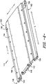
- FIGS. 4 , 5 , and 6 Top, bottom, and end views of an exemplary molding assembly 114 are set forth in FIGS. 4 , 5 , and 6 .
- a plurality of tread sectors 138, 140 and 142 are attached to a mold back 144. While three tread sectors are shown, one or more tread sectors may be attached to each molding assembly 114.
- Each tread sector 138, 140, and 142 contains mold features 146 for molding tread features into rubber strip 98 so as to create tire tread.
- One or more molding assemblies 114 may be required to create the entire length of tread needed for a single tire depending upon e.g., the relative lengths of the tire tread and molding assembly 114.
- each mold assembly 114 includes an upstream end 148 and a downstream end 150. Mold assemblies 114 are equipped with locking mechanisms at ends 148 and 150 for releasably interlocking or connecting with adjacent mold assemblies 114 while on transport mechanism 104.
- upstream end 148 has a locking mechanism that includes an opposing pair of upwardly directed hooks or latches 152 and 154.
- Downstream end 150 has a locking mechanism that includes an opposing pair of downwardly directed hooks or latches 156 and 158.
- hooks 156 and 158 maintain alignment between mold assemblies 114 in the transverse and longitudinal directions. Clamps 168, 170 press and maintain alignment along vertical direction V.
- latch 152 and 154 of one mold assembly 114 will engage or connect in a complementary manner with latches 156 and 158 of another, upstream mold assembly 114. Such connected will keep each mold assembly 114 in contact with one or two adjacent mold assemblies 114 as such translate through apparatus 100.
- the latches can be engaged and disengaged by displacing one mold assembly 114 relative to another along vertical direction V.
- Latches 152, 154, 156, and 158 are provided by way of example only. Other selectively releasable locking mechanisms may be used as well.
- FIG. 6 provides an exploded end view of mold assembly 114 positioned above lower platen assembly 116.
- Arrows P represents the downward force of pressure applied to mold assembly 114 by platen assemblies 122 or 124, which in turn causes mold features 146 to impart tread features into rubber strip 98 and cure the same.
- Mold assembly 114 includes a pair of opposing lateral edges 160 and 162 that are separated from each other along transverse direction T.
- lateral edge 160 is positioned in a slot 164 formed between guide rail 168 and lower platen assembly 116 while lateral edge 162 is placed in a slot 166 formed between guide rail 170 and lower platen assembly 116.
- Clamps 168 and 170 include rollers 176 and 178 that facilitate the centering of mold assemblies 114 as such are moved in conveying direction F along the longitudinal axis L or longitudinal direction L of apparatus 100 by transport mechanism 104.
- Roller 172 and 174 can be selectively extended and retracted along vertical direction V.
- mold assemblies 114 are advanced in step-like manner along conveying direction F as rubber strip 98 is continuously extruded, molded, and cured.
- rollers 172 and 174 are extended upwardly along vertical direction to lift the mold assemblies 114 away from lower platen assembly 116 and thereby facilitate movement along conveying direction F.
- rollers 172 and 174 retract, which lowers mold assemblies 114 back into contact with lower platen 116.
- a plug assembly 184 is used to prevent the backflow of rubber material from mold assemblies 114 when pressure is applied in the molding press or curing press.
- plug assembly 184 is blank - i.e. it does not include a tread sector and, instead, has a flat surface 186 so as not to impart tread features into rubber strip 98.
- plug assembly 184 includes a releasable locking mechanism for selective attachment with a mold assembly 114.
- downstream end 188 includes an opposing pair of downwardly facing latches 190 and 192 for complementary engagement with opposing latches 152 and 154 on the upstream end 148 of a mold assembly 114.
- plug assembly 184 By displacing plug assembly 184 relative to mold assembly 114 along vertical direction V, plug assembly 184 can be selectively engaged and disengaged from a mold assembly 114. Similar to mold assemblies 114, plug assembly 184 includes lateral edges 194 and 196 that can be extend into, and retracted out of, slots 164 and 166 during operation of apparatus 100.
- plug assembly 184 can be equipped with a spacer 198 for purposes of adjustment.
- Interchangeable spacer 198 can be positioned onto surface 186 of plug assembly 184 and used to selectively adjust the amount of space or height H along vertical direction V between rubber strip 98 and flat surface 210 of spacer 194. In turn, this allows the amount of resistance to the backflow of rubber from an adjacent mold assembly 114 to be adjusted (using spacers 194 of different thicknesses of heights) as part of the setup and operation of apparatus 100.
- the term “method” or “process” refers to one or more steps that may be performed in other ordering than shown without departing from the scope of the presently disclosed invention.
- the term “method” or “process” may include one or more steps performed at least by one electronic or computer-based apparatus. Any sequence of steps is exemplary and is not intended to limit methods described herein to any particular sequence, nor is it intended to preclude adding steps, omitting steps, repeating steps, or performing steps simultaneously.
- the term “method” or “process” may include one or more steps performed at least by one electronic or computer-based apparatus having a processor for executing instructions that carry out the steps.
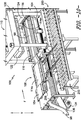
- apparatus 100 is shown with mold press 110 in an open position wherein first upper platen assembly 122 has been raised away from lower platen assembly 116.
- Curing press 112 is depicted in a closed position wherein second upper platen assembly 124 has been lowered onto several mold assemblies include mold assembly 114m and is pressing such mold assemblies against elongated rubber strip 98 and lower platen assembly 116.
- second upper platen assembly 124 is also heating rubber strip 98 to provide for curing.
- plug assembly 184 is depicted in a retracted or "first position" where it is not located between first upper platen assembly 122 and lower platen assembly 116.
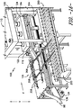
- Lift cylinders 206 have also raised plug assembly 184 in preparation for connecting a mold assembly 114 thereto. While plug assembly 184 is in this first position, a first mold assembly 114a is shifted transversely (arrow J) by way of rails 204 from mold assembly return mechanism 200 as shown in FIG. 9 to mold assembly transport mechanism 104 as shown in FIG. 10 .
- a plurality of lift cylinders 208 are used to raise (arrows U) mold assembly 114a along vertical direction V.
- This vertical motion engages latches 152 and 154 along upstream end 148 of mold assembly 114a with latches 190 and 192 on a downstream end 188 of plug 184 ( FIG. 7 ) - thereby releasably connecting or linking plug 184 and mold assembly 114a.
- mold assembly 114a is not yet located between first upper platen assembly 122 and lower platen assembly 116.
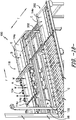
- mold assembly 114a is advanced (arrows A) along conveying direction F to a position between first upper platen assembly 122 and lower platen assembly 116.
- plug assembly 184 has also been advanced (arrows A) from the first position shown in FIGS. 9 , 10 and 11 , to a second position where plug assembly 184 is upstream of, and adjacent to, a plurality mold assemblies 114 (including mold assembly 114a). In this section position, plug assembly 184 is also between first upper platen assembly 122 and lower platen assembly 116 - but is not adjacent to second upper platen assembly 124.
- mold assembly 114a and plug assembly 184 are positioned over elongated rubber strip 98, which has been fed over lower platen assembly 116 from extruder 102.
- first upper platen assembly 122 is lowered (arrows N) to press plug assembly 184 and mold assembly 114a against lower platen assembly 116.
- Such pressing molds tread features into that portion of rubber strip 98 that is located between mold assembly 114a and lower platen assembly 116. Heat may also be transferred to rubber strip 98 from first upper platen assembly 122.
- the pressure applied to plug assembly 184 blocks or prevents the uncured rubber material of such portion of strip 98 from flowing away from mold assembly 114a and counter to flow direction F.
- second upper platen assembly 124 continues to press a plurality of downstream mold assemblies 114 against downstream portions of rubber strip 98 to continue the curing process.
- both molding press 110 and curing press 112 are in a closed position.
- first upper platen assembly 122 and second upper platen assembly 124 are each raised a short distance along vertical direction V so that mold press 110 and curing press 112 are both open.
- Rollers 172 and 174 are raised along vertical direction V (e.g., 1-2 mm) to thereby raise the plurality of mold assemblies 114 on transport mechanism 104 (including mold assembly 114a and mold assembly 114m) positioned below first and second upper platen assemblies 122 and 124.
- mold assembly transport mechanism 104 advances mold assemblies 114 (including mold assemblies 114a and 114m) along the conveying direction F.
- Plug assembly 184, rubber strip 98, and fabric 136 also advance simultaneously with the movement of mold assemblies 114.
- plug assembly 184 now occupies a third position along longitudinal direction L where it is below the first upper platen assembly 122 and will be adjacent to the second upper platen assembly 124 when press 112 is closed.
- the amount of movement along conveying direction F is equal to the length along longitudinal direction L of a mold assembly 114.
- first upper platen assembly 122 and second upper platen assembly 124 are again lowered (arrows Q) to force plug assembly 184 and molding assemblies 114 (including mold assembly 114a and 114m) against rubber strip 98 and lower platen assembly 116. Rollers 172 and 174 are simultaneously retracted during such lowering to help balance assembles 114. Heat can also be applied to second upper platen assembly 124 to help cure rubber strip 98.
- plug assembly 184 prevents the backflow of rubber material from beneath second upper platen assembly 124. As previously indicated, the thickness of spacer 194 ( FIG. 8 ) is selected so as to prevent such backflow.
- first upper platen assembly 122 is raised (arrows Z) along vertical direction V to release plug assembly 184.
- plug assembly 184 is retracted back (arrow K) back to its first position (depicted in FIG. 9 ).
- a second mold assembly 114z is now ready to be transferred along transverse direction T from mold assembly return mechanism 200 to repeat the process just described beginning with FIG. 9 .
- FIG. 19 illustrates tread 98 being demolded from mold assembly 114y.
- broken arrows G denote the movement of molding assembly 114z through positions A, B, and C.
- mold assembly 114z is lowered (arrows M) along vertical direction V so as to disconnect it from mold assembly 114y.
- Such lowering allows latches 152 and 154 on the upstream end 148 of mold assembly 114z to be released from latches 156 and 158 on the downstream end 150 of mold assembly 114y (see FIGS. 4 and 5 ).
- Mold assembly 114z is then advanced along flow direction F to position B. From position B on mold assembly transport mechanism 104, mold assembly 114z can be moved along transverse direction T over rails 202 to mold assembly return mechanism 200 at position C. As previously described, mold assembly return mechanism moves mold assembly 114z from outfeed end 118 to infeed end 106 at the position shown in FIG. 17 . From this location, mold assembly 114z can be transferred onto mold assembly transport mechanism 104 as described with respect to mold assembly 114a in FIG. 9 .
- rubber strip 98 is molded and cured in portions equal to the length X - along longitudinal direction L - of an individual mold assembly 114. Specifically, as a portion of strip 98 reaches a position under first upper platen assembly 122, it is molded by an individual mold assembly 114. As this same portion advances with this same mold assembly 114, such portion of strip 98 is sequentially cured as it advances step-wise and by length X under the second upper platen assembly 124.
- more than one mold assembly at a time may be advanced and placed under platen assembly 122 depending upon e.g., the relative sizes of mold assemblies 114 and platens 122 and 124.
Landscapes
- Engineering & Computer Science (AREA)
- Mechanical Engineering (AREA)
- Physics & Mathematics (AREA)
- Health & Medical Sciences (AREA)
- Oral & Maxillofacial Surgery (AREA)
- Thermal Sciences (AREA)
- Moulds For Moulding Plastics Or The Like (AREA)
- Tyre Moulding (AREA)
- Heating, Cooling, Or Curing Plastics Or The Like In General (AREA)
Claims (15)
- Verfahren zum kontinuierlichen Formen und Vulkanisieren der Reifenlauffläche unter Verwendung einer Vielzahl von beweglichen Formanordnungen (114), die benachbart zueinander entlang einer Förderrichtung (F) angeordnet sind, wobei das Verfahren umfasst:Zuführen eines länglichen Streifens von Gummimaterial (98) über eine untere Plattenanordnung (116);Positionieren der Formanordnungen und einer Stopfen-Baugruppe (184) über der unteren Plattenanordnung mit dem länglichen Streifen aus Gummimaterial dazwischen, wobei der Stopfen stromaufwärts und angrenzend an die Formanordnungen positioniert ist;Pressen der Formanordnungen und der Stopfen-Baugruppe gegen den länglichen Streifen aus Gummimaterial und die untere Plattenanordnung;Vorschieben der Formanordnungen, der Stopfen-Baugruppe und des länglichen Streifens aus Gummimaterial entlang der Förderrichtung;Pressen der Formanordnungen und der Stopfen-Baugruppe gegen den länglichen Streifen aus Gummimaterial und die untere Plattenanordnung;Erwärmen zumindest von Teilen des länglichen Streifens aus Gummimaterial während des Pressens; undZurückziehen der Stopfen-Baugruppe weg von den Formanordnungen.
- Verfahren zum kontinuierlichen Formen und Vulkanisieren der Reifenlauffläche nach Anspruch 1, wobei die Vielzahl von Formanordnungen eine erste Formanordnung und eine Vielzahl von stromabwärts angeordneten Formanordnungen umfasst, die stromabwärts entlang der Förderrichtung von der ersten Formanordnung positioniert sind, wobei das Pressen umfasst:Absenken einer ersten oberen Plattenanordnung gegen den Stopfen und die erste Formanordnung aus der Vielzahl von Formanordnungen; undAbsenken einer zweiten oberen Plattenanordnung gegen die Vielzahl von stromabwärts angeordneten Formanordnungen.
- Verfahren zum kontinuierlichen Formen und Vulkanisieren der Reifenlauffläche nach Anspruch 2, wobei das Vorschieben umfasst:Anheben der ersten oberen Plattenanordnung und der zweiten oberen Plattenanordnung; undBewegen der Stopfen-Baugruppe, der ersten Formanordnung und der Vielzahl von stromabwärts angeordneten Formanordnungen entlang der Förderrichtung.
- Verfahren zum kontinuierlichen Formen und Vulkanisieren der Reifenlauffläche nach Anspruch 3, wobei das Pressen umfasst:
Absenken der ersten oberen Plattenanordnung gegen die Stopfen-Baugruppe; und Absenken der zweiten oberen Formanordnung gegen die erste Formanordnung und mindestens einen Teil der Vielzahl von stromabwärts angeordneten Formanordnungen. - Verfahren zum kontinuierlichen Formen und Vulkanisieren der Reifenlauffläche nach Anspruch 4, ferner umfassend:Positionieren einer zweiten Formanordnung stromaufwärts von der ersten Formanordnung und angrenzend an dieselbe;Positionieren der Stopfen-Baugruppe stromaufwärts von der zweiten Formanordnung und angrenzend an dieselbe;Absenken der ersten oberen Plattenanordnung gegen die Stopfen-Baugruppe und die zweite Formanordnung; undAbsenken der zweiten oberen Plattenanordnung gegen die zweite Formanordnung und mindestens einen Teil der Vielzahl von stromabwärts angeordneten Formanordnungen.
- Verfahren zum kontinuierlichen Formen und Vulkanisieren der Reifenlauffläche nach Anspruch 1, das ferner das Verbinden der Stopfen-Baugruppe mit einer der Formanordnungen vor dem Pressen umfasst; und Trennen der Stopfen-Baugruppe von einer der Formanordnungen vor dem Zurückziehen.
- Verfahren zum kontinuierlichen Formen und Vulkanisieren der Reifenlauffläche nach Anspruch 1, wobei das Pressen ferner das Absenken einer ersten oberen Plattenanordnung und einer zweiten oberen Plattenanordnung gegen den Stopfen und die Formanordnungen umfasst; und wobei das Pressen ferner das Absenken der ersten oberen Plattenanordnung gegen die Stopfen-Baugruppe und mindestens eine der Formanordnungen umfasst.
- Verfahren zum kontinuierlichen Formen und Vulkanisieren der Reifenlauffläche nach Anspruch 1, wobei das Pressen ferner das Absenken einer ersten oberen Plattenanordnung gegen die Stopfen-Baugruppe und einer zweiten oberen Plattenanordnung gegen die Formanordnungen umfasst und wobei während des Pressens die Stopfen-Baugruppe einen Rückstrom von Gummimaterial aus dem länglichen Streifen aus Gummimaterial verhindert, der sich unter der zweiten oberen Plattenanordnung befindet.
- Verfahren zum kontinuierlichen Formen und Vulkanisieren der Reifenlauffläche nach Anspruch 1, wobei das Pressen ferner umfasst:
Absenken einer ersten oberen Plattenanordnung und einer zweiten oberen Plattenanordnung gegen die Formanordnungen und die Stopfen-Baugruppe. - Verfahren zum kontinuierlichen Formen und Vulkanisieren der Reifenoberfläche nach Anspruch 1, wobei die Zufuhr das Extrudieren des länglichen Streifens von Gummimaterial entlang der Förderrichtung umfasst; und wobei das Pressen Laufflächenmerkmale auf mindestens einen Teil des länglichen Streifens von Gummimaterial überträgt.
- Verfahren zum kontinuierlichen Formen und Vulkanisieren der Reifenlauffläche nach Anspruch 1, wobei das Erwärmen zumindest Teile des länglichen Streifens von Gummimaterial vulkanisiert.
- Vorrichtung (100) zum kontinuierlichen Formen und Vulkanisieren der Reifenlauffläche, wobei die Vorrichtung eine Längsachse (L) definiert, wobei die Vorrichtung umfasst:eine Vielzahl von beweglichen Formanordnungen (114);einen Formanordnungs-Transportmechanismus (104), der entlang der Längsachse angeordnet ist und der dafür ausgelegt ist, Formanordnungen entlang einer Förderrichtung (F) zu bewegen, wobei der Formanordnungs-Transportmechanismus ein Zuführungsende (106) und ein Ausgabeende (118) hat;wobei eine untere Plattenanordnung (116) sich entlang des Formanordnungs-Transportmechanismus erstreckt;eine erste obere Plattenanordnung (122), die in der Nähe des Zuführungsendes des Formanordnungs-Transportmechanismus und über der unteren Plattenanordnung angeordnet ist, wobei die erste obere Plattenanordnung selektiv entlang einer vertikalen Richtung relativ zur unteren Plattenanordnung bewegt werden kann;eine zweite obere Plattenanordnung (124), die angrenzend an und stromabwärts von der ersten oberen Plattenanordnung und über der unteren Plattenanordnung positioniert ist, wobei die zweite obere Plattenanordnung selektiv entlang der vertikalen Richtung relativ zur unteren Plattenanordnung bewegt werden kann; undeine Stopfen-Baugruppe (184), die beweglich ist zwischen i) einer ersten Position, die nicht unter der ersten oberen Plattenanordnung oder der zweiten oberen Plattenanordnung liegt, und ii) einer zweiten Position, wobei die Stopfen-Baugruppe sich zwischen der ersten oberen Plattenanordnung und der unteren Plattenanordnung befindet, wobei die Stopfen-Baugruppe für die selektive Platzierung gegen eine der beweglichen Formanordnungen ausgelegt ist, um so einen Rückfluss von Gummimaterial von dort zu blockieren.
- Vorrichtung zum kontinuierlichen Formen und Vulkanisieren der Reifenlauffläche nach Anspruch 12, die ferner einen oder mehrere Motoren zum Bewegen der ersten und zweiten oberen Plattenanordnungen entlang der vertikalen Richtung umfasst.
- Vorrichtung zum kontinuierlichen Formen und Vulkanisieren der Reifenlauffläche nach Anspruch 12, die ferner einen Extruder umfasst, der stromaufwärts vom Formanordnungs-Transportmechanismus angeordnet und zum Extrudieren eines Streifens von Gummimaterial zum Positionieren über der unteren Plattenanordnung ausgelegt ist.
- Vorrichtung zum kontinuierlichen Formen und Vulkanisieren einer Reifenlauffläche nach Anspruch 12, die ferner umfasst:
einen Formanordnungs-Rückführmechanismus, der sich longitudinal in einer angrenzenden und parallelen Weise zum Formanordnung-Transportmechanismus erstreckt, wobei der Formanordnung-Rückführmechanismus zum Transportieren von einer oder mehrerer Formanordnungen in einer Richtung entgegengesetzt zur Transportrichtung des Formanordnung-Transportmechanismus und zurück zum Zuführungsende des Formanordnung-Transportmechanismus ausgelegt ist.
Applications Claiming Priority (2)
| Application Number | Priority Date | Filing Date | Title |
|---|---|---|---|
| PCT/US2015/032918 WO2016190874A1 (en) | 2015-05-28 | 2015-05-28 | System with plug assembly for continuous molding and curing of tire tread |
| PCT/US2016/028218 WO2016190989A1 (en) | 2015-05-28 | 2016-04-19 | System with plug assembly for continuous molding and curing of tire tread |
Publications (3)
| Publication Number | Publication Date |
|---|---|
| EP3302912A1 EP3302912A1 (de) | 2018-04-11 |
| EP3302912A4 EP3302912A4 (de) | 2019-01-16 |
| EP3302912B1 true EP3302912B1 (de) | 2019-09-25 |
Family
ID=57393536
Family Applications (1)
| Application Number | Title | Priority Date | Filing Date |
|---|---|---|---|
| EP16800452.1A Active EP3302912B1 (de) | 2015-05-28 | 2016-04-19 | Verfahren und vorrichtung zum kontinuierlichen formen und aushärten von reifenlaufflächen |
Country Status (4)
| Country | Link |
|---|---|
| US (2) | US10486346B2 (de) |
| EP (1) | EP3302912B1 (de) |
| CN (1) | CN107614228B (de) |
| WO (2) | WO2016190874A1 (de) |
Families Citing this family (6)
| Publication number | Priority date | Publication date | Assignee | Title |
|---|---|---|---|---|
| CN111670100B (zh) * | 2017-12-07 | 2022-06-14 | Rf系统有限责任公司 | 改进的连续硫化设备 |
| US12005611B2 (en) * | 2019-11-27 | 2024-06-11 | Compagnie Generale Des Etablissements Michelin | Method of molding spokes of a non-pneumatic tire using an array of molds |
| CN114368100B (zh) * | 2020-10-15 | 2023-07-11 | 博众精工科技股份有限公司 | 一种顶升压合机构 |
| CN114131806A (zh) * | 2021-11-30 | 2022-03-04 | 徐州市华为工程机械有限公司 | 一种胶管自动工艺线 |
| CN117400519B (zh) * | 2023-12-15 | 2024-03-26 | 珠海正太新材料科技有限公司 | 一种塑料薄膜压平测量装置 |
| CN119610506B (zh) * | 2024-11-27 | 2025-10-28 | 安徽百通达科技医疗用品有限公司 | 一种pvc手套后处理用洗烘装置及其控制方法 |
Family Cites Families (23)
| Publication number | Priority date | Publication date | Assignee | Title |
|---|---|---|---|---|
| US3594866A (en) * | 1969-01-08 | 1971-07-27 | Hewitt Robins Inc | Automated belt press |
| DE2032246A1 (de) | 1970-06-30 | 1972-01-13 | Vakuum VuIk Holdings Ltd , Nassau, Bahamas (Großbritannien) | Verfahren zur fortlaufenden Herstel lung von Laufstreifen |
| US3827846A (en) | 1972-08-22 | 1974-08-06 | H Weiler | Apparatus for making cured tire tread strip |
| US4128369A (en) * | 1975-12-10 | 1978-12-05 | Hazelett Strip-Casting Corporation | Continuous apparatus for forming products from thermoplastic polymeric material having three-dimensional patterns and surface textures |
| CA1039467A (en) * | 1975-12-24 | 1978-10-03 | Cedric W. Mcleod | Moulding press |
| US4285654A (en) | 1978-06-12 | 1981-08-25 | The Firestone Tire & Rubber Company | Apparatus for continuous tread production |
| US4230649A (en) * | 1978-06-12 | 1980-10-28 | The Firestone Tire & Rubber Company | Apparatus and method for continuous tread production |
| FI813066L (fi) | 1980-10-09 | 1982-04-10 | Sture Andersson | Foerfarande och anordning foer kontinuerlig framstaellning av aendloesa vulkade gummiprofiler eller gummibanor |
| DE3421363A1 (de) * | 1984-06-08 | 1985-12-12 | Bayer Ag, 5090 Leverkusen | Verfahren und vorrichtung zum kontinuierlichen herstellen von gegenstaenden oder beschichtungen mit kompliziert geformten konturen |
| FR2571310B1 (fr) * | 1984-10-04 | 1987-01-30 | Michelin & Cie | Bande de roulement prevulcanisee pour le rechapage des enveloppes de pneumatique et appareil pour produire un telle bande de roulement |
| IT1203558B (it) * | 1986-05-20 | 1989-02-15 | Firestone Int Dev Spa | Metodo per la realizzazione di un pneumatico radiale di prima fase per veicoli |
| US4808257A (en) | 1986-10-14 | 1989-02-28 | The Goodyear Tire & Rubber Company | Tread splicer |
| US4818203A (en) | 1988-06-02 | 1989-04-04 | The Goodyear Tire & Rubber Company | System for injection molding elongated bodies |
| US5167781A (en) * | 1990-04-06 | 1992-12-01 | Kemcast Partners-1989 | Continuous plastics molding process and apparatus |
| PT649371E (pt) * | 1992-07-02 | 2000-06-30 | Oliver Rubber Co | Processo e aparelho para recauchutar um pneu |
| JPH0857858A (ja) * | 1994-08-25 | 1996-03-05 | Kobe Steel Ltd | タイヤ加硫システム |
| EP0868299B1 (de) * | 1995-12-15 | 2003-02-26 | The Goodyear Tire & Rubber Company | Verfahren und vorrichtung zur herstellung eines laminats und zum teilaufbauen einer reifenkarkasse aus unverstärkten reifenbestandteilen |
| US5759591A (en) * | 1996-06-28 | 1998-06-02 | Maytag Corporation | Apparatus for thermoforming a plastic appliance door |
| US6780268B2 (en) | 2001-09-05 | 2004-08-24 | The Goodyear Tire & Rubber Company | Method and apparatus for manufacturing endless reinforced rubber articles |
| US6790301B2 (en) | 2001-10-15 | 2004-09-14 | The Goodyear Tire And Rubber Company | Method and apparatus for making a tread-belt assembly |
| US9302439B2 (en) | 2011-04-30 | 2016-04-05 | Compagnie Generale Des Etablissements Michelin | Methods and apparatus for joining treads |
| JP2014058046A (ja) * | 2012-09-14 | 2014-04-03 | Toyo Tire & Rubber Co Ltd | タイヤ加硫金型、タイヤの製造方法、排気プラグ及びその排気プラグの製造方法 |
| EP3209490B1 (de) * | 2014-10-23 | 2020-03-11 | Compagnie Générale des Etablissements Michelin | System zum kontinuierlichen extrudieren, formen und härten von reifenlaufflächen |
-
2015
- 2015-05-28 WO PCT/US2015/032918 patent/WO2016190874A1/en not_active Ceased
-
2016
- 2016-04-19 WO PCT/US2016/028218 patent/WO2016190989A1/en not_active Ceased
- 2016-04-19 US US15/538,708 patent/US10486346B2/en active Active
- 2016-04-19 CN CN201680029356.5A patent/CN107614228B/zh active Active
- 2016-04-19 EP EP16800452.1A patent/EP3302912B1/de active Active
-
2019
- 2019-10-16 US US16/654,709 patent/US10882225B2/en active Active
Non-Patent Citations (1)
| Title |
|---|
| None * |
Also Published As
| Publication number | Publication date |
|---|---|
| CN107614228B (zh) | 2019-08-16 |
| US10882225B2 (en) | 2021-01-05 |
| CN107614228A (zh) | 2018-01-19 |
| US20180021989A1 (en) | 2018-01-25 |
| WO2016190989A1 (en) | 2016-12-01 |
| US10486346B2 (en) | 2019-11-26 |
| WO2016190874A1 (en) | 2016-12-01 |
| US20200047380A1 (en) | 2020-02-13 |
| EP3302912A1 (de) | 2018-04-11 |
| EP3302912A4 (de) | 2019-01-16 |
Similar Documents
| Publication | Publication Date | Title |
|---|---|---|
| US10882225B2 (en) | System with plug assembly for continuous molding and curing of tire tread | |
| US10493711B2 (en) | System for continuous tire tread extrusion, molding, and curing | |
| US4532098A (en) | Method for fabricating non-linear side wall conveyor belting | |
| US4439123A (en) | Injection molding machine | |
| US4078032A (en) | Method and apparatus for fabricating a continuous length of cleated belting | |
| CN101111353A (zh) | 用于三维泡沫产品的连续成型设备 | |
| CN103057009A (zh) | 二段式无接头橡胶履带专用硫化机组 | |
| US20080251969A1 (en) | Bladder Molding Systems and Methods For Fabricating Composite Articles | |
| US4540357A (en) | Apparatus for fabricating non-linear side wall conveyor belting | |
| EP0345202B1 (de) | System zum Spritzgiessen von länglichen Körpern | |
| CN210880992U (zh) | 一种乳胶制品的生产系统 | |
| WO2016190988A1 (en) | System with blade assemblies for continuous molding and curing of tire tread | |
| CN102933380B (zh) | 硫化压力机系统 | |
| CA2900003A1 (en) | A method and an apparatus for forming profile elements | |
| CN213797656U (zh) | 一种橡胶履带自动化生产设备 | |
| CN209022309U (zh) | 一种用于生产硅胶的硫化机输出脱模装置 | |
| US3827846A (en) | Apparatus for making cured tire tread strip | |
| CN109249630B (zh) | 用于在成形在成形心轴上期间保持复合填料的夹紧系统 | |
| CN101360595A (zh) | 成形设备的改进或者涉及成形设备的改进 | |
| CN207359481U (zh) | 一种橡胶注射成型硫化生产线 | |
| US6284180B1 (en) | Method to cure endless track belts and apparatus therefor | |
| CN114599506B (zh) | 使用模具阵列模制免充气轮胎的轮辐的方法 | |
| CN209126042U (zh) | 一种履带式平板硫化机的模板加压机构 | |
| CN110461561B (zh) | 双模具间隔件 | |
| CN211440794U (zh) | 一种用于橡胶硫化机上的夹紧机构 |
Legal Events
| Date | Code | Title | Description |
|---|---|---|---|
| STAA | Information on the status of an ep patent application or granted ep patent |
Free format text: STATUS: THE INTERNATIONAL PUBLICATION HAS BEEN MADE |
|
| PUAI | Public reference made under article 153(3) epc to a published international application that has entered the european phase |
Free format text: ORIGINAL CODE: 0009012 |
|
| STAA | Information on the status of an ep patent application or granted ep patent |
Free format text: STATUS: REQUEST FOR EXAMINATION WAS MADE |
|
| 17P | Request for examination filed |
Effective date: 20171108 |
|
| AK | Designated contracting states |
Kind code of ref document: A1 Designated state(s): AL AT BE BG CH CY CZ DE DK EE ES FI FR GB GR HR HU IE IS IT LI LT LU LV MC MK MT NL NO PL PT RO RS SE SI SK SM TR |
|
| AX | Request for extension of the european patent |
Extension state: BA ME |
|
| DAV | Request for validation of the european patent (deleted) | ||
| DAX | Request for extension of the european patent (deleted) | ||
| RAP1 | Party data changed (applicant data changed or rights of an application transferred) |
Owner name: COMPAGNIE GENERALE DES ETABLISSEMENTS MICHELIN |
|
| A4 | Supplementary search report drawn up and despatched |
Effective date: 20181217 |
|
| RIC1 | Information provided on ipc code assigned before grant |
Ipc: B29D 30/06 20060101AFI20181211BHEP Ipc: B29C 37/00 20060101ALI20181211BHEP Ipc: B29C 35/02 20060101ALI20181211BHEP Ipc: B29C 43/36 20060101ALI20181211BHEP Ipc: B29D 30/08 20060101ALI20181211BHEP Ipc: B29C 47/00 20060101ALI20181211BHEP Ipc: B29K 21/00 20060101ALI20181211BHEP Ipc: B29C 33/36 20060101ALI20181211BHEP Ipc: B29C 69/02 20060101ALI20181211BHEP Ipc: B29D 30/52 20060101ALI20181211BHEP |
|
| REG | Reference to a national code |
Ref country code: DE Ref legal event code: R079 Ref document number: 602016021378 Country of ref document: DE Free format text: PREVIOUS MAIN CLASS: B29C0033360000 Ipc: B29D0030060000 |
|
| GRAP | Despatch of communication of intention to grant a patent |
Free format text: ORIGINAL CODE: EPIDOSNIGR1 |
|
| STAA | Information on the status of an ep patent application or granted ep patent |
Free format text: STATUS: GRANT OF PATENT IS INTENDED |
|
| RIC1 | Information provided on ipc code assigned before grant |
Ipc: B29C 37/00 20060101ALI20190416BHEP Ipc: B29D 30/06 20060101AFI20190416BHEP Ipc: B29K 21/00 20060101ALI20190416BHEP Ipc: B29D 30/08 20060101ALI20190416BHEP Ipc: B29C 33/36 20060101ALI20190416BHEP Ipc: B29C 69/02 20060101ALI20190416BHEP Ipc: B29D 30/52 20060101ALI20190416BHEP Ipc: B29C 35/02 20060101ALI20190416BHEP Ipc: B29C 43/36 20060101ALI20190416BHEP |
|
| INTG | Intention to grant announced |
Effective date: 20190520 |
|
| GRAS | Grant fee paid |
Free format text: ORIGINAL CODE: EPIDOSNIGR3 |
|
| GRAA | (expected) grant |
Free format text: ORIGINAL CODE: 0009210 |
|
| STAA | Information on the status of an ep patent application or granted ep patent |
Free format text: STATUS: THE PATENT HAS BEEN GRANTED |
|
| AK | Designated contracting states |
Kind code of ref document: B1 Designated state(s): AL AT BE BG CH CY CZ DE DK EE ES FI FR GB GR HR HU IE IS IT LI LT LU LV MC MK MT NL NO PL PT RO RS SE SI SK SM TR |
|
| REG | Reference to a national code |
Ref country code: GB Ref legal event code: FG4D |
|
| REG | Reference to a national code |
Ref country code: CH Ref legal event code: EP |
|
| REG | Reference to a national code |
Ref country code: DE Ref legal event code: R096 Ref document number: 602016021378 Country of ref document: DE |
|
| REG | Reference to a national code |
Ref country code: AT Ref legal event code: REF Ref document number: 1183410 Country of ref document: AT Kind code of ref document: T Effective date: 20191015 |
|
| REG | Reference to a national code |
Ref country code: IE Ref legal event code: FG4D |
|
| REG | Reference to a national code |
Ref country code: NL Ref legal event code: FP |
|
| PG25 | Lapsed in a contracting state [announced via postgrant information from national office to epo] |
Ref country code: FI Free format text: LAPSE BECAUSE OF FAILURE TO SUBMIT A TRANSLATION OF THE DESCRIPTION OR TO PAY THE FEE WITHIN THE PRESCRIBED TIME-LIMIT Effective date: 20190925 Ref country code: BG Free format text: LAPSE BECAUSE OF FAILURE TO SUBMIT A TRANSLATION OF THE DESCRIPTION OR TO PAY THE FEE WITHIN THE PRESCRIBED TIME-LIMIT Effective date: 20191225 Ref country code: SE Free format text: LAPSE BECAUSE OF FAILURE TO SUBMIT A TRANSLATION OF THE DESCRIPTION OR TO PAY THE FEE WITHIN THE PRESCRIBED TIME-LIMIT Effective date: 20190925 Ref country code: LT Free format text: LAPSE BECAUSE OF FAILURE TO SUBMIT A TRANSLATION OF THE DESCRIPTION OR TO PAY THE FEE WITHIN THE PRESCRIBED TIME-LIMIT Effective date: 20190925 Ref country code: NO Free format text: LAPSE BECAUSE OF FAILURE TO SUBMIT A TRANSLATION OF THE DESCRIPTION OR TO PAY THE FEE WITHIN THE PRESCRIBED TIME-LIMIT Effective date: 20191225 Ref country code: HR Free format text: LAPSE BECAUSE OF FAILURE TO SUBMIT A TRANSLATION OF THE DESCRIPTION OR TO PAY THE FEE WITHIN THE PRESCRIBED TIME-LIMIT Effective date: 20190925 |
|
| REG | Reference to a national code |
Ref country code: LT Ref legal event code: MG4D |
|
| PG25 | Lapsed in a contracting state [announced via postgrant information from national office to epo] |
Ref country code: RS Free format text: LAPSE BECAUSE OF FAILURE TO SUBMIT A TRANSLATION OF THE DESCRIPTION OR TO PAY THE FEE WITHIN THE PRESCRIBED TIME-LIMIT Effective date: 20190925 Ref country code: LV Free format text: LAPSE BECAUSE OF FAILURE TO SUBMIT A TRANSLATION OF THE DESCRIPTION OR TO PAY THE FEE WITHIN THE PRESCRIBED TIME-LIMIT Effective date: 20190925 Ref country code: GR Free format text: LAPSE BECAUSE OF FAILURE TO SUBMIT A TRANSLATION OF THE DESCRIPTION OR TO PAY THE FEE WITHIN THE PRESCRIBED TIME-LIMIT Effective date: 20191226 |
|
| REG | Reference to a national code |
Ref country code: AT Ref legal event code: MK05 Ref document number: 1183410 Country of ref document: AT Kind code of ref document: T Effective date: 20190925 |
|
| PG25 | Lapsed in a contracting state [announced via postgrant information from national office to epo] |
Ref country code: EE Free format text: LAPSE BECAUSE OF FAILURE TO SUBMIT A TRANSLATION OF THE DESCRIPTION OR TO PAY THE FEE WITHIN THE PRESCRIBED TIME-LIMIT Effective date: 20190925 Ref country code: AT Free format text: LAPSE BECAUSE OF FAILURE TO SUBMIT A TRANSLATION OF THE DESCRIPTION OR TO PAY THE FEE WITHIN THE PRESCRIBED TIME-LIMIT Effective date: 20190925 Ref country code: IT Free format text: LAPSE BECAUSE OF FAILURE TO SUBMIT A TRANSLATION OF THE DESCRIPTION OR TO PAY THE FEE WITHIN THE PRESCRIBED TIME-LIMIT Effective date: 20190925 Ref country code: AL Free format text: LAPSE BECAUSE OF FAILURE TO SUBMIT A TRANSLATION OF THE DESCRIPTION OR TO PAY THE FEE WITHIN THE PRESCRIBED TIME-LIMIT Effective date: 20190925 Ref country code: PL Free format text: LAPSE BECAUSE OF FAILURE TO SUBMIT A TRANSLATION OF THE DESCRIPTION OR TO PAY THE FEE WITHIN THE PRESCRIBED TIME-LIMIT Effective date: 20190925 Ref country code: RO Free format text: LAPSE BECAUSE OF FAILURE TO SUBMIT A TRANSLATION OF THE DESCRIPTION OR TO PAY THE FEE WITHIN THE PRESCRIBED TIME-LIMIT Effective date: 20190925 Ref country code: PT Free format text: LAPSE BECAUSE OF FAILURE TO SUBMIT A TRANSLATION OF THE DESCRIPTION OR TO PAY THE FEE WITHIN THE PRESCRIBED TIME-LIMIT Effective date: 20200127 Ref country code: ES Free format text: LAPSE BECAUSE OF FAILURE TO SUBMIT A TRANSLATION OF THE DESCRIPTION OR TO PAY THE FEE WITHIN THE PRESCRIBED TIME-LIMIT Effective date: 20190925 |
|
| PG25 | Lapsed in a contracting state [announced via postgrant information from national office to epo] |
Ref country code: CZ Free format text: LAPSE BECAUSE OF FAILURE TO SUBMIT A TRANSLATION OF THE DESCRIPTION OR TO PAY THE FEE WITHIN THE PRESCRIBED TIME-LIMIT Effective date: 20190925 Ref country code: SK Free format text: LAPSE BECAUSE OF FAILURE TO SUBMIT A TRANSLATION OF THE DESCRIPTION OR TO PAY THE FEE WITHIN THE PRESCRIBED TIME-LIMIT Effective date: 20190925 Ref country code: IS Free format text: LAPSE BECAUSE OF FAILURE TO SUBMIT A TRANSLATION OF THE DESCRIPTION OR TO PAY THE FEE WITHIN THE PRESCRIBED TIME-LIMIT Effective date: 20200224 Ref country code: SM Free format text: LAPSE BECAUSE OF FAILURE TO SUBMIT A TRANSLATION OF THE DESCRIPTION OR TO PAY THE FEE WITHIN THE PRESCRIBED TIME-LIMIT Effective date: 20190925 |
|
| REG | Reference to a national code |
Ref country code: DE Ref legal event code: R097 Ref document number: 602016021378 Country of ref document: DE |
|
| PG2D | Information on lapse in contracting state deleted |
Ref country code: IS |
|
| PG25 | Lapsed in a contracting state [announced via postgrant information from national office to epo] |
Ref country code: DK Free format text: LAPSE BECAUSE OF FAILURE TO SUBMIT A TRANSLATION OF THE DESCRIPTION OR TO PAY THE FEE WITHIN THE PRESCRIBED TIME-LIMIT Effective date: 20190925 Ref country code: IS Free format text: LAPSE BECAUSE OF FAILURE TO SUBMIT A TRANSLATION OF THE DESCRIPTION OR TO PAY THE FEE WITHIN THE PRESCRIBED TIME-LIMIT Effective date: 20200126 |
|
| PLBE | No opposition filed within time limit |
Free format text: ORIGINAL CODE: 0009261 |
|
| STAA | Information on the status of an ep patent application or granted ep patent |
Free format text: STATUS: NO OPPOSITION FILED WITHIN TIME LIMIT |
|
| 26N | No opposition filed |
Effective date: 20200626 |
|
| PG25 | Lapsed in a contracting state [announced via postgrant information from national office to epo] |
Ref country code: SI Free format text: LAPSE BECAUSE OF FAILURE TO SUBMIT A TRANSLATION OF THE DESCRIPTION OR TO PAY THE FEE WITHIN THE PRESCRIBED TIME-LIMIT Effective date: 20190925 Ref country code: MC Free format text: LAPSE BECAUSE OF FAILURE TO SUBMIT A TRANSLATION OF THE DESCRIPTION OR TO PAY THE FEE WITHIN THE PRESCRIBED TIME-LIMIT Effective date: 20190925 |
|
| REG | Reference to a national code |
Ref country code: CH Ref legal event code: PL |
|
| PG25 | Lapsed in a contracting state [announced via postgrant information from national office to epo] |
Ref country code: LI Free format text: LAPSE BECAUSE OF NON-PAYMENT OF DUE FEES Effective date: 20200430 Ref country code: LU Free format text: LAPSE BECAUSE OF NON-PAYMENT OF DUE FEES Effective date: 20200419 Ref country code: CH Free format text: LAPSE BECAUSE OF NON-PAYMENT OF DUE FEES Effective date: 20200430 |
|
| REG | Reference to a national code |
Ref country code: BE Ref legal event code: MM Effective date: 20200430 |
|
| PG25 | Lapsed in a contracting state [announced via postgrant information from national office to epo] |
Ref country code: BE Free format text: LAPSE BECAUSE OF NON-PAYMENT OF DUE FEES Effective date: 20200430 |
|
| GBPC | Gb: european patent ceased through non-payment of renewal fee |
Effective date: 20200419 |
|
| PG25 | Lapsed in a contracting state [announced via postgrant information from national office to epo] |
Ref country code: IE Free format text: LAPSE BECAUSE OF NON-PAYMENT OF DUE FEES Effective date: 20200419 Ref country code: GB Free format text: LAPSE BECAUSE OF NON-PAYMENT OF DUE FEES Effective date: 20200419 |
|
| PG25 | Lapsed in a contracting state [announced via postgrant information from national office to epo] |
Ref country code: TR Free format text: LAPSE BECAUSE OF FAILURE TO SUBMIT A TRANSLATION OF THE DESCRIPTION OR TO PAY THE FEE WITHIN THE PRESCRIBED TIME-LIMIT Effective date: 20190925 Ref country code: MT Free format text: LAPSE BECAUSE OF FAILURE TO SUBMIT A TRANSLATION OF THE DESCRIPTION OR TO PAY THE FEE WITHIN THE PRESCRIBED TIME-LIMIT Effective date: 20190925 Ref country code: CY Free format text: LAPSE BECAUSE OF FAILURE TO SUBMIT A TRANSLATION OF THE DESCRIPTION OR TO PAY THE FEE WITHIN THE PRESCRIBED TIME-LIMIT Effective date: 20190925 |
|
| PG25 | Lapsed in a contracting state [announced via postgrant information from national office to epo] |
Ref country code: MK Free format text: LAPSE BECAUSE OF FAILURE TO SUBMIT A TRANSLATION OF THE DESCRIPTION OR TO PAY THE FEE WITHIN THE PRESCRIBED TIME-LIMIT Effective date: 20190925 |
|
| PGFP | Annual fee paid to national office [announced via postgrant information from national office to epo] |
Ref country code: NL Payment date: 20250418 Year of fee payment: 10 |
|
| PGFP | Annual fee paid to national office [announced via postgrant information from national office to epo] |
Ref country code: DE Payment date: 20250422 Year of fee payment: 10 |
|
| PGFP | Annual fee paid to national office [announced via postgrant information from national office to epo] |
Ref country code: FR Payment date: 20250425 Year of fee payment: 10 |