EP3302356B1 - Ballonunterstützte freisetzung einer endoluminalprothese - Google Patents
Ballonunterstützte freisetzung einer endoluminalprothese Download PDFInfo
- Publication number
- EP3302356B1 EP3302356B1 EP16800744.1A EP16800744A EP3302356B1 EP 3302356 B1 EP3302356 B1 EP 3302356B1 EP 16800744 A EP16800744 A EP 16800744A EP 3302356 B1 EP3302356 B1 EP 3302356B1
- Authority
- EP
- European Patent Office
- Prior art keywords
- inflatable balloon
- endoluminal prosthesis
- delivery system
- inflatable
- self
- Prior art date
- Legal status (The legal status is an assumption and is not a legal conclusion. Google has not performed a legal analysis and makes no representation as to the accuracy of the status listed.)
- Active
Links
- 239000000463 material Substances 0.000 claims description 43
- 238000011282 treatment Methods 0.000 claims description 11
- 230000007556 vascular defect Effects 0.000 claims description 11
- 238000004891 communication Methods 0.000 claims description 9
- 239000004814 polyurethane Substances 0.000 claims description 5
- -1 polyethylene terephthalate Polymers 0.000 claims description 4
- 229920002635 polyurethane Polymers 0.000 claims description 4
- 229920002614 Polyether block amide Polymers 0.000 claims description 3
- 239000004698 Polyethylene Substances 0.000 claims description 3
- 229920000573 polyethylene Polymers 0.000 claims description 3
- 229920000139 polyethylene terephthalate Polymers 0.000 claims description 3
- 239000005020 polyethylene terephthalate Substances 0.000 claims description 3
- 239000004952 Polyamide Substances 0.000 claims description 2
- 239000000109 continuous material Substances 0.000 claims description 2
- 230000000149 penetrating effect Effects 0.000 claims description 2
- 229920002647 polyamide Polymers 0.000 claims description 2
- 239000004800 polyvinyl chloride Substances 0.000 claims description 2
- 229920000915 polyvinyl chloride Polymers 0.000 claims 1
- 238000000034 method Methods 0.000 description 28
- FAPWRFPIFSIZLT-UHFFFAOYSA-M Sodium chloride Chemical compound [Na+].[Cl-] FAPWRFPIFSIZLT-UHFFFAOYSA-M 0.000 description 14
- 239000011780 sodium chloride Substances 0.000 description 14
- 210000005166 vasculature Anatomy 0.000 description 14
- 239000012530 fluid Substances 0.000 description 13
- 230000004323 axial length Effects 0.000 description 11
- 206010002329 Aneurysm Diseases 0.000 description 8
- 208000002223 abdominal aortic aneurysm Diseases 0.000 description 6
- 210000000709 aorta Anatomy 0.000 description 6
- 230000008439 repair process Effects 0.000 description 6
- 208000007474 aortic aneurysm Diseases 0.000 description 5
- 238000003384 imaging method Methods 0.000 description 5
- 239000000203 mixture Substances 0.000 description 5
- 230000008569 process Effects 0.000 description 5
- 201000008982 Thoracic Aortic Aneurysm Diseases 0.000 description 4
- 229940039231 contrast media Drugs 0.000 description 4
- 239000002872 contrast media Substances 0.000 description 4
- 230000010412 perfusion Effects 0.000 description 4
- 229920001343 polytetrafluoroethylene Polymers 0.000 description 4
- 239000004810 polytetrafluoroethylene Substances 0.000 description 4
- 238000007789 sealing Methods 0.000 description 4
- 239000000853 adhesive Substances 0.000 description 3
- 230000001070 adhesive effect Effects 0.000 description 3
- 230000008878 coupling Effects 0.000 description 3
- 238000010168 coupling process Methods 0.000 description 3
- 238000005859 coupling reaction Methods 0.000 description 3
- 238000002716 delivery method Methods 0.000 description 3
- 238000002347 injection Methods 0.000 description 3
- 239000007924 injection Substances 0.000 description 3
- 230000004048 modification Effects 0.000 description 3
- 238000012986 modification Methods 0.000 description 3
- 210000002254 renal artery Anatomy 0.000 description 3
- 238000001356 surgical procedure Methods 0.000 description 3
- 238000003466 welding Methods 0.000 description 3
- 208000001750 Endoleak Diseases 0.000 description 2
- 239000004642 Polyimide Substances 0.000 description 2
- 210000003484 anatomy Anatomy 0.000 description 2
- 210000001367 artery Anatomy 0.000 description 2
- 239000003153 chemical reaction reagent Substances 0.000 description 2
- 238000002594 fluoroscopy Methods 0.000 description 2
- 230000014509 gene expression Effects 0.000 description 2
- 230000007246 mechanism Effects 0.000 description 2
- 229910052751 metal Inorganic materials 0.000 description 2
- 239000002184 metal Substances 0.000 description 2
- 229910001000 nickel titanium Inorganic materials 0.000 description 2
- 229920001721 polyimide Polymers 0.000 description 2
- 230000003313 weakening effect Effects 0.000 description 2
- 238000012276 Endovascular treatment Methods 0.000 description 1
- JOYRKODLDBILNP-UHFFFAOYSA-N Ethyl urethane Chemical compound CCOC(N)=O JOYRKODLDBILNP-UHFFFAOYSA-N 0.000 description 1
- 239000004677 Nylon Substances 0.000 description 1
- HZEWFHLRYVTOIW-UHFFFAOYSA-N [Ti].[Ni] Chemical compound [Ti].[Ni] HZEWFHLRYVTOIW-UHFFFAOYSA-N 0.000 description 1
- 229910045601 alloy Inorganic materials 0.000 description 1
- 239000000956 alloy Substances 0.000 description 1
- 210000000702 aorta abdominal Anatomy 0.000 description 1
- 210000002376 aorta thoracic Anatomy 0.000 description 1
- 230000004888 barrier function Effects 0.000 description 1
- 230000008901 benefit Effects 0.000 description 1
- 230000017531 blood circulation Effects 0.000 description 1
- 230000008081 blood perfusion Effects 0.000 description 1
- 210000002434 celiac artery Anatomy 0.000 description 1
- HGAZMNJKRQFZKS-UHFFFAOYSA-N chloroethene;ethenyl acetate Chemical compound ClC=C.CC(=O)OC=C HGAZMNJKRQFZKS-UHFFFAOYSA-N 0.000 description 1
- 201000010099 disease Diseases 0.000 description 1
- 208000037265 diseases, disorders, signs and symptoms Diseases 0.000 description 1
- 238000011156 evaluation Methods 0.000 description 1
- 229920000295 expanded polytetrafluoroethylene Polymers 0.000 description 1
- 230000000977 initiatory effect Effects 0.000 description 1
- 238000012977 invasive surgical procedure Methods 0.000 description 1
- 238000005259 measurement Methods 0.000 description 1
- 150000002739 metals Chemical class 0.000 description 1
- 230000005012 migration Effects 0.000 description 1
- 238000013508 migration Methods 0.000 description 1
- 229920001778 nylon Polymers 0.000 description 1
- 238000011084 recovery Methods 0.000 description 1
- 230000002787 reinforcement Effects 0.000 description 1
- 238000002560 therapeutic procedure Methods 0.000 description 1
- 210000000115 thoracic cavity Anatomy 0.000 description 1
- 230000002792 vascular Effects 0.000 description 1
- 238000012800 visualization Methods 0.000 description 1
- XLYOFNOQVPJJNP-UHFFFAOYSA-N water Substances O XLYOFNOQVPJJNP-UHFFFAOYSA-N 0.000 description 1
Images


Classifications
-
- A—HUMAN NECESSITIES
- A61—MEDICAL OR VETERINARY SCIENCE; HYGIENE
- A61F—FILTERS IMPLANTABLE INTO BLOOD VESSELS; PROSTHESES; DEVICES PROVIDING PATENCY TO, OR PREVENTING COLLAPSING OF, TUBULAR STRUCTURES OF THE BODY, e.g. STENTS; ORTHOPAEDIC, NURSING OR CONTRACEPTIVE DEVICES; FOMENTATION; TREATMENT OR PROTECTION OF EYES OR EARS; BANDAGES, DRESSINGS OR ABSORBENT PADS; FIRST-AID KITS
- A61F2/00—Filters implantable into blood vessels; Prostheses, i.e. artificial substitutes or replacements for parts of the body; Appliances for connecting them with the body; Devices providing patency to, or preventing collapsing of, tubular structures of the body, e.g. stents
- A61F2/95—Instruments specially adapted for placement or removal of stents or stent-grafts
- A61F2/958—Inflatable balloons for placing stents or stent-grafts
-
- A—HUMAN NECESSITIES
- A61—MEDICAL OR VETERINARY SCIENCE; HYGIENE
- A61F—FILTERS IMPLANTABLE INTO BLOOD VESSELS; PROSTHESES; DEVICES PROVIDING PATENCY TO, OR PREVENTING COLLAPSING OF, TUBULAR STRUCTURES OF THE BODY, e.g. STENTS; ORTHOPAEDIC, NURSING OR CONTRACEPTIVE DEVICES; FOMENTATION; TREATMENT OR PROTECTION OF EYES OR EARS; BANDAGES, DRESSINGS OR ABSORBENT PADS; FIRST-AID KITS
- A61F2/00—Filters implantable into blood vessels; Prostheses, i.e. artificial substitutes or replacements for parts of the body; Appliances for connecting them with the body; Devices providing patency to, or preventing collapsing of, tubular structures of the body, e.g. stents
- A61F2/95—Instruments specially adapted for placement or removal of stents or stent-grafts
- A61F2/962—Instruments specially adapted for placement or removal of stents or stent-grafts having an outer sleeve
- A61F2/966—Instruments specially adapted for placement or removal of stents or stent-grafts having an outer sleeve with relative longitudinal movement between outer sleeve and prosthesis, e.g. using a push rod
-
- A—HUMAN NECESSITIES
- A61—MEDICAL OR VETERINARY SCIENCE; HYGIENE
- A61F—FILTERS IMPLANTABLE INTO BLOOD VESSELS; PROSTHESES; DEVICES PROVIDING PATENCY TO, OR PREVENTING COLLAPSING OF, TUBULAR STRUCTURES OF THE BODY, e.g. STENTS; ORTHOPAEDIC, NURSING OR CONTRACEPTIVE DEVICES; FOMENTATION; TREATMENT OR PROTECTION OF EYES OR EARS; BANDAGES, DRESSINGS OR ABSORBENT PADS; FIRST-AID KITS
- A61F2/00—Filters implantable into blood vessels; Prostheses, i.e. artificial substitutes or replacements for parts of the body; Appliances for connecting them with the body; Devices providing patency to, or preventing collapsing of, tubular structures of the body, e.g. stents
- A61F2/02—Prostheses implantable into the body
- A61F2/04—Hollow or tubular parts of organs, e.g. bladders, tracheae, bronchi or bile ducts
- A61F2/06—Blood vessels
- A61F2/07—Stent-grafts
-
- A—HUMAN NECESSITIES
- A61—MEDICAL OR VETERINARY SCIENCE; HYGIENE
- A61F—FILTERS IMPLANTABLE INTO BLOOD VESSELS; PROSTHESES; DEVICES PROVIDING PATENCY TO, OR PREVENTING COLLAPSING OF, TUBULAR STRUCTURES OF THE BODY, e.g. STENTS; ORTHOPAEDIC, NURSING OR CONTRACEPTIVE DEVICES; FOMENTATION; TREATMENT OR PROTECTION OF EYES OR EARS; BANDAGES, DRESSINGS OR ABSORBENT PADS; FIRST-AID KITS
- A61F2/00—Filters implantable into blood vessels; Prostheses, i.e. artificial substitutes or replacements for parts of the body; Appliances for connecting them with the body; Devices providing patency to, or preventing collapsing of, tubular structures of the body, e.g. stents
- A61F2/02—Prostheses implantable into the body
- A61F2/04—Hollow or tubular parts of organs, e.g. bladders, tracheae, bronchi or bile ducts
- A61F2/06—Blood vessels
- A61F2002/065—Y-shaped blood vessels
- A61F2002/067—Y-shaped blood vessels modular
-
- A—HUMAN NECESSITIES
- A61—MEDICAL OR VETERINARY SCIENCE; HYGIENE
- A61F—FILTERS IMPLANTABLE INTO BLOOD VESSELS; PROSTHESES; DEVICES PROVIDING PATENCY TO, OR PREVENTING COLLAPSING OF, TUBULAR STRUCTURES OF THE BODY, e.g. STENTS; ORTHOPAEDIC, NURSING OR CONTRACEPTIVE DEVICES; FOMENTATION; TREATMENT OR PROTECTION OF EYES OR EARS; BANDAGES, DRESSINGS OR ABSORBENT PADS; FIRST-AID KITS
- A61F2/00—Filters implantable into blood vessels; Prostheses, i.e. artificial substitutes or replacements for parts of the body; Appliances for connecting them with the body; Devices providing patency to, or preventing collapsing of, tubular structures of the body, e.g. stents
- A61F2/95—Instruments specially adapted for placement or removal of stents or stent-grafts
- A61F2002/9505—Instruments specially adapted for placement or removal of stents or stent-grafts having retaining means other than an outer sleeve, e.g. male-female connector between stent and instrument
- A61F2002/9511—Instruments specially adapted for placement or removal of stents or stent-grafts having retaining means other than an outer sleeve, e.g. male-female connector between stent and instrument the retaining means being filaments or wires
-
- A—HUMAN NECESSITIES
- A61—MEDICAL OR VETERINARY SCIENCE; HYGIENE
- A61F—FILTERS IMPLANTABLE INTO BLOOD VESSELS; PROSTHESES; DEVICES PROVIDING PATENCY TO, OR PREVENTING COLLAPSING OF, TUBULAR STRUCTURES OF THE BODY, e.g. STENTS; ORTHOPAEDIC, NURSING OR CONTRACEPTIVE DEVICES; FOMENTATION; TREATMENT OR PROTECTION OF EYES OR EARS; BANDAGES, DRESSINGS OR ABSORBENT PADS; FIRST-AID KITS
- A61F2/00—Filters implantable into blood vessels; Prostheses, i.e. artificial substitutes or replacements for parts of the body; Appliances for connecting them with the body; Devices providing patency to, or preventing collapsing of, tubular structures of the body, e.g. stents
- A61F2/95—Instruments specially adapted for placement or removal of stents or stent-grafts
- A61F2/958—Inflatable balloons for placing stents or stent-grafts
- A61F2002/9583—Means for holding the stent on the balloon, e.g. using protrusions, adhesives or an outer sleeve
-
- A—HUMAN NECESSITIES
- A61—MEDICAL OR VETERINARY SCIENCE; HYGIENE
- A61F—FILTERS IMPLANTABLE INTO BLOOD VESSELS; PROSTHESES; DEVICES PROVIDING PATENCY TO, OR PREVENTING COLLAPSING OF, TUBULAR STRUCTURES OF THE BODY, e.g. STENTS; ORTHOPAEDIC, NURSING OR CONTRACEPTIVE DEVICES; FOMENTATION; TREATMENT OR PROTECTION OF EYES OR EARS; BANDAGES, DRESSINGS OR ABSORBENT PADS; FIRST-AID KITS
- A61F2/00—Filters implantable into blood vessels; Prostheses, i.e. artificial substitutes or replacements for parts of the body; Appliances for connecting them with the body; Devices providing patency to, or preventing collapsing of, tubular structures of the body, e.g. stents
- A61F2/95—Instruments specially adapted for placement or removal of stents or stent-grafts
- A61F2/962—Instruments specially adapted for placement or removal of stents or stent-grafts having an outer sleeve
- A61F2/966—Instruments specially adapted for placement or removal of stents or stent-grafts having an outer sleeve with relative longitudinal movement between outer sleeve and prosthesis, e.g. using a push rod
- A61F2002/9665—Instruments specially adapted for placement or removal of stents or stent-grafts having an outer sleeve with relative longitudinal movement between outer sleeve and prosthesis, e.g. using a push rod with additional retaining means
-
- A—HUMAN NECESSITIES
- A61—MEDICAL OR VETERINARY SCIENCE; HYGIENE
- A61F—FILTERS IMPLANTABLE INTO BLOOD VESSELS; PROSTHESES; DEVICES PROVIDING PATENCY TO, OR PREVENTING COLLAPSING OF, TUBULAR STRUCTURES OF THE BODY, e.g. STENTS; ORTHOPAEDIC, NURSING OR CONTRACEPTIVE DEVICES; FOMENTATION; TREATMENT OR PROTECTION OF EYES OR EARS; BANDAGES, DRESSINGS OR ABSORBENT PADS; FIRST-AID KITS
- A61F2210/00—Particular material properties of prostheses classified in groups A61F2/00 - A61F2/26 or A61F2/82 or A61F9/00 or A61F11/00 or subgroups thereof
- A61F2210/0014—Particular material properties of prostheses classified in groups A61F2/00 - A61F2/26 or A61F2/82 or A61F9/00 or A61F11/00 or subgroups thereof using shape memory or superelastic materials, e.g. nitinol
-
- A—HUMAN NECESSITIES
- A61—MEDICAL OR VETERINARY SCIENCE; HYGIENE
- A61F—FILTERS IMPLANTABLE INTO BLOOD VESSELS; PROSTHESES; DEVICES PROVIDING PATENCY TO, OR PREVENTING COLLAPSING OF, TUBULAR STRUCTURES OF THE BODY, e.g. STENTS; ORTHOPAEDIC, NURSING OR CONTRACEPTIVE DEVICES; FOMENTATION; TREATMENT OR PROTECTION OF EYES OR EARS; BANDAGES, DRESSINGS OR ABSORBENT PADS; FIRST-AID KITS
- A61F2220/00—Fixations or connections for prostheses classified in groups A61F2/00 - A61F2/26 or A61F2/82 or A61F9/00 or A61F11/00 or subgroups thereof
- A61F2220/0008—Fixation appliances for connecting prostheses to the body
- A61F2220/0016—Fixation appliances for connecting prostheses to the body with sharp anchoring protrusions, e.g. barbs, pins, spikes
-
- A—HUMAN NECESSITIES
- A61—MEDICAL OR VETERINARY SCIENCE; HYGIENE
- A61F—FILTERS IMPLANTABLE INTO BLOOD VESSELS; PROSTHESES; DEVICES PROVIDING PATENCY TO, OR PREVENTING COLLAPSING OF, TUBULAR STRUCTURES OF THE BODY, e.g. STENTS; ORTHOPAEDIC, NURSING OR CONTRACEPTIVE DEVICES; FOMENTATION; TREATMENT OR PROTECTION OF EYES OR EARS; BANDAGES, DRESSINGS OR ABSORBENT PADS; FIRST-AID KITS
- A61F2230/00—Geometry of prostheses classified in groups A61F2/00 - A61F2/26 or A61F2/82 or A61F9/00 or A61F11/00 or subgroups thereof
- A61F2230/0063—Three-dimensional shapes
- A61F2230/0069—Three-dimensional shapes cylindrical
-
- A—HUMAN NECESSITIES
- A61—MEDICAL OR VETERINARY SCIENCE; HYGIENE
- A61F—FILTERS IMPLANTABLE INTO BLOOD VESSELS; PROSTHESES; DEVICES PROVIDING PATENCY TO, OR PREVENTING COLLAPSING OF, TUBULAR STRUCTURES OF THE BODY, e.g. STENTS; ORTHOPAEDIC, NURSING OR CONTRACEPTIVE DEVICES; FOMENTATION; TREATMENT OR PROTECTION OF EYES OR EARS; BANDAGES, DRESSINGS OR ABSORBENT PADS; FIRST-AID KITS
- A61F2250/00—Special features of prostheses classified in groups A61F2/00 - A61F2/26 or A61F2/82 or A61F9/00 or A61F11/00 or subgroups thereof
- A61F2250/0003—Special features of prostheses classified in groups A61F2/00 - A61F2/26 or A61F2/82 or A61F9/00 or A61F11/00 or subgroups thereof having an inflatable pocket filled with fluid, e.g. liquid or gas
-
- A—HUMAN NECESSITIES
- A61—MEDICAL OR VETERINARY SCIENCE; HYGIENE
- A61F—FILTERS IMPLANTABLE INTO BLOOD VESSELS; PROSTHESES; DEVICES PROVIDING PATENCY TO, OR PREVENTING COLLAPSING OF, TUBULAR STRUCTURES OF THE BODY, e.g. STENTS; ORTHOPAEDIC, NURSING OR CONTRACEPTIVE DEVICES; FOMENTATION; TREATMENT OR PROTECTION OF EYES OR EARS; BANDAGES, DRESSINGS OR ABSORBENT PADS; FIRST-AID KITS
- A61F2250/00—Special features of prostheses classified in groups A61F2/00 - A61F2/26 or A61F2/82 or A61F9/00 or A61F11/00 or subgroups thereof
- A61F2250/0058—Additional features; Implant or prostheses properties not otherwise provided for
- A61F2250/0096—Markers and sensors for detecting a position or changes of a position of an implant, e.g. RF sensors, ultrasound markers
- A61F2250/0098—Markers and sensors for detecting a position or changes of a position of an implant, e.g. RF sensors, ultrasound markers radio-opaque, e.g. radio-opaque markers
-
- A—HUMAN NECESSITIES
- A61—MEDICAL OR VETERINARY SCIENCE; HYGIENE
- A61M—DEVICES FOR INTRODUCING MEDIA INTO, OR ONTO, THE BODY; DEVICES FOR TRANSDUCING BODY MEDIA OR FOR TAKING MEDIA FROM THE BODY; DEVICES FOR PRODUCING OR ENDING SLEEP OR STUPOR
- A61M25/00—Catheters; Hollow probes
- A61M25/10—Balloon catheters
- A61M25/1002—Balloon catheters characterised by balloon shape
- A61M2025/1004—Balloons with folds, e.g. folded or multifolded
-
- A—HUMAN NECESSITIES
- A61—MEDICAL OR VETERINARY SCIENCE; HYGIENE
- A61M—DEVICES FOR INTRODUCING MEDIA INTO, OR ONTO, THE BODY; DEVICES FOR TRANSDUCING BODY MEDIA OR FOR TAKING MEDIA FROM THE BODY; DEVICES FOR PRODUCING OR ENDING SLEEP OR STUPOR
- A61M25/00—Catheters; Hollow probes
- A61M25/10—Balloon catheters
- A61M2025/1043—Balloon catheters with special features or adapted for special applications
- A61M2025/1061—Balloon catheters with special features or adapted for special applications having separate inflations tubes, e.g. coaxial tubes or tubes otherwise arranged apart from the catheter tube
-
- A—HUMAN NECESSITIES
- A61—MEDICAL OR VETERINARY SCIENCE; HYGIENE
- A61M—DEVICES FOR INTRODUCING MEDIA INTO, OR ONTO, THE BODY; DEVICES FOR TRANSDUCING BODY MEDIA OR FOR TAKING MEDIA FROM THE BODY; DEVICES FOR PRODUCING OR ENDING SLEEP OR STUPOR
- A61M25/00—Catheters; Hollow probes
- A61M25/0021—Catheters; Hollow probes characterised by the form of the tubing
- A61M25/0023—Catheters; Hollow probes characterised by the form of the tubing by the form of the lumen, e.g. cross-section, variable diameter
- A61M25/0026—Multi-lumen catheters with stationary elements
- A61M25/0032—Multi-lumen catheters with stationary elements characterized by at least one unconventionally shaped lumen, e.g. polygons, ellipsoids, wedges or shapes comprising concave and convex parts
Definitions
- An aneurysm is a vascular defect indicated generally by an expansion and weakening of the wall of an artery of a patient.
- Aneurysms can develop at various sites within a patient's body.
- Thoracic aortic aneurysms (TAAs) or abdominal aortic aneurysms (AAAs) are manifested by an expansion and weakening of the aorta which is a serious and life threatening condition for which intervention is generally indicated.
- Existing methods of treating aneurysms include invasive surgical procedures with graft replacement of the affected vessel or body lumen or reinforcement of the vessel with a graft.
- Surgical procedures to treat aortic aneurysms can have relatively high morbidity and mortality rates due to the risk factors inherent to surgical repair of this disease as well as long hospital stays and painful recoveries. This is especially true for surgical repair of TAAs, which is generally regarded as involving higher risk and more difficulty when compared to surgical repair of AAAs.
- An example of a surgical procedure involving repair of an AAA is described in a book titled Surgical Treatment of Aortic Aneurysms by Denton A. Cooley, M.D., published in 1986 by W. B. Saunders Company .
- US 6,602,226 B1 discloses a medical device delivery apparatus for delivering a stent which comprises a balloon assembly comprising a medical balloon which is disposed about and movable with respect with an inner tube.
- EP 2640319 A2 defines a delivery device for a stent graft including a balloon for the graft main portion and a trigger wires with belts for the self-expanding portion.
- US 2009/0312830 A1 discloses a stent delivery system including a balloon catheter for protecting the distal end, proximal end and/or body of a stent.
- endoluminal prosthesis type devices When deploying endoluminal prosthesis type devices by catheter or other suitable instrument, it may be advantageous to have a flexible and low profile endoluminal prosthesis such as a stent graft and delivery system for passage through the various guiding catheters as well as the patient's sometimes tortuous anatomy.
- a flexible and low profile endoluminal prosthesis such as a stent graft and delivery system for passage through the various guiding catheters as well as the patient's sometimes tortuous anatomy.
- Many of the existing endovascular devices and methods for treatment of aneurysms while representing significant advancement over previous devices and methods, use systems having relatively large transverse profiles, often up to 24 French. Also, such existing systems have greater than desired lateral stiffness, which can complicate the delivery process, particularly for use in treatment of vascular defect sites that include a high degree of curvature or angulation.
- endovascular prostheses in highly angulated and curved vessels may be problematic due to difficulties with visualization or imaging of the orientation of the prostheses during the deployment process. Achieving a proper seal between an outer surface of an endovascular prosthesis and an inner surface of a vessel being treated after deployment of the endovascular prosthesis may also be challenging in some instances. As such, minimally invasive endovascular treatment of aneurysms may not be available for many patients that would benefit from such a procedure and can be more difficult to carry out for those patients for whom the procedure is indicated.
- the invention is a delivery system for treatment of a vascular defect that includes an endoluminal prosthesis for treatment of the vascular defect and a delivery catheter.
- the endoluminal prosthesis includes a tubular main graft portion with a thin flexible material, a main inner lumen, a proximal end and a distal end.
- the endoluminal prosthesis also has a self-expanding anchor member that has a proximal portion and a distal portion. A distal end of the distal portion is secured to a proximal end of the tubular main graft portion and a distal end of the proximal portion is secured to a proximal end of the distal portion.
- the endoluminal prosthesis also includes a plurality of radiopaque markers which are circumferentially disposed adjacent the proximal end of the tubular main graft portion.
- the delivery catheter of the delivery system includes an elongate shaft with sufficient column strength for percutaneous advancement within a patient's vasculature, the elongate shaft also having a proximal section and a distal section.
- a plurality of releasable belts are disposed on the proximal section of the elongate shaft and configured to releasably constrain the self-expanding anchor member of the endoluminal prosthesis.
- a plurality of elongate release members are disposed in operative communication with a distal end of the elongate shaft and said elongate release members each include a proximal section configured to releasably secure at least one respective releasable belt while said releasable belt is in a configuration that constrains at least a portion of the self-expanding anchor member of the endoluminal prosthesis.
- An inflatable balloon is secured to the elongate shaft within the main inner lumen of the tubular main graft portion of the endoluminal prosthesis and the inflatable balloon is disposed in an axial position wherein a proximal end of an inflatable section of the inflatable balloon is positioned adjacent but distal of the self-expanding anchor member.
- the inflatable balloon may be disposed in an axial position wherein a proximal end of an inflatable section of the inflatable balloon is positioned adjacent but distal of the radiopaque markers.
- a proximal neck portion (a portion of a tubular member of the inflatable balloon tube which is in contact with an outer surface of the shaft) of some inflatable balloon embodiments may be positioned proximal the radiopaque markers so long as the proximal angled portion or proximal cone of the inflatable balloon and any pleats of the inflatable balloon material are disposed distal to the radiopaque markers.
- a method of deploying an endoluminal prosthesis may include advancing a delivery system into a patient's vasculature which includes an elongate shaft and an endoluminal prosthesis releasably secured to the elongate shaft.
- the method may also include releasing an outer constraint from a main graft portion of the endoluminal prosthesis and partially releasing an outer radial constraint from a self-expanding anchor member of the endoluminal prosthesis to allow the self-expanding anchor member to partially deploy.
- an inflatable balloon may be inflated and radially expanded so as to radially expand a portion of a graft portion of the endoluminal prosthesis which is disposed adjacent and axially coextensive with the inflatable balloon.
- the inflatable balloon may be disposed within a main inner lumen of the main graft portion of the endoluminal prosthesis with a proximal end of an inflatable section of the inflatable balloon being disposed adjacent but distal of the self-expanding anchor member.
- the inflatable balloon may be disposed within a main inner lumen of the main graft portion of the endoluminal prosthesis with a proximal end of an inflatable section of the inflatable balloon being disposed adjacent but distal of a plurality of radiopaque markers which may be circumferentially disposed adjacent a proximal edge of the main graft portion of the endoluminal prosthesis.
- An outer radial constraint on the self-expanding anchor member may then be fully released so as to fully deploying the self-expanding anchor member of the endoluminal prosthesis.
- inflating and radially expanding the inflatable balloon may include inflating and radially expanding the inflatable balloon so as to apply an outward radial force onto an inner surface of a main inner lumen of the main graft portion of the endoluminal prosthesis until an outer surface of the main graft portion adjacent the inflatable balloon is urged into contact with an inner surface of the patient's vasculature.
- Embodiments discussed herein may include inflatable devices such as inflatable balloons that may be used to apply an outward radial force to an inside surface of an endoluminal prosthesis at a particular axial position during the deployment process in order to achieve these objectives.
- inflatable balloon disposed within a graft portion of an endoluminal prosthesis that includes a self-expanding anchor member may be useful in improving the opening and deployment of the prosthesis. The improved deployment may be particularly useful in angulated vessels 9 of a patient being treated.
- Such an inflatable balloon component may also be useful to help seal an outer surface of an endoluminal prosthesis to an inner surface of a lumen being treated.
- proximal refers to a location towards a patient's heart and away from an operator who is using the delivery system to deploy an endoluminal prosthesis.
- distal refers to a location away from the patient's heart and towards the operator.
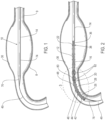
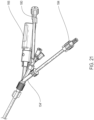
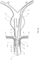
- FIGS. 1-12 an embodiment of a delivery system 10 for treatment of a vascular defect such as aneurysm 8 is shown in FIGS. 1-12 .
- a vascular defect such as aneurysm 8
- FIGS. 1-12 an embodiment of a delivery system 10 for treatment of a vascular defect such as aneurysm 8
- the exemplary aneurysm 8 shown in the patient's vasculature 9 is a thoracic type aortic aneurysm
- devices and methods as discussed herein and illustrated in the corresponding figures may also be used for any other suitable type of vascular defect such as abdominal aortic aneurysms (shown in FIG. 1A ) and the like.
- the delivery system embodiment 10 may include an endoluminal prosthesis 12 for treatment of the vascular defect 8 and a delivery catheter 14.
- the endoluminal prosthesis may include a tubular main graft portion 16 made from a thin flexible material, and including a main inner lumen 18, a proximal end 20 and a distal end 22.
- the graft body may be formed from a flexible and supple graft material, such as PTFE, and have a main fluid flow lumen disposed in a main graft portion therein.
- flexible graft material including PTFE may include expanded PTFE or ePTFE.
- the endoluminal prosthesis 12 may also have a self-expanding anchor member 24 that has a proximal portion 26 and a distal portion 28 with a distal end of the distal portion being secured to a proximal end 20 of the tubular main graft portion and a distal end of the proximal portion being secured to a proximal end of the distal portion.
- the self-expanding anchor member embodiment 24 shown in FIG. 2 has a generally cylindrical configuration with a free unsecured end at a proximal end thereof and a distal end that is secured to a proximal end of the main graft body.
- the proximal portion 26 of the self-expanding anchor member 24 may include a cylindrical stent including an elongate superelastic element disposed in a zig-zag configuration and the distal portion of the self-expanding anchor member comprises a cylindrical stent including an elongate superelastic element disposed in a zig-zag configuration.
- An optional connector ring (not shown) may be embedded into the structure of the proximal end of the main graft portion and may be coupled to the distal end of the proximal self-expanding anchor member 24. In some cases, such a connector ring may include a self-expanding zig-zag shaped made from a superelastic material such as a nickel titanium alloy.
- the deployment assistance provided by the inflatable balloon due to the outward radial force supplied by the inflatable balloon may be particularly useful in endoluminal prosthesis embodiments that do not include a self-expanding connector ring.
- a connector ring may be useful to provide an opening force at the proximal end of the graft portion of the endoluminal prosthesis during deployment.
- the proximal self-expanding anchor member 24, including a proximal portion and distal portion thereof, may have a monolithic structure with the proximal portion and distal portion both formed from a single piece of continuous material with no joints formed between the portions.
- embodiments of the self-expanding anchor member 24 may be made from a superelastic metal, including superelastic metals such as nickel titanium alloys.
- the proximal self-expanding anchor member 24 may include outwardly extending barbs (not shown), that may be integrally formed with struts of the stent structure of either or both the proximal portion 26 and distal portion 28 of the self-expanding anchor member 24.
- Such barbs may have sharp or sharpened tissue penetrating tips configured to penetrate into tissue of an inside surface 30 of a lumen within which the proximal self-expanding anchor member 24 may be deployed in an expanded state.
- Such a barb configuration may be used to facilitate securement of the self-expanding anchor member 24 to the inner surface 30 of the patient's vasculature 9 or other luminal surface.
- the self-expanding anchor members discussed herein may include a proximal portion and a distal portion, other embodiments may be used.
- similar expanding anchor members may be used that are configured to be inelastically expanded with outward radial pressure as might be generated by the expansion of a radially expandable inflatable balloon from within either or both the proximal portion and distal portion of the proximal self-expanding anchor member.
- Such inelastically expandable anchor members may otherwise have the same features, dimensions and configurations as those of the self-expanding anchor members discussed herein.
- the endoluminal prosthesis 12 may also have a plurality of radiopaque markers 32 which are circumferentially disposed about a tubular configuration of the endoluminal prosthesis 12 adjacent the proximal end 20 of the tubular main graft portion.
- the plurality of radiopaque markers 32 may be substantially equally spaced around a circumference of a tubular portion of the endoluminal prosthesis 12 and all lie in a common plane which is substantially perpendicular to a longitudinal axis 34 of the proximal self-expanding anchor member and main graft portion of the endoluminal prosthesis 24.
- the radiopaque markers 32 may be disposed around a circumference of the self-expanding anchor member 24 at a distal end of the self-expanding anchor member 24. Such an arrangement may be useful in visualizing the alignment of the endoluminal prosthesis during the deployment process.
- Some endoluminal prosthesis embodiments may include about 4 to about 12, more specifically, about 5 to about 8, such circumferentially spaced radiopaque markers 32 lying in a common plane, the common plane optionally being perpendicular to a longitudinal axis 34 of the main graft portion of the endoluminal prosthesis.
- the delivery catheter 14 of the delivery system 10 may include an elongate shaft 36 with sufficient column strength for percutaneous advancement within a patient's vasculature 8, the elongate shaft 36 also having a proximal section 38 and a distal section 40.
- a plurality of releasable belts may be disposed on the proximal section 38 of the elongate shaft 36 and configured to releasably constrain a self-expanding anchor member of an endoluminal prosthesis.
- a plurality of appropriately sized cylindrical bushings or pads 33 may be secured over the elongate shaft adjacent one or more of the releasable belts in order to properly space the self-expanding anchor member 24 or portions thereof while in a constrained state.
- a plurality of elongate release members may be disposed in operative communication with a distal section of the elongate shaft 36 and said elongate release members may each include a proximal section configured to releasably secure at least one respective releasable belt while said releasable belt is in a configuration that constrains at least a portion of the self-expanding anchor member 24 of the endoluminal prosthesis 12.
- the plurality of releasable belts configured to releasably constrain the proximal self-expanding anchor member 24 of the endoluminal prosthesis 10 may be secured along the proximal section 38 of the elongate shaft 36.
- a first proximal releasable belt 42 and second proximal releasable belt 44 are secured about the proximal portion 26 of the self-expanding anchor member 24.
- a first distal releasable belt 46 and second distal releasable belt 48 are secured about the distal portion 28 of the self-expanding anchor member 24.
- first elongate release member 50 and second elongate release member 52 may extend to and be in communication with a distal end of the elongate shaft 36.
- first elongate release member 50 and second elongate release member 52 may extend to and be in communication with a distal end of the elongate shaft 36.
- three or more release wires may be used.
- an additional release wire (not shown) may be used to provide a releasable interlock for a connection or coupling between a fill tube 69 and inflatable portion of an inflatable embodiment of the endoluminal prosthesis 12.
- the first release member 50 and second release member 52 may have a proximal section configured to releasably secure at least one respective releasable belt, such as the first proximal releasable belt 42, second proximal releasable belt 44, first distal releasable belt 46, or second distal releasable belt 48, while the releasable belts are in a configuration that constrains at least a portion of the endoluminal prosthesis 10, such as the proximal self-expanding anchor member 24.
- the release members 50, 52 may be configured to deploy the self-expanding anchor member 24 at a proximal end of the endoluminal prosthesis 12.
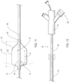
- a first release wire 50 shown is coupled to the first proximal releasable belt 42 and the second proximal releasable belt 44 and can thereby be used to deploy the first proximal releasable belt 42 and second proximal releasable belt 44 (in that order) by distally retracting the first release member 50 by a mechanism in a distal adapter 54 (shown in FIG. 12 ) or any other suitable method.
- the second release member 52 shown is coupled to the first distal releasable belt 46 and the second distal releasable belt 48 and can thereby be used to deploy the first distal releasable belt 46 and second distal releasable belt 48 (in that order) by distally retracting the second release member 52 by a mechanism in a distal adapter 54 or any other suitable method.
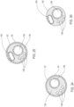
- a delivery catheter embodiment 14 may include an elongate shaft 36 with one or more release member lumens 58 extending within a release member sleeve 67, a guidewire lumen 56 extending within a guidewire tube 57 for passage of a guidewire 49, an inflation lumen 60 for inflation of an inflatable balloon 62 extending within an inflation tube 61 and an optional fill lumen 64 for filling an optional inflatable portion of the endoluminal prosthesis 12 extending within a fill tube 69.
- the section of the elongate shaft 36 of the delivery catheter embodiment 14 shown in FIG. 5 illustrates the release member lumens 58 and guidewire lumen 56, surrounded by guidewire tube 57.
- the section in FIG. 4 also includes the inflation lumen 60 surrounded by the inflation tube 61.
- the inflation tube 61 may have an inflation lumen 60 with a substantially round inner transverse section, for other embodiments, the inflation lumen 60 may have a transverse section that is oval in shape.
- the round inflation lumen embodiments may have an inner diameter of about 0.01 inches to about 0.03 inches, more specifically, about 0.014 inches to about 0.016 inches, 0.01 inches to about 0.02 inches, 0.02 inches to about 0.025 inches, about 0.015 inches, or any other suitable inner diameter.
- Some oval inflation lumen embodiments 60 may have a major inner transverse dimension of about 0.055 inches to about 0.060 inches, and a minor inner transverse dimension of about 0.024 inches to about 0.028 inches.
- Inflation tube lumen embodiments 61A, 61A' and 61A" shown in FIGS. 27-33 are configured to accommodate respective inflation tubes 61 and 61'.
- Each of these lumen embodiments 56, 58, 60 and 64 and tube or sleeve embodiments 57, 61, 67 and 69 may extend axially along or within the elongate shaft 36 of the delivery catheter 14 from a proximal section to a distal end thereof, including to the distal adapter 54 at the distal end of the elongate shaft 36.
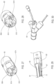
- the release members may be coupled to respective deployment knobs 66 disposed on the distal adapter 54 shown in FIG. 12 .
- the inflatable balloon 62 which may be integrally formed with the elongate shaft 36 may be operatively secured to the elongate shaft 36 of the delivery catheter 14 within the main inner lumen 18 (shown in FIG. 7 ) of the tubular main graft portion 16 of the endoluminal prosthesis 12. According to the invention, the inflatable balloon 62 may be disposed in an axial position wherein a proximal end 68 of an inflatable section 55 of the inflatable balloon 62 is positioned adjacent but distal of the radiopaque markers 32.
- the inflatable balloon 62 may be disposed within a non-deployed constrained endoluminal prosthesis 12 in an axial position with the proximal end 68 of the inflatable section 55 of the inflatable balloon 62 disposed adjacent but distal of the self-expanding anchor member structure such as a self-expanding anchor member 24 as shown in FIGS. 3 , 9 and 10 .
- the inflatable section 55 of the inflatable balloon 62 may also be disposed with a proximal end 68 of the inflatable section 55 thereof disposed adjacent but distally of any other high strength resilient structures that may be associated with securing an anchor member portion of an endoluminal prosthesis 12 to a main graft portion 16 of an endoluminal prosthesis 12, such as a connector ring.
- the inflatable section 55 of the inflatable balloon 62 may be axially positioned so as to fail to axially overlap or lie in the same horizontal plane as the self-expanding anchor member 24 or any other high strength structure associated with the self-expanding anchor member 24.
- the proximal end 68 of the inflatable section 55 of the inflatable balloon 62 may be said to be adjacent but distal of a structure such as the radiopaque markers 32 or self-expanding anchor member 24 if an optional axial gap between these respective elements is up to about 5 mm, more specifically, up to about 2 mm, for some embodiments.
- FIGS.3 , 10 and 23 show an example of such an optional axial gap as indicated by arrows 55'.
- FIGS. 3 and 10 illustrate the optional axial gap between the proximal end 68 of the inflatable section 55 of the inflatable balloon 62 and a distal most portion of the radiopaque markers 32.
- FIG. 3 and 10 illustrate the optional axial gap between the proximal end 68 of the inflatable section 55 of the inflatable balloon 62 and a distal most portion of the radiopaque markers 32.
- FIG. 23 illustrates an optional gap 55' disposed between the proximal end of the inflatable section 55 of the inflatable balloon 62 and a distal most end of both the radiopaque markers 132 and distal most end of the self-expanding anchor member 124.
- the shaped tubular wall material of the inflatable balloon 62 may be secured or bonded to the elongate shaft 36 in a neck portion by adhesive such as ultraviolet cured adhesives, laser bonding or welding, thermal bonding or welding, or any other suitable method.
- adhesive such as ultraviolet cured adhesives, laser bonding or welding, thermal bonding or welding, or any other suitable method.
- the balloon shaft section 59 of the elongate shaft 36 may include a substantially tubular portion of the elongate shaft 36 extending axially within the inflatable balloon 62 and include an outer surface suitable for bonding of the balloon 62 and providing a fluid tight barrier for the interior volume of the inflatable balloon 62.
- some embodiments may include a balloon shaft section 59 and inflatable balloon 62 which are both made from polyurethane.
- a proximal neck portion 63 of some inflatable balloon embodiments 62 may be positioned proximal the radiopaque markers 32 and/or self-expanding anchor member 24 so long as the proximal angled portion or proximal cone of the inflatable balloon 62 and any pleats of the inflatable balloon 62 are disposed distal to the radiopaque markers 32 and/or self-expanding anchor member 24.
- the proximal neck portion 63 is a portion of a tubular member of the inflatable balloon 62 which is in contact with an outer surface of the elongate shaft 36 and typically is where the proximal end of the inflatable balloon 62 is bonded to the elongate shaft 36.
- the distal end of the inflatable balloon 62 is similarly bonded to the elongate shaft 36 over a distal neck portion 63'.
- These bonded portions 63 and 63' may have a length that is selected to provide the necessary bond strength to support a desired inflation pressure while minimizing a length of the bonded portion in order to reduce the amount of material and overall profile of the delivery system 10.
- the proximal neck portion 63 and distal neck portion 63' may have an axial length of at least about 4 mm, more specifically, about 4 mm to about 8 mm.
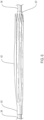
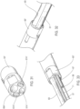
- the inflatable balloon 62 may be formed into a pleated configuration while in an uninflated state in order to keep the uninflated profile of the inflatable balloon 62 to a minimum.
- inflatable balloon embodiments 62 may be machine folded (or folded by any other suitable means) to include about 5 pleats to about 10 pleats, more specifically, about 6 pleats to about 8 pleats, as shown in FIG. 6 .
- the distal ends of the pleats may be folded over a distal neck portion 63' of the inflatable balloon 62 in order to shift some of the bulk of the inflatable balloon while in an uninflated state away from the structure of the radiopaque markers 32 and/or self-expanding anchor member 24.
- both a working length and overall length of the inflatable balloon 62 may be considered.
- the working length extends along a full diameter length portion of the inflatable balloon 62 where an outer surface of the inflatable balloon 62 is configured to contract and apply outward pressure onto an inside surface of the endoluminal prosthesis 12 when the inflatable balloon is in an inflated state.
- the overall length includes all of the inflatable section 55 including the tapered conical type sections at one or both ends of the inflatable balloon 62.
- the working length of the inflatable balloon 62 is indicated by arrow 51 and the overall length of the inflatable balloon 62 is indicated by arrow 53 in FIG. 11 .
- the inflatable balloon 62 may include an outer transverse dimension/diameter of about 10 mm to about 26 mm and a working length of about 15 mm to about 50 mm, more specifically, about 15 mm to about 40 mm. Some embodiments may include a working length of about 15 mm to about 25 mm, more specifically, about 18 mm to about 22 mm. In some cases, inflatable balloon embodiments 62 made from a substantially non-compliant material may have an outer diameter of about 26 mm for use with an endoluminal prosthesis 12 having a tubular main graft portion with an inner lumen diameter of about 26 mm.
- Some inflatable balloon embodiments 62 made from a substantially non-compliant material may have an outer diameter of about 15 mm to about 22 mm and an axial length of about 16 mm to about 20 mm for use with endoluminal prosthesis embodiments 12 having a main graft portion with an inner lumen diameter of about 15 mm to about 22 mm.
- an inflatable balloon 62 made from a compliant material having an outer diameter of about 16 mm to about 19 mm and working length of about 16 mm to about 20 mm may be used with delivery system embodiments 10 having an endoluminal prosthesis 12 with a main graft portion with an inner lumen diameter of about 26 mm.
- Some inflatable balloon embodiments 62 may have a working length of about 18 mm to about 21 mm, an overall length of about 32 mm to about 38 mm, and an outer diameter of about 15 mm to about 26 mm. Some embodiments of the inflatable balloon 62 may be made from a compliant material with an outer diameter of about 16 mm to about 20 mm, a working length of about 16 mm to about 20 mm and an overall length of about 32 mm to about 38 mm. Such an inflatable balloon embodiment 62 may be used in some cases with an endoluminal prosthesis 12 having an inner lumen diameter of about 15 mm to about 26 mm.
- the proximal end surface 70 of the balloon 62 may be relatively flat or have a cone angle that is close to 180 degrees.
- the inflatable balloon 62 may have a proximal end surface 70 with a cone angle 72 (as shown in FIG. 11 ) of about 160 degrees to about 180 degrees.
- a cone angle 72 of about 120 degrees to about 160 degrees, more specifically, about 125 degrees to about 135 degrees.
- Some embodiments may have a cone angle 72 of about 80 degrees, to about 120 degrees, more specifically, about 80 degrees to about 100 degrees, and even more specifically, of about 90 degrees to about 98 degrees.
- a wall material of the inflatable balloon 62 may include a compliant material and for other embodiments the wall material of the inflatable balloon 62 may include a substantially non-compliant material. Some inflatable balloon embodiments 62 may also include a laminate structure with multiple layers of material that may include both compliant and substantially non-compliant materials. In some cases, the wall material of the inflatable balloon 62 may include a material such as polyethylene terephthalate (PET), polyamides such as Nylon ® , polyether block amides such as Pebax ® , polyethylene (PE), polyurethane (PU) and polyvinylchloride (PVC) or the like or any combination thereof.
- PET polyethylene terephthalate
- polyamides such as Nylon ®
- polyether block amides such as Pebax ®
- PE polyethylene
- PU polyurethane
- PVC polyvinylchloride
- any of the inflatable balloon embodiments discussed herein may include a double wall thickness of the balloon material of about 0.001 inches to about 0.003 inches.
- Some inflatable balloon embodiments 62 may have a double wall thickness of about 0.0005 inches to about 0.002 inches, more specifically, about 0.00075 inches to about 0.0015 inches.
- a double wall thickness is a measurement derived from measuring a thickness of two thicknesses of the wall of the inflatable balloon 62. In this way, the wall thickness of an inflatable balloon 62 may be measured while keeping the inflatable balloon 62 intact.
- the delivery catheter 14 may have an outer sheath 74 with an elongate tubular shape and thin wall which is disposed over the elongate shaft 36 and endoluminal prosthesis 12.
- the outer sheath 34 may be configured to slide over the relative to the elongate shaft and endoluminal prosthesis so as to removably cover the endoluminal prosthesis 12 while in a constrained state.
- the delivery catheter 14 may also include a proximal nosecone 76 which may have a bullet-shaped profile and a shoulder portion having an outer surface which may be configured to slidingly accept an inner luminal surface of the retractable outer sheath 74.
- the delivery system and method embodiments 10 discussed herein may be particularly useful for endoluminal prosthesis embodiments 12 which include one or more inflatable portions.
- inflatable endoluminal prosthesis embodiments 12 that may be deployed by the systems and methods discussed herein are discussed in U.S. Patent No. 7,147,660 filed by M. Chobotov et al. on December 20, 2002 , titled “Advanced Endovascular Graft” which is hereby incorporated by reference herein in its entirety.
- an optional inflatable portion 80 of the graft portion 16 of the endoluminal prosthesis may include one or more inflatable cuffs 82 and/or one or more inflatable channels (not shown) formed from the flexible material of the main graft portion and legs 84 (see the bifurcated legs shown in the embodiment of FIG. 34 ).
- the inflatable cuffs 82 are disposed on a proximal portion of the main graft portion 16.
- a fill tube 69 may also be configured to be coupled to and in fluid communication with a distal end of a fill port 88 (shown in FIG. 9 ) of the inflatable portion 80 of the endoluminal prosthesis 12. The fill tube 69 may also be uncoupled from the inflation port 88.
- the fill tube's outer transverse dimension may be configured to slide within an inner lumen of the fill port 88 and provide a seal there between for viscous fluids.
- the delivery catheter 14 may include the fill tube 69 including the fill lumen 64 extending axially within the elongate shaft 36 from a proximal section to a distal section of the elongate shaft 36.
- delivery system embodiments 10 discussed herein may include a delivery catheter 14 with an endoluminal prosthesis 12 such as a stent graft in a radially constrained state releasably disposed on a proximal section 38 of the delivery catheter 14.
- a delivery catheter 14 may include some or all of the features, dimensions or materials of delivery systems discussed in commonly owned U.S. Patent Application Publication No. 2004/0138734, published July 15, 2004, filed October 16, 2003, by Chobotov et al. , titled “Delivery System and Method for Bifurcated Graft” and in PCT International Publication No. WO 02/083038, published October 24, 2002, filed April 11, 2001, by Chobotov et al. , titled “Delivery System and Method for Bifurcated Graft” each of which is incorporated by reference herein in its entirety.
- the endoluminal prosthesis 12, or any other prosthesis discussed herein may include some or all of the features, dimensions or materials of the prostheses discussed in commonly owned U.S. Patent Publication No. 2009/0099649, filed October 3, 2008, by Chobotov et al. , titled Modular Vascular Graft for Low Profile Percutaneous Delivery, which is incorporated by reference herein in its entirety.
- the portion of the endoluminal prosthesis 12 may include radiopaque markers 32 (such as circumferentially disposed radiopaque markers lying in a common plane) in order to accurately visualize the partially deployed stent graft 12 prior to full deployment of the stent graft.
- radiopaque markers 32 such as circumferentially disposed radiopaque markers lying in a common plane
- Such a deployment protocol may be particularly useful for endoluminal prosthesis embodiments 12 such as stent grafts that do not include a connector ring structure in a proximal end of the graft portion 16 of the stent graft 12. This is because a self-expanding type connector ring may be useful in some cases to assist with outward radial expansion of the proximal end or flap of the graft portion of the stent graft after the distal portion of the proximal self-expanding anchor member 24 has been released.
- the proximal end or flap 20 of the graft portion 16 of the stent graft may only open about 10 mm or so which may not be conducive to accurate imaging and positioning using observation of parallax of the radiopaque markers 32 during deployment.
- deploying an endoluminal prosthesis 12 may include advancing a delivery system 10 into a patient's vasculature which includes an elongate shaft 36 and an endoluminal prosthesis 12 releasably secured to the elongate shaft 36.
- the method may also include releasing an outer constraint from a graft portion 16 of the endoluminal prosthesis 12 such as by retracting the outer sheath 74 of the delivery catheter 14.
- An outer radial constraint may then be partially released from the self-expanding anchor member 24 of the endoluminal prosthesis 12 (as shown in FIG.
- the inflatable balloon 62 may be inflated and radially expanded so as to radially expand a portion of a graft portion 16 of the endoluminal prosthesis 12 which is disposed adjacent the inflatable balloon 62.
- the inflatable balloon 62 may be is disposed within a main inner lumen 18 of the graft portion 16 of the endoluminal prosthesis 12 with a proximal end of the inflatable balloon 62 being disposed adjacent but distal of the self-expanding anchor member 24.
- the inflatable balloon 62 may be is disposed within a main inner lumen 18 of the graft portion 16 of the endoluminal prosthesis 12 with a proximal end of the inflatable balloon 62 being disposed adjacent but distal of a plurality of radiopaque markers 32 which may be circumferentially disposed adjacent a proximal edge 20 of the graft portion of the endoluminal prosthesis 12.
- An outer radial constraint on the self-expanding anchor member 24 may then be fully released so as to fully deploying the self-expanding anchor member 24 of the endoluminal prosthesis 12.
- inflating and radially expanding the inflatable balloon 62 may include inflating and radially expanding the inflatable balloon 62 so as to apply an outward radial force onto an inner surface of a main inner lumen 18 of a graft portion 16 of the endoluminal prosthesis 12 until an outer surface of the graft portion 16 adjacent the inflatable balloon 62 is urged into contact with an inner surface of the patient's vasculature 8.
- the saline or other inflation fluid may then be injected through the inflation lumen 60 of the elongate shaft 36 and enter an interior volume of the inflatable balloon 62 at the desired pressure.
- inflating the inflatable balloon 62 includes inflating the interior volume of the inflatable balloon 62 with a sterile incompressible fluid such as saline at a pressure of about 3 psi to about 9 psi and in some cases to a pressure of up to about 1 atmosphere within the inflation lumen 60.
- a sterile incompressible fluid such as saline at a pressure of about 3 psi to about 9 psi and in some cases to a pressure of up to about 1 atmosphere within the inflation lumen 60.
- the pressurized saline may be injected with a device such as an Endoflator ® or standard syringe by coupling the inflation device to a connector such as a Luer type connector on the distal adapter 54.
- the interior volume of the inflatable balloon 62 may be inflated with a mixture of saline and contrast media in order to improve the ability to image the inflated or partially inflated inflatable balloon 62 using fluoroscopy or the like.
- a mixture of about 25% contrast media and about 75% saline may be used, in other embodiments, a mixture of about 20% contrast media and about 80% saline may be used.
- the interior volume of the inflatable balloon 62 may be about 6 ml to about 20 ml.
- the endoluminal prosthesis 12 may be axially repositioned within the patient's vessel 9 after partially deploying the self-expanding anchor member 24 and before fully deploying the self-expanding anchor member 24. In such cases, it may be desirable to deflate the inflatable balloon 62 prior to repositioning the endoluminal prosthesis 12.
- the working length (as indicated by arrows 51) of the inflatable balloon 62 may also be desirable for the working length (as indicated by arrows 51) of the inflatable balloon 62 to be positioned axially coextensively with the inflatable cuffs 82.
- the outward radial force imposed by the outer surface of the inflatable balloon 62 upon inflation may be useful in order to assist with sealing and apposition of one or more inflatable cuffs 82 against an inner luminal surface of the patient's vasculature 9.
- the inflatable balloon 62 may be used to expand one or more inflatable cuff embodiments 82 in an outward radial direction without similarly expanding the self-expanding anchor member 24.
- an inflatable balloon 62 as discussed herein that is disposed within the endoluminal prosthesis 12 such that the inflatable balloon 62 is disposed so as to be axially coextensive and axially overlapping a first inflatable cuff 82 but not be axially coextensive or axially overlap a second inflatable cuff 82 of the same endoluminal prosthesis 12.
- deployment devices, alignment devices, radiopaque markers 32, delivery methods and the like that may be used in conjunction with any suitable system or component thereof discussed herein may be found in commonly owned U.S. Patent Application No. 2011/0218609, filed February 9, 2011, by M. Chobotov et al. , and titled "Fill Tube Manifold and Delivery Methods for Endovascular Graft", and U.S. Patent Publication No.
- 2013/0268048 filed March 15, 2013, by J. Watson et al. , and titled “Delivery Catheter for Endovascular Device", U.S. Patent Publication No. 2013/0268044, filed March 13, 2013, by D. Parsons et al. , and titled “Durable Stent Graft with Tapered Struts and Stable Delivery Methods and Devices", each of which is hereby incorporated by reference herein in its entirety.
- embodiments of the inflatable balloon 62 may have an axial length of about 25 to about 27 mm and a transverse diameter of about 16 mm to about 18 mm when in an inflated state. Such an inflatable balloon 62 may be inflated through an inflation lumen 60 having an inner transverse lumen diameter of about 0.014 inches to about 0.016 inches.
- the inflatable balloon 62 may be made from a compliant material such as urethane with an outer diameter of about 25 mm to about 26 mm and an axial length of about 25 mm.
- An inflatable balloon 62 so sized may be useful for delivery of an endoluminal prosthesis 12 having an inner lumen diameter of 26 mm (including an Ovation ® type stent graft device manufactured by TriVascular, Inc., Santa Rosa, CA).
- the inflatable balloon 62 may be bonded or otherwise secured to the elongate shaft 36 close to a proximal end or proximal flap 20 of the main graft section 16 of the endoluminal prosthesis 12 with an ultraviolet cured adhesive.
- An axial length of about 25 mm for the inflatable balloon 62 may be sufficient in some embodiments to allow the inflatable balloon 62 to axially overlap the inflatable cuffs 82 disposed at a distal section of the graft section 16 of the endoluminal prosthesis 12.
- the proximal end face 70 of the balloon embodiment may be flat (that is, with a cone angle 72 of about 180 degrees) or even overhanging.
- the inflation lumen 60 for the inflatable balloon 62 may be made from a thin walled material such as polyimide with an inner lumen diameter of about 0.01 inches to about 0.02 inches to enable filling of the inflatable balloon 62 in a few seconds, such as about 15 seconds, using high flow fluids such as saline or the like.
- the inflation lumen 60 may have an inner lumen diameter of about 0.020 inches to about 0.025 inches to enable quicker filling and inflation of the inflatable balloon 62.
- the inflation of such an inflatable balloon embodiment 62 may be carried out with a syringe (not shown) connected to a Luer type fitting on the distal adapter 54.
- the inflatable balloon 62 may be inflated by hand with a syringe or the like. In some cases, the inflatable balloon 62 may be initially inflated to an outside dimension or diameter of about 8 mm prior to release of this release wire 52. In some cases, the inflatable balloon 62 may be inflated until the proximal end or proximal flap 20 of the graft portion 16 of the endoluminal prosthesis 12 and radiopaque markers 32 disposed adjacent thereto are radially expanded in an outward direction almost to an inner surface of the wall of the vessel 9 being treated.
- the inflatable balloon 62 may be inflated to an outer transverse dimension or diameter of about 15 mm after release of this release wire 52. After accurately positioning the endoluminal prosthesis 12 in an axial direction with respect to the patient's renal arteries 92 (or any other suitable reference point) the other release wire 50 may be retracted and the proximal self-expanding anchor member fully deployed.
- the inflatable balloon 62 may then be deflated prior to inflating an optional inflatable portion 80 of the endoluminal prosthesis 12.
- the inflatable portion 80 of the endoluminal prosthesis 12 may be inflated while the inflatable balloon 62 is still inflated.
- the fill tube 69 may be demated and the elongate shaft 36 of the delivery catheter 14 withdrawn in a distal direction from within the endoluminal prosthesis 12.
- Using the inflatable balloon 62 to apply outward radial force on the graft portion 16 of the endoluminal prosthesis 12 during deployment may also be useful in eliminating type I endoleaks if present during the deployment process. This may be particularly true for embodiments that include optional inflatable cuffs 82 on the graft portion 16 of the endoluminal prosthesis 12.
- the inflatable portion 80 of the endoluminal prosthesis 12 remains coupled to the fill tube 69 for a predetermined amount of time after initiation of fill of the inflatable portion 80 with a fill material such as a polymerizable or curable fill material.
- the inflatable balloon 62 may then be positioned across both optional inflatable cuffs 82 and inflated to a suitable inflation pressure such as about 3 psi to about 6 psi.
- the predetermined amount of elapsed time prior to inflating the inflatable balloon to expand the filled cuffs 82 in an outward radial direction may be about 14 minutes, in some instances, exactly 14 minutes. Such a procedure may be useful to resolve endoleaks. Once resolved, or other appropriate end point is achieved, the inflatable balloon 62 may be deflated and the fill tube 69 demated from the fill port of the inflatable portion 80 of the endoluminal prosthesis 12.
- an endoluminal prosthesis 12 in the form of a stent graft having a graft portion 16 with an inner diameter of about 29 mm when in an expanded state and proximal self-expanding anchor member 24 having an outer diameter of about 34 mm when in an expanded state may be loaded into a delivery catheter having an outer sheath with an outer diameter of about 15 French. This combination resulted in an outer sheath retraction force of about 18 pounds for unsheathing movement of the outer sheath 74.
- the radial expansion achieved after release of the distal portion of the proximal self-expanding anchor member 24 and initial inflation of the balloon was from about 10 mm to about 17 mm x about 11 mm.
- the inflatable balloon 62 also had a tapered configuration that ultimately achieved an inflated dimension of about 20 mm outer diameter and an axial length of about 7mm. This inflatable balloon took about 1 minute to fill through an inflation lumen 60 having an inner diameter of about 0.015 inches.
- the delivery catheter 14 did not include a crossover lumen.
- an endoluminal prosthesis 12 in the form of a stent graft having a graft portion 16 with an inner diameter of about 26 mm when in an expanded state and proximal self-expanding anchor member 24 having an outer diameter of about 34 mm when in an expanded state may be loaded into a delivery catheter 14 having an outer sheath 74 with an outer diameter of about 15 French.
- This combination resulted in an outer sheath retraction force of about 7 pounds for unsheathing movement of the outer sheath 74.
- the radial expansion achieved after release of the distal portion 28 of the proximal self-expanding anchor member 24 and initial inflation of the balloon 62 was from about 10 mm to about 25 mm.
- the inflatable balloon 62 also had a tapered configuration that ultimately achieved an inflated dimension of about 20 mm outer diameter and an axial length of about 7mm. This inflatable balloon took about 16 seconds to fill about 5 ml of saline through an inflation lumen 60 having an inner diameter of about 0.02 inches by hand injection.
- the delivery catheter 14 did not include a crossover lumen.
- an endoluminal prosthesis 12 in the form of a stent graft having a graft portion 16 with an inner diameter of about 26 mm when in an expanded state and proximal self-expanding anchor member 24 having an outer diameter of about 34 mm when in an expanded state may be loaded into a delivery catheter 14 having an outer sheath 74 with an outer diameter of about 15 French. This combination resulted in an outer sheath retraction force of about 9 pounds for unsheathing movement of the outer sheath 74.
- the radial expansion achieved after release of the distal portion of the proximal self-expanding anchor member 24 and initial inflation of the balloon 62 was from about 10 mm to about 19 mm and ultimately to about 25 mm at maximum inflation.
- the inflatable balloon 62 also had a tapered configuration that ultimately achieved an inflated dimension of about 20 mm outer diameter and an axial length of about 7mm. This inflatable balloon took about 15 seconds to fill about 6 ml of saline through an inflation lumen having an inner diameter of about 0.025 inches by hand injection.
- the delivery catheter 14 did include a crossover lumen, a fill port at the distal adapter 54 and retraction of the balloon 62 during the procedure was acceptable.
- an endoluminal prosthesis 12 in the form of a stent graft having a graft portion 16 with an inner diameter of about 26 mm when in an expanded state and proximal self-expanding anchor member 24 having an outer diameter of about 34 mm when in an expanded state may be loaded into a delivery catheter 14 having an outer sheath 74 with an outer diameter of about 14 French.
- This combination resulted in an outer sheath retraction force of about 13 pounds for unsheathing movement of the outer sheath 74.
- the radial expansion achieved after release of the distal portion of the proximal self-expanding anchor member 24 and initial inflation of the balloon 62 was from about 10 mm to about 20 mm.
- the inflatable balloon 62 also had a standard configuration that ultimately achieved an inflated diameter of about 15 mm and an axial length of about 25 mm. This inflatable balloon was filled through an inflation lumen having an inner diameter of about 0.025 inches.
- the delivery catheter 14 did include a crossover lumen 71 and a fill port at the distal adapter 54. This particular example was used in conjunction with a chimney type graft 90 (6 mm Viabahn ® graft manufactured by Gore Enterprises, Flagstaff, AZ) and a compliant Coda ® balloon model 32 mm, manufactured by Cook Medical located in Bloomington Indiana, during the fill and no gutter type channels were observed with the Coda balloon inflated or when deflated.
- an endoluminal prosthesis 12 in the form of a stent graft having a graft portion 16 with an inner diameter of about 22 mm when in an expanded state and proximal self-expanding anchor member 24 having an outer diameter of about 29 mm when in an expanded state may be loaded into a delivery catheter 14 having an outer sheath 74 with an outer diameter of about 14 French.
- This combination resulted in an outer sheath retraction force of about 15 pounds for unsheathing movement of the outer sheath 74.
- the radial expansion achieved after release of the distal portion of the proximal self-expanding anchor member 24 and initial inflation of the balloon 62 was from about 8 mm to about 21 mm.
- the inflatable balloon ultimately achieved an inflated diameter of about 10 mm and an axial length of about 15 mm.
- This inflatable balloon 62 was filled through an inflation lumen 60 having an inner diameter of about 0.025 inches to an inflation pressure of about 6 psi with water.
- the delivery catheter 14 did include a crossover lumen 71 and a fill port at the distal adapter 54. This particular example was used in conjunction with a chimney type graft 90 (5 mm tygon type tubing) and a non-compliant balloon 62 and during the fill a good seal was made after demate of the fill tube 69.
- Some endoluminal prosthesis embodiments 12 may include a graft portion 16 with an inner diameter of about 26 mm when in an expanded state and proximal self-expanding anchor member 24 having an outer diameter of about 34 mm when in an expanded state. Such an endoluminal prosthesis 12 may be loaded into a delivery catheter 14 having an outer sheath 74 with an outer diameter of about 15 French.
- the inflatable balloon 62 for this embodiment may be made from polyurethane with a durometer of about 90A and a double wall thickness of 0.001 inches.
- the inflatable balloon may include an outer diameter of about 18.5mm, a working length of about 20mm and an overall length of about 38mm.
- the inflatable balloon cone angle may be about 46 to about 48 degrees on each side for a full cone angle 72 of about 92 degrees to about 96 degrees.
- the elongate shaft 36 may be made from a polyurethane material with a durometer of about Shore 72D.
- the elongate shaft 36 may further have an outer diameter of about 0.105 inches and extend an entire axial length of the endoluminal prosthesis 12. Such an embodiment may yield a retraction force for the outer sheath 74 of about 11 pounds for unsheathing movement of the outer sheath 74.
- the radial expansion achieved after release of the distal portion of the proximal self-expanding anchor member 24 and initial inflation of the balloon 62 may be from about 8 mm to about 20 mm with an interior volume of the inflatable balloon 62 partially inflated to about 10ml.
- Such an inflatable balloon embodiment 62 may ultimately achieve an inflated diameter of about 26mm, which may be consistent with the inner lumen size of the associated endoluminal prosthesis, when filled to its maximum inflation volume of about 19ml.
- This inflatable balloon 62 may be filled through an oval inflation lumen 60 having a minor inner transverse of about 0.025 inches and a major inner transverse dimension of about 0.055 inches.
- Inflation of such an inflatable balloon embodiment 62 may take about 18 seconds to fill about 19 ml of 4 to 1 saline to contrast mixture through the inflation lumen by hand injection.
- the corresponding delivery catheter 14 may include a crossover lumen 71 and a fill port at the distal adapter 54.
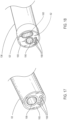
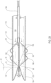
- any of the inflatable balloon embodiments discussed herein it may be desirable to include means (shown in FIGS. 13 and 14 ) for allowing blood perfusion past the inflatable balloon 62 while the inflatable balloon 62 is in an inflated state.
- This may be applicable for indications that include treatment of thoracic aortic aneurysms and abdominal aortic aneurysms. This may be particularly true for the larger thoracic aorta where such perfusion means including perfusion holes, a flower petal shape inflatable balloon 62' as shown in FIG. 13 or multiple small inflatable balloons 62" as shown in FIG. 14 bunched together may be useful to avoid migration of the endoluminal prosthesis during deployment as well as allowing blood flow during inflation.
- the number of flower petal shape inflatable balloons 62' or multiple small inflatable balloons 62" disposed about the shaft 36 may be about 3 to about 5 balloons 62".
- FIGS. 15-26 illustrate embodiments of delivery systems for treatment of a vascular defect such as aneurysm 8.
- the delivery system embodiment 110 may include the endoluminal prosthesis 12 for treatment of the vascular defect 8 and a delivery catheter 114.
- the delivery system 110 may include the same or similar materials, dimensions and features as those of the delivery system 10 discussed above. Where appropriate, like reference numerals will be used for like elements with respect to the delivery system 10 discussed above and delivery system 110.
- delivery system 110 includes a multi-lumen member 165 that may include an elongate multi-lumen member 165 for use within the elongate shaft 136 to facilitate the various functions of the delivery catheter and the elements thereof.
- the endoluminal prosthesis 12 may include a tubular main graft portion 16 made from a thin flexible material, and including a main inner lumen 18, a proximal end 20 and a distal end 22.
- the graft body may be formed from a flexible and supple graft material, such as PTFE, and have a main fluid flow lumen disposed in a main graft portion therein.
- the delivery catheter 114 of the delivery system 110 may include an elongate shaft 136 with sufficient column strength for percutaneous advancement within a patient's vasculature 8, the elongate shaft 136 also having a proximal section 138 and a distal section 140.
- a plurality of releasable belts may be disposed on the proximal section 138 of the elongate shaft 136 and configured to releasably constrain a self-expanding anchor member of an endoluminal prosthesis.
- a plurality of appropriately sized cylindrical bushings or pads 133 may be secured over the elongate shaft adjacent one or more of the releasable belts in order to properly space the self-expanding anchor member 124 or portions thereof while in a constrained state.
- a plurality of elongate release members may be disposed in operative communication with a distal section of the elongate shaft 136 and said elongate release members may each include a proximal section configured to releasably secure at least one respective releasable belt while said releasable belt is in a configuration that constrains at least a portion of the self-expanding anchor member 124 of the endoluminal prosthesis 112.
- the elongate shaft 136 of such a delivery catheter embodiment 114 may include one or more release member lumens 158 extending within a release member sleeve 167, a guidewire lumen 156 extending within a guidewire tube 157, an inflation lumen 160 for inflation of an inflatable balloon 162 extending within an inflation tube 161 and an optional fill lumen 164 for filling an optional inflatable portion of the endoluminal prosthesis 112 extending within a fill tube 169.
- the section of the elongate shaft 136 of the delivery catheter embodiment 114 illustrates the release member lumens 158 and guidewire lumen 156, surrounded by guidewire tube 157.
- Each of these lumen embodiments 156, 158, 160 and 164 and tube or sleeve embodiments 157, 161, 167 and 169 may extend axially along or within the elongate shaft 136 of the delivery catheter 114 from a proximal section to a distal end thereof, including to the distal adapter 154 at the distal end of the elongate shaft 136.
- the release members (not shown) may be coupled to respective deployment knobs 166 disposed on the distal adapter 154.
- the inflatable balloon 62 which may be integrally formed with the elongate shaft 136 may be operatively secured to the elongate shaft 136 of the delivery catheter 114 within the main inner lumen 118 of the tubular main graft portion 116 of the endoluminal prosthesis 112.
- the inflatable balloon 62 may be disposed in an axial position wherein a proximal end 68 of an inflatable section 55 of the inflatable balloon 62 is positioned adjacent but distal of the radiopaque markers 132 with an optional axial gap of up to about 5 mm, in some cases, up to about 2 mm therebetween indicated by arrows 55' shown in FIG. 23 and as discussed in more detail above with regard to the configuration shown in FIGS. 3 and 10 .
- the inflatable balloon 62 may be disposed within the non-deployed constrained endoluminal prosthesis 112 in an axial position with the proximal end 68 of the inflatable section 55 of the inflatable balloon 62 disposed distal of the self-expanding anchor member structure such as a self-expanding anchor member 124.
- the inflatable section 55 of the inflatable balloon 62 may also be disposed with a proximal end 68 of the inflatable section 55 thereof disposed adjacent but distally of any other high strength resilient structures that may be associated with securing an anchor member portion of an endoluminal prosthesis 112 to a main graft portion 116 of an endoluminal prosthesis 112, such as a connector ring.
- the inflatable balloon 62 may have a proximal end surface 70 with a cone angle 72 (as shown in FIG. 11 ) of about 80 degrees, to about 120 degrees, more specifically, about 80 degrees to about 100 degrees, and even more specifically, of about 90 degrees to about 98 degrees.
- the full diameter length of the inflatable balloon (indicated by arrows 51 in FIG. 11 ) may be indicated for imaging under fluoroscopic imaging or the like with a pair of radiopaque markers 135 which are disposed axially coextensive with each respective proximal end and distal end of the full diameter section as shown in FIG. 23 . These markers 1 may be useful in some circumstances in order to axially align the inflatable balloon 62 with structures of the endoluminal prosthesis 112, such as the inflatable cuffs 182 of the endoluminal prosthesis 112 discussed below.
- the delivery catheter 114 may have an outer sheath 174 with an elongate tubular shape and thin wall which is disposed over the elongate shaft 136 and endoluminal prosthesis 112.
- the outer sheath 174 may be configured to slide over the relative to the elongate shaft and endoluminal prosthesis so as to removably cover the endoluminal prosthesis 112 while in a constrained state.
- the delivery catheter 114 may also include a proximal nosecone 176 which may have a bullet-shaped profile and a shoulder portion having an outer surface which may be configured to slidingly accept an inner luminal surface of the retractable outer sheath 174.
- an optional inflatable portion 180 of the graft portion 116 of the endoluminal prosthesis may include one or more inflatable cuffs 182 and/or one or more inflatable channels (not shown) formed from the flexible material of the main graft portion and legs 84 (see the bifurcated legs shown in the embodiment of FIG. 34 ).
- a fill tube 169 may also be configured to be coupled to and in fluid communication with a distal end of a fill port 88 (shown in FIG. 9 ) of the inflatable portion 80 of the endoluminal prosthesis 12. The fill tube 169 may also be uncoupled from the inflation port 88.
- the fill tube's outer transverse dimension may be configured to slide within an inner lumen of the fill port 88 and provide a seal there between for viscous fluids.
- the delivery catheter 114 may include the fill tube 169 including the fill lumen 164 extending axially within the elongate shaft 136 from a proximal section to a distal section of the elongate shaft 136.
- inflating and radially expanding the inflatable balloon 62 may include inflating and radially expanding the inflatable balloon 62 so as to apply an outward radial force onto an inner surface of a main inner lumen 118 of a graft portion 116 of the endoluminal prosthesis 112 until an outer surface of the graft portion 116 adjacent the inflatable balloon 62 is urged into contact with an inner surface of the patient's vasculature 8.
- the saline or other inflation fluid may then be injected through the inflation lumen 160 of the elongate shaft 136 and enter an interior volume of the inflatable balloon 62 at the desired pressure.
- inflating the inflatable balloon 62 includes inflating the interior volume of the inflatable balloon 62 with a sterile incompressible fluid such as saline at a pressure of about 3 psi to about 9 psi and in some cases to a pressure of up to about 1 atmosphere within the inflation lumen 60.
- the pressurized saline may be injected with a device such as an Endoflator ® or standard syringe by coupling the inflation device to a connector such as a Luer type connector on the distal adapter 154.
- the interior volume of the inflatable balloon 62 may be inflated with a mixture of saline and contrast media in order to improve the ability to image the inflated or partially inflated inflatable balloon 62 using fluoroscopy or the like.
- the inflation lumen 160 for the inflatable balloon 62 may be made from a thin walled material such as polyimide with an inner lumen having an oval shaped transverse section. As discussed above, some oval inflation lumen embodiments 160 may have a major inner transverse dimension of about 0.055 inches to about 0.060 inches, and a minor inner transverse dimension of about 0.024 inches to about 0.028 inches.
- the inflation of such an inflatable balloon embodiment 62 may be carried out with a syringe (not shown) connected to a Luer type inflation port fitting 180 on the distal adapter 154.
- the delivery catheter 114 may further include a crossover lumen 182, and a fill port 184 in communication with the fill tube 169 at the distal adapter 154.
- FIGS. 27-29 and 31-33 illustrate several multi-lumen member embodiments 65, 65' and 65" that include various embodiments of guidewire tube lumen embodiments 57A, 57A' and 57A", that accommodate guidewire tube 57.
- Release wire sleeve lumen embodiments 67A, 67A' and 67A" may accommodate release wire sleeve 67.
- the multi-lumen member embodiments 65, 65' and 65" may be configured as elongate multi-lumen member embodiments in some cases.
- the release wire sleeve embodiments 67A, 67A' and 67A" may also be configured to accommodate the crossover member 71 in some cases.
- the fill tube lumen embodiments 69A, 69A' and 69A" of the respective multi-lumen member embodiments 65, 65' and 65" may be used to contain or surround the fill tube 69.
- the multi-lumen member embodiments that include the aforementioned elements would typically be disposed distally of the endoluminal prosthesis 12 on the delivery system 14 as the fill tube 69 typically couples to a port at a distal end of the endoluminal prosthesis 12.
- the inflatable balloon 62 may provide enhanced sealing between outer surfaces of the chimney prostheses 90, an outer surface of the main graft portion 16, endoluminal prosthesis 12 and an inner surface of the patient's vessel 9 being treated.
- Such enhanced sealing may reduce or prevent leaks caused by gutter type channels being formed between these surfaces during deployment of these prostheses 12.
- inflatable balloon embodiments 62 made from non-compliant materials may be more useful for eliminating gutter type channels formed between these surfaces during deployment of these endoluminal prostheses 12.
- Embodiments illustratively described herein suitably may be practiced in the absence of any element(s) not specifically disclosed herein.
- any of the terms “comprising,” “consisting essentially of,” and “consisting of” may be replaced with either of the other two terms.
- the terms and expressions which have been employed are used as terms of description and not of limitation and use of such terms and expressions do not exclude any equivalents of the features shown and described or portions thereof, and various modifications are possible.
- a or “an” can refer to one of or a plurality of the elements it modifies (e.g., "a reagent” can mean one or more reagents) unless it is contextually clear either one of the elements or more than one of the elements is described.
Claims (14)
- Ein Zuführungssystem (10) zur Behandlung eines Gefäßdefekts, das umfasst:eine endoluminale Prothese (12) zur Behandlung des Gefäßdefekts mit:einem röhrenförmigen Haupttransplantatabschnitt (16), der ein dünnes flexibles Material, ein Hauptinnenlumen (18), ein proximales Ende und ein distales Ende umfasst,wobei die endoluminale Prothese (12) ein selbstexpandierendes Ankerelement (24) umfasst, dessen distales Ende am proximalen Ende des röhrenförmigen Haupttransplantatabschnitts (16) befestigt ist, unddas Zuführungssystem (10) einen Zuführungskatheter umfasst (14), der umfasst:einen länglichen Schaft (36), der einen distalen Abschnitt (40) und einen proximalen Abschnitt (38) umfasst;wobei mehrere lösbare Bänder (42, 44) am proximalen Abschnitt (38) des länglichen Schafts (36) angeordnet und so konfiguriert sind, dass sie das selbstexpandierende Ankerelement (24) der endoluminalen Prothesen (12) lösbar festhalten, und mehrere längliche Löseelemente (50, 52) in operativer Verbindung mit einem distalen Abschnitt des länglichen Schafts (36) angeordnet sind, und die länglichen Löseelemente (50, 52) jeweils einen proximalen Abschnitt umfassen, der so konfiguriert ist, dass er mindestens ein jeweiliges lösbares Band (42, 44) lösbar befestigt, während das lösbare Band eine Konfiguration hat, die mindestens einen Teil des selbstexpandierenden Ankerelements (24) der endoluminalen Prothesen (12) festhält, undeinen aufblasbaren Ballon (62), der am länglichen Schaft (36) befestigt und im Hauptinnenlumen (18) des röhrenförmigen Haupttransplantatabschnitts (16) der endoluminalen Prothese (12) in einer axialen Position angeordnet ist, wobei ein proximales Ende eines aufblasbaren Abschnitts des aufblasbaren Ballons (62) benachbart, aber distal des selbstexpandierenden Ankerelements (24) angeordnet ist,dadurch gekennzeichnet, dassdie endoluminale Prothese (12) weiterhin eine Vielzahl von röntgendichten Markierungen (32) umfasst, die umlaufend neben dem proximalen Ende des röhrenförmigen Haupttransplantatabschnitts (16) angeordnet sind, und ein proximales Ende des aufblasbaren Abschnitts des aufblasbaren Ballons (62) neben, aber distal von den röntgendichten Markierungen (32) angeordnet ist.
- Zuführungssystem (10) nach Anspruch 1, wobei ein proximaler Abschnitt des Haupttransplantatabschnitts (16) der endoluminalen Prothese (12) eine aufblasbare Manschette (82) umfasst und der aufblasbare Ballon (62) axial so angeordnet ist, dass eine Arbeitslänge des aufblasbaren Ballons (62) sich axial über die gleiche Länge wie die aufblasbare Manschette (82) erstreckt.
- Zuführungssystem (10) nach Anspruch 1, wobei der Zuführungskatheter (14) außerdem eine äußere Hülle (74) umfasst, die über dem länglichen Schaft angeordnet und so konfiguriert ist, dass sie die endoluminale Prothese (12) in einem festgehaltenen Zustand abnehmbar abdeckt.
- Zuführungssystem (10) nach Anspruch 1, wobei der längliche Schaft (36) ein längliches Multilumenelement (65) umfasst, das sich von einem distalen Abschnitt des länglichen Schafts (36) zu einem proximalen Abschnitt des länglichen Schafts (36) erstreckt, wobei das Multilumenelement (65) ein Aufblaslumen (60) zum Aufblasen des aufblasbaren Ballons (62), ein Führungsdrahtlumen (56) und ein Freigabeelementlumen (58) umfasst.
- Zuführungssystem (10) nach Anspruch 4, wobei das Aufblaslumen (60) einen ovalen Querschnitt aufweist.
- Zuführungssystem (10) nach Anspruch 1, wobei das selbstexpandierende Ankerelement (24) einen zylindrischen Stent mit einem länglichen superelastischen Element umfasst, das in einer Zick-Zack-Konfiguration angeordnet ist.
- Zuführungssystem (10) nach Anspruch 1, wobei das selbstexpandierende Ankerelement (24) eine monolithische Struktur umfasst, die aus einem einzigen Stück kontinuierlichen Materials ohne darin ausgebildete Verbindungen gebildet ist.
- Zuführungssystem (10) nach Anspruch 1, wobei das selbstexpandierende Ankerelement (24) Widerhaken einschließlich scharfer, in das Gewebe eindringender Spitzen umfasst.
- Zuführungssystem (10) nach Anspruch 1, wobei der aufblasbare Ballon (62) eine äußere Querabmessung von etwa 10 mm bis etwa 26 mm aufweist.
- Zuführungssystem (10) nach Anspruch 1, wobei der aufblasbare Ballon (62) eine Arbeitslänge von etwa 15 mm bis etwa 40 mm aufweist.
- Zuführungssystem (10) nach Anspruch 1, wobei der aufblasbare Ballon (62) ein nachgiebiges Material umfasst.
- Zuführungssystem (10) nach Anspruch 1, wobei der aufblasbare Ballon (62) ein im Wesentlichen nicht nachgiebiges Material umfasst.
- Zuführungssystem (10) nach Anspruch 1, wobei der aufblasbare Ballon (62) ein Material umfasst, das aus der Gruppe ausgewählt ist, die aus Polyethylenterephthalat, Polyamiden, Polyetherblockamiden, Polyethylen, Polyurethan und Polyvinylchlorid besteht.
- Zuführungssystem (10) nach Anspruch 1, wobei eine Doppelwanddicke des aufblasbaren Ballons (62) etwa 0,00254 cm (0,001 inches) bis etwa 0,00762 cm (0,003 inches) beträgt.
Priority Applications (1)
| Application Number | Priority Date | Filing Date | Title |
|---|---|---|---|
| EP24152177.2A EP4327787A2 (de) | 2015-05-27 | 2016-05-26 | Ballonunterstützte freisetzung einer endoluminalen prothese |
Applications Claiming Priority (2)
| Application Number | Priority Date | Filing Date | Title |
|---|---|---|---|
| US201562167247P | 2015-05-27 | 2015-05-27 | |
| PCT/US2016/034427 WO2016191602A1 (en) | 2015-05-27 | 2016-05-26 | Balloon assisted endoluminal prosthesis deployment |
Related Child Applications (1)
| Application Number | Title | Priority Date | Filing Date |
|---|---|---|---|
| EP24152177.2A Division EP4327787A2 (de) | 2015-05-27 | 2016-05-26 | Ballonunterstützte freisetzung einer endoluminalen prothese |
Publications (3)
| Publication Number | Publication Date |
|---|---|
| EP3302356A1 EP3302356A1 (de) | 2018-04-11 |
| EP3302356A4 EP3302356A4 (de) | 2019-01-16 |
| EP3302356B1 true EP3302356B1 (de) | 2024-01-17 |
Family
ID=57394223
Family Applications (2)
| Application Number | Title | Priority Date | Filing Date |
|---|---|---|---|
| EP16800744.1A Active EP3302356B1 (de) | 2015-05-27 | 2016-05-26 | Ballonunterstützte freisetzung einer endoluminalprothese |
| EP24152177.2A Pending EP4327787A2 (de) | 2015-05-27 | 2016-05-26 | Ballonunterstützte freisetzung einer endoluminalen prothese |
Family Applications After (1)
| Application Number | Title | Priority Date | Filing Date |
|---|---|---|---|
| EP24152177.2A Pending EP4327787A2 (de) | 2015-05-27 | 2016-05-26 | Ballonunterstützte freisetzung einer endoluminalen prothese |
Country Status (5)
| Country | Link |
|---|---|
| US (2) | US10583020B2 (de) |
| EP (2) | EP3302356B1 (de) |
| JP (3) | JP6803340B2 (de) |
| CN (2) | CN107787211B (de) |
| WO (1) | WO2016191602A1 (de) |
Families Citing this family (10)
| Publication number | Priority date | Publication date | Assignee | Title |
|---|---|---|---|---|
| EP2640319B1 (de) | 2010-11-16 | 2016-10-19 | TriVascular, Inc. | Fortschrittliches endovaskuläres transplantat und system zu seiner verabreichung |
| US9498363B2 (en) | 2012-04-06 | 2016-11-22 | Trivascular, Inc. | Delivery catheter for endovascular device |
| US10849774B2 (en) | 2014-10-23 | 2020-12-01 | Trivascular, Inc. | Stent graft delivery system with access conduit |
| CN107787211B (zh) | 2015-05-27 | 2020-12-08 | 特里瓦斯库拉尔公司 | 球囊辅助的腔内假体部署 |
| EP3328326A4 (de) | 2015-07-30 | 2019-03-20 | TriVascular, Inc. | Vorrichtungen und verfahren zum einsetzen einer endoluminalprothese |
| WO2020049913A1 (ja) * | 2018-09-04 | 2020-03-12 | 富士フイルム株式会社 | オーバーチューブ |
| AU2020242051A1 (en) | 2019-03-20 | 2021-11-04 | inQB8 Medical Technologies, LLC | Aortic dissection implant |
| CN111839618B (zh) * | 2019-04-30 | 2024-02-27 | 上海科赐医疗技术有限公司 | 具有自然腔道显示装置的医用非对称球囊导管 |
| WO2022013714A1 (en) * | 2020-07-13 | 2022-01-20 | Baylis Medical Company Inc. | A puncturing device comprising a distal balloon feature |
| EP4192322A1 (de) * | 2020-09-27 | 2023-06-14 | Boston Scientific Scimed Inc. | Expandierbare führungsvorrichtungen, systeme und verfahren |
Family Cites Families (105)
| Publication number | Priority date | Publication date | Assignee | Title |
|---|---|---|---|---|
| US5749920A (en) | 1983-12-09 | 1998-05-12 | Endovascular Technologies, Inc. | Multicapsule intraluminal grafting system and method |
| US4577631A (en) | 1984-11-16 | 1986-03-25 | Kreamer Jeffry W | Aneurysm repair apparatus and method |
| US5047045A (en) | 1989-04-13 | 1991-09-10 | Scimed Life Systems, Inc. | Multi-section coaxial angioplasty catheter |
| US5158548A (en) | 1990-04-25 | 1992-10-27 | Advanced Cardiovascular Systems, Inc. | Method and system for stent delivery |
| US5360443A (en) | 1990-06-11 | 1994-11-01 | Barone Hector D | Aortic graft for repairing an abdominal aortic aneurysm |
| AR246020A1 (es) | 1990-10-03 | 1994-03-30 | Hector Daniel Barone Juan Carl | Un dispositivo de balon para implantar una protesis intraluminal aortica para reparar aneurismas. |
| CA2060067A1 (en) | 1991-01-28 | 1992-07-29 | Lilip Lau | Stent delivery system |
| US5571087A (en) | 1992-02-10 | 1996-11-05 | Scimed Life Systems, Inc. | Intravascular catheter with distal tip guide wire lumen |
| AU689094B2 (en) | 1993-04-22 | 1998-03-26 | C.R. Bard Inc. | Non-migrating vascular prosthesis and minimally invasive placement system therefor |
| US5480423A (en) | 1993-05-20 | 1996-01-02 | Boston Scientific Corporation | Prosthesis delivery |
| CA2125258C (en) | 1993-08-05 | 1998-12-22 | Dinah B Quiachon | Multicapsule intraluminal grafting system and method |
| US5989280A (en) | 1993-10-22 | 1999-11-23 | Scimed Lifesystems, Inc | Stent delivery apparatus and method |
| US5609627A (en) | 1994-02-09 | 1997-03-11 | Boston Scientific Technology, Inc. | Method for delivering a bifurcated endoluminal prosthesis |
| WO1995024236A1 (en) | 1994-03-10 | 1995-09-14 | Schneider (Usa) Inc. | Catheter having shaft of varying stiffness |
| US5824044A (en) | 1994-05-12 | 1998-10-20 | Endovascular Technologies, Inc. | Bifurcated multicapsule intraluminal grafting system |
| US5824041A (en) | 1994-06-08 | 1998-10-20 | Medtronic, Inc. | Apparatus and methods for placement and repositioning of intraluminal prostheses |
| EP0792627B2 (de) | 1994-06-08 | 2003-10-29 | Cardiovascular Concepts, Inc. | System zur Herstellung eines abzweigenden Transplantats |
| WO1996014808A1 (en) | 1994-11-09 | 1996-05-23 | Endotex Interventional Systems, Inc. | Delivery catheter and graft for aneurysm repair |
| CA2218072A1 (en) | 1995-04-14 | 1996-10-17 | Schneider (Usa) Inc. | Rolling membrane stent delivery device |
| US5534007A (en) | 1995-05-18 | 1996-07-09 | Scimed Life Systems, Inc. | Stent deployment catheter with collapsible sheath |
| US5785679A (en) | 1995-07-19 | 1998-07-28 | Endotex Interventional Systems, Inc. | Methods and apparatus for treating aneurysms and arterio-venous fistulas |
| US5766203A (en) | 1995-07-20 | 1998-06-16 | Intelliwire, Inc. | Sheath with expandable distal extremity and balloon catheters and stents for use therewith and method |
| US5749848A (en) | 1995-11-13 | 1998-05-12 | Cardiovascular Imaging Systems, Inc. | Catheter system having imaging, balloon angioplasty, and stent deployment capabilities, and method of use for guided stent deployment |
| US6576009B2 (en) | 1995-12-01 | 2003-06-10 | Medtronic Ave, Inc. | Bifurcated intraluminal prostheses construction and methods |
| US6436104B2 (en) | 1996-01-26 | 2002-08-20 | Cordis Corporation | Bifurcated axially flexible stent |
| US5871537A (en) | 1996-02-13 | 1999-02-16 | Scimed Life Systems, Inc. | Endovascular apparatus |
| US6391032B2 (en) | 1996-08-23 | 2002-05-21 | Scimed Life Systems, Inc. | Stent delivery system having stent securement means |
| US5980530A (en) | 1996-08-23 | 1999-11-09 | Scimed Life Systems Inc | Stent delivery system |
| US5968068A (en) | 1996-09-12 | 1999-10-19 | Baxter International Inc. | Endovascular delivery system |
| US6152944A (en) | 1997-03-05 | 2000-11-28 | Scimed Life Systems, Inc. | Catheter with removable balloon protector and stent delivery system with removable stent protector |
| US6143016A (en) | 1997-04-21 | 2000-11-07 | Advanced Cardiovascular Systems, Inc. | Sheath and method of use for a stent delivery system |
| US6395018B1 (en) | 1998-02-09 | 2002-05-28 | Wilfrido R. Castaneda | Endovascular graft and process for bridging a defect in a main vessel near one of more branch vessels |
| US6395019B2 (en) | 1998-02-09 | 2002-05-28 | Trivascular, Inc. | Endovascular graft |
| US6447501B1 (en) | 1998-05-15 | 2002-09-10 | X Technologies Inc. | Enhanced stent delivery system |
| US6463317B1 (en) | 1998-05-19 | 2002-10-08 | Regents Of The University Of Minnesota | Device and method for the endovascular treatment of aneurysms |
| US6117117A (en) | 1998-08-24 | 2000-09-12 | Advanced Cardiovascular Systems, Inc. | Bifurcated catheter assembly |
| US6203550B1 (en) | 1998-09-30 | 2001-03-20 | Medtronic, Inc. | Disposable delivery device for endoluminal prostheses |
| US5976155A (en) | 1999-03-05 | 1999-11-02 | Advanced Cardiovascular Systems, Inc. | System for removably securing a stent on a catheter assembly and method of use |
| US6261316B1 (en) | 1999-03-11 | 2001-07-17 | Endologix, Inc. | Single puncture bifurcation graft deployment system |
| US6331186B1 (en) | 1999-03-22 | 2001-12-18 | Scimed Life Systems, Inc. | End sleeve coating for stent delivery |
| US6258099B1 (en) | 1999-03-31 | 2001-07-10 | Scimed Life Systems, Inc. | Stent security balloon/balloon catheter |
| US6533806B1 (en) | 1999-10-01 | 2003-03-18 | Scimed Life Systems, Inc. | Balloon yielded delivery system and endovascular graft design for easy deployment |
| US7758624B2 (en) | 2000-11-13 | 2010-07-20 | C. R. Bard, Inc. | Implant delivery device |
| US6254593B1 (en) | 1999-12-10 | 2001-07-03 | Advanced Cardiovascular Systems, Inc. | Bifurcated stent delivery system having retractable sheath |
| US6443979B1 (en) | 1999-12-20 | 2002-09-03 | Advanced Cardiovascular Systems, Inc. | Expandable stent delivery sheath and method of use |
| US6602280B2 (en) | 2000-02-02 | 2003-08-05 | Trivascular, Inc. | Delivery system and method for expandable intracorporeal device |
| US6432129B2 (en) | 2000-02-22 | 2002-08-13 | Scimed Life Systems, Inc. | Stent delivery system |
| US6527753B2 (en) | 2000-02-29 | 2003-03-04 | Olympus Optical Co., Ltd. | Endoscopic treatment system |
| JP5108999B2 (ja) | 2000-03-14 | 2012-12-26 | クック メディカル テクノロジーズ エルエルシー | ステント移植片部材 |
| US6517573B1 (en) | 2000-04-11 | 2003-02-11 | Endovascular Technologies, Inc. | Hook for attaching to a corporeal lumen and method of manufacturing |
| US7722663B1 (en) | 2000-04-24 | 2010-05-25 | Scimed Life Systems, Inc. | Anatomically correct endoluminal prostheses |
| US6478807B1 (en) | 2000-06-08 | 2002-11-12 | Advanced Cardiovascular Systems, Inc. | Pre-formed expandable member having grooves |
| AU2002225589A1 (en) | 2000-10-05 | 2002-04-15 | Boston Scientific Limited | Stent delivery system with membrane |
| US6602226B1 (en) | 2000-10-12 | 2003-08-05 | Scimed Life Systems, Inc. | Low-profile stent delivery system and apparatus |
| US6602272B2 (en) | 2000-11-02 | 2003-08-05 | Advanced Cardiovascular Systems, Inc. | Devices configured from heat shaped, strain hardened nickel-titanium |
| US6582460B1 (en) | 2000-11-20 | 2003-06-24 | Advanced Cardiovascular Systems, Inc. | System and method for accurately deploying a stent |
| US6547813B2 (en) | 2001-03-23 | 2003-04-15 | Medtronic Ave, Inc. | Stent delivery catheter with folded sleeve and method of making same |
| US6589274B2 (en) | 2001-03-23 | 2003-07-08 | Medtronic Ave, Inc. | Stent delivery catheter and method of making same |
| US20040138734A1 (en) | 2001-04-11 | 2004-07-15 | Trivascular, Inc. | Delivery system and method for bifurcated graft |
| US6761733B2 (en) | 2001-04-11 | 2004-07-13 | Trivascular, Inc. | Delivery system and method for bifurcated endovascular graft |
| US20030014075A1 (en) | 2001-07-16 | 2003-01-16 | Microvention, Inc. | Methods, materials and apparatus for deterring or preventing endoleaks following endovascular graft implanation |
| US20030135266A1 (en) * | 2001-12-03 | 2003-07-17 | Xtent, Inc. | Apparatus and methods for delivery of multiple distributed stents |
| US8353945B2 (en) | 2001-12-03 | 2013-01-15 | J.W. Medical System Ltd. | Delivery catheter having active engagement mechanism for prosthesis |
| EP2135583B1 (de) | 2001-12-20 | 2012-04-18 | TriVascular, Inc. | Erweitertes endovaskuläres Transplantat |
| US20030135256A1 (en) | 2002-01-14 | 2003-07-17 | Gallagher Brendan P. | Stent delivery system |
| EP1469794B1 (de) | 2002-01-28 | 2009-03-18 | OrbusNeich Medical, Inc. | Aufgeweitete ostiumendoprothese und zufuhrsystem |
| US8545549B2 (en) | 2002-03-25 | 2013-10-01 | Cook Medical Technologies Llc | Bifurcated/branch vessel prosthesis |
| AU2002951147A0 (en) | 2002-09-02 | 2002-09-19 | Cook Incorporated | Branch grafting device and method |
| US7169163B2 (en) | 2002-09-30 | 2007-01-30 | Bruce Becker | Transnasal method and catheter for lacrimal system |
| US6841213B2 (en) | 2002-12-27 | 2005-01-11 | Scimed Life Systems, Inc | Fiber pattern printing |
| US7611528B2 (en) | 2003-01-24 | 2009-11-03 | Medtronic Vascular, Inc. | Stent-graft delivery system |
| US7150758B2 (en) | 2003-03-06 | 2006-12-19 | Boston Scientific Santa Rosa Corp. | Kink resistant endovascular graft |
| US7717953B2 (en) | 2004-10-13 | 2010-05-18 | Tryton Medical, Inc. | Delivery system for placement of prosthesis at luminal OS |
| US20080264102A1 (en) | 2004-02-23 | 2008-10-30 | Bolton Medical, Inc. | Sheath Capture Device for Stent Graft Delivery System and Method for Operating Same |
| US9254213B2 (en) | 2004-01-09 | 2016-02-09 | Rubicon Medical, Inc. | Stent delivery device |
| US20070078506A1 (en) | 2004-04-13 | 2007-04-05 | Mccormick Paul | Method and apparatus for decompressing aneurysms |
| WO2005115275A1 (en) | 2004-05-20 | 2005-12-08 | Cook Incorporated | Endoluminal device with extracellular matrix material and methods |
| WO2007011730A1 (en) | 2005-07-14 | 2007-01-25 | Cappella Inc. | Delivery system and method of use for deployment of self-expandable vascular device |
| CA2618371A1 (en) | 2005-08-11 | 2007-02-15 | Adrian Paz | Implantable device for obesity prevention |
| US8608703B2 (en) | 2007-06-12 | 2013-12-17 | Medrad, Inc. | Infusion flow guidewire system |
| US20080051705A1 (en) | 2006-08-18 | 2008-02-28 | Randolf Von Oepen | Bifurcation stent delivery catheter and method |
| US20080133000A1 (en) | 2006-12-01 | 2008-06-05 | Medtronic Vascular, Inc. | Bifurcated Stent With Variable Length Branches |
| US20090082845A1 (en) | 2007-09-26 | 2009-03-26 | Boston Scientific Corporation | Alignment stent apparatus and method |
| JP2010540190A (ja) | 2007-10-04 | 2010-12-24 | トリバスキュラー・インコーポレイテッド | 低プロファイル経皮的送達のためのモジュラー式血管グラフト |
| US8715337B2 (en) | 2007-11-09 | 2014-05-06 | Cook Medical Technologies Llc | Aortic valve stent graft |
| JP5663471B2 (ja) | 2008-04-25 | 2015-02-04 | ネリックス・インコーポレーテッド | ステント・グラフト・デリバリー・システム |
| US20090312830A1 (en) | 2008-06-17 | 2009-12-17 | Mcnulty Sean | Balloon arc profile control |
| CN107961098A (zh) | 2008-06-30 | 2018-04-27 | 波顿医疗公司 | 用于腹主动脉瘤的系统和方法 |
| US7998189B2 (en) | 2008-10-10 | 2011-08-16 | Cook Medical Technologies Llc | Curvable stent-graft and apparatus and fitting method |
| US9980818B2 (en) | 2009-03-31 | 2018-05-29 | Edwards Lifesciences Corporation | Prosthetic heart valve system with positioning markers |
| WO2010124286A1 (en) | 2009-04-24 | 2010-10-28 | Flexible Stenting Solutions, Inc. | Flexible devices |
| US20110218609A1 (en) | 2010-02-10 | 2011-09-08 | Trivascular, Inc. | Fill tube manifold and delivery methods for endovascular graft |
| EP2640319B1 (de) | 2010-11-16 | 2016-10-19 | TriVascular, Inc. | Fortschrittliches endovaskuläres transplantat und system zu seiner verabreichung |
| US9993328B2 (en) | 2012-04-03 | 2018-06-12 | Trivascular, Inc. | Advanced kink resistant stent graft |
| US8992595B2 (en) | 2012-04-04 | 2015-03-31 | Trivascular, Inc. | Durable stent graft with tapered struts and stable delivery methods and devices |
| US20130268056A1 (en) | 2012-04-06 | 2013-10-10 | Trivascular, Inc. | Low profile stent graft and delivery system |
| US9498363B2 (en) | 2012-04-06 | 2016-11-22 | Trivascular, Inc. | Delivery catheter for endovascular device |
| US9192462B2 (en) | 2012-04-06 | 2015-11-24 | Trivascular, Inc. | Low profile stent graft and delivery system |
| US10500077B2 (en) * | 2012-04-26 | 2019-12-10 | Poseidon Medical Inc. | Support for treating vascular bifurcations |
| BR112014030199B1 (pt) * | 2012-06-05 | 2021-07-06 | Kardiozis | stent vascular ou stent cardíaco e dispositivo de aplicação para implantar tal stent |
| US9066828B2 (en) * | 2012-06-15 | 2015-06-30 | Trivascular, Inc. | Endovascular delivery system with flexible and torqueable hypotube |
| US20150073523A1 (en) * | 2013-09-10 | 2015-03-12 | Trivascular, Inc. | Endoleak isolation sleeves and methods of use |
| US10849774B2 (en) | 2014-10-23 | 2020-12-01 | Trivascular, Inc. | Stent graft delivery system with access conduit |
| CN107787211B (zh) | 2015-05-27 | 2020-12-08 | 特里瓦斯库拉尔公司 | 球囊辅助的腔内假体部署 |
| EP3328326A4 (de) | 2015-07-30 | 2019-03-20 | TriVascular, Inc. | Vorrichtungen und verfahren zum einsetzen einer endoluminalprothese |
-
2016
- 2016-05-26 CN CN201680036853.8A patent/CN107787211B/zh active Active
- 2016-05-26 CN CN202011336824.8A patent/CN112426253A/zh active Pending
- 2016-05-26 WO PCT/US2016/034427 patent/WO2016191602A1/en active Application Filing
- 2016-05-26 US US15/576,241 patent/US10583020B2/en active Active
- 2016-05-26 EP EP16800744.1A patent/EP3302356B1/de active Active
- 2016-05-26 JP JP2017560952A patent/JP6803340B2/ja active Active
- 2016-05-26 EP EP24152177.2A patent/EP4327787A2/de active Pending
-
2020
- 2020-03-06 US US16/812,017 patent/US20200214860A1/en active Pending
- 2020-11-30 JP JP2020198047A patent/JP7304843B2/ja active Active
-
2023
- 2023-06-27 JP JP2023104926A patent/JP2023120408A/ja active Pending
Also Published As
| Publication number | Publication date |
|---|---|
| JP7304843B2 (ja) | 2023-07-07 |
| US20180140445A1 (en) | 2018-05-24 |
| JP6803340B2 (ja) | 2020-12-23 |
| US20200214860A1 (en) | 2020-07-09 |
| CN107787211A (zh) | 2018-03-09 |
| CN107787211B (zh) | 2020-12-08 |
| JP2021037352A (ja) | 2021-03-11 |
| WO2016191602A1 (en) | 2016-12-01 |
| CN112426253A (zh) | 2021-03-02 |
| JP2023120408A (ja) | 2023-08-29 |
| EP3302356A4 (de) | 2019-01-16 |
| JP2018515280A (ja) | 2018-06-14 |
| US10583020B2 (en) | 2020-03-10 |
| EP4327787A2 (de) | 2024-02-28 |
| EP3302356A1 (de) | 2018-04-11 |
Similar Documents
| Publication | Publication Date | Title |
|---|---|---|
| US20200214860A1 (en) | Balloon assisted endoluminal prosthesis deployment | |
| US20210244554A1 (en) | Delivery catheter for endovascular device | |
| US11752021B2 (en) | Stent graft delivery system with access conduit | |
| US10799377B2 (en) | Advanced endovascular graft and delivery system | |
| US20110218609A1 (en) | Fill tube manifold and delivery methods for endovascular graft | |
| JP6825086B2 (ja) | ハイブリッド人工器官およびデリバリーシステム | |
| KR20090003163A (ko) | 스텐트 그래프트의 근위 단부를 자가-조심하기 위한 전달시스템 및 방법 | |
| US20120184982A1 (en) | Methods and Systems for Treating Aneurysms | |
| US20140276611A1 (en) | Trapping Sheaths and Guide Catheters |
Legal Events
| Date | Code | Title | Description |
|---|---|---|---|
| STAA | Information on the status of an ep patent application or granted ep patent |
Free format text: STATUS: THE INTERNATIONAL PUBLICATION HAS BEEN MADE |
|
| PUAI | Public reference made under article 153(3) epc to a published international application that has entered the european phase |
Free format text: ORIGINAL CODE: 0009012 |
|
| STAA | Information on the status of an ep patent application or granted ep patent |
Free format text: STATUS: REQUEST FOR EXAMINATION WAS MADE |
|
| 17P | Request for examination filed |
Effective date: 20171207 |
|
| AK | Designated contracting states |
Kind code of ref document: A1 Designated state(s): AL AT BE BG CH CY CZ DE DK EE ES FI FR GB GR HR HU IE IS IT LI LT LU LV MC MK MT NL NO PL PT RO RS SE SI SK SM TR |
|
| AX | Request for extension of the european patent |
Extension state: BA ME |
|
| DAV | Request for validation of the european patent (deleted) | ||
| DAX | Request for extension of the european patent (deleted) | ||
| A4 | Supplementary search report drawn up and despatched |
Effective date: 20181213 |
|
| RIC1 | Information provided on ipc code assigned before grant |
Ipc: A61F 2/07 20130101AFI20181207BHEP Ipc: A61F 2/958 20130101ALI20181207BHEP Ipc: A61F 2/06 20130101ALI20181207BHEP Ipc: A61F 2/82 20130101ALI20181207BHEP Ipc: A61F 2/966 20130101ALI20181207BHEP Ipc: A61M 25/10 20130101ALI20181207BHEP Ipc: A61M 25/00 20060101ALI20181207BHEP Ipc: A61M 25/09 20060101ALI20181207BHEP |
|
| STAA | Information on the status of an ep patent application or granted ep patent |
Free format text: STATUS: EXAMINATION IS IN PROGRESS |
|
| STAA | Information on the status of an ep patent application or granted ep patent |
Free format text: STATUS: EXAMINATION IS IN PROGRESS |
|
| 17Q | First examination report despatched |
Effective date: 20201123 |
|
| STAA | Information on the status of an ep patent application or granted ep patent |
Free format text: STATUS: EXAMINATION IS IN PROGRESS |
|
| GRAP | Despatch of communication of intention to grant a patent |
Free format text: ORIGINAL CODE: EPIDOSNIGR1 |
|
| STAA | Information on the status of an ep patent application or granted ep patent |
Free format text: STATUS: GRANT OF PATENT IS INTENDED |
|
| INTG | Intention to grant announced |
Effective date: 20230419 |
|
| GRAJ | Information related to disapproval of communication of intention to grant by the applicant or resumption of examination proceedings by the epo deleted |
Free format text: ORIGINAL CODE: EPIDOSDIGR1 |
|
| STAA | Information on the status of an ep patent application or granted ep patent |
Free format text: STATUS: EXAMINATION IS IN PROGRESS |
|
| GRAP | Despatch of communication of intention to grant a patent |
Free format text: ORIGINAL CODE: EPIDOSNIGR1 |
|
| STAA | Information on the status of an ep patent application or granted ep patent |
Free format text: STATUS: GRANT OF PATENT IS INTENDED |
|
| INTC | Intention to grant announced (deleted) | ||
| INTG | Intention to grant announced |
Effective date: 20230814 |
|
| GRAS | Grant fee paid |
Free format text: ORIGINAL CODE: EPIDOSNIGR3 |
|
| GRAA | (expected) grant |
Free format text: ORIGINAL CODE: 0009210 |
|
| STAA | Information on the status of an ep patent application or granted ep patent |
Free format text: STATUS: THE PATENT HAS BEEN GRANTED |
|
| AK | Designated contracting states |
Kind code of ref document: B1 Designated state(s): AL AT BE BG CH CY CZ DE DK EE ES FI FR GB GR HR HU IE IS IT LI LT LU LV MC MK MT NL NO PL PT RO RS SE SI SK SM TR |
|
| REG | Reference to a national code |
Ref country code: GB Ref legal event code: FG4D |
|
| REG | Reference to a national code |
Ref country code: CH Ref legal event code: EP |
|
| REG | Reference to a national code |
Ref country code: DE Ref legal event code: R096 Ref document number: 602016085386 Country of ref document: DE |
|
| P01 | Opt-out of the competence of the unified patent court (upc) registered |
Effective date: 20240105 |
|
| REG | Reference to a national code |
Ref country code: IE Ref legal event code: FG4D |