EP3301053B1 - Redistribution de cabine d'ascenseur inoccupé pour une opération d'évacuation des occupants - Google Patents
Redistribution de cabine d'ascenseur inoccupé pour une opération d'évacuation des occupants Download PDFInfo
- Publication number
- EP3301053B1 EP3301053B1 EP17192560.5A EP17192560A EP3301053B1 EP 3301053 B1 EP3301053 B1 EP 3301053B1 EP 17192560 A EP17192560 A EP 17192560A EP 3301053 B1 EP3301053 B1 EP 3301053B1
- Authority
- EP
- European Patent Office
- Prior art keywords
- elevator car
- remaining capacity
- floor
- evacuation
- elevator
- Prior art date
- Legal status (The legal status is an assumption and is not a legal conclusion. Google has not performed a legal analysis and makes no representation as to the accuracy of the status listed.)
- Active
Links
- 238000000034 method Methods 0.000 claims description 42
- 238000012544 monitoring process Methods 0.000 claims description 12
- 238000004590 computer program Methods 0.000 claims description 9
- 238000001514 detection method Methods 0.000 description 12
- 230000008569 process Effects 0.000 description 4
- 230000000007 visual effect Effects 0.000 description 4
- 230000033001 locomotion Effects 0.000 description 3
- 230000004044 response Effects 0.000 description 3
- 230000005540 biological transmission Effects 0.000 description 2
- 230000008859 change Effects 0.000 description 2
- 230000007246 mechanism Effects 0.000 description 2
- 238000012806 monitoring device Methods 0.000 description 2
- 238000012545 processing Methods 0.000 description 2
- 230000004075 alteration Effects 0.000 description 1
- 230000000712 assembly Effects 0.000 description 1
- 238000000429 assembly Methods 0.000 description 1
- 239000003990 capacitor Substances 0.000 description 1
- 238000004891 communication Methods 0.000 description 1
- 230000000694 effects Effects 0.000 description 1
- 238000009429 electrical wiring Methods 0.000 description 1
- 230000005670 electromagnetic radiation Effects 0.000 description 1
- 239000000835 fiber Substances 0.000 description 1
- 238000012986 modification Methods 0.000 description 1
- 230000004048 modification Effects 0.000 description 1
- 230000003287 optical effect Effects 0.000 description 1
- 238000010248 power generation Methods 0.000 description 1
- 230000001172 regenerating effect Effects 0.000 description 1
- 238000006467 substitution reaction Methods 0.000 description 1
Images


Classifications
-
- B—PERFORMING OPERATIONS; TRANSPORTING
- B66—HOISTING; LIFTING; HAULING
- B66B—ELEVATORS; ESCALATORS OR MOVING WALKWAYS
- B66B5/00—Applications of checking, fault-correcting, or safety devices in elevators
- B66B5/02—Applications of checking, fault-correcting, or safety devices in elevators responsive to abnormal operating conditions
- B66B5/021—Applications of checking, fault-correcting, or safety devices in elevators responsive to abnormal operating conditions the abnormal operating conditions being independent of the system
- B66B5/024—Applications of checking, fault-correcting, or safety devices in elevators responsive to abnormal operating conditions the abnormal operating conditions being independent of the system where the abnormal operating condition is caused by an accident, e.g. fire
-
- B—PERFORMING OPERATIONS; TRANSPORTING
- B66—HOISTING; LIFTING; HAULING
- B66B—ELEVATORS; ESCALATORS OR MOVING WALKWAYS
- B66B5/00—Applications of checking, fault-correcting, or safety devices in elevators
- B66B5/02—Applications of checking, fault-correcting, or safety devices in elevators responsive to abnormal operating conditions
- B66B5/021—Applications of checking, fault-correcting, or safety devices in elevators responsive to abnormal operating conditions the abnormal operating conditions being independent of the system
-
- B—PERFORMING OPERATIONS; TRANSPORTING
- B66—HOISTING; LIFTING; HAULING
- B66B—ELEVATORS; ESCALATORS OR MOVING WALKWAYS
- B66B1/00—Control systems of elevators in general
- B66B1/24—Control systems with regulation, i.e. with retroactive action, for influencing travelling speed, acceleration, or deceleration
- B66B1/2408—Control systems with regulation, i.e. with retroactive action, for influencing travelling speed, acceleration, or deceleration where the allocation of a call to an elevator car is of importance, i.e. by means of a supervisory or group controller
-
- B—PERFORMING OPERATIONS; TRANSPORTING
- B66—HOISTING; LIFTING; HAULING
- B66B—ELEVATORS; ESCALATORS OR MOVING WALKWAYS
- B66B1/00—Control systems of elevators in general
- B66B1/24—Control systems with regulation, i.e. with retroactive action, for influencing travelling speed, acceleration, or deceleration
- B66B1/28—Control systems with regulation, i.e. with retroactive action, for influencing travelling speed, acceleration, or deceleration electrical
Definitions
- the subject matter disclosed herein relates generally to the field of elevator systems, and specifically to a method and apparatus for operating an elevator system in an evacuation.
- JP 2007 161417 A shows an elevator control device determining residual nominal riding capacity of indicating how many more persons can ride in a car on the basis of a car inside load detected by a car inside load detecting device and preset rated load capacity in emergency control operation.
- the elevator control device displays the determined residual nominal riding capacity on a landing hall display device arranged in a landing hall of the respective floors.
- US 2011/0272221 A1 shows an elevator system capable of an efficient evacuation using an elevator in case of a fire, and capable of confirming an evacuee remaining status in a case that an evacuation operation using the elevator is discontinued.
- An evacuation-call response-order setting section sets a priority order of a response to an evacuation special call registered in an evacuation special call registration section, based on fire occurrence information received by a fire situation reception section. A responding floor is selected based on the priority order.
- the evacuation operation running section controls an operation of the elevator so as to direct a car to the responding floor selected in this manner.; In a case that the evacuation operation availability determination section determines that the evacuation operation is not available, the evacuation operation terminating section causes an evacuation special call remaining floor display section to display a remaining evacuation special call registration floor.
- a method of operating an elevator system includes: receiving an evacuation call from a first evacuation floor; moving an elevator car to the first evacuation floor; opening doors of the elevator car when the elevator car arrives at the first evacuation floor; monitoring, using a sensor system, a remaining capacity of the elevator car; and closing the doors of the elevator car when at least one of a first selected period of time has passed and the remaining capacity is equal to a selected remaining capacity.
- the method may include moving the elevator car to a discharge floor when the remaining capacity is equal to the selected remaining capacity, wherein the selected remaining capacity is equal to about zero.
- the method may include: receiving an evacuation call from a second evacuation floor; and moving the elevator car to the second evacuation floor when the first selected period of time has passed and the remaining capacity is greater than zero.
- the method includes receiving an elevator call from padding floor; and moving the elevator car to a padding floor when the first selected period of time has passed, the remaining capacity is greater than zero, and there is not a second evacuation floor, or the first selected period of time has passed and the remaining capacity is greater than zero; wherein the padding floor is within a selected number of floors away from the first evacuation floor.
- the method includes opening doors of the elevator car when the elevator car arrives at the padding floor; monitoring, using a sensor system, the remaining capacity of the elevator car; closing the doors of the elevator car when at least one of a second selected period of time has passed and the remaining capacity is equal to the selected remaining capacity; receiving an evacuation call from a second evacuation floor after the elevator car arrives at the padding floor; and moving the elevator car to the second evacuation floor when the second selected period of time has passed and the remaining capacity is greater than zero.
- the method may include: opening doors of the elevator car when the elevator car arrives at the second evacuation floor; monitoring, using a sensor system, the remaining capacity of the elevator car; closing the doors of the elevator car when at least one of a third selected period of time has passed and the remaining capacity is equal to the selected remaining capacity; receiving an elevator call from a padding floor; and moving the elevator car to a padding floor when the third selected period of time has passed and the remaining capacity is greater than zero.
- the method may include: opening doors of the elevator car when the elevator car arrives at the padding floor; monitoring, using a sensor system, the remaining capacity of the elevator car; closing the doors of the elevator car when the remaining capacity is equal to the selected remaining capacity or about zero; and moving the elevator car to a discharge floor when the remaining capacity is equal to the selected remaining capacity or about zero.
- the method may include: opening doors of the elevator car when the elevator car arrives at the second evacuation floor; monitoring, using a sensor system, the remaining capacity of the elevator car; closing the doors of the elevator car when the remaining capacity is equal to the selected remaining capacity or about zero; and moving the elevator car to a discharge floor when the remaining capacity is equal to the selected remaining capacity or about zero.
- a controller of an elevator system according to claim 7 is provided.
- the controller including: a processor; a memory including computer-executable instructions that, when executed by the processor, cause the processor to perform operations.
- the operations include: receiving an evacuation call from a first evacuation floor; moving an elevator car to the first evacuation floor; opening doors of the elevator car when the elevator car arrives at the first evacuation floor; monitoring a remaining capacity of the elevator car; and closing the doors of the elevator car when at least one of a first selected period of time has passed and the remaining capacity is equal to a selected remaining capacity.
- a computer program product tangibly embodied on a computer readable medium according to claim 8 including instructions that, when executed by a processor, cause the processor to perform operations.
- the operations include: receiving an evacuation call from a first evacuation floor; moving an elevator car to the first evacuation floor; opening doors of the elevator car when the elevator car arrives at the first evacuation floor; monitoring, using a sensor system, a remaining capacity of the elevator car; and closing the doors of the elevator car when at least one of a first selected period of time has passed and the remaining capacity is equal to a selected remaining capacity.
- inventions of the present disclosure include a control system to control the operation of an elevator by sending the elevator to a first evacuation floor when an evacuation procedure is initiated and reallocating the elevator car to a second evacuation floor or a padding floor if the elevator has remaining capacity.
- FIG. 1 shows a schematic view of an example elevator system 10, in accordance with an embodiment of the disclosure.
- FIG. 2 shows schematic view of a building 102 incorporating the example elevator system 10 of FIG. 1 , in accordance with an embodiment of the disclosure.
- the elevator system 10 includes an elevator car 23 configured to move vertically upward and downward within a hoistway 50 along a plurality of car guide rails 60.
- the elevator system 10 also includes a counterweight 28 operably connected to the elevator car 23 via a pulley system 26.
- the counterweight 28 is configured to move vertically upward and downward within the hoistway 50.
- the counterweight 28 moves in a direction generally opposite the movement of the elevator car 23, as is known in conventional elevator assemblies. Movement of the counterweight 28 is guided by counterweight guide rails 70 mounted within the hoistway 50.
- the elevator car 23 also has doors 23a to open and close, allowing passengers to enter and exit the elevator car 23.
- the elevator system 10 also includes a power source 12.
- the power is provided from the power source 12 to a switch panel 14, which may include circuit breakers, meters, etc. From the switch panel 14, the power may be provided directly to the drive unit 20 through the controller 30 or to an internal power source charger 16, which converts AC power to direct current (DC) power to charge an internal power source 18 that requires charging.
- an internal power source 18 that requires charging may be a battery, capacitor, or any other type of power storage device known to one of ordinary skill in the art.
- the internal power source 18 may not require charging from the external power source 12 and may be a device such as, for example a gas powered generator, solar cells, hydroelectric generator, wind turbine generator or similar power generation device.
- the internal power source 18 may power various components of the elevator system 10 when an external power source is unavailable.
- the drive unit 20 drives a machine 22 to impart motion to the elevator car 23 via a traction sheave of the machine 22.
- the machine 22 also includes a brake 24 that can be activated to stop the machine 22 and elevator car 23.
- FIG. 1 depicts a machine room-less elevator system 10, however the embodiments disclosed herein may be incorporated with other elevator systems that are not machine room-less or that include any other known elevator configuration.
- elevator system may have more than one independently operating elevator car in each elevator shaft and/or ropeless elevator systems may also be used.
- the elevator car may include two or more compartments. In an embodiment, the elevator car may include two or more compartments.
- the controller 30 is responsible for controlling the operation of the elevator system 10.
- the controller 30 may also determine a mode (motoring, regenerative, near balance) of the elevator car 23.
- the controller 30 may use the car direction and the weight distribution between the elevator car 23 and the counterweight 28 to determine the mode of the elevator car 23.
- the controller 30 may adjust the velocity of the elevator car 23 to reach a target floor.
- the controller 30 may include a processor and an associated memory.
- the processor may be, but is not limited to, a single-processor or multi-processor system of any of a wide array of possible architectures, including field programmable gate array (FPGA), central processing unit (CPU), application specific integrated circuits (ASIC), digital signal processor (DSP) or graphics processing unit (GPU) hardware arranged homogenously or heterogeneously.
- the memory may be but is not limited to a random access memory (RAM), read only memory (ROM), or other electronic, optical, magnetic or any other computer readable medium.
- the elevator system 10 may also include a sensor system 141 configured to detect a remaining capacity in a particular elevator car 23.
- the remaining capacity allows the controller 30 to determine how much space is left in the elevator car 23. For instance, if the remaining capacity is equal to about zero there is no space left in the elevator car 23 to accept more passengers, whereas if the remaining capacity is greater than zero there may be space to accept more passengers in the elevator car 23.
- the sensor system 141 is in operative communication with the controller 30.
- the sensor system 141 may use a variety of sensing mechanisms such as, for example, a visual detection device, a weight detection device, a laser detection device, a door reversal monitoring device, a thermal image detection device, and a depth detection device.
- the visual detection device may be a camera that utilizes visual recognition to identify individual passengers and objects in the elevator car 23 and then determine remaining capacity.
- the weight detection device may be a scale to sense the amount of weight in an elevator car 23 and then determine the remaining capacity from the weight sensed.
- the laser detection device may detect how many passengers walk through a laser beam to determine the remaining capacity in the elevator car 23.
- a door reversal monitoring device also detects passengers entering the car so as not to close the elevator door on a passenger and thus may be used to determine the remaining capacity.
- the thermal detection device may be an infrared or other heat sensing camera that utilizes detected temperature to identify individual passengers and objects in the elevator car 23 and then determine remaining capacity.
- the depth detection device may be a 2-D, 3-D or other depth/distance detecting camera that utilizes detected distance to an object and/or passenger to determine remaining capacity.
- additional methods may exist to sense remaining capacity and one or any combination of these methods may be used to determine remaining capacity in the elevator car 23.
- determining the remaining capacity of the elevator car 23 may determine whether to send the elevator car 23 to another floor 80a-80f or the discharge floor( FIG. 2 ).
- a discharge floor may be a floor 80a-80f where occupants (i.e.: passengers) can evacuate the building 102 ( FIG.2 ).
- the discharge floor may be a ground floor.
- the discharge floor may be floor 80a.
- FIG. 2 shows a building 102 incorporating an elevator system 10.
- the building 102 includes multiple floors 80a-80f, each floor 80a-80f having an elevator call button 89a-89f and an evacuation alarm 88a-88f.
- the elevator call button 89a-89f sends an elevator call to the controller 30.
- the elevator call button 89a-89f may be a push button and/or a touch screen and may be activated manually or automatically.
- the elevator call button 89a-89f may be activated by a building occupant pushing the elevator call button 89a-89f.
- the elevator call button 89a-89f may also be activated voice recognition or a passenger detection mechanism in the hallway, such as, for example a weight sensing device, a visual recognition device, and a laser detection device.
- the evacuation alarm 88a-88f may be activated or deactivated either manually or automatically through a fire alarm system. If the evacuation alarm 88a-88f is activated, an evacuation call is sent to the controller 30 indicating the respective floor 80a-80f where the evacuation alarm 88a-88f was activated. In the example of FIG. 2 , an evacuation alarm 88d is activated first on floor 88d and then a second evacuation alarm 88b is later activated on floor 80b.
- the evacuation alarm 88a, 88c, 88e, 88f is not activated on floors 80a, 80c, 80e, and 80f.
- the first floor to activate an evacuation alarm 88a-88f may be known as the first evacuation floor.
- the first evacuation floor is floor 80d.
- the second evacuation floor to activate an evacuation alarm may be known as the second evacuation floor and so on.
- the first evacuation floor may be surrounded by padding floors, which are floors that are considered at increased risk due to their proximity to the evacuation floor and thus should also be evacuated.
- the padding floors for the first evacuation floor are floors 80b, 80c, 80e, and 80f.
- the padding floors may include floors that are a selected number of floors away from the first evacuation floor.
- the padding floors may include any number of floors on either side of an evacuation floor.
- the padding floors may include the floor immediately below the evacuation floor and the three floors immediately above the evacuation floor.
- the padding floors may include the two floors above the first evacuation floor and the two floors below the first evacuation floor.
- the first evacuation floor and the padding floors make up an evacuation zone.
- the evacuation zone is composed of floors 80b-80f.
- a second evacuation floor may also activate an evacuation alarm.
- the second evacuation floor is floor 80b.
- Evacuation floors may be evacuated in the order that the evacuation call is received. Padding floors of the first evacuation floor may be evacuated before the second evacuation floor. In one embodiment, all evacuation floors may be evacuated first, followed by padding floors associated with each evacuation floor in the order in which the corresponding evacuation call was placed.
- the second evacuation floor is contiguous to the padding floors of the first evacuation floor, the second evacuation floor and any subsequent evacuation floors may be located anywhere within the building.
- the building also includes a discharge floor, which is a floor where occupants can evacuate the building 102.
- the discharge floor may be a ground floor.
- the discharge floor may be any floor that permits an occupant to evacuate the building.
- the discharge floor is floor 80a.
- the building may also include a stairwell 130 as seen in FIG. 2 .
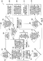
- FIG. 3 shows a flow chart of method 300 of operating the example elevator system 10 of FIG. 1 , in accordance with an embodiment of the disclosure.
- the elevator system 10 is under normal operation.
- the controller 30 is checking whether it has received an evacuation call from a first evacuation floor.
- the controller 30 if the controller 30 has received an evacuation call from a first evacuation floor then the controller 30 moves an elevator car 23 to the first evacuation floor at block 308.
- the controller 30 opens the doors 23a of the elevator car 23 when the elevator car 23 arrives at the first evacuation floor.
- the sensor system 141 monitors the remaining capacity of the elevator car 23.
- the controller 30 will close the elevator doors 23a after a selected period of time has passed or the remaining capacity of the elevator car equals a selected remaining capacity.
- the selected period of time may be enough time to allow passengers to fill the remaining capacity of the elevator car 23, such as, for example ten seconds.
- the selected period of time may change in response to many factors including the remaining capacity and thus there may be a second selected period of time, a third selected period of time, and so on to account for the variations the time required to load passengers at each floor.
- the selected remaining capacity may be a maximum capacity of the elevator car 23 (ex: the maximum capacity is when the remaining capacity is equal to about zero) or the selected remaining capacity may be the remaining capacity of the elevator car 23 after a known number of passengers on the floor have entered the elevator car 23.
- the method 300 will move to block 318 to check whether the remaining capacity is equal to about zero. For example, if the remaining capacity equals about zero then there is no room for any more passengers. At block 318, if the remaining capacity is greater than zero then the controller 30 will check if there are any padding floors at block 324. A padding floor exists if an elevator call has been received from the padding floor indicating that there are still passengers left on the padding floor. At block 318, if the remaining capacity is equal to about zero then the controller 30 moves the elevator car 23 to the discharge floor at block 322.
- the controller 30 moves the elevator car 23 to a padding floor at block 325, opens the doors 23a allowing passengers to enter at block 326 and then closes the doors 23a after a second selected period of time or the remaining capacity equals a selected remaining capacity at block 327. Then the controller checks whether the remaining capacity is equal to about zero at block 329. At block 329, if the remaining capacity equals about zero then the controller 30 moves the elevator car to the discharge floor at block 322 to allow the passengers to evacuate the building 102. At block 329, if there is remaining capacity in the elevator car 23 then the method returns to block 324 to check for more padding floors.
- the controller 30 checks whether an evacuation call has been received from a second evacuation floor at block 330.
- the controller 30 moves the elevator car 23 to the second evacuation floor at block 332, opens the doors 23a allowing passengers to enter at block 334, closes the doors 23a after a third selected period of time or the remaining capacity equals a selected remaining capacity at block 336, and moves the elevator car 23 to the discharge floor at block 332.
- the controller 30 moves the elevator car 23to the discharge floor at block 322.
- the controller 30 will check to see whether the evacuation is still active on the first evacuation floor at block 340. At block 340, if the evacuation is not still active on the first evacuation floor then the method will return to block 304. At block 340, if the evacuation is still active on the first evacuation floor then the method will return to block 308.
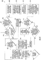
- FIG. 4 shows a flow chart of method 400 of operating the elevator system 10 of FIG. 1 , in accordance with an embodiment of the disclosure.
- the elevator system 10 is under normal operation.
- the controller 30 is checking whether it has received an evacuation call from a first evacuation floor.
- the controller 30 if the controller 30 has received an evacuation call from a first evacuation floor then the controller 30 moves an elevator car 23 to the first evacuation floor at block 408.
- the controller 30 opens the doors 23a of the elevator car 23 when the elevator car 23 arrives at the first evacuation floor.
- the sensor system 141 monitors the remaining capacity of the elevator car 23.
- the controller 30 will close the elevator doors 23a after a selected period of time has passed or the remaining capacity of the elevator car equals a selected remaining capacity.
- the selected period of time may be enough time to allow passengers to fill the remaining capacity of the elevator car 23, such as, for example ten seconds.
- the selected period of time may change in response to many factors including the remaining capacity and thus there may be a second selected period of time, a third selected period of time, and so on to account for the variations the time required to load passengers at each floor.
- the selected remaining capacity may be a maximum capacity of the elevator car 23 (ex: the maximum capacity is when the remaining capacity is equal to about zero) or the selected remaining capacity may be the remaining capacity of the elevator car 23 after a known number of passengers on the floor have entered the elevator car 23.
- the method 400 will move to block 418 to check whether the remaining capacity is equal to about zero. For example, if the remaining capacity equals about zero then there is no room for any more passengers. At block 418, if the remaining capacity is greater than zero then the controller 30 will check if there is a second evacuation floor at block 430. At block 418, if the remaining capacity is equal to about zero then the controller 30 moves the elevator car 23 to the discharge floor at block 422.
- the controller 30 moves the elevator car 23 to the second evacuation floor at block 432, opens the doors 23a allowing passengers to enter at block 434, closes the doors 23a after a second selected period of time or the remaining capacity equals a selected remaining capacity at block 436, and then checks if the remaining capacity is equal to about zero at block 429.
- the controller 30 moves the elevator car to the discharge floor at block 422.
- the controller 30 checks if there are any padding floors at block 424. A padding floor exists if an elevator call has been received from the padding floor indicating that there are still passengers left on the padding floor.
- the controller 30 moves the elevator car 23 to a padding floor at block 425, opens the doors 23a allowing passengers to enter at block 426 and then closes the doors 23a after a second selected period of time or the remaining capacity equals a selected remaining capacity at block 427. Then the controller checks whether the remaining capacity is equal to about zero at block 429. At block 429, if the remaining capacity equals about zero then the controller 30 moves the elevator car to the discharge floor at block 422 to allow the passengers to evacuate the building 102. At block 429, if there is remaining capacity in the elevator car 23 then the method returns to block 424 to check for more padding floors.
- the controller 30 moves the elevator car 23 to the discharge floor at block 422. Once the controller 30 has moved the elevator car 23 to the discharge floor at block 422 and passengers have exited the elevator car 23 at the discharge floor, the controller 30 will check to see whether the evacuation is still active on the first evacuation floor at block 448. At block 440, if the evacuation is not still active on the first evacuation floor then the method will return to block 404. At block 440, if the evacuation is still active on the first evacuation floor then the method will return to block 408.
- embodiments can be in the form of processor-implemented processes and devices for practicing those processes, such as processor.
- Embodiments can also be in the form of computer program code containing instructions embodied in tangible media, such as network cloud storage, SD cards, flash drives, floppy diskettes, CD ROMs, hard drives, or any other computer-readable storage medium, wherein, when the computer program code is loaded into and executed by a computer, the computer becomes a device for practicing the embodiments.
- Embodiments can also be in the form of computer program code, for example, whether stored in a storage medium, loaded into and/or executed by a computer, or transmitted over some transmission medium, loaded into and/or executed by a computer, or transmitted over some transmission medium, such as over electrical wiring or cabling, through fiber optics, or via electromagnetic radiation, wherein, when the computer program code is loaded into an executed by a computer, the computer becomes an device for practicing the embodiments.
- the computer program code segments configure the microprocessor to create specific logic circuits.
Claims (8)
- Procédé de fonctionnement d'un système d'ascenseur (10), le procédé comprenant :la réception d'un appel d'évacuation depuis un premier étage d'évacuation (80d) ;le déplacement d'une cabine d'ascenseur (23) jusqu'au premier étage d'évacuation (80d) ;l'ouverture des portes de la cabine d'ascenseur (23) lorsque la cabine d'ascenseur (23) arrive au premier étage d'évacuation (80d) ;la surveillance, à l'aide d'un système de capteurs (141), d'une capacité restante de la cabine d'ascenseur (23) ; etla fermeture des portes de la cabine d'ascenseur (23) lorsqu'au moins l'une d'une première période de temps sélectionnée s'est écoulée et que la capacité restante est égale à une capacité restante sélectionnée,la réception d'un appel d'ascenseur depuis un étage de remplissage (80b, 80c, 80e, 80f) ; etle déplacement de la cabine d'ascenseur (23) jusqu'à l'étage de remplissage (80b, 80c, 80e, 80f) lorsque la première période de temps sélectionnée s'est écoulée, que la capacité restante est supérieure à zéro et qu'il n'y a pas de second étage d'évacuation, ou que la première période de temps sélectionnée s'est écoulée et que la capacité restante est supérieure à zéro ;dans lequel l'étage de remplissage (80b, 80c, 80e, 80f) se trouve dans un nombre sélectionné d'étages à l'écart du premier étage d'évacuation (80d) ;l'ouverture des portes de la cabine d'ascenseur (23) lorsque la cabine d'ascenseur (23) arrive à l'étage de remplissage (80b, 80c, 80e, 80f) ;la surveillance, à l'aide du système de capteurs (141), de la capacité restante de la cabine d'ascenseur (23) ;la fermeture des portes de la cabine d'ascenseur (23) lorsqu'au moins l'une d'une deuxième période de temps sélectionnée s'est écoulée et que la capacité restante est égale à la capacité restante sélectionnée ;caractérisé en ce qu'il comprend en outre :la réception d'un appel d'évacuation depuis un second étage d'évacuation après que la cabine d'ascenseur (23) est arrivée à l'étage de remplissage (80b, 80c, 80e, 80f) ; etle déplacement de la cabine d'ascenseur (23) jusqu'au second étage d'évacuation lorsque la deuxième période de temps sélectionnée s'est écoulée et que la capacité restante est supérieure à zéro.
- Procédé selon la revendication 1, comprenant en outre :
le déplacement de la cabine d'ascenseur (23) jusqu'à un étage de décharge lorsque la capacité restante est égale à la capacité restante sélectionnée, dans lequel la capacité restante sélectionnée est égale à environ zéro. - Procédé selon la revendication 1 ou 2, comprenant en outre :la réception d'un appel d'évacuation depuis un second étage d'évacuation ; etle déplacement de la cabine d'ascenseur (23) jusqu'au second étage d'évacuation lorsque la première période de temps sélectionnée s'est écoulée et que la capacité restante est supérieure à zéro.
- Procédé selon l'une quelconque des revendications 1 à 3, comprenant en outre :l'ouverture des portes de la cabine d'ascenseur (23) lorsque la cabine d'ascenseur (23) arrive au second étage d'évacuation ;la surveillance, à l'aide d'un système de capteurs (141), de la capacité restante de la cabine d'ascenseur (23) ;la fermeture des portes de la cabine d'ascenseur (23) lorsqu'au moins l'une d'une troisième période de temps sélectionnée s'est écoulée et que la capacité restante est égale à la capacité restante sélectionnée ;la réception d'un appel d'ascenseur depuis un étage de remplissage (80b, 80c, 80e, 80f) ; etle déplacement de la cabine d'ascenseur (23) jusqu'à un étage de remplissage (80b, 80c, 80e, 80f) lorsque la troisième période de temps sélectionnée s'est écoulée et que la capacité restante est supérieure à zéro.
- Procédé selon la revendication 4, comprenant en outre :l'ouverture des portes de la cabine d'ascenseur (23) lorsque la cabine d'ascenseur (23) arrive à l'étage de remplissage (80b, 80c, 80e, 80f) ;la surveillance, à l'aide d'un système de capteurs (141), de la capacité restante de la cabine d'ascenseur (23) ;la fermeture des portes de la cabine d'ascenseur (23) lorsque la capacité restante est égale à la capacité restante sélectionnée ou à environ zéro ; etle déplacement de la cabine d'ascenseur (23) jusqu'à un étage de décharge lorsque la capacité restante est égale à la capacité restante sélectionnée ou à environ zéro.
- Procédé selon l'une quelconque des revendications 1 à 5, comprenant en outre :l'ouverture des portes de la cabine d'ascenseur (23) lorsque la cabine d'ascenseur (23) arrive au second étage d'évacuation ;la surveillance, à l'aide d'un système de capteurs (141), de la capacité restante de la cabine d'ascenseur (23) ;la fermeture des portes de la cabine d'ascenseur (23) lorsque la capacité restante est égale à la capacité restante sélectionnée ou à environ zéro ; etle déplacement de la cabine d'ascenseur (23) jusqu'à un étage de décharge lorsque la capacité restante est égale à la capacité restante sélectionnée ou à environ zéro.
- Dispositif de commande d'un système d'ascenseur (10) comprenant :un processeur ;une mémoire comprenant des instructions exécutables par ordinateur qui, lorsqu'elles sont exécutées par le processeur, amènent le processeur à effectuer des opérations selon le procédé selon l'une quelconque des revendications 1 à 6.
- Produit de programme informatique incorporé de manière tangible dans un support lisible par ordinateur, le produit de programme informatique comportant des instructions qui, lorsqu'elles sont exécutées par un processeur dans un dispositif de commande d'un système d'ascenseur selon la revendication 7, amènent le processeur à effectuer des opérations selon le procédé selon l'une quelconque des revendications 1 à 6.
Applications Claiming Priority (1)
| Application Number | Priority Date | Filing Date | Title |
|---|---|---|---|
| US15/281,163 US10294075B2 (en) | 2016-09-30 | 2016-09-30 | Re-dispatching unoccupied elevator car for occupant evacuation operation |
Publications (2)
| Publication Number | Publication Date |
|---|---|
| EP3301053A1 EP3301053A1 (fr) | 2018-04-04 |
| EP3301053B1 true EP3301053B1 (fr) | 2020-03-25 |
Family
ID=59955418
Family Applications (1)
| Application Number | Title | Priority Date | Filing Date |
|---|---|---|---|
| EP17192560.5A Active EP3301053B1 (fr) | 2016-09-30 | 2017-09-22 | Redistribution de cabine d'ascenseur inoccupé pour une opération d'évacuation des occupants |
Country Status (3)
| Country | Link |
|---|---|
| US (1) | US10294075B2 (fr) |
| EP (1) | EP3301053B1 (fr) |
| CN (1) | CN107879213A (fr) |
Families Citing this family (1)
| Publication number | Priority date | Publication date | Assignee | Title |
|---|---|---|---|---|
| US11370639B2 (en) * | 2017-09-20 | 2022-06-28 | Jessica Williams | Emergency elevator evacuation system |
Family Cites Families (35)
| Publication number | Priority date | Publication date | Assignee | Title |
|---|---|---|---|---|
| US5625176A (en) * | 1995-06-26 | 1997-04-29 | Otis Elevator Company | Crowd service enhancements with multi-deck elevators |
| EP1068142B1 (fr) | 1998-03-31 | 2003-11-19 | ALLEN, Thomas H. | Batiment multi-niveaux equipe d'un systeme d'ascenseur faisant office de sortie de secours et d'evacuation lors d'un incendie |
| US5979607A (en) * | 1998-03-31 | 1999-11-09 | Allen; Thomas H. | Multiple level building with an elevator system operable as a means of emergency egress and evacuation during a fire incident |
| AU4517901A (en) | 1999-12-06 | 2001-06-18 | Science Applications International Corporation | Rapid threat response for minimizing human casualties within a facility |
| JP4628518B2 (ja) | 2000-05-18 | 2011-02-09 | 東芝エレベータ株式会社 | ダブルデッキエレベーター |
| JP2004203623A (ja) | 2002-12-23 | 2004-07-22 | Inventio Ag | 建物の人の緊急避難方法およびシステム、および前記システムを用いた既存の建物の近代化方法 |
| US7366674B2 (en) | 2003-01-24 | 2008-04-29 | Diegane Dione | Occupant management method, system, and program product |
| US7210564B2 (en) | 2003-05-14 | 2007-05-01 | Mitsubishi Denki Dabushiki Kaisha | Fire control system for elevator |
| CN100482559C (zh) | 2003-11-27 | 2009-04-29 | 三菱电机株式会社 | 带多层轿厢电梯的建筑物及其控制系统 |
| JP4675890B2 (ja) | 2004-06-10 | 2011-04-27 | 三菱電機株式会社 | エレベータの火災管制装置 |
| US7621378B2 (en) | 2005-02-14 | 2009-11-24 | Mitsubishi Electric Corporation | System for controlled operation of elevator in case of fire and method of controlled operation of elevator in case of fire |
| CN101014522B (zh) | 2005-09-05 | 2011-09-28 | 三菱电机株式会社 | 组群管理电梯的火灾时避难运转装置 |
| JP5025933B2 (ja) | 2005-09-27 | 2012-09-12 | 三菱電機株式会社 | エレベータ制御装置及びエレベータの運転方法 |
| FI118332B (fi) * | 2005-10-14 | 2007-10-15 | Kone Corp | Hissijärjestelmä |
| JP2007161417A (ja) | 2005-12-14 | 2007-06-28 | Mitsubishi Electric Corp | エレベータ装置 |
| JP5026089B2 (ja) | 2006-01-12 | 2012-09-12 | 三菱電機株式会社 | エレベータの避難時管理装置、及びエレベータの避難時管理方法 |
| US7938232B2 (en) | 2006-01-19 | 2011-05-10 | Mitsubishi Electric Corporation | Evacuation control apparatus for an elevator |
| WO2007096969A1 (fr) | 2006-02-23 | 2007-08-30 | Mitsubishi Denki Kabushiki Kaisha | Dispositif d'aide a l'evacuation pour ascenseur |
| FI118465B (fi) | 2006-03-03 | 2007-11-30 | Kone Corp | Hissijärjestelmä |
| JP4932855B2 (ja) | 2007-01-25 | 2012-05-16 | 三菱電機株式会社 | エレベータ制御システム |
| US7688212B2 (en) | 2007-07-26 | 2010-03-30 | Simplexgrinnell Lp | Method and apparatus for providing occupancy information in a fire alarm system |
| CN101868798B (zh) | 2007-09-20 | 2013-08-14 | 联合工艺公司 | 基于模型的流出支持系统 |
| KR101203357B1 (ko) | 2007-10-10 | 2012-11-20 | 미쓰비시덴키 가부시키가이샤 | 엘리베이터의 피난 지원 장치 |
| FI119686B (fi) * | 2007-10-11 | 2009-02-13 | Kone Corp | Hissijärjestelmä |
| WO2009054065A1 (fr) | 2007-10-26 | 2009-04-30 | Mitsubishi Electric Corporation | Système de support de refuge pour ascenseur à cabines superposées |
| JP5033723B2 (ja) * | 2008-06-30 | 2012-09-26 | 株式会社日立製作所 | エレベーターの運転制御システム |
| WO2010082650A1 (fr) * | 2009-01-19 | 2010-07-22 | 三菱電機株式会社 | Système d'ascenseur |
| JP5550302B2 (ja) | 2009-10-19 | 2014-07-16 | 東芝エレベータ株式会社 | エレベータの救出運転システム |
| FI122222B (fi) * | 2009-12-22 | 2011-10-14 | Kone Corp | Hissijärjestelmä |
| FI125122B (fi) | 2010-02-01 | 2015-06-15 | Kone Corp | Hissijärjestelmä |
| JP5500253B2 (ja) | 2010-06-29 | 2014-05-21 | 三菱電機株式会社 | エレベーターの制御装置 |
| JP5615104B2 (ja) * | 2010-09-08 | 2014-10-29 | 東芝エレベータ株式会社 | エレベータの制御装置 |
| JP5744201B2 (ja) * | 2011-06-30 | 2015-07-08 | 三菱電機株式会社 | エレベータ装置 |
| EP3003945A4 (fr) | 2013-05-31 | 2017-03-15 | KONE Corporation | Système d'évacuation par ascenseur |
| CN107000984B (zh) * | 2014-11-21 | 2019-04-09 | 三菱电机株式会社 | 电梯装置 |
-
2016
- 2016-09-30 US US15/281,163 patent/US10294075B2/en active Active
-
2017
- 2017-09-22 EP EP17192560.5A patent/EP3301053B1/fr active Active
- 2017-09-29 CN CN201710913718.3A patent/CN107879213A/zh active Pending
Non-Patent Citations (1)
| Title |
|---|
| None * |
Also Published As
| Publication number | Publication date |
|---|---|
| US10294075B2 (en) | 2019-05-21 |
| US20180093856A1 (en) | 2018-04-05 |
| CN107879213A (zh) | 2018-04-06 |
| EP3301053A1 (fr) | 2018-04-04 |
Similar Documents
| Publication | Publication Date | Title |
|---|---|---|
| EP3301056B1 (fr) | Fourniture d'informations d'état d'ascenseur améliorée pour des systèmes d'alarme incendie | |
| EP3301055A2 (fr) | Opération d'évacuation des occupants par attribution d'un nombre variable de voitures aux étages dans une zone d'évacuation | |
| EP3301052B1 (fr) | Coordination de groupe d'ascenseurs à l'intérieur d'un bâtiment pour l'évacuation des occupants | |
| EP3281904B1 (fr) | Systèmes et procédés de commande pour ascenseurs | |
| EP3299324B1 (fr) | Écrans d'affichage dynamiques d'ascenseur pour messagerie et communication | |
| AU2014262180B2 (en) | Method for condition monitoring of elevator ropes and arrangement for the same | |
| US20190077633A1 (en) | Elevator device | |
| CN105980284A (zh) | 电梯中的制动器操作管理 | |
| JP5419936B2 (ja) | 災害対応型エレベータシステム | |
| EP3872018B1 (fr) | Système de surveillance d'ascenseur | |
| CN104229571B (zh) | 电梯 | |
| EP3309103A1 (fr) | Procédé d'opération d'évacuation des occupants au moyendes ascenseurs à compartiments multiples | |
| EP3492416B1 (fr) | Gestion d'un groupe d'ascenseurs pour l'évacuation des occupants | |
| CN111108053B (zh) | 安全的电梯井道和轿厢顶部访问 | |
| EP3301053B1 (fr) | Redistribution de cabine d'ascenseur inoccupé pour une opération d'évacuation des occupants | |
| EP3305706A1 (fr) | Affichage d'opération d'évacuation d'occupants | |
| EP3301054B1 (fr) | Opération d'évacuation des occupants optimisée par l'utilisation de la capacité restante pour des ascenseurs à compartiments multiples | |
| JP6749860B2 (ja) | エレべーター制御システム | |
| WO2019106778A1 (fr) | Dispositif de commande d'ascenseur, ascenseur et procédé de commande d'ascenseur | |
| WO2023231040A1 (fr) | Procédé et ascenseur permettant de déterminer un dysfonctionnement de système de détection d'emprisonnement dans un ascenseur | |
| JP6786895B2 (ja) | エレベーターの接触抑制システム | |
| JP2009029575A (ja) | エレベータ制御装置 |
Legal Events
| Date | Code | Title | Description |
|---|---|---|---|
| PUAI | Public reference made under article 153(3) epc to a published international application that has entered the european phase |
Free format text: ORIGINAL CODE: 0009012 |
|
| STAA | Information on the status of an ep patent application or granted ep patent |
Free format text: STATUS: THE APPLICATION HAS BEEN PUBLISHED |
|
| AK | Designated contracting states |
Kind code of ref document: A1 Designated state(s): AL AT BE BG CH CY CZ DE DK EE ES FI FR GB GR HR HU IE IS IT LI LT LU LV MC MK MT NL NO PL PT RO RS SE SI SK SM TR |
|
| AX | Request for extension of the european patent |
Extension state: BA ME |
|
| STAA | Information on the status of an ep patent application or granted ep patent |
Free format text: STATUS: REQUEST FOR EXAMINATION WAS MADE |
|
| 17P | Request for examination filed |
Effective date: 20181002 |
|
| RBV | Designated contracting states (corrected) |
Designated state(s): AL AT BE BG CH CY CZ DE DK EE ES FI FR GB GR HR HU IE IS IT LI LT LU LV MC MK MT NL NO PL PT RO RS SE SI SK SM TR |
|
| GRAP | Despatch of communication of intention to grant a patent |
Free format text: ORIGINAL CODE: EPIDOSNIGR1 |
|
| STAA | Information on the status of an ep patent application or granted ep patent |
Free format text: STATUS: GRANT OF PATENT IS INTENDED |
|
| INTG | Intention to grant announced |
Effective date: 20191203 |
|
| GRAS | Grant fee paid |
Free format text: ORIGINAL CODE: EPIDOSNIGR3 |
|
| GRAA | (expected) grant |
Free format text: ORIGINAL CODE: 0009210 |
|
| STAA | Information on the status of an ep patent application or granted ep patent |
Free format text: STATUS: THE PATENT HAS BEEN GRANTED |
|
| AK | Designated contracting states |
Kind code of ref document: B1 Designated state(s): AL AT BE BG CH CY CZ DE DK EE ES FI FR GB GR HR HU IE IS IT LI LT LU LV MC MK MT NL NO PL PT RO RS SE SI SK SM TR |
|
| REG | Reference to a national code |
Ref country code: GB Ref legal event code: FG4D |
|
| REG | Reference to a national code |
Ref country code: AT Ref legal event code: REF Ref document number: 1248334 Country of ref document: AT Kind code of ref document: T Effective date: 20200415 Ref country code: IE Ref legal event code: FG4D |
|
| REG | Reference to a national code |
Ref country code: DE Ref legal event code: R096 Ref document number: 602017013525 Country of ref document: DE |
|
| PG25 | Lapsed in a contracting state [announced via postgrant information from national office to epo] |
Ref country code: NO Free format text: LAPSE BECAUSE OF FAILURE TO SUBMIT A TRANSLATION OF THE DESCRIPTION OR TO PAY THE FEE WITHIN THE PRESCRIBED TIME-LIMIT Effective date: 20200625 Ref country code: FI Free format text: LAPSE BECAUSE OF FAILURE TO SUBMIT A TRANSLATION OF THE DESCRIPTION OR TO PAY THE FEE WITHIN THE PRESCRIBED TIME-LIMIT Effective date: 20200325 Ref country code: RS Free format text: LAPSE BECAUSE OF FAILURE TO SUBMIT A TRANSLATION OF THE DESCRIPTION OR TO PAY THE FEE WITHIN THE PRESCRIBED TIME-LIMIT Effective date: 20200325 |
|
| PG25 | Lapsed in a contracting state [announced via postgrant information from national office to epo] |
Ref country code: BG Free format text: LAPSE BECAUSE OF FAILURE TO SUBMIT A TRANSLATION OF THE DESCRIPTION OR TO PAY THE FEE WITHIN THE PRESCRIBED TIME-LIMIT Effective date: 20200625 Ref country code: GR Free format text: LAPSE BECAUSE OF FAILURE TO SUBMIT A TRANSLATION OF THE DESCRIPTION OR TO PAY THE FEE WITHIN THE PRESCRIBED TIME-LIMIT Effective date: 20200626 Ref country code: LV Free format text: LAPSE BECAUSE OF FAILURE TO SUBMIT A TRANSLATION OF THE DESCRIPTION OR TO PAY THE FEE WITHIN THE PRESCRIBED TIME-LIMIT Effective date: 20200325 Ref country code: SE Free format text: LAPSE BECAUSE OF FAILURE TO SUBMIT A TRANSLATION OF THE DESCRIPTION OR TO PAY THE FEE WITHIN THE PRESCRIBED TIME-LIMIT Effective date: 20200325 Ref country code: HR Free format text: LAPSE BECAUSE OF FAILURE TO SUBMIT A TRANSLATION OF THE DESCRIPTION OR TO PAY THE FEE WITHIN THE PRESCRIBED TIME-LIMIT Effective date: 20200325 |
|
| REG | Reference to a national code |
Ref country code: NL Ref legal event code: MP Effective date: 20200325 |
|
| REG | Reference to a national code |
Ref country code: LT Ref legal event code: MG4D |
|
| PG25 | Lapsed in a contracting state [announced via postgrant information from national office to epo] |
Ref country code: NL Free format text: LAPSE BECAUSE OF FAILURE TO SUBMIT A TRANSLATION OF THE DESCRIPTION OR TO PAY THE FEE WITHIN THE PRESCRIBED TIME-LIMIT Effective date: 20200325 |
|
| PG25 | Lapsed in a contracting state [announced via postgrant information from national office to epo] |
Ref country code: PT Free format text: LAPSE BECAUSE OF FAILURE TO SUBMIT A TRANSLATION OF THE DESCRIPTION OR TO PAY THE FEE WITHIN THE PRESCRIBED TIME-LIMIT Effective date: 20200818 Ref country code: LT Free format text: LAPSE BECAUSE OF FAILURE TO SUBMIT A TRANSLATION OF THE DESCRIPTION OR TO PAY THE FEE WITHIN THE PRESCRIBED TIME-LIMIT Effective date: 20200325 Ref country code: SK Free format text: LAPSE BECAUSE OF FAILURE TO SUBMIT A TRANSLATION OF THE DESCRIPTION OR TO PAY THE FEE WITHIN THE PRESCRIBED TIME-LIMIT Effective date: 20200325 Ref country code: IS Free format text: LAPSE BECAUSE OF FAILURE TO SUBMIT A TRANSLATION OF THE DESCRIPTION OR TO PAY THE FEE WITHIN THE PRESCRIBED TIME-LIMIT Effective date: 20200725 Ref country code: RO Free format text: LAPSE BECAUSE OF FAILURE TO SUBMIT A TRANSLATION OF THE DESCRIPTION OR TO PAY THE FEE WITHIN THE PRESCRIBED TIME-LIMIT Effective date: 20200325 Ref country code: CZ Free format text: LAPSE BECAUSE OF FAILURE TO SUBMIT A TRANSLATION OF THE DESCRIPTION OR TO PAY THE FEE WITHIN THE PRESCRIBED TIME-LIMIT Effective date: 20200325 Ref country code: SM Free format text: LAPSE BECAUSE OF FAILURE TO SUBMIT A TRANSLATION OF THE DESCRIPTION OR TO PAY THE FEE WITHIN THE PRESCRIBED TIME-LIMIT Effective date: 20200325 Ref country code: EE Free format text: LAPSE BECAUSE OF FAILURE TO SUBMIT A TRANSLATION OF THE DESCRIPTION OR TO PAY THE FEE WITHIN THE PRESCRIBED TIME-LIMIT Effective date: 20200325 |
|
| REG | Reference to a national code |
Ref country code: AT Ref legal event code: MK05 Ref document number: 1248334 Country of ref document: AT Kind code of ref document: T Effective date: 20200325 |
|
| REG | Reference to a national code |
Ref country code: DE Ref legal event code: R097 Ref document number: 602017013525 Country of ref document: DE |
|
| PG25 | Lapsed in a contracting state [announced via postgrant information from national office to epo] |
Ref country code: IT Free format text: LAPSE BECAUSE OF FAILURE TO SUBMIT A TRANSLATION OF THE DESCRIPTION OR TO PAY THE FEE WITHIN THE PRESCRIBED TIME-LIMIT Effective date: 20200325 Ref country code: DK Free format text: LAPSE BECAUSE OF FAILURE TO SUBMIT A TRANSLATION OF THE DESCRIPTION OR TO PAY THE FEE WITHIN THE PRESCRIBED TIME-LIMIT Effective date: 20200325 Ref country code: ES Free format text: LAPSE BECAUSE OF FAILURE TO SUBMIT A TRANSLATION OF THE DESCRIPTION OR TO PAY THE FEE WITHIN THE PRESCRIBED TIME-LIMIT Effective date: 20200325 Ref country code: AT Free format text: LAPSE BECAUSE OF FAILURE TO SUBMIT A TRANSLATION OF THE DESCRIPTION OR TO PAY THE FEE WITHIN THE PRESCRIBED TIME-LIMIT Effective date: 20200325 |
|
| PLBE | No opposition filed within time limit |
Free format text: ORIGINAL CODE: 0009261 |
|
| STAA | Information on the status of an ep patent application or granted ep patent |
Free format text: STATUS: NO OPPOSITION FILED WITHIN TIME LIMIT |
|
| PG25 | Lapsed in a contracting state [announced via postgrant information from national office to epo] |
Ref country code: PL Free format text: LAPSE BECAUSE OF FAILURE TO SUBMIT A TRANSLATION OF THE DESCRIPTION OR TO PAY THE FEE WITHIN THE PRESCRIBED TIME-LIMIT Effective date: 20200325 |
|
| 26N | No opposition filed |
Effective date: 20210112 |
|
| REG | Reference to a national code |
Ref country code: CH Ref legal event code: PL |
|
| PG25 | Lapsed in a contracting state [announced via postgrant information from national office to epo] |
Ref country code: SI Free format text: LAPSE BECAUSE OF FAILURE TO SUBMIT A TRANSLATION OF THE DESCRIPTION OR TO PAY THE FEE WITHIN THE PRESCRIBED TIME-LIMIT Effective date: 20200325 |
|
| REG | Reference to a national code |
Ref country code: BE Ref legal event code: MM Effective date: 20200930 |
|
| PG25 | Lapsed in a contracting state [announced via postgrant information from national office to epo] |
Ref country code: LU Free format text: LAPSE BECAUSE OF NON-PAYMENT OF DUE FEES Effective date: 20200922 |
|
| PG25 | Lapsed in a contracting state [announced via postgrant information from national office to epo] |
Ref country code: BE Free format text: LAPSE BECAUSE OF NON-PAYMENT OF DUE FEES Effective date: 20200930 Ref country code: CH Free format text: LAPSE BECAUSE OF NON-PAYMENT OF DUE FEES Effective date: 20200930 Ref country code: LI Free format text: LAPSE BECAUSE OF NON-PAYMENT OF DUE FEES Effective date: 20200930 Ref country code: IE Free format text: LAPSE BECAUSE OF NON-PAYMENT OF DUE FEES Effective date: 20200922 |
|
| GBPC | Gb: european patent ceased through non-payment of renewal fee |
Effective date: 20210922 |
|
| PG25 | Lapsed in a contracting state [announced via postgrant information from national office to epo] |
Ref country code: TR Free format text: LAPSE BECAUSE OF FAILURE TO SUBMIT A TRANSLATION OF THE DESCRIPTION OR TO PAY THE FEE WITHIN THE PRESCRIBED TIME-LIMIT Effective date: 20200325 Ref country code: MT Free format text: LAPSE BECAUSE OF FAILURE TO SUBMIT A TRANSLATION OF THE DESCRIPTION OR TO PAY THE FEE WITHIN THE PRESCRIBED TIME-LIMIT Effective date: 20200325 Ref country code: CY Free format text: LAPSE BECAUSE OF FAILURE TO SUBMIT A TRANSLATION OF THE DESCRIPTION OR TO PAY THE FEE WITHIN THE PRESCRIBED TIME-LIMIT Effective date: 20200325 |
|
| PG25 | Lapsed in a contracting state [announced via postgrant information from national office to epo] |
Ref country code: MK Free format text: LAPSE BECAUSE OF FAILURE TO SUBMIT A TRANSLATION OF THE DESCRIPTION OR TO PAY THE FEE WITHIN THE PRESCRIBED TIME-LIMIT Effective date: 20200325 Ref country code: MC Free format text: LAPSE BECAUSE OF FAILURE TO SUBMIT A TRANSLATION OF THE DESCRIPTION OR TO PAY THE FEE WITHIN THE PRESCRIBED TIME-LIMIT Effective date: 20200325 Ref country code: AL Free format text: LAPSE BECAUSE OF FAILURE TO SUBMIT A TRANSLATION OF THE DESCRIPTION OR TO PAY THE FEE WITHIN THE PRESCRIBED TIME-LIMIT Effective date: 20200325 |
|
| PG25 | Lapsed in a contracting state [announced via postgrant information from national office to epo] |
Ref country code: GB Free format text: LAPSE BECAUSE OF NON-PAYMENT OF DUE FEES Effective date: 20210922 |
|
| PGFP | Annual fee paid to national office [announced via postgrant information from national office to epo] |
Ref country code: FR Payment date: 20230822 Year of fee payment: 7 Ref country code: DE Payment date: 20230822 Year of fee payment: 7 |