EP3300831B1 - Procédé de coupage en utilisant une buse laser avec élément mobile à profil externe amélioré - Google Patents
Procédé de coupage en utilisant une buse laser avec élément mobile à profil externe amélioré Download PDFInfo
- Publication number
- EP3300831B1 EP3300831B1 EP17197254.0A EP17197254A EP3300831B1 EP 3300831 B1 EP3300831 B1 EP 3300831B1 EP 17197254 A EP17197254 A EP 17197254A EP 3300831 B1 EP3300831 B1 EP 3300831B1
- Authority
- EP
- European Patent Office
- Prior art keywords
- skirt
- movable element
- nozzle
- gas
- cutting
- Prior art date
- Legal status (The legal status is an assumption and is not a legal conclusion. Google has not performed a legal analysis and makes no representation as to the accuracy of the status listed.)
- Active
Links
Images


Classifications
-
- B—PERFORMING OPERATIONS; TRANSPORTING
- B23—MACHINE TOOLS; METAL-WORKING NOT OTHERWISE PROVIDED FOR
- B23K—SOLDERING OR UNSOLDERING; WELDING; CLADDING OR PLATING BY SOLDERING OR WELDING; CUTTING BY APPLYING HEAT LOCALLY, e.g. FLAME CUTTING; WORKING BY LASER BEAM
- B23K26/00—Working by laser beam, e.g. welding, cutting or boring
- B23K26/08—Devices involving relative movement between laser beam and workpiece
- B23K26/0869—Devices involving movement of the laser head in at least one axial direction
- B23K26/0876—Devices involving movement of the laser head in at least one axial direction in at least two axial directions
-
- B—PERFORMING OPERATIONS; TRANSPORTING
- B23—MACHINE TOOLS; METAL-WORKING NOT OTHERWISE PROVIDED FOR
- B23K—SOLDERING OR UNSOLDERING; WELDING; CLADDING OR PLATING BY SOLDERING OR WELDING; CUTTING BY APPLYING HEAT LOCALLY, e.g. FLAME CUTTING; WORKING BY LASER BEAM
- B23K26/00—Working by laser beam, e.g. welding, cutting or boring
- B23K26/14—Working by laser beam, e.g. welding, cutting or boring using a fluid stream, e.g. a jet of gas, in conjunction with the laser beam; Nozzles therefor
- B23K26/1462—Nozzles; Features related to nozzles
- B23K26/1464—Supply to, or discharge from, nozzles of media, e.g. gas, powder, wire
- B23K26/1476—Features inside the nozzle for feeding the fluid stream through the nozzle
-
- B—PERFORMING OPERATIONS; TRANSPORTING
- B23—MACHINE TOOLS; METAL-WORKING NOT OTHERWISE PROVIDED FOR
- B23K—SOLDERING OR UNSOLDERING; WELDING; CLADDING OR PLATING BY SOLDERING OR WELDING; CUTTING BY APPLYING HEAT LOCALLY, e.g. FLAME CUTTING; WORKING BY LASER BEAM
- B23K26/00—Working by laser beam, e.g. welding, cutting or boring
- B23K26/14—Working by laser beam, e.g. welding, cutting or boring using a fluid stream, e.g. a jet of gas, in conjunction with the laser beam; Nozzles therefor
- B23K26/1462—Nozzles; Features related to nozzles
- B23K26/1488—Means for protecting nozzles, e.g. the tip surface
-
- B—PERFORMING OPERATIONS; TRANSPORTING
- B23—MACHINE TOOLS; METAL-WORKING NOT OTHERWISE PROVIDED FOR
- B23K—SOLDERING OR UNSOLDERING; WELDING; CLADDING OR PLATING BY SOLDERING OR WELDING; CUTTING BY APPLYING HEAT LOCALLY, e.g. FLAME CUTTING; WORKING BY LASER BEAM
- B23K26/00—Working by laser beam, e.g. welding, cutting or boring
- B23K26/36—Removing material
- B23K26/38—Removing material by boring or cutting
-
- B—PERFORMING OPERATIONS; TRANSPORTING
- B23—MACHINE TOOLS; METAL-WORKING NOT OTHERWISE PROVIDED FOR
- B23K—SOLDERING OR UNSOLDERING; WELDING; CLADDING OR PLATING BY SOLDERING OR WELDING; CUTTING BY APPLYING HEAT LOCALLY, e.g. FLAME CUTTING; WORKING BY LASER BEAM
- B23K2103/00—Materials to be soldered, welded or cut
- B23K2103/02—Iron or ferrous alloys
- B23K2103/04—Steel or steel alloys
- B23K2103/05—Stainless steel
Definitions
- the invention relates to a method for cutting a workpiece by laser beam using a nozzle with an internal movable element comprising a skirt making it possible to concentrate the cutting gas in the cutting kerf and further offering improved industrial implementation and service life.
- Laser beam cutting requires the use of a nozzle, generally made of copper, which channels the gas and allows the laser beam to pass through.
- Nozzles typically have outlet orifice diameters between 0.5 and 3 mm for a working distance between 0.6 and 2 mm.
- the passage section of a nozzle with an exit orifice of diameter equal to 1.5 mm is 25 times greater than the section of the focal spot created by the laser beam passing through this nozzle.
- JP63040695 A discloses a laser cutting nozzle that aims to solve the problem of reducing scratches in the sheet metal being cut.
- the document US-A-4,031,351 discloses a laser cutting nozzle comprising a movable element whose end is pressed by a spring against the surface of the part to be cut to promote the injection of cutting gas into the kerf.
- this nozzle comprises an elastic element exerting an elastic restoring force on the movable element in a direction tending to move it away from the sheet metal.
- JP-A-7251287 does not allow the moving element to be moved away from the sheet metal and we are faced with the problems mentioned above, the moving element permanently protruding outside the nozzle body. This also poses a problem during drilling phases, as excessive proximity of the nozzle to the sheet metal should be avoided due to the significant projections of molten metal generated.
- the problem which arises is therefore to propose a laser beam cutting nozzle for which the aforementioned problems are greatly reduced, or even eliminated, in particular a laser nozzle whose movement on the cut sheet is significantly less disturbed in the event of obstacles on the surface of said sheet and for which the shocks resulting from the encounter of the nozzle with said obstacles are greatly reduced compared to existing solutions.
- the laser nozzle of the present invention must be able to be implemented industrially, have improved robustness and lifespan compared to existing solutions, and not disrupt the operation of the cutting machine on which said nozzle is installed.
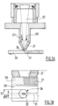
- FIG. 1A represents the focusing head 20 of a conventional laser cutting installation, to which is fixed a conventional laser nozzle 21 which is crossed by a focused laser beam and by assistance gas (arrow 23) used to expel the metal molten by the beam from the cutting groove 31 formed by the beam 22 in the metal part to be cut 30, for example a steel or stainless steel sheet.
- the assist gas may be an active gas, such as oxygen, air, CO2 , hydrogen, or an inert gas, such as argon, nitrogen, helium, or a mixture of several of these active and/or inert gases.
- active gas such as oxygen, air, CO2 , hydrogen
- inert gas such as argon, nitrogen, helium, or a mixture of several of these active and/or inert gases.
- the composition of the gas is chosen in particular according to the nature of the part to be cut.
- the beam which impacts the part will melt the metal which will be expelled below the part by the pressure of the assist gas.
- FIG. 1B allows the section S1 of passage of the orifice 24 of the nozzle 21 to be clearly visualized in relation to the size S2 of the focal spot of the beam 22.
- the section S1 is much greater than the size S2 of the focal spot of the beam 22, which results, with conventional nozzles, in a high consumption of assistance gas, of which only a small proportion will be used to expel the molten metal from the cutting groove 31.
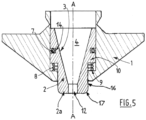
- the laser nozzle comprises at least two essential components, namely a nozzle body 1 cooperating with a movable element 2 arranged and movable inside the nozzle body 1, one embodiment of which is illustrated in Figures 2 and 3 .
- the nozzle body 1 which is formed from a conductive material, for example copper or brass, is intended to be fixed to the laser focusing head 20 of the laser installation.
- the nozzle body 1 is a part of revolution and is crossed from one side to the other by an axial housing 5 of axis AA which extends from the rear face 1b of the body 1 to the front face 1a of said body 1.
- the axial housing 5 opens at the level of the two front faces 1a and rear faces 1b of the nozzle body 1.
- the rear face 1b therefore carries a first inlet orifice 11', while the front face 1a carries a first outlet orifice 11 of the nozzle body 1, the first inlet orifices 11' and outlet orifices 11 being coaxial with axis AA.
- This axial housing 5 is in fact a recess, for example of cylindrical shape comprising an internal shoulder 9 projecting radially towards the center of the housing 5, said internal shoulder 9 being formed by a restriction 15 of the section of the axial housing 5 at the level of the first outlet orifice 11 located on the front face 1a of the nozzle body 1.
- the nozzle the document FR n°1154224 further comprises a movable element 2 which is inserted into the housing 5 of the nozzle body 1, preferably coaxially with the body 1, as visible in Figure 3
- This mobile element 2 is capable of and designed to move in translation along the axis AA inside the housing 5 of the nozzle body 1.
- this mobile element 2 comprises a front part 2a forming a skirt 6 of cylindrical shape, that is to say tubular, arranged in the axial housing 5 of the nozzle body 1 and comprising an axial passage 4 with a second outlet orifice 12 opening at the level of the front part 2 forming said skirt 6.
- the laser beam 22 and the assist gas 23 pass through the axial passage 4 of the movable element 2 and exit through the second outlet orifice 12 opening at the level of the front part 2a forming said skirt 6.
- the movable element 2 is axially movable relative to the body 1 of the nozzle along the axis AA. In fact, the movable element 2 moves under the effect of the pressure of the assist gas 23 which is exerted on said movable element 2, which tends to push it towards the part to be cut 30.
- the gas will be channeled by the skirt 6 and will be concentrated at the level of the laser task and therefore of the bleeding, which will greatly improve its efficiency and the expulsion of the metal will be better.
- An elastic element 8 such as a spring, is arranged in the axial housing 5, between the nozzle body 1 and the movable element 2 so as to exert an elastic return force on the movable element 2 in a direction tending to move it away from the part to be cut.
- the elastic element 8 thus makes it possible to limit the phenomenon of wear of the skirt 6 during the phases of piercing the sheet metal which generally precede the cutting phases. Indeed, the piercing is most often carried out with low gas pressures, typically less than 4 bar. The elastic element then exerts a sufficient restoring force so that the skirt 6 rises completely or almost completely in the housing 5 and is thus protected from projections of molten metal generated by the piercing.
- the elastic element 8 facilitates rapid movements of the cutting head at a short distance above the sheet metal, without cutting gas or beam, since the gas pressure then ceases to be exerted on the moving element and the skirt 6 returns inside the housing 5. Only the skirt 6 rises and it is not necessary to raise the focusing head supporting the nozzle.
- the mobile element 2 comprises a front part 2a forming a skirt 6 of cylindrical shape, that is to say of constant external diameter along the axis AA.
- this cylindrical shape poses a problem when obstacles, irregularities or excess thicknesses, or unevennesses, higher than the level of the upper surface of the sheet to be cut, are present on the surface of the sheet to be cut, for example as a result of projections of molten metal or cut pieces remaining stuck in the skeleton of the sheet.
- the external peripheral wall of the front part 2a constitutes a wall perpendicular to the surface of the sheet to be cut, i.e. vertical, whose resistance to an obstacle is relatively high, in particular at the high cutting speeds encountered in laser cutting, typically between 0.1 and 50 m/min, depending on the thickness of the sheet to be cut.
- the cylindrical external profile of the skirt promotes frontal impacts between the external surface of said skirt and any obstacles possibly present on the sheet.
- the present invention proposes a laser nozzle with an improved moving element, in particular the front part 2a of which forms a skirt and is capable of and designed to move over obstacles, irregularities or unevenness, when the moving element is in its working position, i.e. in contact with the upper surface of the sheet metal to be cut.
- the front part 2a of said mobile element comprises an end portion shaped to pass over a slope or an obstacle without or with a greatly reduced impact at the level of the skirt 6, and without or very little reduction in the speed of movement of the nozzle.
- end portion is meant a portion of the front part 2a located at the end of said front part, that is to say opposite the upper surface of the sheet to be cut.
- the end portion 17 comprises at least one chamfer 18 forming an angle ⁇ relative to the front face 1a of the nozzle body 1.
- the angle ⁇ of the at least one chamfer 18 is between 0.1 and 80°, preferably between 10 and 45°.
- the end portion 17 comprises a single chamfer 18.
- the external profile of the end portion 17 is of truncated cone shape.
- the front part 2a further comprises a cylindrical portion 16 of substantially constant external diameter, preferably arranged upstream of the end portion 17, that is to say further from the second outlet orifice 12 than the end portion 17.
- the external profile of the end portion 17 comprises at least one portion of curvilinear shape.
- the external profile of the end portion 17 comprises at least one portion of convex shape.
- the radius of curvature of the at least one portion of convex shape is typically between 0.1 and 2 mm.
- This nozzle thus makes it possible to eliminate or greatly limit the presence of sharp edges at the end of the front part 2a.
- the cylindrical portion 16 has an external diameter preferably between 3 and 8 mm, more preferably of the order of 6 mm.
- the end portion 17 has an external diameter of between 2.5 and 7 mm, preferably of the order of 4 mm.
- the external peripheral wall of the movable element 2 comprises a stop 10, preferably an annular stop extending over all or part of the periphery of said movable element 2, the elastic element 8 being positioned between the shoulder 9 and the stop 10.
- the nozzle of the invention has the other advantage of being compatible with capacitive sensor systems.
- the part made of copper or other conductive material adapts to the height specified by the capacitive sensor, like a standard nozzle. It is the movable insert 2 which, under the pressure of the gas, comes into contact with the sheet 30 to be cut and thus limits gas leaks.
- the mobile element 2 is preferably formed from an electrically insulating material, composite, technical ceramic, polymer, for example polyetheretherketone (Peek), Vespel ® , ceramic or pyrex, and takes up the internal geometry of a laser cutting nozzle, that is to say that it can have a conical internal profile, with a cylindrical or non-cylindrical outlet channel, truncated cone-shaped, of convergent/divergent type (i.e. Laval nozzle) or any other suitable geometry.
- an electrically insulating material composite, technical ceramic, polymer, for example polyetheretherketone (Peek), Vespel ® , ceramic or pyrex
- takes up the internal geometry of a laser cutting nozzle that is to say that it can have a conical internal profile, with a cylindrical or non-cylindrical outlet channel, truncated cone-shaped, of convergent/divergent type (i.e. Laval nozzle) or any other suitable geometry.
- electrically insulating material we mean a material which does not conduct electricity, that is to say which prevents the passage of electric current between two electrically conductive elements.
- the movable element 2 is a part of revolution formed from a single block of material.
- the mobile element 2 is not formed from an electrically insulating material
- at least a portion of the external surface of the mobile element 2 is covered with a layer of electrically insulating material, whether or not integral with the mobile element 2.
- This layer of insulating material then serves as an electrically insulating interface between the mobile element 2 and the nozzle body 1.
- the nozzle of the invention comprises a movable element 2 whose outlet orifice diameter 12 is between 0.5 and 5 mm.
- the movable element 2 can occupy intermediate positions in which the skirt 6 only partially projects outside the axial housing 5 of the nozzle body 1. These intermediate positions can be in particular a function of the pressure exerted by the gas on the movable element 2.
- the shape of the extreme portion allows the skirt 6 to pass over a slope or a specific obstacle by promoting the rise of the skirt towards the housing 5 and avoids frontal impacts with obstacles on the sheet metal.
- the elastic element 8 makes it possible to limit the pressure exerted by the movable element 2 on the part to be cut when the latter moves towards the part under the effect of the cutting gas. More precisely, the restoring force of the elastic element 8 is advantageously dimensioned so as to keep the movable element 2 in contact with the part to be cut while limiting the pressure that said element exerts on the sheet, to greatly minimize, or even eliminate, any risk of deformation of the sheet from which the part is cut, of scratches on the surface of the sheet, and of entrainment of the sheet.
- the present invention provides greater flexibility of movement to the skirt 6 and allows it to follow the variations in levels which may occur on the surface of the sheet metal to be cut, which improves its industrial implementation.
- the solution of the present invention thus leads to a nozzle with a moving element with improved robustness, service life and implementation compared to a nozzle according to the document FR n°1154224 .
- the laser focusing head is equipped, depending on the case, with a standard nozzle with an outlet orifice of 1.8 mm diameter or with a nozzle according to the Figure 3 with cylindrical movable skirt and axial passage of conical profile with cylindrical outlet channel of 1.8 mm diameter.
- the external profile of the movable skirt includes a chamfer of an angle ⁇ of approximately 30° relative to the horizontal, i.e. relative to the front face of the nozzle body.
- the assist gas used is nitrogen.
- the sheet to be cut is made of 5 mm thick 304 L stainless steel.
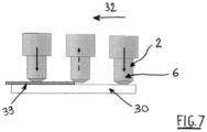
- a drop of 0.8 mm height is simulated on an area of the sheet to be cut by covering a portion of the sheet to be cut with another piece of sheet 0.8 mm thick, as shown diagrammatically in the Figure 7 .
- the laser beam has a power of 4 kW and the cutting speed is 2.6 m/min
Landscapes
- Physics & Mathematics (AREA)
- Optics & Photonics (AREA)
- Engineering & Computer Science (AREA)
- Plasma & Fusion (AREA)
- Mechanical Engineering (AREA)
- Laser Beam Processing (AREA)
Applications Claiming Priority (3)
| Application Number | Priority Date | Filing Date | Title |
|---|---|---|---|
| FR1253089A FR2989013B1 (fr) | 2012-04-04 | 2012-04-04 | Buse laser avec element mobile a profil externe ameliore |
| PCT/FR2013/050291 WO2013150195A1 (fr) | 2012-04-04 | 2013-02-13 | Buse laser avec élément mobile à profil externe amélioré |
| EP13708204.6A EP2834035B1 (fr) | 2012-04-04 | 2013-02-13 | Buse laser avec élément mobile à profil externe amélioré |
Related Parent Applications (2)
| Application Number | Title | Priority Date | Filing Date |
|---|---|---|---|
| EP13708204.6A Division EP2834035B1 (fr) | 2012-04-04 | 2013-02-13 | Buse laser avec élément mobile à profil externe amélioré |
| EP13708204.6A Division-Into EP2834035B1 (fr) | 2012-04-04 | 2013-02-13 | Buse laser avec élément mobile à profil externe amélioré |
Publications (2)
| Publication Number | Publication Date |
|---|---|
| EP3300831A1 EP3300831A1 (fr) | 2018-04-04 |
| EP3300831B1 true EP3300831B1 (fr) | 2025-05-07 |
Family
ID=47843333
Family Applications (2)
| Application Number | Title | Priority Date | Filing Date |
|---|---|---|---|
| EP17197254.0A Active EP3300831B1 (fr) | 2012-04-04 | 2013-02-13 | Procédé de coupage en utilisant une buse laser avec élément mobile à profil externe amélioré |
| EP13708204.6A Active EP2834035B1 (fr) | 2012-04-04 | 2013-02-13 | Buse laser avec élément mobile à profil externe amélioré |
Family Applications After (1)
| Application Number | Title | Priority Date | Filing Date |
|---|---|---|---|
| EP13708204.6A Active EP2834035B1 (fr) | 2012-04-04 | 2013-02-13 | Buse laser avec élément mobile à profil externe amélioré |
Country Status (16)
| Country | Link |
|---|---|
| US (1) | US9616525B2 (enExample) |
| EP (2) | EP3300831B1 (enExample) |
| JP (1) | JP6158299B2 (enExample) |
| KR (1) | KR20140142348A (enExample) |
| CN (1) | CN104220209B (enExample) |
| AU (1) | AU2013244880B2 (enExample) |
| CA (1) | CA2868207C (enExample) |
| ES (1) | ES3031761T3 (enExample) |
| FR (1) | FR2989013B1 (enExample) |
| IN (1) | IN2014DN08591A (enExample) |
| MX (1) | MX2014011942A (enExample) |
| PL (1) | PL3300831T3 (enExample) |
| RU (1) | RU2014144368A (enExample) |
| SG (1) | SG11201406302SA (enExample) |
| WO (1) | WO2013150195A1 (enExample) |
| ZA (1) | ZA201407158B (enExample) |
Families Citing this family (6)
| Publication number | Priority date | Publication date | Assignee | Title |
|---|---|---|---|---|
| FR2989013B1 (fr) * | 2012-04-04 | 2014-04-11 | Air Liquide | Buse laser avec element mobile a profil externe ameliore |
| DE102015208157B4 (de) | 2015-05-04 | 2017-06-14 | Trumpf Werkzeugmaschinen Gmbh + Co. Kg | Schneidgasdüse und Laserschneidverfahren mit verschiebbarer Ventilhülse zum Einstellen der Strömungscharakteristik |
| TWI665045B (zh) * | 2017-11-23 | 2019-07-11 | 林育勤 | 雷射噴頭之導正構造 |
| BR112020022735A2 (pt) * | 2018-05-10 | 2021-02-02 | Honda Motor Co., Ltd. | bico de revestimento e dispositivo de revestimento |
| KR102303448B1 (ko) * | 2020-04-03 | 2021-09-24 | (주)이브이레이저 | 레이저빔 투과율 측정장치 |
| CN112008235B (zh) * | 2020-07-20 | 2021-07-13 | 奔腾激光(温州)有限公司 | 一种用于高功率激光切割的省气喷嘴 |
Citations (1)
| Publication number | Priority date | Publication date | Assignee | Title |
|---|---|---|---|---|
| JP7251287B2 (ja) * | 2019-04-19 | 2023-04-04 | マツダ株式会社 | 予混合圧縮着火式エンジンの制御装置 |
Family Cites Families (21)
| Publication number | Priority date | Publication date | Assignee | Title |
|---|---|---|---|---|
| FR1154224A (fr) | 1955-06-20 | 1958-04-03 | Europ De Revetement Chimique S | Nouveau procédé de fabrication de circuits électriques imprimés et circuits obtenus par ce procédé |
| US4031351A (en) * | 1972-10-25 | 1977-06-21 | Groupement Atomique Alsacienne Atlantique | High energy laser beam cutting method and apparatus |
| US3914569A (en) * | 1974-05-02 | 1975-10-21 | Ite Imperial Corp | Puffer interrupter with downstream initiated arc |
| JPS6137393A (ja) | 1984-07-30 | 1986-02-22 | Mitsubishi Electric Corp | レ−ザ加工機 |
| JPS626790A (ja) | 1985-07-02 | 1987-01-13 | Mitsubishi Electric Corp | レ−ザ加工ヘツド |
| JPS6340695A (ja) * | 1986-08-05 | 1988-02-22 | Mitsubishi Electric Corp | レ−ザ加工機用ノズル |
| JPS63108992A (ja) | 1986-10-23 | 1988-05-13 | Mitsubishi Electric Corp | レ−ザ加工ヘツド |
| US4733048A (en) * | 1987-07-17 | 1988-03-22 | Raycon Textron Inc. | Crash proof nozzle |
| JPH02229690A (ja) * | 1989-03-02 | 1990-09-12 | Mitsubishi Heavy Ind Ltd | レーザ加工用ノズル |
| JP3412768B2 (ja) * | 1994-03-14 | 2003-06-03 | 日酸Tanaka株式会社 | レーザ切断用ノズル |
| JPH0951287A (ja) | 1995-08-08 | 1997-02-18 | Fujitsu Ltd | 無線送受信装置の高周波部構造及び中間周波部構造 |
| JPH11277271A (ja) * | 1998-03-25 | 1999-10-12 | Amada Co Ltd | 表面被覆材のレーザ加工方法およびその方法に用いるレーザ加工ヘッド |
| US6300592B1 (en) * | 1999-07-23 | 2001-10-09 | Lillbacka Jetair Oy | Laser cutting system |
| JP4397508B2 (ja) * | 2000-04-28 | 2010-01-13 | 株式会社フィスト | ノズルの静電容量検出方法及びノズルの静電容量検出センサ及びレーザ加工機のノズル |
| JP2003033891A (ja) * | 2001-07-16 | 2003-02-04 | Fuisuto:Kk | レーザー加工機のノズル |
| CN2635215Y (zh) * | 2003-07-29 | 2004-08-25 | 江苏博际喷雾系统有限公司 | 自清洗喷嘴 |
| EP1669159A1 (de) | 2004-12-07 | 2006-06-14 | Bystronic Laser AG | Bearbeitungsdüse zum Laserschneiden mir einer über den Düsenkörper hinausragenden Düsenhülse, Laserbearbeitungsvorrichtung und Laserbearbeitungsverfahren mit der entsprechenden Bearbeitungsdüse |
| JP4723456B2 (ja) * | 2006-10-27 | 2011-07-13 | 三菱電機株式会社 | 加工ヘッドおよびノズル交換装置およびレーザ加工装置 |
| FR2944135B1 (fr) * | 2009-04-03 | 2011-06-10 | Areva T & D Sa | Chambre de coupure de courant a contact mobile et buse de soufflage mobile manoeuvres independamment, interrupteur by pass hvdc et sous station de conversion hvdc comprenant une telle chambre. |
| FR2975318B1 (fr) * | 2011-05-16 | 2014-05-09 | Air Liquide | Buse laser a element mobile |
| FR2989013B1 (fr) * | 2012-04-04 | 2014-04-11 | Air Liquide | Buse laser avec element mobile a profil externe ameliore |
-
2012
- 2012-04-04 FR FR1253089A patent/FR2989013B1/fr not_active Expired - Fee Related
-
2013
- 2013-02-13 AU AU2013244880A patent/AU2013244880B2/en not_active Ceased
- 2013-02-13 EP EP17197254.0A patent/EP3300831B1/fr active Active
- 2013-02-13 MX MX2014011942A patent/MX2014011942A/es unknown
- 2013-02-13 CN CN201380018766.6A patent/CN104220209B/zh active Active
- 2013-02-13 PL PL17197254.0T patent/PL3300831T3/pl unknown
- 2013-02-13 WO PCT/FR2013/050291 patent/WO2013150195A1/fr not_active Ceased
- 2013-02-13 SG SG11201406302SA patent/SG11201406302SA/en unknown
- 2013-02-13 US US14/504,883 patent/US9616525B2/en active Active
- 2013-02-13 EP EP13708204.6A patent/EP2834035B1/fr active Active
- 2013-02-13 ES ES17197254T patent/ES3031761T3/es active Active
- 2013-02-13 RU RU2014144368A patent/RU2014144368A/ru not_active Application Discontinuation
- 2013-02-13 JP JP2015503911A patent/JP6158299B2/ja active Active
- 2013-02-13 CA CA2868207A patent/CA2868207C/fr active Active
- 2013-02-13 KR KR1020147030545A patent/KR20140142348A/ko not_active Withdrawn
- 2013-02-13 IN IN8591DEN2014 patent/IN2014DN08591A/en unknown
-
2014
- 2014-10-02 ZA ZA2014/07158A patent/ZA201407158B/en unknown
Patent Citations (1)
| Publication number | Priority date | Publication date | Assignee | Title |
|---|---|---|---|---|
| JP7251287B2 (ja) * | 2019-04-19 | 2023-04-04 | マツダ株式会社 | 予混合圧縮着火式エンジンの制御装置 |
Also Published As
| Publication number | Publication date |
|---|---|
| FR2989013B1 (fr) | 2014-04-11 |
| CA2868207C (fr) | 2020-02-25 |
| CN104220209A (zh) | 2014-12-17 |
| US9616525B2 (en) | 2017-04-11 |
| EP3300831A1 (fr) | 2018-04-04 |
| RU2014144368A (ru) | 2016-05-27 |
| EP2834035A1 (fr) | 2015-02-11 |
| EP2834035B1 (fr) | 2018-07-18 |
| PL3300831T3 (pl) | 2025-08-04 |
| IN2014DN08591A (enExample) | 2015-05-22 |
| ES3031761T3 (en) | 2025-07-11 |
| JP2015515380A (ja) | 2015-05-28 |
| AU2013244880B2 (en) | 2016-10-20 |
| WO2013150195A1 (fr) | 2013-10-10 |
| AU2013244880A1 (en) | 2014-10-30 |
| MX2014011942A (es) | 2014-11-10 |
| JP6158299B2 (ja) | 2017-07-05 |
| CN104220209B (zh) | 2016-12-28 |
| KR20140142348A (ko) | 2014-12-11 |
| FR2989013A1 (fr) | 2013-10-11 |
| SG11201406302SA (en) | 2014-11-27 |
| ZA201407158B (en) | 2016-01-27 |
| US20150336210A1 (en) | 2015-11-26 |
| CA2868207A1 (fr) | 2013-10-10 |
Similar Documents
| Publication | Publication Date | Title |
|---|---|---|
| EP2709793B1 (fr) | Buse laser à élément mobile | |
| EP2916990B1 (fr) | Buse laser à élément mobile externe | |
| EP3300831B1 (fr) | Procédé de coupage en utilisant une buse laser avec élément mobile à profil externe amélioré | |
| EP3315246B1 (fr) | Buse pour le coupage laser avec un element mobile interne et un corps de buse realise en deux parties assembles par des fixations | |
| EP2916992B1 (fr) | Buse laser avec élément mobile interne et coiffe externe, tete de focalisation comprenant une telle buse, installation laser comprenant une telle tete ; procede de coupage par faisceau laser utilisant un des precedents dispositifs | |
| EP2776206B1 (fr) | Buse laser a element mobile sur couche gazeuse | |
| EP2420345B1 (fr) | Procédé de soudage des deux bords longitudinaux d'une feuille métallique mise en forme de O et définissant un plan de joint | |
| EP2916991B1 (fr) | Buse laser avec element mobile modulaire realise en materiau electriquement isolant et insert realise en materiau electriquement conducteur | |
| WO2015059384A1 (fr) | Buse laser a double flux gazeux | |
| EP2428300A1 (fr) | Procédé pour souder des pièces en acier avec au moins une des pièces en acier duplex ; Cuve comprenant des pièces en acier avec au moins une pièce en acier duplex | |
| FR3010339A1 (fr) | Procede de soudage par faisceau laser sur tole sandwich avec controle de l'ouverture du capillaire | |
| FR2982185A1 (fr) | Procede et installation de coupage laser avec jet de gaz incline | |
| WO2016207030A1 (fr) | Procede de soudage laser avec generateur laser a solide et jet de gaz dynamique |
Legal Events
| Date | Code | Title | Description |
|---|---|---|---|
| PUAI | Public reference made under article 153(3) epc to a published international application that has entered the european phase |
Free format text: ORIGINAL CODE: 0009012 |
|
| STAA | Information on the status of an ep patent application or granted ep patent |
Free format text: STATUS: THE APPLICATION HAS BEEN PUBLISHED |
|
| AC | Divisional application: reference to earlier application |
Ref document number: 2834035 Country of ref document: EP Kind code of ref document: P |
|
| AK | Designated contracting states |
Kind code of ref document: A1 Designated state(s): AL AT BE BG CH CY CZ DE DK EE ES FI FR GB GR HR HU IE IS IT LI LT LU LV MC MK MT NL NO PL PT RO RS SE SI SK SM TR |
|
| STAA | Information on the status of an ep patent application or granted ep patent |
Free format text: STATUS: REQUEST FOR EXAMINATION WAS MADE |
|
| 17P | Request for examination filed |
Effective date: 20181004 |
|
| RBV | Designated contracting states (corrected) |
Designated state(s): AL AT BE BG CH CY CZ DE DK EE ES FI FR GB GR HR HU IE IS IT LI LT LU LV MC MK MT NL NO PL PT RO RS SE SI SK SM TR |
|
| STAA | Information on the status of an ep patent application or granted ep patent |
Free format text: STATUS: EXAMINATION IS IN PROGRESS |
|
| 17Q | First examination report despatched |
Effective date: 20210929 |
|
| GRAP | Despatch of communication of intention to grant a patent |
Free format text: ORIGINAL CODE: EPIDOSNIGR1 |
|
| STAA | Information on the status of an ep patent application or granted ep patent |
Free format text: STATUS: GRANT OF PATENT IS INTENDED |
|
| RIC1 | Information provided on ipc code assigned before grant |
Ipc: B23K 103/04 20060101ALN20241119BHEP Ipc: B23K 26/38 20140101ALI20241119BHEP Ipc: B23K 26/08 20140101ALI20241119BHEP Ipc: B23K 26/14 20140101AFI20241119BHEP |
|
| RIC1 | Information provided on ipc code assigned before grant |
Ipc: B23K 103/04 20060101ALN20241127BHEP Ipc: B23K 26/38 20140101ALI20241127BHEP Ipc: B23K 26/08 20140101ALI20241127BHEP Ipc: B23K 26/14 20140101AFI20241127BHEP |
|
| INTG | Intention to grant announced |
Effective date: 20241216 |
|
| GRAS | Grant fee paid |
Free format text: ORIGINAL CODE: EPIDOSNIGR3 |
|
| GRAA | (expected) grant |
Free format text: ORIGINAL CODE: 0009210 |
|
| STAA | Information on the status of an ep patent application or granted ep patent |
Free format text: STATUS: THE PATENT HAS BEEN GRANTED |
|
| AC | Divisional application: reference to earlier application |
Ref document number: 2834035 Country of ref document: EP Kind code of ref document: P |
|
| AK | Designated contracting states |
Kind code of ref document: B1 Designated state(s): AL AT BE BG CH CY CZ DE DK EE ES FI FR GB GR HR HU IE IS IT LI LT LU LV MC MK MT NL NO PL PT RO RS SE SI SK SM TR |
|
| REG | Reference to a national code |
Ref country code: GB Ref legal event code: FG4D Free format text: NOT ENGLISH |
|
| REG | Reference to a national code |
Ref country code: CH Ref legal event code: EP |
|
| REG | Reference to a national code |
Ref country code: DE Ref legal event code: R096 Ref document number: 602013086744 Country of ref document: DE |
|
| REG | Reference to a national code |
Ref country code: IE Ref legal event code: FG4D Free format text: LANGUAGE OF EP DOCUMENT: FRENCH |
|
| REG | Reference to a national code |
Ref country code: ES Ref legal event code: FG2A Ref document number: 3031761 Country of ref document: ES Kind code of ref document: T3 Effective date: 20250711 |
|
| REG | Reference to a national code |
Ref country code: NL Ref legal event code: FP |
|
| PG25 | Lapsed in a contracting state [announced via postgrant information from national office to epo] |
Ref country code: PT Free format text: LAPSE BECAUSE OF FAILURE TO SUBMIT A TRANSLATION OF THE DESCRIPTION OR TO PAY THE FEE WITHIN THE PRESCRIBED TIME-LIMIT Effective date: 20250908 Ref country code: FI Free format text: LAPSE BECAUSE OF FAILURE TO SUBMIT A TRANSLATION OF THE DESCRIPTION OR TO PAY THE FEE WITHIN THE PRESCRIBED TIME-LIMIT Effective date: 20250507 |
|
| REG | Reference to a national code |
Ref country code: LT Ref legal event code: MG9D |
|
| PG25 | Lapsed in a contracting state [announced via postgrant information from national office to epo] |
Ref country code: GR Free format text: LAPSE BECAUSE OF FAILURE TO SUBMIT A TRANSLATION OF THE DESCRIPTION OR TO PAY THE FEE WITHIN THE PRESCRIBED TIME-LIMIT Effective date: 20250808 Ref country code: NO Free format text: LAPSE BECAUSE OF FAILURE TO SUBMIT A TRANSLATION OF THE DESCRIPTION OR TO PAY THE FEE WITHIN THE PRESCRIBED TIME-LIMIT Effective date: 20250807 |
|
| REG | Reference to a national code |
Ref country code: AT Ref legal event code: MK05 Ref document number: 1791951 Country of ref document: AT Kind code of ref document: T Effective date: 20250507 |
|
| PG25 | Lapsed in a contracting state [announced via postgrant information from national office to epo] |
Ref country code: BG Free format text: LAPSE BECAUSE OF FAILURE TO SUBMIT A TRANSLATION OF THE DESCRIPTION OR TO PAY THE FEE WITHIN THE PRESCRIBED TIME-LIMIT Effective date: 20250507 |
|
| PG25 | Lapsed in a contracting state [announced via postgrant information from national office to epo] |
Ref country code: HR Free format text: LAPSE BECAUSE OF FAILURE TO SUBMIT A TRANSLATION OF THE DESCRIPTION OR TO PAY THE FEE WITHIN THE PRESCRIBED TIME-LIMIT Effective date: 20250507 |
|
| PG25 | Lapsed in a contracting state [announced via postgrant information from national office to epo] |
Ref country code: AT Free format text: LAPSE BECAUSE OF FAILURE TO SUBMIT A TRANSLATION OF THE DESCRIPTION OR TO PAY THE FEE WITHIN THE PRESCRIBED TIME-LIMIT Effective date: 20250507 |
|
| PG25 | Lapsed in a contracting state [announced via postgrant information from national office to epo] |
Ref country code: RS Free format text: LAPSE BECAUSE OF FAILURE TO SUBMIT A TRANSLATION OF THE DESCRIPTION OR TO PAY THE FEE WITHIN THE PRESCRIBED TIME-LIMIT Effective date: 20250807 |
|
| PG25 | Lapsed in a contracting state [announced via postgrant information from national office to epo] |
Ref country code: IS Free format text: LAPSE BECAUSE OF FAILURE TO SUBMIT A TRANSLATION OF THE DESCRIPTION OR TO PAY THE FEE WITHIN THE PRESCRIBED TIME-LIMIT Effective date: 20250907 |
|
| PG25 | Lapsed in a contracting state [announced via postgrant information from national office to epo] |
Ref country code: LV Free format text: LAPSE BECAUSE OF FAILURE TO SUBMIT A TRANSLATION OF THE DESCRIPTION OR TO PAY THE FEE WITHIN THE PRESCRIBED TIME-LIMIT Effective date: 20250507 |