EP3300530B1 - Assembly of mechanically and electrically interconnected electrical device casings - Google Patents
Assembly of mechanically and electrically interconnected electrical device casings Download PDFInfo
- Publication number
- EP3300530B1 EP3300530B1 EP16756726.2A EP16756726A EP3300530B1 EP 3300530 B1 EP3300530 B1 EP 3300530B1 EP 16756726 A EP16756726 A EP 16756726A EP 3300530 B1 EP3300530 B1 EP 3300530B1
- Authority
- EP
- European Patent Office
- Prior art keywords
- electrical
- electrical connection
- housings
- assembly
- assembly according
- Prior art date
- Legal status (The legal status is an assumption and is not a legal conclusion. Google has not performed a legal analysis and makes no representation as to the accuracy of the status listed.)
- Active
Links
- 238000003825 pressing Methods 0.000 claims description 7
- 239000000463 material Substances 0.000 claims description 5
- 230000002093 peripheral effect Effects 0.000 claims description 5
- 230000009471 action Effects 0.000 claims description 2
- 239000004020 conductor Substances 0.000 description 18
- 238000009826 distribution Methods 0.000 description 12
- 230000007935 neutral effect Effects 0.000 description 12
- 238000003780 insertion Methods 0.000 description 9
- 230000037431 insertion Effects 0.000 description 9
- 238000009434 installation Methods 0.000 description 5
- 238000010586 diagram Methods 0.000 description 4
- 238000010616 electrical installation Methods 0.000 description 4
- 238000012423 maintenance Methods 0.000 description 4
- 230000000712 assembly Effects 0.000 description 3
- 238000000429 assembly Methods 0.000 description 3
- 239000000470 constituent Substances 0.000 description 3
- 238000004519 manufacturing process Methods 0.000 description 3
- 238000005476 soldering Methods 0.000 description 3
- 210000002105 tongue Anatomy 0.000 description 3
- 238000011144 upstream manufacturing Methods 0.000 description 3
- 239000011810 insulating material Substances 0.000 description 2
- 238000005259 measurement Methods 0.000 description 2
- 238000000034 method Methods 0.000 description 2
- 230000008569 process Effects 0.000 description 2
- 206010014357 Electric shock Diseases 0.000 description 1
- 240000008042 Zea mays Species 0.000 description 1
- 230000000903 blocking effect Effects 0.000 description 1
- 238000005219 brazing Methods 0.000 description 1
- 238000013461 design Methods 0.000 description 1
- 238000005315 distribution function Methods 0.000 description 1
- 230000009977 dual effect Effects 0.000 description 1
- 230000000694 effects Effects 0.000 description 1
- 235000021183 entrée Nutrition 0.000 description 1
- 238000000605 extraction Methods 0.000 description 1
- 230000010354 integration Effects 0.000 description 1
- 230000007246 mechanism Effects 0.000 description 1
- 238000012986 modification Methods 0.000 description 1
- 230000004048 modification Effects 0.000 description 1
- 238000005457 optimization Methods 0.000 description 1
- 230000000284 resting effect Effects 0.000 description 1
- 238000006467 substitution reaction Methods 0.000 description 1
- 238000012549 training Methods 0.000 description 1
- 238000004804 winding Methods 0.000 description 1
Images


Classifications
-
- H—ELECTRICITY
- H01—ELECTRIC ELEMENTS
- H01H—ELECTRIC SWITCHES; RELAYS; SELECTORS; EMERGENCY PROTECTIVE DEVICES
- H01H71/00—Details of the protective switches or relays covered by groups H01H73/00 - H01H83/00
- H01H71/08—Terminals; Connections
- H01H71/082—Connections between juxtaposed circuit breakers
-
- H—ELECTRICITY
- H01—ELECTRIC ELEMENTS
- H01H—ELECTRIC SWITCHES; RELAYS; SELECTORS; EMERGENCY PROTECTIVE DEVICES
- H01H83/00—Protective switches, e.g. circuit-breaking switches, or protective relays operated by abnormal electrical conditions otherwise than solely by excess current
- H01H83/20—Protective switches, e.g. circuit-breaking switches, or protective relays operated by abnormal electrical conditions otherwise than solely by excess current operated by excess current as well as by some other abnormal electrical condition
- H01H83/22—Protective switches, e.g. circuit-breaking switches, or protective relays operated by abnormal electrical conditions otherwise than solely by excess current operated by excess current as well as by some other abnormal electrical condition the other condition being imbalance of two or more currents or voltages
- H01H83/226—Protective switches, e.g. circuit-breaking switches, or protective relays operated by abnormal electrical conditions otherwise than solely by excess current operated by excess current as well as by some other abnormal electrical condition the other condition being imbalance of two or more currents or voltages with differential transformer
Definitions
- the present invention relates to the field of unitary modular electrical protection products of the switch, circuit breaker, differential block, switch and differential circuit breaker type, etc.
- This known distribution function is generally carried out by one or more rigid conductors connecting the upstream connection terminals of the electrical devices to the same potential. This or these conductors then extend in their quasi-integrity outside the electrically connected devices, the devices being held on a rail called "modular rail" well known to those skilled in the art.
- Certain groupings of products are requested by customers for faster and standardized installation of these devices in the electrical panel.
- each electrical appliance is arranged in a truncated box and is connected to the removable block which main function is to ensure the compatibility of the bridging step between products of an existing installation and truncated products whose modular step constraint does not need to be respected.
- This configuration has several drawbacks.
- the modular devices must be truncated on the one hand, this does not make it possible to use all the space offered by the normal dimension of a modular apparatus, the area allocated to the removable block being "lost".
- the removable block is individually connected to each truncated modular device, which does not ensure a mechanical unit of the assembly. This mechanical non-unity of the assembly can be problematic when the block thus formed is connected to cables of large section which exert significant forces on the truncated modular products or during the transport of a complete assembled block.
- the volume available for the passage of these conductors is reduced or almost nonexistent.
- the passage of conductors of different potentials for example the passage of a phase conductor and a neutral conductor, imposes a specific distance in the air between the active parts of these conductors in order to avoid short -circuit between these two conductors, which has the impact of increasing the volume necessary for their passage.
- the object of the invention is to solve this problem, namely in a grouping of modular devices of the circuit breaker, differential switch, etc. type, how to distribute at least the same potential between input and / or output terminals of the devices. constituents grouping in the volume defined by the modular devices while ensuring the mechanical integrity of the block thus formed.
- an assembly comprising a row of at least two separate insulating boxes each having two large parallel faces and each comprising at least one modular electrical appliance, for example of the circuit breaker, switch, differential block type.
- each of said electrical devices comprising at least one electrical connection terminal
- said assembly comprises at least one mechanical and electrical connection system mechanically connecting said boxes between them by also exerting a pressing force, substantially perpendicular to the two large parallel faces on two housings of the row, and in this that said system electrically connects the or one of the terminal (s) of at least one electrical appliance with the or one of the terminal (s) of another electrical appliance in order to distribute an electrical potential therebetween, and in that said system is at least partly contained in the volume defined by the housings.
- the mechanical and electrical connection system integrates the fixing function into a set of different electrical devices to which it must distribute an electrical potential.
- the system is at least partly contained in the volume defined by the electrical devices in order to exceed as little as possible the volume defined by the two devices and therefore to allow the installing electrician to have more volume at the exterior of the devices with a conventional bridging system. This is possible because the two functions, potential distribution and fixing of the devices are included in the same mechanical and electrical connection system.
- the modular devices are "whole”, that is to say that they extend within the volume defined by the standard UTE C 61-920. They are not truncated in order to allow the passage of any bridging system in their volume.
- this assembly comprises a row of at least two separate insulating housings characterized in that said row comprises two end housings, namely a first end housing at one end of the row and a second end housing at the other end of the row, said mechanical and electrical connection system mechanically connects said boxes to each other by exerting a pressing force, substantially perpendicular to the two large parallel faces on the end boxes.
- the pressing force is exerted from the outside towards the inside in the set of boxes in the row, this in order to ensure better cohesion of the set of boxes.
- the mechanical and electrical connection system is entirely contained in the volume defined by the boxes. This is to allow the installing electrician to have a maximum volume outside the devices compared to a conventional bridging system.
- the assembly can contain electrical devices of the auxiliary type which has only one electrical connection terminal.
- This type of device is in particular intended to communicate to the user information measured on the electrical line by means of their single electrical connection.
- This type of device may optionally not be fitted with an electrical terminal, for example if it contains a sensor of the contactless current sensor type.
- each of said electrical devices comprises at least one electrical input connection terminal and at least one electrical output connection terminal the mechanical and electrical connection system electrically connecting at least one connection terminal output of at least one first electrical device to at least one input connection terminal of at least one other electrical device. That is to say that the terminal (s) of electrical connection (s) are made (s) in the form of terminal (s) of electrical connection (s) input and / or in the form of electrical connection terminal (s) for output.
- one of the electrical devices is a device of the differential type, and it is intended to be assembled with at least one device of the switch, circuit breaker type, the assembly makes it possible to connect the connection terminal electrically. output from the first device to the electrical input connection terminal of the other device, or to the inputs of other devices.
- the electrical diagram of potential distribution is in accordance with what the installation standards require and moreover the electrical and mechanical connection system allows the mechanical assembly of the various devices.
- the assembly is characterized in that the mechanical and electrical connection system electrically connects at least two electrical connection terminals for input of at least two electrical devices.
- the at least two devices to be electrically connected are of the circuit breaker, switch etc ... type, the assembly makes it possible to electrically connect the input connection terminals of the devices to each other at the same potential. So the electrical diagram of distribution of the potential complies with what the installation standards require and moreover the electrical and mechanical connection system allows the mechanical assembly of the various devices.
- the assembly is characterized in that the mechanical and electrical connection system comprises a transverse rod, each of the electrical connection terminals and / or electrical input and / or output connection terminals of at least one electrical appliance. of the assembly comprising an internal connector to the said housing (s), the rod being able to be connected to the electrical connectors inside the housings
- this rod is transverse to the devices makes it possible to connect all the electrical devices concerned.
- the potential is distributed to each device via an electrical connection to the transverse rod, preferably by connectors.
- This connection can also be achieved by brazing a conductor on the mechanical and electrical connection system and more particularly on the transverse rod or on a specific part thereof.
- the connector can also be soldered on the transverse rod or on a specific part thereof.
- the connector is fixed relative to the said housing (s), this in order to allow better insertion of the rod into the connector.
- these connectors can also be movable relative to the said housing (s) if the rod-connector assembly requires relative movement of the connector with respect to the said housing (s).
- the assembly is also characterized by the fact that at least one of the connectors consists of a conductive sleeve of cylindrical appearance comprising at least one zone that expands outward under the action of the transverse rod at the when inserted into the sleeve.
- the insertion of the rod into the sleeve is possible and the connection is made automatically at the time of insertion, this zone ensuring a contact force between the transverse rod and the conductive sleeve.
- said sleeve is also provided with an external protuberance of radial appearance fixed to an input or output terminal of one of the electrical appliances, this protrusion facilitates the connection to the electrical circuit of the electrical device to be connected to the cross rod.
- each expandable zone is formed between two axial-shaped slots made in the peripheral wall of the sleeve.
- This embodiment makes it possible to optimize the length of each expandable zone, therefore to optimize the amount of material necessary for the production of said sleeve.
- this slot is made from one of the ends of the sleeve.
- one of the axial-looking slots is made until it opens at the other end of the sleeve, the external projection being in one piece with one of the edges of said slot.
- This configuration allows the realization of the sleeve and the outer protrusion according to a geometry which allows the flattening of these two parts of the system. This flattening is necessary for the manufacture of the sleeve and of the external protuberance in one piece.
- the sleeve can be manufactured by winding around a core while being initially attached to the protrusion.
- the sleeve is reduced to its simplest expression of cylindrical tube or of frustoconical shape and the external protuberance is transferred to the input or output terminal to be connected to the sleeve.
- this terminal is directly linked to the sleeve.
- the expandable zone or zones are formed in a portion of the frustoconical-looking sleeve, which makes it possible to ensure electrical contact between the transverse rod and the expandable zones at the ends of the latter.
- the two axial ends of the sleeve are chamfered, this configuration makes it easier to insert or extract the transverse rod relative to the connector.
- the sleeves are each arranged in a barrel of insulating material of the plastic type, the barrel being part of one of the insulating housings, the expandable zones being under pressure on the internal wall of the barrel when the transverse rod is inserted therein, thus the contact pressure between the rod and the ends of the sleeves is reinforced in order to obtain better electrical contact between these two elements.
- the transverse rod comprises, at one end, a head provided with means for driving the rod in rotation, of the screw head type for example, said head coming to bear against a wall side of an insulating box in the row, preferably one of the two end boxes.
- This head has two functions, that is to say to allow support on a side wall of a housing of the assembly and to allow the rod to be rotated by means of the rod driving means. rotation such as a slot or a rib perpendicular to the axis of the rod for example or by a screwing impression or any other means allowing this rotational training of the rod.
- the transverse rod has a threaded end portion, opposite the location of the head, intended to be screwed into a thread located in a side wall of one of the insulating housings.
- the head of the transverse rod is supported on a wall of a first end housing and the threaded part of the rod is screwed into a thread located in a side wall of the other end housing.
- the thread is blind in order to avoid any access from the outside of the assembly to a live part.
- the transverse rod can be mechanically fixed by screwing to one of the end boxes and maintain a pressing force directed along said rod on the other end box.
- the transverse rod has a threaded end part inside the rod, opposite the head of the rod, said assembly further comprising a screw received in the threaded end part, the screw resting on a side wall of one of the insulating boxes.
- the assembly of the assembly is equivalent to that described above.
- the head of the transverse rod is supported on a wall of a first end housing and the screw which is inserted in the threaded part of the rod is supported on a side wall of the other end housing all.
- the transverse rod can be mechanically fixed by screwing to one of the end boxes in order to maintain a pressing force directed along said rod on the other end box via the head of the rod.
- one of the electrical devices is a differential module comprising at least one electrical output connection terminal, at least one of the other electrical devices being a circuit breaker comprising at least one electrical input connection terminal, the system mechanical and electrical connection connecting an electrical output connection terminal to at least one electrical input connection terminal.
- This configuration advantageously makes it possible to produce a one-piece switchgear of the differential circuit breaker or differential switch type on the basis of two types of existing modules, the assembly and mechanical maintenance of these modules between them being carried out by the mechanical and electrical connection system, this system ensuring the distribution of a potential from the output of the differential type module to the input of at least one circuit breaker type module.
- This configuration advantageously makes it possible to have the mechanical and electrical connection system inside the volume occupied by the various modules constituting the assembly thus freeing up the space outside the modules for the passage of other elements of the electrical installation in which the assembly is installed, such as cables for example.
- This configuration also allows easy industrialization of the assembly of these assemblies since the mechanical assembly and the distribution of the potential (electrical connection) are ensured by the only mechanical and electrical connection system, and as this system is integrated into the volume of the housings , the overall dimensions of the assembly are optimized, so the handling of the assembled assemblies is facilitated.
- the assembly is characterized in that it comprises four electrical devices, for example of the circuit breaker, switch, differential block type, and in that one of the electrical devices is a differential module comprising at least one electrical output connection terminal.
- the other three electrical appliances being circuit breakers each comprising at least one electrical input connection terminal, the mechanical and electrical connection system connecting at least one electrical output connection terminal to at least one electrical input connection terminal of each of the circuit breakers in order to distribute a potential electric between them.
- this configuration corresponds to a very widespread mounting case, therefore the assembling electrician no longer has to individually wire the various devices to each other, he is content to install the assembly directly in the electrical installation and thus gains precious time.
- the assembly includes a differential module and three circuit breaker modules.
- the circuit breakers are of the phase-neutral type.
- the assembly thus formed is characterized in that the electrical input terminals of the differential module extend over an entire face of the assembly, so the electrician operator has all this surface in order to be able to connect the various inputs of said differential device to the electrical network.
- the input terminals being distributed over this entire surface, the maximum size of each conductor to be connected is thus optimized.
- the two large parallel faces of at least two consecutive boxes of the row consist of a part adjoining the two said consecutive boxes of the row.
- the material gain achieved by the integration of these two faces in the same adjoining element allows economic optimization of the whole.
- the purpose of a set of boxes comprising electrical devices according to the invention is to protect property and / or people for example.
- the electrical device, or the block thus formed is positioned upstream of an electrical line to be protected.
- several types of fault can be detected and the line to be protected is then opened by the device.
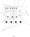
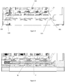
- the figures 1 and 2 represent a schematic view of a set of boxes each comprising at least one electrical device according to an embodiment of the invention.
- the whole figure 1 consists of a box 1 comprising a differential device on the right on the figure 1 and three boxes 2, 2 ', 2 "each comprising a circuit breaker module (or each an electrical device of the circuit breaker or modular circuit breaker type) to the left of the differential module.
- Each box of each modular electrical appliance (or electrical appliance) has a generally parallelepiped appearance and is delimited by two large faces F1 and F2 for example for the differential appliance 1.
- These housings form a row.
- the housing comprising the differential module 1 is positioned on the outside of the assembly, on the right on the figure 1 , and constitutes a first end housing of the assembly.
- this differential device includes a differential measurement toroid T and an actuator (capable of triggering the opening of adjacent devices in the event of a differential fault in the electrical installation to be protected.
- Three boxes 2, 2 ', 2 "circuit breakers phase-neutral type are attached to each other and to the differential module 1 housing by their large parallel faces.
- the circuit breakers D, D ', D "of the figure 1 are phase-neutral magnetothermal type.
- the housing D of the device 2 located at the left end of the row constitutes the other end housing of this row.
- This assembly has input connections E and output connection terminals S.
- the block has the particularity of distributing the 3 input phases L1, L2, L3 after their passage in the differential module , and in particular through the toroid T respectively to each of the three circuit breakers D, D ', D ".
- the neutral N is distributed after its passage in the differential module, in particular through the torus T to each of the three circuit breakers D, D ', D ".
- the neutral is distributed by a mechanical and electrical connection system SD between the output connection terminal of the differential device STN and the input connection terminal of each of the circuit breakers Em.
- the differential device includes a set of four output connection terminals ST1, ST2, ST3, STN, one for each of the three phases L1, L2, L3 and one for neutral N.
- This system thus realizes the distribution of the neutral potential between the terminal of output connection STN of the differential device 1 and the input connection terminals En of circuit breakers D, D ', D "In addition, this includes mechanical connection means (not shown) of the boxes in a row in which their large faces are joined in. In addition, in this embodiment, the assembly is such that the input connection terminals E of the differential module extend over the entire surface of the product thus formed.
- the figure 2 represents an assembly according to another embodiment of the invention similar to that of the figure 1 comprising two housings each comprising a circuit breaker type apparatus and a housing comprising a differential type apparatus.
- Another embodiment of the invention consists of an assembly comprising only boxes, each comprising a device of the circuit breaker type such as those of the figure 1 .
- the input connection terminals E are directly connected to the input connection terminals of the circuit breakers
- the neutral N is distributed to the three circuit breakers by the mechanical and electrical connection system SD which comprises connection means mechanics of the circuit breaker boxes in a row in which their large faces are joined.
- the electrical diagram of the assembly is equivalent to those described above, but the electrical and mechanical connection system distributes one of the phases L1 to L3 and keeps the various housings joined together on their large faces. 2 2 '2 "of the devices constituting said assembly.
- the term distributing a phase between two electrical devices is equivalent to electrically connecting these two devices to the same potential. All conceivable combinations are then possible, the electrical and mechanical connection system being able to distribute, neutral and / or one or more phases.
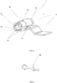
- the figure 3 represents a connector C according to an embodiment of the invention.
- This connector of the connection terminal is intended to be mechanically and electrically connected to a transverse rod 100 identical to those described in Figures 5 to 11 , this transverse rod being intended to be inserted in the connector.
- This connector is made up of two parts, one M having a generally cylindrical appearance or a sleeve intended to receive a transverse rod, the other P forming a radial protrusion of generally planar appearance, in the form of a folded or unfolded tab, and intended to be electrically and / or mechanically connected to the input or output connection terminal of the electrical devices constituting the assembly.
- the arrow F indicates the direction of insertion of the transverse rod into the sleeve.
- the sleeve consists of a sheet of conductive material, rolled on itself in order to form the peripheral wall of the sleeve of general cylindrical appearance M.
- One end of this cylinder has an expandable zone formed, in this example, by 4 tabs 10 each formed between two slots 11, 15 of axial shape formed in the peripheral wall of the sleeve, these tongues being curved towards the axis of the sleeve in order to ensure contact with the transverse rod when the latter is inserted into the sleeve M, in this example this part of the sleeve preferably has a generally frustoconical shape. Optionally (not shown) this shape can also be cylindrical.
- this expendable zone is preferably formed on the side where the transverse rod exits from the sleeve during its insertion, this in order to facilitate the insertion of the transverse rod into the sleeve.
- a chamfer 14 of the same type as the previous one can also be provided at the level of the expandable zones 10, this in order to facilitate the extraction of the transverse rod when the expandable zones are clamped on said rod.
- the sleeve includes 4 tabs.
- This number of expandable tongues can vary from one, two to as many tongues as there are contact points necessary to ensure quality electrical contact between the sleeve and the rod.
- the axial-looking slot 15 formed in the peripheral wall of the sleeve opens at the two ends of the latter, which makes it possible to manufacture the sleeve and the radial protrusion P in one piece.
- the figure 4 presents the connector of the figure 3 in a view along the axis of the sleeve M in the opposite direction to the arrow F.
- the connector is connected by the radial protrusion P to a terminal 16 input or output of an electrical apparatus of the assembly.
- This connection ensures an electrical connection between the two elements, in order to ensure the distribution of the potential of the transverse rod to the electrical device to be supplied, but also a mechanical connection between the connector C and the terminal 16 to ensure the holding C of the connector vis-à-vis the connection terminal when inserting the transverse rod into the sleeve M.
- This connection can conventionally be made by soldering with or without addition of material, by clinching or any other process assembly.
- the transverse rod 100 is in position inserted in the connector C3 and being inserted in the connectors C2 and C1. The direction and direction of insertion being always symbolized by the arrow F.
- the transverse rod is equipped with a head 101 at one of its ends.
- the head 101 has a general shape of a disc perpendicular to the axis of the rod 100, this disc being equipped with a radial groove.
- the conductor 110 is shaped in this example to pass through a measurement toroid T (not shown in this figure) in a device of the differential type.
- the ends 111 and 112 of this conductor are respectively the input and output connection terminals of the differential module.
- the connection terminal 112 corresponds to one of the connection terminals STN of the figure 1 and the connection terminal 111 corresponds to the connection terminal intended for neutral N, of the figure 1 .
- the output connection terminal 112 of the differential device is connected to the head 101 of the rod 100. This connection is provided by soldering, clinching or any other assembly process ensuring a mechanical and electrical connection between these two elements.
- the output terminal 112 of the differential device is preferably connected to the radial rib of the head 101. This link can be produced directly on the head 101 (not shown in this figure).
- a radial rib can also make it possible to block the rod 100 in rotation.
- the head 101 can also be provided with a screw head type imprint.
- the conductor 110 can be flexible or rigid.
- the other end of the rod 100 may be provided with an internal thread intended to receive the screw 102.
- the tightening of the screw 102 in the rod 100 is facilitated by the presence of the radial rib on the head 101 or by any other system allowing the blocking in rotation or the rotary drive of the rod 100 during the tightening of the screw 102 in the rod 100.
- the two elements the rod 100 and the screw 102 ensuring the mechanical maintenance of the housings comprised between the head 101 and the head of the screw 102.
- the electrical connection of the rod to the various devices being carried out by means of three connectors C1, C2, C3 and the head 101 of the rod 100. This connection could also be made by four connectors. Once the rod 100 is inserted into the connectors C1, C2, C3, these can be permanently linked to the rod by a soldering operation. Such an operation ensures an electrical connection between the rod and the various connectors. A clinching operation of the connectors on the rod would have the same effect.
- the figure 6 represents the same embodiment as that of the figure 5 , the rod 100 being in position inserted in the three connectors.
- the figure 10 is a cross section of the assembly of the figure 5 at the axis of the rod 100.
- the hole 103 is threaded to allow the assembly of the screw 102 in the rod 100.
- the rod 100 is in the position inserted in the sleeves of the connectors C1, C2, C3.
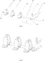
- the figure 11 is a perspective view of a transverse rod 100 according to another embodiment than that presented in the figure 10 .
- the rod 100 is provided with an external thread 104 at one of its ends and the other end is provided with a head 101.
- the thread 104 is intended to be screwed into a barrel of a first housing. .
- This screwing is possible by the presence on the face of the head 101 opposite the rod 100 of means for driving the rod 100 in rotation such as a screwing impression or a hollow or bump radial groove like that of the figure 5 .
- the part of the head 101 on the side of the rod 100 comes at the end of screwing in abutment on a wall of a housing opposite the first.
- the rod 100 allows the tightening of the housings included between the two end housings.
- the conductor 110 is electrically connected to the rod 100 by the connection terminal 112.
- the connection terminal 112 is in the form of a ring.
- the means for fixing the rod to the housings or the different versions of the head of the rod 100 are permutable and constitute only non-limiting examples of the possible solutions for producing these assemblies.
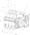
- the figure 7 is a perspective view of an electrical appliance according to the electrical diagram of the figure 1 .
- the outer cover of the differential case being removed.
- An important aspect resides in the fact that normally, such an assembly made up of several housings is mechanically assembled by means of rivets, well known from one skilled in the art. These rivets are slid into the barrels 120 and crimped so as, on the one hand, to hold each unit of the electrical appliance unitarily and on the other hand to hold the housings of the assembly together In this case the electrical distribution of a potential between the different devices must be done outside the volume occupied by the said boxes.
- the electrical and mechanical connection system according to the embodiment has the particularity of occupying the place of one of these assembly rivets, in fact it does not collide with constituent elements of the various electrical modules.
- the system therefore takes up the assembly functions of the various electrical boxes constituting the assembly and it also has the particularity of making it possible to distribute an electrical potential to each of the electrical devices. This potential distribution is carried out via the transverse rod and the various connectors C, C1, C2, C3 present in each device.
- the head 101 which represents the end of the transverse rod housed in one of the assembly drums 120.
- the assembly consisting of three circuit breaker type devices and a differential device whose housing is partially open, has four input connection terminals opening out to the lower surface (inf) of said assembly. These four terminals constitute the four input terminals of the differential device of the assembly according to the embodiment.
- each of these connection terminals has two possible connection points with an external conductor.
- the first of the four input connection terminals corresponding to input E for phase L1 of the figure 1 , has on the underside of the block (Inf) a connection point E11 intended to connect cables with the input connection terminal and a connection point E12 intended to connect rigid conductors of comb type with the terminal input L1.
- each of the input connection terminals may have only one type of connection for cable or bridging comb or may be of the spring type and not of the screw type, all combinations being possible.
- the assembly having the following particularity: the four input connection terminals extend over the entire surface Inf of the assembly constituted by the assembly of the various housings. So on the figure 7 , the connection points E11, E21, E31, E41 extend regularly spaced over the entire lower surface inf of said block. Thus the electrician operator has all this surface in order to be able to connect the various input connection terminals of said differential device to the electrical network. In addition, the input connection terminals being distributed over this entire surface, the maximum size of each conductor to be connected is thus optimized.
- each sleeve M can preferably be positioned in a barrel F made of insulating materials of the plastic type.
- this barrel has a generally hollow cylindrical shape.
- the mechanical connection system is produced by the screw 102, the rod 100 in combination with parts of the housings of the electrical devices constituting said assembly.
- the row of boxes has two end boxes, the first one to the left of the figure 8 and a second on the right of this same figure, opposite the first.
- the screw 102 screwed into the rod 100 comes to bear on a wall 120 of the housing located on the left on the figure 8
- the other end of the rod 100 comprises a head 101 which comes to bear on a wall 121 of the housing located on the right on the figure 8 and opposite the first case cited.
- the pressure generated by this assembly makes it possible to clamp between them all the housings included between the two end housings in a row in which their large faces are joined.
- two adjacent electrical devices for example the two circuit breakers contained in the boxes 2 and 2 ', are separated by a joint part (Int).
- This joint part includes the large consecutive parallel faces and facing these two housings 2 and 2 'in the row of the assembly.
- the two consecutive large parallel faces of these two consecutive boxes 2, 2 ′ of the row of the set being integrated in this adjoining room, the two consecutive and adjacent electrical devices are no longer separated by a double wall, which saves material.
- the Int part can also be positioned between the 2 'and 2 "boxes.
- the two consecutive large parallel faces of these two devices are integrated in this part.
- the figure 12 shows a partial perspective view of an assembly according to an embodiment of the invention from a viewing angle which allows the head of the screw 102 to be seen.
- This screw is accessible through a cylindrical hole 105 opening into a side wall of one of the boxes of the assembly.
- This hole allows, during the assembly of the mechanical and electrical connection system according to the embodiment, to access the head of the screw 102, this in order to carry out the screwing of the screw 102 on the rod 100.
- the hole cylindrical 105 ends with a counterbore which allows the head of the screw 102 to be supported on an end box of the assembly.
- the screw 102 being in contact with the rod 100 which distributes an electrical potential, it is therefore itself at the same electrical potential as that of the rod 100.
- the head of the screw 102 is therefore accessible to a user and presents a risk of electric shock when the apparatuses of the assembly are in service.
- One possible solution is to offset the counterbore from the bottom of the hole 105 so that the head of the screw is no longer accessible by the user's finger. In this case the head of the screw 102 remains always visible to the user and he is protected.
- Another option is the one shown in the figures 13 and 14 .
- the hole 105 is surrounded by a surface 106 parallel to the face of the housing and offset from the latter so as to allow the installation of a shutter 107. Thanks to this surface offset, the surface 106 is set back by relative to the lateral face of the housing, once in place the shutter 107 is flush with the lateral surface of the housing and is thus almost invisible and does not affect the dimension of the row of boxes as can be seen in the figure 14 .
- the shutter has a rectangular shape, the shape of the shutter has no influence on its function from the moment its surface covers the through hole 105.
Landscapes
- Breakers (AREA)
- Details Of Connecting Devices For Male And Female Coupling (AREA)
Description
La présente invention concerne le domaine des produits de protection électriques modulaires unitaires de type interrupteurs, disjoncteurs, blocs différentiels, interrupteur et disjoncteurs différentiels etc...The present invention relates to the field of unitary modular electrical protection products of the switch, circuit breaker, differential block, switch and differential circuit breaker type, etc.
Ces produits peuvent de par leur conception modulaire s'assembler pour offrir un panel de combinaisons de fonctions en un seul appareil dit multi-modulaire permettant de répondre aux différentes normes d'installations électriques.Due to their modular design, these products can be assembled to offer a range of combinations of functions in a single so-called multi-modular device enabling the various standards of electrical installations to be met.
Dans l'assemblage ou le regroupement de produits de protection de type modulaire, il peut être nécessaire de distribuer l'alimentation d'une phase ou du neutre à l'entrée des différents appareils.When assembling or grouping modular type protection products, it may be necessary to distribute the supply of one phase or neutral to the input of the various devices.
Cette fonction de distribution connue est généralement réalisée par un ou des conducteurs rigides reliant les bornes de connexion amont des appareils électrique au même potentiel. Ce ou ces conducteurs d'étendent alors dans leur quasi intégrité à l'extérieur des appareils électriquement reliés, les appareils étant maintenu sur un rail dit « rail modulaire » bien connu de l'homme de l'art.This known distribution function is generally carried out by one or more rigid conductors connecting the upstream connection terminals of the electrical devices to the same potential. This or these conductors then extend in their quasi-integrity outside the electrically connected devices, the devices being held on a rail called "modular rail" well known to those skilled in the art.
Certains regroupements de produits sont demandés par les clients en vue d'une installation plus rapide et standardisée de ces appareils dans le tableau électrique.Certain groupings of products are requested by customers for faster and standardized installation of these devices in the electrical panel.
Dans le cas où le constructeur assure lui-même cette distribution de potentiel, il peut être intéressant alors de l'intégrer dans le volume délimité par les produits et ce dans un double objectif de gain de place et de gain de coût.In the case where the manufacturer himself distributes this potential, it may then be advantageous to integrate it into the volume delimited by the products, with the dual objective of saving space and saving cost.
Lorsque le regroupement touche des produits dans lesquels la fonction principale n'occupe pas la totalité du volume du produit modulaire, comme dans le cas des interrupteurs par exemple qui ne comportent que des contacts, un mécanisme d'ouverture et de fermeture de ces contacts et des bornes de connexion d'entrée et de sortie, il est aisé de trouver un volume dans lequel la distribution amont du courant peut être positionnée. C'est le cas dans le document
Document
Lorsque le regroupement touche des produits plus complexes, le volume disponible pour le passage de ces conducteurs est diminué voire quasi inexistant. De plus, le passage de conducteurs de potentiels différents, par exemple le passage d'un conducteur de phase et d'un conducteur de neutre, impose une distance spécifique dans l'air entre les parties actives de ces conducteurs afin d'éviter le court-circuit entre ces deux conducteur, qui a pour impact d'augmenter le volume nécessaire à leur passage.When the grouping affects more complex products, the volume available for the passage of these conductors is reduced or almost nonexistent. In addition, the passage of conductors of different potentials, for example the passage of a phase conductor and a neutral conductor, imposes a specific distance in the air between the active parts of these conductors in order to avoid short -circuit between these two conductors, which has the impact of increasing the volume necessary for their passage.
L'invention a pour but de résoudre ce problème, à savoir dans un regroupement d'appareils modulaires de type disjoncteur, interrupteur différentiel etc... comment distribuer au moins un même potentiel entre des bornes d'entrée et/ou de sortie des appareils constituants le regroupement dans le volume défini par les appareils modulaires tout en assurant l'intégrité mécanique du bloc ainsi constitué.The object of the invention is to solve this problem, namely in a grouping of modular devices of the circuit breaker, differential switch, etc. type, how to distribute at least the same potential between input and / or output terminals of the devices. constituents grouping in the volume defined by the modular devices while ensuring the mechanical integrity of the block thus formed.
Ce problème est résolu par l'invention et plus particulièrement par un ensemble comprenant une rangée d'au moins deux boîtiers isolants distincts présentant chacun deux grandes faces parallèles et comportant chacun au moins un appareil électrique modulaire par exemple de type disjoncteur, interrupteur, bloc différentiel, chacun desdits appareils électriques comprenant au moins une borne de connexion électrique, caractérisé en ce que ledit ensemble comprend au moins un système de liaison mécanique et électrique reliant mécaniquement lesdits boîtiers entre eux en exerçant en outre un effort presseur, sensiblement perpendiculaire aux deux grandes faces parallèles sur deux boîtiers de la rangée, et en ce que ledit système relie électriquement la ou l'une des borne(s) d'au moins un appareil électrique avec la ou l'une des borne(s) d'un autre appareil électrique afin de distribuer un potentiel électrique entre celles-ci,
et en ce que ledit système est au moins en partie contenu dans le volume défini par les boîtiers.This problem is solved by the invention and more particularly by an assembly comprising a row of at least two separate insulating boxes each having two large parallel faces and each comprising at least one modular electrical appliance, for example of the circuit breaker, switch, differential block type. , each of said electrical devices comprising at least one electrical connection terminal, characterized in that said assembly comprises at least one mechanical and electrical connection system mechanically connecting said boxes between them by also exerting a pressing force, substantially perpendicular to the two large parallel faces on two housings of the row, and in this that said system electrically connects the or one of the terminal (s) of at least one electrical appliance with the or one of the terminal (s) of another electrical appliance in order to distribute an electrical potential therebetween,
and in that said system is at least partly contained in the volume defined by the housings.
Ce lien mécanique entre deux boîtiers de la rangée permet d'assurer le maintien mécanique de tous les appareils électriques modulaires assemblés par le système de liaison mécanique et électrique en un ensemble mécaniquement stable. Un appareil électrique donné du bloc ainsi constitué, ne peut être désassemblé du dit bloc en une simple opération. De plus, même lorsque l'ensemble n'est pas assemblé sur un rail de type « rail modulaire » l'ensemble des appareils se comporte comme un bloc unitaire, l'ensemble est mécanique en un seul composant.This mechanical link between two boxes in the row ensures the mechanical maintenance of all modular electrical devices assembled by the mechanical and electrical connection system in a mechanically stable assembly. A given electrical appliance of the block thus formed cannot be disassembled from the said block in a simple operation. In addition, even when the assembly is not assembled on a rail of the “modular rail” type, the set of devices behaves like a unitary block, the assembly is mechanical in a single component.
Ainsi le système de liaison mécanique et électrique intègre la fonction de fixation en un ensemble des différents appareils électriques auxquels il doit distribuer un potentiel électrique. De plus, le système est au moins en partie contenu dans le volume défini par les appareils électriques afin de dépasser le moins possible du volume défini par les deux appareils et donc de permettre à l'électricien installateur de disposer de plus de volume à l'extérieur des appareils qu'avec un système de pontage classique. Ceci est possible du fait que les deux fonctions, distribution de potentiel et fixation des appareils sont comprises dans le même système de liaison mécanique et électrique.Thus the mechanical and electrical connection system integrates the fixing function into a set of different electrical devices to which it must distribute an electrical potential. In addition, the system is at least partly contained in the volume defined by the electrical devices in order to exceed as little as possible the volume defined by the two devices and therefore to allow the installing electrician to have more volume at the exterior of the devices with a conventional bridging system. This is possible because the two functions, potential distribution and fixing of the devices are included in the same mechanical and electrical connection system.
De préférence les appareils modulaires sont « entiers », c'est-à-dire qu'ils s'étendent dans le volume défini par la norme UTE C 61-920. Ils ne sont pas tronqués afin de permettre le passage d'un quelconque système de pontage dans leur volume.Preferably the modular devices are "whole", that is to say that they extend within the volume defined by the standard UTE C 61-920. They are not truncated in order to allow the passage of any bridging system in their volume.
Préférentiellement, cet ensemble comprend une rangée d'au moins deux boîtiers isolants distincts se caractérisé en ce que ladite rangée comporte deux boîtiers d'extrémité à savoir un premier boîtier d'extrémité à une extrémité de la rangée et un deuxième boîtier d'extrémité à l'autre extrémité de la rangée, ledit système de liaison mécanique et électrique relie mécaniquement lesdits boîtiers entre eux en exerçant en outre un effort presseur, sensiblement perpendiculaire aux deux grandes faces parallèles sur les boîtiers d'extrémités. De ce fait l'effort presseur s'exerce de l'extérieur vers l'intérieur dans l'ensemble de boîtiers de la rangée, ceci afin d'assurer une meilleure cohésion de l'ensemble de boîtiers.Preferably, this assembly comprises a row of at least two separate insulating housings characterized in that said row comprises two end housings, namely a first end housing at one end of the row and a second end housing at the other end of the row, said mechanical and electrical connection system mechanically connects said boxes to each other by exerting a pressing force, substantially perpendicular to the two large parallel faces on the end boxes. As a result, the pressing force is exerted from the outside towards the inside in the set of boxes in the row, this in order to ensure better cohesion of the set of boxes.
Préférentiellement le système de liaison mécanique et électrique est entièrement contenu dans le volume défini par les boîtiers. Ceci afin de permettre à l'électricien installateur de disposer d'un volume à l'extérieur des appareils maximal comparativement avec un système de pontage classique.Preferably, the mechanical and electrical connection system is entirely contained in the volume defined by the boxes. This is to allow the installing electrician to have a maximum volume outside the devices compared to a conventional bridging system.
Optionnellement l'ensemble peut contenir des appareils électriques du type auxiliaire qui ne possède qu'une seule borne de connexion électrique. Ce type d'appareil est en particulier destiné à communiqué à l'utilisateur une information mesurée sur la ligne électrique par le biais de leur unique connexion électrique. Ce type d'appareil peut optionnellement ne pas être muni de borne électrique, par exemple s'il contient un capteur de type capteur de courant sans contact.Optionally, the assembly can contain electrical devices of the auxiliary type which has only one electrical connection terminal. This type of device is in particular intended to communicate to the user information measured on the electrical line by means of their single electrical connection. This type of device may optionally not be fitted with an electrical terminal, for example if it contains a sensor of the contactless current sensor type.
Préférentiellement, l'ensemble est caractérisé en ce que chacun desdits appareils électriques comprend au moins une borne de connexion électrique d'entrée et au moins une borne de connexion électrique de sortie le système de liaison mécanique et électrique reliant électriquement au moins une borne de connexion de sortie d'au moins un premier appareil électrique à au moins une borne de connexion d'entrée d'au moins un autre appareil électrique. C'est-à-dire que la ou les borne(s) de connexion(s) électrique(s) sont réalisée(s) sous la forme de borne(s) de connexion(s) électrique(s) d'entrée et/ou sous la forme de borne(s) de connexion(s) électriques de sortie. Préférentiellement, si l'un des appareils électriques est un appareil de type différentiel, et qu'il est destiné à être assemblé à au moins un appareil de type interrupteur, disjoncteur etc.., l'ensemble permet de relier électriquement la borne de connexion électrique de sortie du premier appareil à la borne de connexion électrique d'entrée l'autre appareil, ou aux entrées des autres appareils. Ainsi le schéma électrique de distribution du potentiel est conforme à ce que demandent les normes d'installation et de plus le système de liaison électrique et mécanique permet l'assemblage mécanique des différents appareils.Preferably, the assembly is characterized in that each of said electrical devices comprises at least one electrical input connection terminal and at least one electrical output connection terminal the mechanical and electrical connection system electrically connecting at least one connection terminal output of at least one first electrical device to at least one input connection terminal of at least one other electrical device. That is to say that the terminal (s) of electrical connection (s) are made (s) in the form of terminal (s) of electrical connection (s) input and / or in the form of electrical connection terminal (s) for output. Preferably, if one of the electrical devices is a device of the differential type, and it is intended to be assembled with at least one device of the switch, circuit breaker type, the assembly makes it possible to connect the connection terminal electrically. output from the first device to the electrical input connection terminal of the other device, or to the inputs of other devices. Thus the electrical diagram of potential distribution is in accordance with what the installation standards require and moreover the electrical and mechanical connection system allows the mechanical assembly of the various devices.
Préférentiellement, l'ensemble se caractérise par le fait que le système de liaison mécanique et électrique relie électriquement au moins deux bornes de connexion électriques d'entrée d'au moins deux appareils électriques. Préférentiellement si les au moins deux appareils à relier électriquement sont du type disjoncteur, interrupteur etc..., l'ensemble permet de relier électriquement les bornes de connexion d'entrée des appareils entre elles au même potentiel. Ainsi le schéma électrique de distribution du potentiel est conforme à ce que demandent les normes d'installation et de plus le système de liaison électrique et mécanique permet l'assemblage mécanique des différents appareils.Preferably, the assembly is characterized in that the mechanical and electrical connection system electrically connects at least two electrical connection terminals for input of at least two electrical devices. Preferably if the at least two devices to be electrically connected are of the circuit breaker, switch etc ... type, the assembly makes it possible to electrically connect the input connection terminals of the devices to each other at the same potential. So the electrical diagram of distribution of the potential complies with what the installation standards require and moreover the electrical and mechanical connection system allows the mechanical assembly of the various devices.
Préférentiellement, l'ensemble se caractérise en ce que le système de liaison mécanique et électrique comprend une tige transversale, chacune des bornes de connexion électrique et/ou bornes de connexion électrique d'entrée et/ou de sortie d'au moins un appareil électrique de l'ensemble comprenant un connecteur interne au(x)dit(s) boîtier(s), la tige étant apte à être connectée aux connecteurs électriques à l'intérieur des boitiersPreferably, the assembly is characterized in that the mechanical and electrical connection system comprises a transverse rod, each of the electrical connection terminals and / or electrical input and / or output connection terminals of at least one electrical appliance. of the assembly comprising an internal connector to the said housing (s), the rod being able to be connected to the electrical connectors inside the housings
Ainsi la distribution du potentiel se fait dans le volume des boîtiers des appareils et n'occupe pas d'espace à l'extérieur de ce volume. De ce fait l'électricien installateur dispose d'un espace maximal à l'extérieur de l'ensemble ainsi constitué. Le fait que cette tige soit transversale aux appareils permet de relier tous les appareils électriques concernés. La distribution du potentiel à chaque appareil se fait par l'intermédiaire d'une liaison électrique à la tige transversale, préférentiellement par des connecteurs. Cette liaison peut être aussi réalisée par brasage d'un conducteur sur le système de liaison mécanique et électrique et plus particulièrement sur la tige transversale ou sur une partie spécifique de celle-ci. Le connecteur peut également être brasé sur la tige transversale ou sur une partie spécifique de celle-ci. Préférentiellement le connecteur est fixe par rapport au(x) dit(s) boîtier(s), ceci afin de permettre un meilleur enfichage de la tige dans le connecteur. Cependant ces connecteurs peuvent également être mobiles par rapport au(x) dit(s) boîtier(s) si l'assemblage tige-connecteur nécessite un mouvement relatif du connecteur par rapport au(x) dit(s) boîtier(s).Thus the distribution of the potential is done in the volume of the housings of the devices and does not occupy space outside this volume. As a result, the installing electrician has maximum space outside the assembly thus formed. The fact that this rod is transverse to the devices makes it possible to connect all the electrical devices concerned. The potential is distributed to each device via an electrical connection to the transverse rod, preferably by connectors. This connection can also be achieved by brazing a conductor on the mechanical and electrical connection system and more particularly on the transverse rod or on a specific part thereof. The connector can also be soldered on the transverse rod or on a specific part thereof. Preferably, the connector is fixed relative to the said housing (s), this in order to allow better insertion of the rod into the connector. However, these connectors can also be movable relative to the said housing (s) if the rod-connector assembly requires relative movement of the connector with respect to the said housing (s).
Préférentiellement, l'ensemble se caractérise également par le fait qu'au moins l'un des connecteurs est constitué d'un manchon conducteur d'allure cylindrique comportant au moins une zone expansible vers l'extérieur sous l'action de la tige transversale au moment de son insertion dans le manchon. Ainsi l'insertion de la tige dans le manchon est possible et la connexion se fait automatiquement au moment de l'insertion, cette zone assurant un effort de contact entre la tige transversale et le manchon conducteur. Préférentiellement, ledit manchon est également doté d'une excroissance extérieure d'allure radiale fixée à une borne d'entrée ou de sortie d'un des appareils électriques, cette excroissance facilite la connexion au circuit électrique de l'appareil électrique à connecter à la tige transversale.Preferably, the assembly is also characterized by the fact that at least one of the connectors consists of a conductive sleeve of cylindrical appearance comprising at least one zone that expands outward under the action of the transverse rod at the when inserted into the sleeve. Thus the insertion of the rod into the sleeve is possible and the connection is made automatically at the time of insertion, this zone ensuring a contact force between the transverse rod and the conductive sleeve. Preferably, said sleeve is also provided with an external protuberance of radial appearance fixed to an input or output terminal of one of the electrical appliances, this protrusion facilitates the connection to the electrical circuit of the electrical device to be connected to the cross rod.
Avantageusement, chaque zone expansible est constituée entre deux fentes d'allure axiale pratiquées dans la paroi périphérique du manchon. Cette réalisation permet d'optimiser la longueur de chaque zone expansible, donc d'optimiser la quantité de matière nécessaire à la réalisation du dit manchon. Préférentiellement cette fente est pratiquée à partir d'une des extrémités du manchon.Advantageously, each expandable zone is formed between two axial-shaped slots made in the peripheral wall of the sleeve. This embodiment makes it possible to optimize the length of each expandable zone, therefore to optimize the amount of material necessary for the production of said sleeve. Preferably, this slot is made from one of the ends of the sleeve.
De préférence, l'une des fentes d'allure axiale est pratiquée jusqu'à déboucher à l'autre extrémité du manchon, l'excroissance extérieure étant d'un seul tenant avec l'un des bords de ladite fente. Cette configuration permet la réalisation du manchon et de l'excroissance extérieure selon une géométrie qui permet la mise à plat de ces deux parties du système. Cette mise à plat est nécessaire à la fabricabilité du manchon et de l'excroissance extérieure d'un seul tenant. Ainsi, grâce à cette disposition, le manchon peut être fabriqué par enroulage autour d'un noyau tout en étant initialement rattaché à l'excroissance. Préférentiellement, le manchon est réduit à sa plus simple expression de tube cylindrique ou d'allure tronconique et l'excroissance extérieure est reportée sur la borne d'entrée ou de sortie à connecter au manchon. Préférentiellement, cette borne est directement liée au manchon.Preferably, one of the axial-looking slots is made until it opens at the other end of the sleeve, the external projection being in one piece with one of the edges of said slot. This configuration allows the realization of the sleeve and the outer protrusion according to a geometry which allows the flattening of these two parts of the system. This flattening is necessary for the manufacture of the sleeve and of the external protuberance in one piece. Thus, thanks to this arrangement, the sleeve can be manufactured by winding around a core while being initially attached to the protrusion. Preferably, the sleeve is reduced to its simplest expression of cylindrical tube or of frustoconical shape and the external protuberance is transferred to the input or output terminal to be connected to the sleeve. Preferably, this terminal is directly linked to the sleeve.
Avantageusement, la ou les zones expansibles sont constituées dans une portion du manchon d'allure tronconique, ce qui permet d'assurer un contact électrique entre la tige transversale et les zones expansibles aux extrémités de ces dernières.Advantageously, the expandable zone or zones are formed in a portion of the frustoconical-looking sleeve, which makes it possible to ensure electrical contact between the transverse rod and the expandable zones at the ends of the latter.
Avantageusement, les deux extrémités axiales du manchon sont chanfreinées, cette configuration permet de facilité l'insertion ou l'extraction de la tige transversale par rapport au connecteur.Advantageously, the two axial ends of the sleeve are chamfered, this configuration makes it easier to insert or extract the transverse rod relative to the connector.
Avantageusement, les manchons sont chacun disposés dans un fût en matériau isolant de type plastique, le fût faisant partie d'un des boîtiers isolant, les zones expansibles étant en pression sur la paroi interne du fût lorsque la tige transversale y est insérée, ainsi la pression de contact entre la tige et les extrémités des manchons est renforcée afin d'obtenir un meilleur contact électrique entre ces deux éléments.Advantageously, the sleeves are each arranged in a barrel of insulating material of the plastic type, the barrel being part of one of the insulating housings, the expandable zones being under pressure on the internal wall of the barrel when the transverse rod is inserted therein, thus the contact pressure between the rod and the ends of the sleeves is reinforced in order to obtain better electrical contact between these two elements.
Avantageusement, la tige transversale comporte, à une extrémité, une tête munie de moyens d'entrainement en rotation de la tige, du type tête de vis par exemple, ladite tête venant en appui contre une paroi latérale d'un boîtier isolant de la rangée, de préférence un des deux boîtiers d'extrémité. Cette tête possède deux fonctions, c'est-à-dire de permettre un appui sur une paroi latérale d'un boîtier de l'ensemble et de permettre l'entrainement en rotation de la tige par des moyens d'entrainement de la tige en rotation tel qu'une fente ou une nervure perpendiculaire à l'axe de la tige par exemple ou par une empreinte de vissage ou tout autre moyen permettant cet entrainement en rotation de la tige.Advantageously, the transverse rod comprises, at one end, a head provided with means for driving the rod in rotation, of the screw head type for example, said head coming to bear against a wall side of an insulating box in the row, preferably one of the two end boxes. This head has two functions, that is to say to allow support on a side wall of a housing of the assembly and to allow the rod to be rotated by means of the rod driving means. rotation such as a slot or a rib perpendicular to the axis of the rod for example or by a screwing impression or any other means allowing this rotational training of the rod.
Avantageusement, la tige transversale comporte une partie d'extrémité filetée, opposée à l'emplacement de la tête, destinée à se visser dans un filetage situé dans une paroi latérale de l'un parmi les boîtiers isolants. Préférentiellement, lorsque la tige transversale est en position d'assemblage d'au moins deux appareils électriques contenus dans deux boîtiers isolants dans une rangée, la tête de la tige transversale est en appui sur une paroi d'un premier boîtier d'extrémité et la partie filetée de la tige est vissée dans un filetage situé dans une paroi latérale de l'autre boîtier d'extrémité. Préférentiellement, le filetage est borgne afin d' éviter tout accès par l'extérieur de l'ensemble à une pièce sous tension. Ainsi la tige transversale peut être fixée mécaniquement par vissage à l'un des boîtiers d'extrémité et maintenir un effort presseur dirigé le long de la dite tige sur l'autre boîtier d'extrémité. Ainsi, selon la direction de cet effort et de par le fait que la tige est transversale aux boîtiers, tous les boîtiers constituants l'ensemble sont maintenus de telle sorte que leurs grandes faces sont accolées.Advantageously, the transverse rod has a threaded end portion, opposite the location of the head, intended to be screwed into a thread located in a side wall of one of the insulating housings. Preferably, when the transverse rod is in the assembly position of at least two electrical devices contained in two insulating housings in a row, the head of the transverse rod is supported on a wall of a first end housing and the threaded part of the rod is screwed into a thread located in a side wall of the other end housing. Preferably, the thread is blind in order to avoid any access from the outside of the assembly to a live part. Thus, the transverse rod can be mechanically fixed by screwing to one of the end boxes and maintain a pressing force directed along said rod on the other end box. Thus, according to the direction of this effort and by the fact that the rod is transverse to the housings, all the housings constituting the assembly are held so that their large faces are joined.
Préférentiellement, la tige transversale comporte une partie d'extrémité filetée à l'intérieur de la tige, opposée à la tête de la tige, ledit ensemble comprenant en outre une vis reçue dans la partie d'extrémité filetée, la vis s'appuyant sur une paroi latérale de l'un parmi les boîtiers isolants.Preferably, the transverse rod has a threaded end part inside the rod, opposite the head of the rod, said assembly further comprising a screw received in the threaded end part, the screw resting on a side wall of one of the insulating boxes.
Dans cette variante, l'assemblage de l'ensemble est équivalent à celui décrit ci-dessus. La tête de la tige transversale est en appui sur une paroi d'un premier boîtier d'extrémité et la vis qui s'insère dans la partie filetée de la tige est en appui sur une paroi latérale de l'autre boîtier d'extrémité de l'ensemble. Ainsi, la tige transversale peut être fixée mécaniquement par vissage à l'un des boîtiers d'extrémité afin de maintenir un effort presseur dirigé le long de la dite tige sur l'autre boîtier d'extrémité via la tête de la tige. Ainsi, selon la direction de cet effort et de par le fait que la tige est transversale aux boîtiers de l'ensemble, tous les boîtiers constituants l'ensemble sont maintenus de telle sorte que leurs grandes faces sont accolées.In this variant, the assembly of the assembly is equivalent to that described above. The head of the transverse rod is supported on a wall of a first end housing and the screw which is inserted in the threaded part of the rod is supported on a side wall of the other end housing all. Thus, the transverse rod can be mechanically fixed by screwing to one of the end boxes in order to maintain a pressing force directed along said rod on the other end box via the head of the rod. Thus, according to the direction of this effort and by the fact that the rod is transverse to the housings of the assembly, all the housings constituents the whole are maintained so that their large faces are joined.
Ces deux configurations permettent un serrage des boîtiers compris entre la tête de la tige transversale et sa partie fileté, ce serrage étant exercé longitudinalement par rapport à la tige et permettant le maintien des appareils électriques de telle sorte que leurs grandes faces sont accolées.These two configurations allow tightening of the housings comprised between the head of the transverse rod and its threaded part, this tightening being exerted longitudinally with respect to the rod and allowing the maintenance of electrical apparatuses so that their large faces are joined.
Préférentiellement, l'un des appareils électriques est un module différentiel comportant au moins une borne de connexion électrique de sortie, l'un au moins parmi les autres appareils électriques étant un disjoncteur comportant au moins une borne de connexion électrique d'entrée, le système de liaison mécanique et électrique reliant une borne de connexion électrique de sortie à au moins une borne de connexion électrique d'entrée.Preferably, one of the electrical devices is a differential module comprising at least one electrical output connection terminal, at least one of the other electrical devices being a circuit breaker comprising at least one electrical input connection terminal, the system mechanical and electrical connection connecting an electrical output connection terminal to at least one electrical input connection terminal.
Cette configuration permet avantageusement de réaliser un appareillage monobloc du type disjoncteur différentiel ou interrupteur différentiel sur la base de deux types de modules existant, l'assemblage et le maintien mécanique de ces modules entre eux étant réalisé par le système de liaison mécanique et électrique, ce système assurant la distribution d'un potentiel de la sortie du module de type différentiel à l'entrée d'au moins un module de type disjoncteur. Cette configuration permet avantageusement de disposer le système de liaison mécanique et électrique à l'intérieur du volume occupé par les différents modules constituant l'ensemble libérant ainsi l'espace extérieur aux modules pour le passage d'autres éléments de l'installation électrique dans laquelle l'ensemble est installé, tel de des câbles par exemple. Cette configuration permet également une industrialisation aisée de l'assemblage de ces ensembles puisque l'assemblage mécanique et la distribution du potentiel (liaison électrique) sont assurés par le seul système de liaison mécanique et électrique, et comme ce système est intégré au volume des boîtiers, l'encombrement de l'ensemble est optimisé, donc la manipulation des ensembles assemblés est facilitée.This configuration advantageously makes it possible to produce a one-piece switchgear of the differential circuit breaker or differential switch type on the basis of two types of existing modules, the assembly and mechanical maintenance of these modules between them being carried out by the mechanical and electrical connection system, this system ensuring the distribution of a potential from the output of the differential type module to the input of at least one circuit breaker type module. This configuration advantageously makes it possible to have the mechanical and electrical connection system inside the volume occupied by the various modules constituting the assembly thus freeing up the space outside the modules for the passage of other elements of the electrical installation in which the assembly is installed, such as cables for example. This configuration also allows easy industrialization of the assembly of these assemblies since the mechanical assembly and the distribution of the potential (electrical connection) are ensured by the only mechanical and electrical connection system, and as this system is integrated into the volume of the housings , the overall dimensions of the assembly are optimized, so the handling of the assembled assemblies is facilitated.
Préférentiellement, l'ensemble est caractérisé en ce qu'il comprend quatre appareils électriques par exemple de type disjoncteur, interrupteur, bloc différentiel et en ce que l'un des appareils électriques est un module différentiel comportant au moins une borne de connexion électrique de sortie, les trois autres appareils électriques étant des disjoncteurs comportant chacun au moins une borne de connexion électrique d'entrée, le système de liaison mécanique et électrique reliant au moins une borne de connexion électrique de sortie à moins une borne de connexion électrique d'entrée de chacun des disjoncteurs afin de distribuer un potentiel électrique entre celles-ci. Avantageusement cette configuration correspond à un cas de montage très répandu, de ce fait l'électricien monteur n'a plus à câbler individuellement les différents appareils entre eux, il se contente d'installer directement l'ensemble dans l'installation électrique et gagne ainsi un temps précieux. Préférentiellement, l'ensemble comporte un module différentiel et trois modules disjoncteurs.Preferably, the assembly is characterized in that it comprises four electrical devices, for example of the circuit breaker, switch, differential block type, and in that one of the electrical devices is a differential module comprising at least one electrical output connection terminal. , the other three electrical appliances being circuit breakers each comprising at least one electrical input connection terminal, the mechanical and electrical connection system connecting at least one electrical output connection terminal to at least one electrical input connection terminal of each of the circuit breakers in order to distribute a potential electric between them. Advantageously, this configuration corresponds to a very widespread mounting case, therefore the assembling electrician no longer has to individually wire the various devices to each other, he is content to install the assembly directly in the electrical installation and thus gains precious time. Preferably, the assembly includes a differential module and three circuit breaker modules.
Préférentiellement, les disjoncteurs sont du type phase-neutre.Preferably, the circuit breakers are of the phase-neutral type.
Préférentiellement, seul le neutre est distribué par le système de liaison mécanique et électrique. Préférentiellement, l'ensemble ainsi constitué est caractérisé en ce que les bornes électriques d'entrée du module différentiel s'étendent sur toute une face de l'ensemble, ainsi l'opérateur électricien dispose de toute cette surface afin de pouvoir connecter les différentes entrées dudit appareil différentiel au réseau électrique. De plus, les bornes d'entrée étant réparties sur toute cette surface, la taille maximum de chaque conducteur à connecter est ainsi optimisée.Preferably, only the neutral is distributed by the mechanical and electrical connection system. Preferably, the assembly thus formed is characterized in that the electrical input terminals of the differential module extend over an entire face of the assembly, so the electrician operator has all this surface in order to be able to connect the various inputs of said differential device to the electrical network. In addition, the input terminals being distributed over this entire surface, the maximum size of each conductor to be connected is thus optimized.
Préférentiellement, les deux grandes faces parallèles d'au moins deux boîtiers consécutifs de la rangée, consistent en une pièce mitoyenne aux deux dits boîtiers consécutifs de la rangée. Ainsi le gain de matière réalisé par l'intégration de ces deux faces dans le même élément mitoyen permet une optimisation économique de l'ensemble.Preferably, the two large parallel faces of at least two consecutive boxes of the row, consist of a part adjoining the two said consecutive boxes of the row. Thus the material gain achieved by the integration of these two faces in the same adjoining element allows economic optimization of the whole.
D'autres buts, caractéristiques et avantages apparaîtront à la lecture de la description suivante qui se réfère aux figures annexées représentant des modes de réalisation préférentiels de l'invention, donnés uniquement à titre d'exemples non limitatifs, et dans lesquelles :
- La
figure 1 est une vue schématique d'un ensemble selon un mode de réalisation de l'invention comportant un module différentiel et trois modules disjoncteur de type phase neutre. - La
figure 2 est une vue schématique d'un ensemble selon un mode de réalisation de l'invention comportant un module différentiel et deux modules disjoncteurs de type phase neutre. - La
figure 3 est une vue en perspective d'un connecteur selon un mode de réalisation de l'invention. - La
figure 4 est une vue dans l'axe du connecteur selon un mode de réalisation de l'invention, le connecteur étant relié à une borne de connexion d'entrée (ou de sortie) d'un appareil électrique du système. - La
figure 5 est une perspective présentant l'agencement entre les bornes de connexion et la tige transversale dans un ensemble où la tige transversale distribue un potentiel à ces trois bornes de connexion. - La
figure 6 est une vue agrandie de lafigure 5 dans laquelle la tige transversale est insérée dans les trois bornes de connexion. - La
figure 7 représente un ensemble selon un mode de réalisation de l'invention en perspective, un couvercle de l'un des boîtiers de l'ensemble étant enlevé. - La
figure 8 est une section (non hachurée) du bloc de lafigure 7 le long de l'axe de la tige transversale selon le plan de la face avant de l'ensemble. - La
figure 9 est la même section que celle de lafigure 8 mais hachurée. - La
figure 10 est une section transversale de l'assemblage de lafigure 5 . - La
figure 11 est une vue en perspective de la tige transversale selon un autre mode de réalisation. - La
figure 12 est une vue partielle en perspective d'un ensemble selon l'invention. - Les
figures 13 et14 sont des vues partielles en perspective d'un détail de lafigure 12 .
- The
figure 1 is a schematic view of an assembly according to an embodiment of the invention comprising a differential module and three circuit breaker modules of the neutral phase type. - The
figure 2 is a schematic view of an assembly according to an embodiment of the invention comprising a differential module and two circuit breaker modules of the neutral phase type. - The
figure 3 is a perspective view of a connector according to an embodiment of the invention. - The
figure 4 is a view in the axis of the connector according to an embodiment of the invention, the connector being connected to an input (or output) connection terminal of an electrical appliance of the system. - The
figure 5 is a perspective showing the arrangement between the connection terminals and the transverse rod in an assembly where the transverse rod distributes a potential to these three connection terminals. - The
figure 6 is an enlarged view of thefigure 5 in which the cross rod is inserted into the three connection terminals. - The
figure 7 shows an assembly according to an embodiment of the invention in perspective, a cover of one of the housings of the assembly being removed. - The
figure 8 is a section (not hatched) of the block of thefigure 7 along the axis of the transverse rod along the plane of the front face of the assembly. - The
figure 9 is the same section as that of thefigure 8 but hatched. - The
figure 10 is a cross section of the assembly of thefigure 5 . - The
figure 11 is a perspective view of the transverse rod according to another embodiment. - The
figure 12 is a partial perspective view of an assembly according to the invention. - The
figures 13 and14 are partial perspective views of a detail of thefigure 12 .
Le but d'un ensemble de boîtiers comportant des appareils électriques selon l'invention est de protéger les biens et/ou les personnes par exemple. Pour ce faire l'appareil électrique, ou le bloc ainsi constitué se positionne en amont d'une ligne électrique à protéger. Selon les fonctions de l'appareil plusieurs types de défauts peuvent être détectés et la ligne à protéger est alors ouverte par l'appareil.The purpose of a set of boxes comprising electrical devices according to the invention is to protect property and / or people for example. To do this, the electrical device, or the block thus formed, is positioned upstream of an electrical line to be protected. Depending on the functions of the device, several types of fault can be detected and the line to be protected is then opened by the device.
Les
La
Un autre mode de réalisation de l'invention non représenté consiste en un ensemble ne comprenant que des boîtiers comprenant chacun un appareil de type disjoncteur comme ceux de la
Dans un autre mode de réalisation de l'invention, le schéma électrique de l'ensemble est équivalent à ceux décrits précédemment, mais le système de liaison électrique et mécanique distribuée une des phases L1 à L3 et maintient accolés sur leurs grandes faces les différents boîtiers 2 2' 2" des appareils constituants ledit ensemble. Le terme distribuer une phase entre deux appareils électrique est équivalent à relier électriquement ces deux appareils au même potentiel. Toutes les combinaisons imaginables sont alors possible, le système de liaison électrique et mécanique pouvant distribuer, le neutre et/ou une ou plusieurs phases.In another embodiment of the invention, the electrical diagram of the assembly is equivalent to those described above, but the electrical and mechanical connection system distributes one of the phases L1 to L3 and keeps the various housings joined together on their large faces. 2 2 '2 "of the devices constituting said assembly. The term distributing a phase between two electrical devices is equivalent to electrically connecting these two devices to the same potential. All conceivable combinations are then possible, the electrical and mechanical connection system being able to distribute, neutral and / or one or more phases.
La
La
Dans la
La
La
La
Préférentiellement, les moyens de fixation de la tige aux boîtiers ou les différentes versions de la tête de la tige 100 sont permutables et ne constituent que des exemples non limitatifs des solutions possibles pour réaliser ces assemblages.Preferably, the means for fixing the rod to the housings or the different versions of the head of the
La
Sur la
Sur les
Sur ces figures, le système de liaison mécanique est réalisé par la vis 102, la tige 100 en combinaison avec des parties des boîtiers des appareils électriques constituants ledit ensemble. La rangée des boîtiers comporte deux boîtiers d'extrémité, un premier à gauche de la
Dans le mode de réalisation de la
La
La vis 102 étant en contact avec la tige 100 qui distribue un potentiel électrique, elle est de ce fait elle-même au même potentiel électrique que celui de la tige 100. Comme le trou 105 est débouchant sur une paroi extérieure d'un boîtier de l'ensemble, la tête de la vis 102 est donc accessible pour un utilisateur et présente un risque de choc électrique lorsque les appareils de l'ensemble sont en service. Une solution possible est de décaler le lamage du fond du trou 105 afin que la tête de la vis ne soit plus accessible par le doigt de l'utilisateur. Dans ce cas la tête de la vis 102 reste toujours visible pour l'utilisateur et il est protéger. Une autre option est celle qui est représentée aux
Bien entendu, l'invention n'est pas limitée au mode de réalisation décrit et représenté aux dessins annexés. Des modifications restent possibles, notamment du point de vue de la constitution des divers éléments, par combinaison différente des caractéristiques présentées ci-dessus, ou par substitution d'équivalents techniques, sans sortir pour autant du domaine de protection de l'invention.Of course, the invention is not limited to the embodiment described and shown in the accompanying drawings. Modifications remain possible, in particular from the point of view of the constitution of the various elements, by a different combination of the characteristics presented above, or by substitution of technical equivalents, without thereby departing from the scope of protection of the invention.
Claims (20)
- Assembly comprising a row of at least two separate insulating housings (1, 2, 2', 2") each having two large parallel faces (F1, F2) and each having at least one modular electrical device, for example a circuit breaker, switch or differential unit, each of said electrical devices comprising at least one electrical connection terminal (Em, L1, L2, L3, L4, ST), said assembly comprising at least one mechanical and electrical connection system (SD, 100, 101, 102) mechanically connecting said housings to one another,
said system electrically connecting the or one of the terminal (s) (ST, EM, L1, L2, L3, L4, 16) of at least one electrical device to the or one of the terminal (s) of another electrical device in order to distribute an electrical potential between them,
and said system being at least partly contained within the volume defined by the housings,
characterized in that said mechanical and electrical connection system (SD, 100, 101, 102) mechanically connects said housings to one another by exerting a pressing force substantially perpendicular to the two large parallel faces (F1, F2) on two housings of the row. - Assembly comprising a row of at least two separate insulating housings according to the preceding claim, characterized in that said row has two end housings (1, 2), namely a first end housing (1) at one end of the row and a second end housing (2) at the other end of the row,
said mechanical and electrical connection system (SD, 100, 101, 102) mechanically connects said housings to one another by furthermore exerting a pressing force substantially perpendicular to the two large parallel faces (F1, F2) on the end housings. - Assembly according to either one of the preceding claims, characterized in that the mechanical and electrical connection system (SD, 100, 101, 102) is contained entirely within the volume defined by the housings.
- Assembly according to any one of the preceding claims, characterized in that each of said electrical devices comprises at least one input electrical connection terminal and at least one output electrical connection terminal, the mechanical and electrical connection system (SD, 100, 101, 102) electrically connecting at least one output connection terminal (112) of at least one first electrical device to at least one input connection terminal (Em, 16, 111) of at least one other electrical device.
- Assembly according to any one of Claims 1 to 3, characterized in that each of said electrical devices comprises at least one input electrical connection terminal and at least one output electrical connection terminal, in that the mechanical and electrical connection system (SD, 100, 101, 102) electrically connects at least two input electrical connection terminals (Em, 16, 111) of at least two electrical devices.
- Assembly according to any one of the preceding claims, characterized in that the mechanical and electrical connection system (SD, 100, 101, 102) comprises a transverse rod (100), each of the input and/or output electrical connection terminals of at least one electrical device of the assembly comprising a connector (C, 112) internal to said housing(s), the rod (100) being able to be connected to the electrical connectors (C, 112) inside the housings.
- Assembly according to the preceding claim, characterized in that at least one of the connectors (C, 112) is soldered to the mechanical and electrical connection system (SD, 100, 101, 102), preferably to the transverse rod (100).
- Assembly according to either one of Claims 6 and 7, characterized in that at least one of the connectors (C) consists of a cylindrical conductive sleeve (M) having at least one expandable area (10) able to expand outwardly under the action of the transverse rod (100) when it is inserted into the sleeve, said sleeve (M) also being provided with a radial external protuberance (P) fastened to an input or output terminal of one of the electrical devices.
- Assembly according to the preceding claim, characterized in that each expandable area (10) is formed between two axial slots (11) formed in the peripheral wall of the sleeve (M).
- Assembly according to the preceding claim, characterized in that one of the axial slots (15) is formed to the point of opening out at the two ends of the sleeve (M), the external protuberance (P) being integral with one of the edges of said slot.
- Assembly according to one of Claims 8 to 10, characterized in that the expandable area or areas (10) are formed in a frustoconical portion of the sleeve (M) .
- Assembly according to one of Claims 8 to 11, characterized in that the two axial ends of the sleeve are chamfered (12, 14).
- Assembly according to one of Claims 8 to 12, characterized in that the sleeves (M) are each positioned in a barrel (F) made from insulating plastic material, the barrel (F) forming part of one of the insulating housings, the expandable areas (10) being pressed against the internal wall of the barrel when the transverse rod (100) is inserted thereinto.
- Assembly according to one of Claims 6 to 13, characterized in that the transverse rod (100) has, at one end, a head (101) provided with means for driving the rod in rotation, such as for example a screw head, said head (101) bearing against a side wall (121) of an insulating housing of the row, preferably one of the two end housings (1, 2).
- Assembly according to one of Claims 6 to 14, characterized in that the transverse rod (100) has a threaded end portion (104), opposite the location of the head (101) and intended to screw into a thread situated in a side wall of one of the insulating housings (1, 2, 2', 2").
- Assembly according to one of Claims 6 to 14, characterized in that the transverse rod (100) has a threaded end portion inside the rod (103), opposite the head of the rod (101), said assembly furthermore comprising a screw (102) received in the threaded end portion, the screw (102) bearing on a side wall (120) of one of the insulating housings (1, 2, 2', 2").
- Assembly according to any one of the preceding claims, characterized in that one of the electrical devices is a differential module (1) having at least one output electrical connection terminal (ST, 112), at least one of the other electrical devices being a circuit breaker (2) having at least one input electrical connection terminal (Em, 16), the mechanical and electrical connection system (SD, 100, 101, 102) connecting an output electrical connection terminal (ST, 112) to at least one input electrical connection terminal (Em, 16).
- Assembly according to the preceding claim, characterized in that it comprises four electrical devices, for example circuit breakers, switches or differential units, and in that one of the electrical devices is a differential module (1) having at least one output electrical connection terminal (ST, 112), the other three electrical devices being circuit breakers (2, 2', 2") each having at least one input electrical connection terminal (Em, 16), the mechanical and electrical connection system (SD, 100, 101, 102) connecting an output electrical connection terminal (ST, 112) to at least one input electrical connection terminal (Em, 16) of each of the circuit breakers in order to distribute an electrical potential between them.
- Assembly according to either of Claims 17 and 18, characterized in that the input electrical terminals (E11, E21, E31, E41) of the differential module extend over a whole face (inf) of the assembly.
- Assembly according to any one of the preceding claims, characterized in that the two large parallel faces (F1, F2) of at least two consecutive housings of the row (2, 2'), (2', 2"), (2", 1) consist of a common component (Int) shared between the two said consecutive housings of the row.
Applications Claiming Priority (2)
| Application Number | Priority Date | Filing Date | Title |
|---|---|---|---|
| FR1557439A FR3039698B1 (en) | 2015-07-31 | 2015-07-31 | ASSEMBLY OF ELECTRICALLY CONNECTED AND ELECTRICALLY CONNECTED ELECTRICAL EQUIPMENT HOUSINGS |
| PCT/FR2016/051957 WO2017021623A1 (en) | 2015-07-31 | 2016-07-28 | Assembly of mechanically and electrically interconnected electrical device casings |
Publications (2)
| Publication Number | Publication Date |
|---|---|
| EP3300530A1 EP3300530A1 (en) | 2018-04-04 |
| EP3300530B1 true EP3300530B1 (en) | 2020-02-19 |
Family
ID=55345895
Family Applications (1)
| Application Number | Title | Priority Date | Filing Date |
|---|---|---|---|
| EP16756726.2A Active EP3300530B1 (en) | 2015-07-31 | 2016-07-28 | Assembly of mechanically and electrically interconnected electrical device casings |
Country Status (4)
| Country | Link |
|---|---|
| EP (1) | EP3300530B1 (en) |
| CN (1) | CN107924793B (en) |
| FR (1) | FR3039698B1 (en) |
| WO (1) | WO2017021623A1 (en) |
Families Citing this family (2)
| Publication number | Priority date | Publication date | Assignee | Title |
|---|---|---|---|---|
| CN108054067A (en) * | 2017-12-06 | 2018-05-18 | 俊朗电气有限公司 | A kind of small-sized automatic reclosing |
| FR3103626B1 (en) * | 2019-11-21 | 2022-07-08 | Hager Electro Sas | Electromechanical system for interrupting an electric current |
Family Cites Families (8)
| Publication number | Priority date | Publication date | Assignee | Title |
|---|---|---|---|---|
| DE7105414U (en) * | 1971-02-13 | 1971-05-06 | Bbc Ag | Multipole residual current circuit breaker |
| CH672859A5 (en) * | 1987-03-27 | 1989-12-29 | Maier & Cie C | Terminal arrangement for fault protection switch - has input current terminals and neutral terminals in separate planes w.r.t. front face |
| FR2841376B1 (en) * | 2002-06-25 | 2004-08-06 | Schneider Electric Ind Sa | ELECTROMAGNETIC PROTECTION AND CONTROL ASSEMBLY |
| DE60227086D1 (en) | 2002-12-20 | 2008-07-24 | Hager Electro | Electrical device, for example modular electrical device with a two-part housing |
| PL2019407T3 (en) * | 2007-07-26 | 2010-10-29 | Bticino Spa | Residual current device for an electric circuit breaker |
| JP5084779B2 (en) * | 2008-11-27 | 2012-11-28 | 東京エレクトロン株式会社 | Plug-in unit |
| US9196441B2 (en) * | 2013-04-19 | 2015-11-24 | Abl Ip Holding Llc | Modular relay sub-assembly |
| US9814146B2 (en) * | 2013-08-23 | 2017-11-07 | Mitsubishi Electric Corporation | Drive apparatus |
-
2015
- 2015-07-31 FR FR1557439A patent/FR3039698B1/en not_active Expired - Fee Related
-
2016
- 2016-07-28 WO PCT/FR2016/051957 patent/WO2017021623A1/en active Application Filing
- 2016-07-28 EP EP16756726.2A patent/EP3300530B1/en active Active
- 2016-07-28 CN CN201680043787.7A patent/CN107924793B/en active Active
Non-Patent Citations (1)
| Title |
|---|
| None * |
Also Published As
| Publication number | Publication date |
|---|---|
| FR3039698A1 (en) | 2017-02-03 |
| CN107924793B (en) | 2020-04-07 |
| WO2017021623A1 (en) | 2017-02-09 |
| FR3039698B1 (en) | 2019-08-30 |
| EP3300530A1 (en) | 2018-04-04 |
| CN107924793A (en) | 2018-04-17 |
Similar Documents
| Publication | Publication Date | Title |
|---|---|---|
| CA2871272C (en) | Energy storage module containing a plurality of energy storage elements and improved means of thermal dissipation and method of assembly | |
| EP1376638B1 (en) | Electromagnetic protection and control assembly | |
| EP3300530B1 (en) | Assembly of mechanically and electrically interconnected electrical device casings | |
| EP2299552A1 (en) | Box intended to receive a low-voltage electrical device associated with a medium-voltage switchgear cell | |
| EP2146400B1 (en) | Connection unit and method for mounting such a connection unit | |
| EP0805605A1 (en) | Interconnecting device for transmission networks, especially for telephony and data processing | |
| EP2849295B1 (en) | Electric distribution assembly comprising a multipole electric power distribution comb. | |
| EP2662931B1 (en) | Connection tip for insulated power-supply cable and method for manufacturing said connection tip | |
| FR2919764A1 (en) | DEVICE FOR ELECTRICALLY CONNECTING BETWEEN TWO MEDIUM OR HIGH VOLTAGE CELLS AND DISTRIBUTION POST HAVING AT LEAST ONE SUCH DEVICE | |
| EP3409084B1 (en) | Wiring harness connection plate | |
| FR2797353A1 (en) | Connector for electric conductors e.g. for motor vehicles, has at least one electrically conductive bridge with as many end sections as electric conductors to be connected | |
| FR2926393A1 (en) | Voltage trigger's electronic module case for e.g. three-pole circuit breaker, has box to house actuator in rest position at inside of case and in active position, in which actuator protrudes out from case by orifice and recess of lid | |
| FR2900508A1 (en) | Metallic power distribution bus-bar for e.g. circuit-breaker, has connection units between connection terminal and stud, and allowing two configurations in which operating unit is in sides of corresponding main surfaces, respectively | |
| FR2811812A1 (en) | CONNECTION CONNECTOR AND ELECTRICAL CONNECTION ASSEMBLY BETWEEN A SET OF BARS AND AT LEAST ONE CONDUCTIVE CABLE | |
| FR3002088A1 (en) | Electrical contact for socket-outlet for e.g. dwelling, has cell extending according to perpendicular direction with respect to longitudinal axis when part is encased in another part | |
| EP3349305A1 (en) | Improved electrical connection kit | |
| EP3435398B1 (en) | Differential electrical protection apparatus | |
| EP3312948B1 (en) | Electric socket comprising a one-piece part for supporting and receiving cells and method for assembling such an electric socket | |
| FR2802024A1 (en) | MODULAR SINGLE POLE DISTRIBUTOR AND CONNECTION BLOCK FOR SUCH A DISTRIBUTOR | |
| EP3109943A1 (en) | Electric connection device for an electrical appliance | |
| EP2068411A1 (en) | Embedded electrical appliance with quick connection | |
| FR3010240A1 (en) | ELECTRICAL DEVICE COMPRISING AN ELECTRIC CIRCUIT PRINTED ON A SUPPORT PLATE AND AN ELECTRICAL CONNECTION TERMINAL | |
| FR3084211A1 (en) | ELECTRICAL POWER CONNECTION ASSEMBLY FOR CONNECTING ELECTRICAL CABLES TO AN AIRCRAFT ELECTRIC HEART AND CORRESPONDING ELECTRICAL POWER SYSTEM | |
| FR2948823A1 (en) | Connector for cut false grate of electrical network of connection box in individual installation i.e. house, has derivation bar provided with block that defines housing of receiving, blocking and connection of end of intermediate cable | |
| FR2528623A1 (en) | Series of electrical isolating switches with common exterior size - use operating arms carrying cartridge fuses which are externally accessible with switches are open |
Legal Events
| Date | Code | Title | Description |
|---|---|---|---|
| STAA | Information on the status of an ep patent application or granted ep patent |
Free format text: STATUS: THE INTERNATIONAL PUBLICATION HAS BEEN MADE |
|
| PUAI | Public reference made under article 153(3) epc to a published international application that has entered the european phase |
Free format text: ORIGINAL CODE: 0009012 |
|
| STAA | Information on the status of an ep patent application or granted ep patent |
Free format text: STATUS: REQUEST FOR EXAMINATION WAS MADE |
|
| 17P | Request for examination filed |
Effective date: 20171228 |
|
| AK | Designated contracting states |
Kind code of ref document: A1 Designated state(s): AL AT BE BG CH CY CZ DE DK EE ES FI FR GB GR HR HU IE IS IT LI LT LU LV MC MK MT NL NO PL PT RO RS SE SI SK SM TR |
|
| AX | Request for extension of the european patent |
Extension state: BA ME |
|
| RIN1 | Information on inventor provided before grant (corrected) |
Inventor name: SCHMITT, CEDRIC Inventor name: HECHT, JEAN GEORGES Inventor name: CHARLES, BENJAMIN |
|
| RAP1 | Party data changed (applicant data changed or rights of an application transferred) |
Owner name: HAGER-ELECTRO SAS |
|
| DAV | Request for validation of the european patent (deleted) | ||
| DAX | Request for extension of the european patent (deleted) | ||
| GRAP | Despatch of communication of intention to grant a patent |
Free format text: ORIGINAL CODE: EPIDOSNIGR1 |
|
| STAA | Information on the status of an ep patent application or granted ep patent |
Free format text: STATUS: GRANT OF PATENT IS INTENDED |
|
| INTG | Intention to grant announced |
Effective date: 20191111 |
|
| GRAS | Grant fee paid |
Free format text: ORIGINAL CODE: EPIDOSNIGR3 |
|
| GRAA | (expected) grant |
Free format text: ORIGINAL CODE: 0009210 |
|
| STAA | Information on the status of an ep patent application or granted ep patent |
Free format text: STATUS: THE PATENT HAS BEEN GRANTED |
|
| AK | Designated contracting states |
Kind code of ref document: B1 Designated state(s): AL AT BE BG CH CY CZ DE DK EE ES FI FR GB GR HR HU IE IS IT LI LT LU LV MC MK MT NL NO PL PT RO RS SE SI SK SM TR |
|
| REG | Reference to a national code |
Ref country code: CH Ref legal event code: EP |
|
| REG | Reference to a national code |
Ref country code: DE Ref legal event code: R096 Ref document number: 602016030126 Country of ref document: DE |
|
| REG | Reference to a national code |
Ref country code: AT Ref legal event code: REF Ref document number: 1235908 Country of ref document: AT Kind code of ref document: T Effective date: 20200315 |
|
| REG | Reference to a national code |
Ref country code: IE Ref legal event code: FG4D Free format text: LANGUAGE OF EP DOCUMENT: FRENCH |
|
| REG | Reference to a national code |
Ref country code: NL Ref legal event code: FP |
|
| REG | Reference to a national code |
Ref country code: CH Ref legal event code: NV Representative=s name: DR. GRAF AND PARTNER AG INTELLECTUAL PROPERTY, CH |
|
| PG25 | Lapsed in a contracting state [announced via postgrant information from national office to epo] |
Ref country code: RS Free format text: LAPSE BECAUSE OF FAILURE TO SUBMIT A TRANSLATION OF THE DESCRIPTION OR TO PAY THE FEE WITHIN THE PRESCRIBED TIME-LIMIT Effective date: 20200219 Ref country code: NO Free format text: LAPSE BECAUSE OF FAILURE TO SUBMIT A TRANSLATION OF THE DESCRIPTION OR TO PAY THE FEE WITHIN THE PRESCRIBED TIME-LIMIT Effective date: 20200519 Ref country code: FI Free format text: LAPSE BECAUSE OF FAILURE TO SUBMIT A TRANSLATION OF THE DESCRIPTION OR TO PAY THE FEE WITHIN THE PRESCRIBED TIME-LIMIT Effective date: 20200219 |
|
| REG | Reference to a national code |
Ref country code: LT Ref legal event code: MG4D |
|
| PG25 | Lapsed in a contracting state [announced via postgrant information from national office to epo] |
Ref country code: IS Free format text: LAPSE BECAUSE OF FAILURE TO SUBMIT A TRANSLATION OF THE DESCRIPTION OR TO PAY THE FEE WITHIN THE PRESCRIBED TIME-LIMIT Effective date: 20200619 Ref country code: HR Free format text: LAPSE BECAUSE OF FAILURE TO SUBMIT A TRANSLATION OF THE DESCRIPTION OR TO PAY THE FEE WITHIN THE PRESCRIBED TIME-LIMIT Effective date: 20200219 Ref country code: LV Free format text: LAPSE BECAUSE OF FAILURE TO SUBMIT A TRANSLATION OF THE DESCRIPTION OR TO PAY THE FEE WITHIN THE PRESCRIBED TIME-LIMIT Effective date: 20200219 Ref country code: SE Free format text: LAPSE BECAUSE OF FAILURE TO SUBMIT A TRANSLATION OF THE DESCRIPTION OR TO PAY THE FEE WITHIN THE PRESCRIBED TIME-LIMIT Effective date: 20200219 Ref country code: BG Free format text: LAPSE BECAUSE OF FAILURE TO SUBMIT A TRANSLATION OF THE DESCRIPTION OR TO PAY THE FEE WITHIN THE PRESCRIBED TIME-LIMIT Effective date: 20200519 Ref country code: GR Free format text: LAPSE BECAUSE OF FAILURE TO SUBMIT A TRANSLATION OF THE DESCRIPTION OR TO PAY THE FEE WITHIN THE PRESCRIBED TIME-LIMIT Effective date: 20200520 |
|
| PG25 | Lapsed in a contracting state [announced via postgrant information from national office to epo] |
Ref country code: DK Free format text: LAPSE BECAUSE OF FAILURE TO SUBMIT A TRANSLATION OF THE DESCRIPTION OR TO PAY THE FEE WITHIN THE PRESCRIBED TIME-LIMIT Effective date: 20200219 Ref country code: EE Free format text: LAPSE BECAUSE OF FAILURE TO SUBMIT A TRANSLATION OF THE DESCRIPTION OR TO PAY THE FEE WITHIN THE PRESCRIBED TIME-LIMIT Effective date: 20200219 Ref country code: SM Free format text: LAPSE BECAUSE OF FAILURE TO SUBMIT A TRANSLATION OF THE DESCRIPTION OR TO PAY THE FEE WITHIN THE PRESCRIBED TIME-LIMIT Effective date: 20200219 Ref country code: LT Free format text: LAPSE BECAUSE OF FAILURE TO SUBMIT A TRANSLATION OF THE DESCRIPTION OR TO PAY THE FEE WITHIN THE PRESCRIBED TIME-LIMIT Effective date: 20200219 Ref country code: ES Free format text: LAPSE BECAUSE OF FAILURE TO SUBMIT A TRANSLATION OF THE DESCRIPTION OR TO PAY THE FEE WITHIN THE PRESCRIBED TIME-LIMIT Effective date: 20200219 Ref country code: CZ Free format text: LAPSE BECAUSE OF FAILURE TO SUBMIT A TRANSLATION OF THE DESCRIPTION OR TO PAY THE FEE WITHIN THE PRESCRIBED TIME-LIMIT Effective date: 20200219 Ref country code: RO Free format text: LAPSE BECAUSE OF FAILURE TO SUBMIT A TRANSLATION OF THE DESCRIPTION OR TO PAY THE FEE WITHIN THE PRESCRIBED TIME-LIMIT Effective date: 20200219 Ref country code: SK Free format text: LAPSE BECAUSE OF FAILURE TO SUBMIT A TRANSLATION OF THE DESCRIPTION OR TO PAY THE FEE WITHIN THE PRESCRIBED TIME-LIMIT Effective date: 20200219 Ref country code: PT Free format text: LAPSE BECAUSE OF FAILURE TO SUBMIT A TRANSLATION OF THE DESCRIPTION OR TO PAY THE FEE WITHIN THE PRESCRIBED TIME-LIMIT Effective date: 20200712 |
|
| REG | Reference to a national code |
Ref country code: AT Ref legal event code: MK05 Ref document number: 1235908 Country of ref document: AT Kind code of ref document: T Effective date: 20200219 |
|
| REG | Reference to a national code |
Ref country code: DE Ref legal event code: R097 Ref document number: 602016030126 Country of ref document: DE |
|
| PLBE | No opposition filed within time limit |
Free format text: ORIGINAL CODE: 0009261 |
|
| STAA | Information on the status of an ep patent application or granted ep patent |
Free format text: STATUS: NO OPPOSITION FILED WITHIN TIME LIMIT |
|
| 26N | No opposition filed |
Effective date: 20201120 |
|
| PG25 | Lapsed in a contracting state [announced via postgrant information from national office to epo] |
Ref country code: IT Free format text: LAPSE BECAUSE OF FAILURE TO SUBMIT A TRANSLATION OF THE DESCRIPTION OR TO PAY THE FEE WITHIN THE PRESCRIBED TIME-LIMIT Effective date: 20200219 Ref country code: AT Free format text: LAPSE BECAUSE OF FAILURE TO SUBMIT A TRANSLATION OF THE DESCRIPTION OR TO PAY THE FEE WITHIN THE PRESCRIBED TIME-LIMIT Effective date: 20200219 |
|
| PG25 | Lapsed in a contracting state [announced via postgrant information from national office to epo] |
Ref country code: MC Free format text: LAPSE BECAUSE OF FAILURE TO SUBMIT A TRANSLATION OF THE DESCRIPTION OR TO PAY THE FEE WITHIN THE PRESCRIBED TIME-LIMIT Effective date: 20200219 Ref country code: PL Free format text: LAPSE BECAUSE OF FAILURE TO SUBMIT A TRANSLATION OF THE DESCRIPTION OR TO PAY THE FEE WITHIN THE PRESCRIBED TIME-LIMIT Effective date: 20200219 Ref country code: SI Free format text: LAPSE BECAUSE OF FAILURE TO SUBMIT A TRANSLATION OF THE DESCRIPTION OR TO PAY THE FEE WITHIN THE PRESCRIBED TIME-LIMIT Effective date: 20200219 |
|
| GBPC | Gb: european patent ceased through non-payment of renewal fee |
Effective date: 20200728 |
|
| REG | Reference to a national code |
Ref country code: BE Ref legal event code: MM Effective date: 20200731 |
|
| PG25 | Lapsed in a contracting state [announced via postgrant information from national office to epo] |
Ref country code: LU Free format text: LAPSE BECAUSE OF NON-PAYMENT OF DUE FEES Effective date: 20200728 Ref country code: GB Free format text: LAPSE BECAUSE OF NON-PAYMENT OF DUE FEES Effective date: 20200728 |
|
| PG25 | Lapsed in a contracting state [announced via postgrant information from national office to epo] |
Ref country code: BE Free format text: LAPSE BECAUSE OF NON-PAYMENT OF DUE FEES Effective date: 20200731 |
|
| PG25 | Lapsed in a contracting state [announced via postgrant information from national office to epo] |
Ref country code: IE Free format text: LAPSE BECAUSE OF NON-PAYMENT OF DUE FEES Effective date: 20200728 |
|
| PG25 | Lapsed in a contracting state [announced via postgrant information from national office to epo] |
Ref country code: TR Free format text: LAPSE BECAUSE OF FAILURE TO SUBMIT A TRANSLATION OF THE DESCRIPTION OR TO PAY THE FEE WITHIN THE PRESCRIBED TIME-LIMIT Effective date: 20200219 Ref country code: MT Free format text: LAPSE BECAUSE OF FAILURE TO SUBMIT A TRANSLATION OF THE DESCRIPTION OR TO PAY THE FEE WITHIN THE PRESCRIBED TIME-LIMIT Effective date: 20200219 Ref country code: CY Free format text: LAPSE BECAUSE OF FAILURE TO SUBMIT A TRANSLATION OF THE DESCRIPTION OR TO PAY THE FEE WITHIN THE PRESCRIBED TIME-LIMIT Effective date: 20200219 |
|
| PG25 | Lapsed in a contracting state [announced via postgrant information from national office to epo] |
Ref country code: MK Free format text: LAPSE BECAUSE OF FAILURE TO SUBMIT A TRANSLATION OF THE DESCRIPTION OR TO PAY THE FEE WITHIN THE PRESCRIBED TIME-LIMIT Effective date: 20200219 Ref country code: AL Free format text: LAPSE BECAUSE OF FAILURE TO SUBMIT A TRANSLATION OF THE DESCRIPTION OR TO PAY THE FEE WITHIN THE PRESCRIBED TIME-LIMIT Effective date: 20200219 |
|
| P01 | Opt-out of the competence of the unified patent court (upc) registered |
Effective date: 20230606 |
|
| PGFP | Annual fee paid to national office [announced via postgrant information from national office to epo] |
Ref country code: CH Payment date: 20230802 Year of fee payment: 8 |
|
| PGFP | Annual fee paid to national office [announced via postgrant information from national office to epo] |
Ref country code: FR Payment date: 20230725 Year of fee payment: 8 Ref country code: DE Payment date: 20230727 Year of fee payment: 8 |
|
| PGFP | Annual fee paid to national office [announced via postgrant information from national office to epo] |
Ref country code: NL Payment date: 20240726 Year of fee payment: 9 |