EP3299794A1 - Programmateur automatique destiné à un équipement de laboratoire - Google Patents
Programmateur automatique destiné à un équipement de laboratoire Download PDFInfo
- Publication number
- EP3299794A1 EP3299794A1 EP16189852.3A EP16189852A EP3299794A1 EP 3299794 A1 EP3299794 A1 EP 3299794A1 EP 16189852 A EP16189852 A EP 16189852A EP 3299794 A1 EP3299794 A1 EP 3299794A1
- Authority
- EP
- European Patent Office
- Prior art keywords
- laboratory equipment
- automated laboratory
- schedule
- automated
- operations
- Prior art date
- Legal status (The legal status is an assumption and is not a legal conclusion. Google has not performed a legal analysis and makes no representation as to the accuracy of the status listed.)
- Withdrawn
Links
Images


Classifications
-
- G—PHYSICS
- G01—MEASURING; TESTING
- G01N—INVESTIGATING OR ANALYSING MATERIALS BY DETERMINING THEIR CHEMICAL OR PHYSICAL PROPERTIES
- G01N35/00—Automatic analysis not limited to methods or materials provided for in any single one of groups G01N1/00 - G01N33/00; Handling materials therefor
- G01N35/00584—Control arrangements for automatic analysers
- G01N35/0092—Scheduling
-
- G—PHYSICS
- G06—COMPUTING; CALCULATING OR COUNTING
- G06F—ELECTRIC DIGITAL DATA PROCESSING
- G06F17/00—Digital computing or data processing equipment or methods, specially adapted for specific functions
- G06F17/10—Complex mathematical operations
- G06F17/11—Complex mathematical operations for solving equations, e.g. nonlinear equations, general mathematical optimization problems
-
- G—PHYSICS
- G06—COMPUTING; CALCULATING OR COUNTING
- G06Q—INFORMATION AND COMMUNICATION TECHNOLOGY [ICT] SPECIALLY ADAPTED FOR ADMINISTRATIVE, COMMERCIAL, FINANCIAL, MANAGERIAL OR SUPERVISORY PURPOSES; SYSTEMS OR METHODS SPECIALLY ADAPTED FOR ADMINISTRATIVE, COMMERCIAL, FINANCIAL, MANAGERIAL OR SUPERVISORY PURPOSES, NOT OTHERWISE PROVIDED FOR
- G06Q10/00—Administration; Management
- G06Q10/06—Resources, workflows, human or project management; Enterprise or organisation planning; Enterprise or organisation modelling
- G06Q10/063—Operations research, analysis or management
- G06Q10/0631—Resource planning, allocation, distributing or scheduling for enterprises or organisations
- G06Q10/06316—Sequencing of tasks or work
-
- G—PHYSICS
- G16—INFORMATION AND COMMUNICATION TECHNOLOGY [ICT] SPECIALLY ADAPTED FOR SPECIFIC APPLICATION FIELDS
- G16H—HEALTHCARE INFORMATICS, i.e. INFORMATION AND COMMUNICATION TECHNOLOGY [ICT] SPECIALLY ADAPTED FOR THE HANDLING OR PROCESSING OF MEDICAL OR HEALTHCARE DATA
- G16H10/00—ICT specially adapted for the handling or processing of patient-related medical or healthcare data
- G16H10/40—ICT specially adapted for the handling or processing of patient-related medical or healthcare data for data related to laboratory analysis, e.g. patient specimen analysis
-
- G—PHYSICS
- G01—MEASURING; TESTING
- G01N—INVESTIGATING OR ANALYSING MATERIALS BY DETERMINING THEIR CHEMICAL OR PHYSICAL PROPERTIES
- G01N35/00—Automatic analysis not limited to methods or materials provided for in any single one of groups G01N1/00 - G01N33/00; Handling materials therefor
- G01N35/00584—Control arrangements for automatic analysers
- G01N35/0092—Scheduling
- G01N2035/0094—Scheduling optimisation; experiment design
-
- G—PHYSICS
- G01—MEASURING; TESTING
- G01N—INVESTIGATING OR ANALYSING MATERIALS BY DETERMINING THEIR CHEMICAL OR PHYSICAL PROPERTIES
- G01N35/00—Automatic analysis not limited to methods or materials provided for in any single one of groups G01N1/00 - G01N33/00; Handling materials therefor
- G01N35/00584—Control arrangements for automatic analysers
- G01N35/0092—Scheduling
- G01N2035/0096—Scheduling post analysis management of samples, e.g. marking, removing, storing
Definitions
- This disclosure relates to methods and systems for providing a schedule of operations for automated laboratory equipment.
- the automated laboratory equipment can receive samples and orders.
- the orders describe which protocol(s) to carry out on each sample. It can happen that multiple samples are processed in parallel, e.g., to increase throughput or reduce a time-to-result.
- instrument resources e.g., transport systems for sample holders and reaction vessels, robotic arms with pipettes to transfer and dose sample and/or reagent liquids, fluid mixers, incubator positions, photodetector positions etc.
- consumable resources e.g., reagents, disposable fluid carriers such as tubes, reaction vessels, multi-well plates or other fluid carriers for sample fluids and reagents, disposable pipette tips and many more.
- the sequence of using the resources to process an order is called a process. Since multiple processes, each addressing a protocol, run fully or partially in parallel and share some of the resources, a pattern of resource activities of the laboratory equipment can be fairly complex.
- a computer-implemented method for providing a schedule of operations for automated laboratory equipment includes receiving at least one order, each order requiring the execution of one or more protocols on the automated laboratory equipment, generating one or more optimization problem instances using one or more resource descriptions of the automated laboratory equipment, one or more protocol descriptions of the automated laboratory equipment, an objective function and the at least one order, the one or more resource descriptions describing the resources present in the automated laboratory equipment and capabilities and constraints of the resources, each protocol description describing a protocol the automated laboratory equipment can carry out, each protocol description including a definition of one or more protocol steps to be carried out by the automated laboratory equipment and each protocol description including one or more constraints to be observed when carrying out the protocol steps on the laboratory equipment, the objective function defining an optimization goal for a schedule of operations for the automated laboratory equipment, the method further comprising providing the one or more optimization problem instances as input to a constraint optimization solver and processing the one or more optimization problem instances by the constraint optimization solver to generate the schedule of operations to carry out the at least one order on the automated laboratory equipment.
- a laboratory network includes automated laboratory equipment and a computer system configured to carry out the steps of the first general aspect.
- the techniques of the present disclosure can allow for a fast and flexible generation of a schedule of operations for automated laboratory equipment in some examples.
- the schedule can be generated without or with little prior knowledge regarding a structure of the schedule to be generated (i.e., the solution of the scheduling problem).
- pre-defined templates of operations are used (e.g., templates which define at which times a particular operation can be carried out).
- the protocols are defined such that they can be fitted into the pre-defined templates.
- the scheduler fits the respective protocol required for the orders into the pre-defined templates.
- the quality of the schedules of these schedulers can depend strongly on the pre-defined templates.
- it might not be straightforward to modify the scheduler e.g., to include new protocols, to operate on a different automated laboratory equipment, or to change parameters of the automated laboratory equipment (e.g., a pipetting time or an incubation duration). This process might require involvement of an experienced user who has deep knowledge about the respective automated laboratory equipment or substantial trial-and-error work to prepare new templates.
- the technique of the present invention can ameliorate or even overcome these problems in some examples.
- the resource and protocol descriptions can be amended and adapted to different laboratory equipment, a changed design of the automated laboratory equipment or changed protocols in a relatively straightforward manner. It might not be required to provide information regarding potential solutions in the scheduling process.
- the constraint optimization solver can be re-run after one of the above described changes have occurred without requiring (substantial) modifications to the solver.
- a first run (or plurality of runs) of the solver might generate a schedule which is optimized to yield a high throughput.
- a high priority order might arrive in the laboratory.
- a re-run of the constraint optimization solver can be triggered to adapt the schedule to the new situation.
- An updated schedule can process the high priority sample as quickly as possible.
- the technique of the present disclosure can allow for adaptation to a multitude of other situations in some examples.
- the underlying structure of the optimization problem instance generation process might remain (substantially) unchanged.
- a designer can change or complement the resource descriptions, the protocol descriptions and the objective function without considering a structure of the solutions of the optimization process.
- the techniques of the present disclosure can be used to generate schedules which make automated laboratory equipment run faster, achieve a higher throughput, or run more resource efficiently (or a combination of two or more of these) in some examples.
- the techniques of the present disclosure can be employed to simulate scheduling operations of automated laboratory equipment.
- the technique of the present disclosure can be helpful in the development automated laboratory equipment.
- a placement and layout of components of an automated device can be selected or changed based on the findings of a simulation with the techniques of the present disclosure.
- protocols, workflows or templates of operations of automated laboratory equipment can be developed by using the techniques of the present disclosure.
- the design of automated laboratory equipment and protocols and workflows can be tested by using the simulations according to the present disclosure.
- automated laboratory equipment can include an analysis system or a work-cell of an analysis system or analyzer.
- automated laboratory equipment can be an analyzer for analyzing a mechanical, optical, chemical or biological property of a sample. 'Automated laboratory equipment' not necessarily is located in a dedicated laboratory.
- the term also includes stand-alone laboratory equipment for carrying out analytic procedures, e.g., in the clinical, chemical, biological, immunology or pharmaceutical area.
- stand-alone laboratory equipment for carrying out analytic procedures, e.g., in the clinical, chemical, biological, immunology or pharmaceutical area.
- a benchtop device in point-of-care settings such as physician clinics or pharmacies or a device for home-use can also be automated laboratory equipment according to the present disclosure.
- control unit operatively which can be coupled to one or more analytical, pre- and post-analytical work cells, the control unit being operable to control the work cells.
- control unit may be operable to evaluate and/or process gathered analysis data, to control the loading, storing and/or unloading of samples to and/or from any one of the analyzers, to initialize an analysis or hardware or software operations of the analysis system used for preparing the samples, sample tubes or reagents for said analysis and the like.
- an automated laboratory equipment can be a transportation system configured to transport sample in a laboratory environment.
- the term 'analyzer' / 'analytical work cell' as used herein encompasses any apparatus or apparatus component that can measure physical or chemical characteristics of a sample.
- the device can be configured to induce a reaction of a biological sample with a reagent for obtaining a measurement value.
- An analyzer can be operable to determine via various chemical, biological, physical, optical or other technical procedures a parameter value of the sample or a component thereof.
- An analyzer may be operable to measure said parameter of the sample or of at least one analyte and return the obtained measurement value.
- the list of possible analysis results returned by the analyzer comprises, without limitation, concentrations of the analyte in the sample, a digital (yes or no) result indicating the existence of the analyte in the sample (corresponding to a concentration above the detection level), optical parameters, images, cell or particle counts, DNA or RNA sequences, data obtained from mass spectroscopy of proteins or metabolites and physical, mechanical, optical, electrical or chemical parameters of various types.
- An analytical work cell may comprise units assisting with the pipetting, dosing, and mixing of samples and/or reagents.
- the analyzer may comprise a reagent holding unit for holding reagents to perform the assays.
- Reagents may be arranged for example in the form of containers or cassettes containing individual reagents or group of reagents, placed in appropriate receptacles or positions within a storage compartment or conveyor. It may comprise a consumable feeding unit.
- the analyzer may comprise a process and detection system whose workflow is optimized for certain types of analysis. Examples of such analyzer are clinical chemistry analyzers, coagulation chemistry analyzers, immunochemistry analyzers, urine analyzers, nucleic acid analyzers, used to detect the result of chemical or biological reactions or to monitor the progress of chemical or biological reactions.
- workflow' as used herein encompasses any task that comprises a number of steps, such as for maintenance or operation of the system or one of its system components.
- the term 'step of a workflow' or 'task of a workflow' as used herein encompasses any activity belonging to a workflow.
- the activity can be of an elementary or complex nature and is typically performed at or by means of a single automated laboratory equipment.
- a 'workflow' might include all processing steps taking place in the automated laboratory equipment, or only a subset of the tasks (e.g., those that are relevant for scheduling in some situations).
- the term 'communication network' as used herein encompasses any type of wireless network, such as a WIFI, GSM, UMTS or other wireless digital network or a cable based network, such as Ethernet or the like.
- the communication network can implement the Internet protocol (IP).
- IP Internet protocol
- the communication network comprises a combination of cable-based and wireless networks.
- a 'control unit' or 'controller' controls the automated or semi-automated system in a way that the necessary steps for the processing protocols are conducted by the automated system. That means the control unit may, for example, instruct the automated system to conduct certain pipetting steps to mix the liquid biological sample with reagents, or the control unit controls the automated system to incubate the sample mixtures for a certain time etc.
- the control unit may receive information from a data management unit regarding which steps need to be performed with a certain sample.
- the control unit might be integral with the data management unit or may be embodied by a common hardware.
- the control unit may, for instance, be embodied as a programmable logic controller running a computer-readable program provided with instructions to perform operations in accordance with a process operation plan.
- the control unit may be set up to control, for example, any one or more of the following operations: loading and/or wasting and/or washing of cuvettes and/or pipette tips, moving and/or opening of sample tubes and reagent cassettes, pipetting of samples and/or reagents, mixing of samples and/or reagents, washing pipetting needles or tips, washing mixing paddles, controlling of a light source, e.g. selection of the wavelength, or the like.
- the control unit may include a scheduler, for executing a sequence of steps within a predefined cycle time. The control unit may further determine the order of samples to be processed according to the assay type, urgency, and the like.
- sample' refers to material(s) that may potentially contain an analyte of interest.
- the sample can be derived from a biological source, such as a physiological fluid, including blood, saliva, ocular lens fluid, cerebrospinal fluid, sweat, urine, stool, semen, milk, ascites fluid, mucous, synovial fluid, peritoneal fluid, amniotic fluid, tissue, cells, or the like.
- the biological sample can be pretreated prior to use, such as preparing plasma or serum from blood. Methods of treatment can involve centrifugation, filtration, distillation, dilution, concentration and/or separation of sample components including analytes of interest, inactivation of interfering components, and the addition of reagents.
- a sample may be used directly as obtained from the source or used following a pretreatment to modify the character of the sample.
- an initially solid or semi-solid biological material can be rendered liquid by dissolving or suspending it with a suitable liquid medium.
- the sample can be suspected to contain a certain antigen or nucleic acid.
- order' includes any request for automated laboratory equipment to automatically or semi-automatically carry out a particular task.
- an order can be a request that one or more assays are to be performed on one or more biological samples.
- FIG. 1 illustrates a schematic diagram of the structure of a scheduler according to the present disclosure including a model of automated laboratory equipment 1.
- the model includes one or more resource descriptions 4 and one or more protocol descriptions 3.
- the scheduler further includes an objective function 6 and a constraint optimization solver 2 (also referred to as constraint optimization solver module herein).
- the constraint optimization solver 2 or constraint optimization solver module can be part of an optimization module, as shown in FIG. 1 .
- the scheduler further receives an order list 7 including at least one order as part of the schedule generation process.
- the mathematical model 1 including the resource descriptions 4 and the protocol descriptions 3, as well as the order list 7 and the objective function 6 are used to generate one or more optimization problem instances.
- the one or more optimization problem instances are provided to the constraint optimization solver 2 which generates a schedule of operations 8 for the one or more optimization problem instances.
- the different components of the scheduler have the following functions:
- the order list 7 includes at least one order (e.g., a plurality of orders) to be carried out by the automated laboratory equipment, each order involving the execution of one or more protocols.
- an order list can define a plurality of assays to be carried out by an automated analyzer on a sample or a batch of samples.
- Each protocol description 3 describes a protocol the automated laboratory equipment can carry out.
- the protocol description 3 includes a definition of one or more protocol steps to be carried out by the automated laboratory equipment and one or more constraints to be observed when carrying out the protocol steps on the automated laboratory equipment.
- a protocol might be a particular assay involving multiple steps of adding reagents to a sample, homogenizing the mixture, transporting the mixture, incubating the mixture and performing optical measurements on the mixture.
- the constraints can, e.g., define orders of the steps and minimum and maximum durations of the steps and of the times between two steps.
- the protocol descriptions 3 can describe the protocol the automated laboratory equipment can carry out independently of how the orders are scheduled in the schedule. In other words, the definition of the protocol descriptions 3 does not require information regarding the (potential) solution of a schedule generated by the solver.
- Each resource description 4 describes one or more resources present in the automated laboratory equipment and capabilities and constraints of the one or more resources.
- a resource description 4 can describe a dispensing device (e.g., a pipettor).
- a constraint of this dispensing device might be that it is only capable of addressing a certain subset of fluids, e.g., only sample (certain) reagents, and /or a subset of volume ranges (e.g., only 50 to 100 ⁇ l or only 110 to 200 ⁇ l).
- the resource descriptions 4 are specific to a particular automated laboratory equipment.
- the resource descriptions 4 can be independent of how the orders are scheduled in the schedule. In other words, the definition of the resource descriptions 4 does not require information regarding the (potential) solution of a schedule generated by the solver.
- the objective function 6 defines an optimization goal to be fulfilled by a schedule of operations for automated laboratory equipment.
- the techniques of the present disclosure also include obtaining one or more special rules and exceptions 5 (also short-handed as 'exceptions' herein) which define how the automated laboratory equipment should handle one or more particular situations.
- the special rules and exceptions 5 can also be defined as part of the resource descriptions 4 in some examples.
- the one or more particular situations include a situation in which a substance associated (e.g., the sample or a reagent) with a first order is carried over to a process of another order. In one example, a particular process might be extremely sensitive to contamination with a particular reagent.
- the one or more particular situations include a situation in which a resource is in a certain state after having carried out a particular task that could affect the processing of other subsequent tasks.
- a particular sensor might not be in a state to carry out a second type of measurements directly after having carried out a first type of measurement. Further details regarding the components shown in FIG. 1 and their implementation will be discussed below.
- the constraint optimization solver 2 processes the one or more optimization problem instances to generate the schedule of operations 8 to carry out the plurality of orders on the automated laboratory equipment.
- the constraint optimization solver 2 can be a generic constraint optimization solver module.
- the constraint optimization solver module can use one or a combination of packages, containing optimization algorithms and heuristic methods.
- solver packages are the Cplex CP Optimizer (by IBM), the Cplex Optimizer (by IBM), the Gurobi Optimizer (by Gurobi), ECLiPSe and CBC.
- optimization algorithms and heuristic methods are branch and bound, branch and price and exhaustive search algorithms, local search, constructive algorithms, evolutionary algorithms, ant colony optimization and machine learning-based algorithms.
- the constraint optimization solver module 2 can include no information regarding the particular automated laboratory equipment modeled.
- the constraint optimization solver module 2 might not receive any templates relating to solutions or part of solutions for the schedule of operations.
- the model 1 includes one or more constraints to force the constraint optimization solver to search for solutions with repetitive patterns.
- the exact times at which resource activities take place are not prescribed, this can be optimized by the solver, but what is defined is that the schedules shall fit a repetitive pattern.
- a pattern can be computed during design-time. This pattern can be fix uploaded without the need for run-time resource constraint solving.
- the ordered protocols can be fit on the repetitive pattern (e.g., by the automated analyzer). Fitting the ordered protocols on the repetitive pattern can be a (simplified) optimization problem.
- a generic optimizer module can be used.
- dedicated software routines can be written that fit the orders onto the repetitive pattern.
- the schedule of operations 8 can be further processed in multiple ways.
- the automated laboratory equipment can receive the schedule of operations 8 and carry out the operations according to the schedule. For instance, this can happen automatically after the schedule has been generated, or upon user input (e.g., after an operator has released the schedule).
- the automated laboratory equipment can carry out the operations exactly according to the schedule of operations 8.
- the schedule of operations 8 is further processed by the automated laboratory equipment.
- the automated laboratory equipment might not necessarily exactly follow the schedule of operations 8 but change the schedule of operations 8 (by purpose or accidentally).
- the automated laboratory equipment can be configured to follow the defined schedule only roughly time-wise, leaving some space for deviations.
- the schedule of operations 8 can be processed into a diagrammatic representation which can be output on a user interface for inspection by a user.
- the schedule of operations 8 can be represented as a Gantt chart as shown in FIG. 2 or in FIG. 3 .
- the techniques of the present disclosure can be used to simulate a behavior of automated laboratory equipment as well as generating a schedule for actual automated laboratory equipment.
- the latter case includes that the generation of the schedule is performed during design-time or configuration-time of the automated laboratory equipment (e.g., before a processing of samples has started) or during run-time of the automated laboratory equipment.
- the schedule of operations is generated during development- or design-time of instrument software of the automated laboratory equipment. In other examples, the schedule of operations is generated during development- or design-time of schedules of operations of the automated laboratory equipment. For example, a schedule generated during development- or design-time can be applied on automated laboratory equipment as a pre-defined schedule to be used during run-time of the automated laboratory equipment.
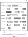
- the schedule 8 determined by the constraint optimization solver can allocate the resources 9 of automated laboratory equipment to particular tasks at particular times.
- the example automated laboratory equipment includes eight different resources. The steps belonging to different orders are illustrated by bars with different hatchings.
- resource #1 is scheduled to carry out tasks belonging to four different orders.
- resource #8 can be an incubator. At a predetermined point in time, the incubator is scheduled to perform an incubation operation 10 on a sample to be processed as part of a particular order.
- the schedule defines and order and timing of the operations of the resources 9 of the automated laboratory equipment.
- the methods of the present disclosure can include displaying the schedule 8 to a user (e.g., on a graphical user interface).
- the techniques of the present disclosure can include transforming the information in the schedule into a graphic representation (e.g., a Gantt chart as shown in FIG. 2 or FIG. 3 or a 3D animation).
- the schedule can be represented in different other forms defining a sequence of the operations.
- the schedule might be only transmitted to a controller of the automated laboratory equipment or a simulated version of it to allow for controlling the operation according to the schedule.
- no graphic representation of the information of the schedule might be generated.
- the schedule can merely include the information regarding the sequence of the operations to carry out the plurality of orders on the automated laboratory equipment in a machine-readable format.
- the schedule can be a table or list defining a series of operations of the resources of automated laboratory equipment.
- the techniques of the present disclosure can involve leaving gaps in the schedule for particular resources. This can facilitate filling in new order after arrival in an existing schedule.
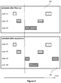
- the techniques of the present disclosure can include running the constraint optimization solver multiple times to update the schedule. For example, after a plurality of orders have been received (e.g., a predefined number of orders - this technique is also called batch processing herein) or a certain time interval has elasped, the constraint optimization solver is run a first time and generates a schedule of operations 8A for automated laboratory equipment.
- a plurality of orders e.g., a predefined number of orders - this technique is also called batch processing herein
- the constraint optimization solver is run a first time and generates a schedule of operations 8A for automated laboratory equipment.
- the automated laboratory equipment can start to process the orders according to the schedule. Then, at a later point in time, one or multiple additional orders are received. In response to receiving the additional orders, the constraint optimization solver is run a second time and generates an updated schedule of operations 8B for the automated laboratory equipment. As can be seen in FIG. 3 , in some examples, the updated schedule not only adds the operations of the newly received orders but also re-schedules operations of some of the orders that have been scheduled earlier but whose process has not been started yet. In this manner, the techniques of the present disclosure allow for scheduling both batch-wise order reception and continuously received orders.
- the schedule can be updated by re-running of the constraint optimization solver in response to one or more of these further orders.
- the schedule is continuously updated by re-running the constraint optimization solver in response to the receipt of each order.
- the constraint optimization solver is only re-run after a predetermined number of orders (e.g., between 1 and 5000 or between 6 and 2000 orders) have been received.
- the constraint optimization solver runs a first optimization run after which a subset or none of the computed schedule or the complete schedule is fixed. The remaining subset of the schedule is released. Then all, a part of or none of the corresponding orders of the released part of the schedule are included in a next optimization run, whereby the fixed subset resulting from the first optimization run is taken into the next optimization run as resource non-availability.
- a number of orders that are fixed or released again for the next batch as well as the batch-size can be constant or variable for each batch run. In some situations, e.g., due to a very early trigger, all of the orders can be newly scheduled (for instance in case of an error or when an extremely urgent order arrives before the scheduled processes have started).
- a limited number of orders e.g., ten orders
- the second run (or any further run) of the constraint optimization solver is triggered by a receipt of one or more new orders.
- other events can trigger the re-running of the constraint optimization solver to generate an updated schedule.
- the constraint optimization solver is re-run after a predetermined time has elapsed.
- a re-run can be triggered by detection of one or more external or internal conditions of the automated laboratory equipment. For instance, the operator or system may switch resources off or on, or resources can be exchanged during servicing, changing or exchanging the system. In these cases, the constraint optimization solver can be re-run to generate a new schedule with reduced, added or changed resources. In other examples, if an error occurs (e.g., a break-down of a particular resource of the automated laboratory equipment) this may automatically be signaled to the scheduler and a new schedule can be generated in response.
- an internal condition can be that one or more components of the automated laboratory equipment do not work properly.
- An external condition can include a workload or status of other automated laboratory equipment or the laboratory environment the automated laboratory equipment is located in (e.g., a number of lab personnel present at a predetermined time).
- the resource descriptions (or other parts of the model) and/or the objective functions can be changed.
- a resource description of automated laboratory equipment can be changed to account for a resource (e.g., a pipette head) which has broken down.
- an objective function can be changed and an initial objective of "maximize" throughput may be changed for "save as many orders as possible". In some cases, e.g., if an error has occurred, not all orders may be successfully processed. In this case some orders may be sacrificed (terminated) to free resources to process other, possibly more important orders.
- the constraint optimization solver is re-run after the objective function has been changed. This might happen upon user input or in response to a detection of a particular state of the automated laboratory equipment or the laboratory environment.
- the generation of the schedule of operations takes place in a simulation of the automated laboratory equipment. This case will be discussed subsequently.
- the techniques of the present disclosure can include using models including resource descriptions of the automated laboratory equipment and protocols which can be independent of the (expected or desired) schedule of operations.
- a user can modify the characteristics of the model (e.g., the resource descriptions and the protocol descriptions) and run the constraint optimization solver to simulate the behavior of automated laboratory equipment.
- new protocols for the automated equipment or laboratory workflows can be developed and tested for newly designed instruments as well as for existing instruments (e.g., after an instrument update with additional or changed protocols).
- new and/or modified automated laboratory equipment can be simulated.
- a user might add a component (e.g., an additional pipettor) to a model of existing automated laboratory equipment.
- a component e.g., an additional pipettor
- the modified model as input for the constraint optimization solver, the behavior of the laboratory equipment can be studied.
- characteristics of existing laboratory equipment can be studied by simulation. For instance, performance bottle-necks of existing laboratory equipment can be identified in schedules generated by the techniques of the present disclosure. In addition or alternatively, resource consumption (e.g., reagents or other consumable items) of an existing laboratory equipment can be estimated based on the schedules generated by the techniques of the present disclosure.
- resource consumption e.g., reagents or other consumable items
- the code is written in a form to be processed by the IBM ILOG CPLEX Optimizer.
- the IBM ILOG CPLEX Optimizer solves integer programming problems, large linear programming problems using either primal or dual variants of the simplex method or the barrier interior point method, convex and non-convex quadratic programming problems, and convex quadratically constrained problems (solved via second-order cone programming, or SOCP).
- SOCP second-order cone programming
- the techniques of the present disclosure are not limited to this particular (generic) constraint optimization solver. Rather, the model and the objective function can also be implemented to be processed by other (generic) constraint optimization solvers (as listed above).
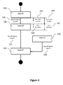
- FIG. 4 depicts an example protocol description according to the present disclosure.
- the protocol described by the protocol description can relate to any assay or other test on a sample the automated laboratory equipment can carry out.
- the protocol can relate to a preparation or manipulation of a sample.
- a protocol can relate to a cleaning, testing or maintenance operation of the automated laboratory equipment.
- the protocol description includes a description of a plurality of protocol steps 31A-31D included in the protocol, and one or more constraints 32A-32G to be observed when carrying out the protocol steps on the automated laboratory equipment.
- the protocol steps 31A-31D can include any operation the automated laboratory equipment can perform. These operations include transport of samples, reagents or consumable items (e.g., reaction vessels or instrument tips), manipulation of samples or reagents (e.g., sampling of a predetermined quantity of a reagent or sample), homogenization of fluid mixtures, incubating of fluids, measurement of a parameter of the sample, cleaning operations of reaction vessels or instrument components and disposal operations of non-renewable resources (e.g., fluids and consumables).
- reagents or consumable items e.g., reaction vessels or instrument tips
- manipulation of samples or reagents e.g., sampling of a predetermined quantity of a reagent or sample
- homogenization of fluid mixtures e.g., incubating of fluids
- measurement of a parameter of the sample e.g., cleaning operations of reaction vessels or instrument components and disposal operations of non-renewable resources (e.g., fluids and consumables).
- Step #2 31E involves pipetting 10 ⁇ l of reagent A into a reaction vessel.
- the description of the protocol steps can include other and/or further information (e.g., the duration of one or more protocol steps or an optionality flag indicating that a particular protocol step can be skipped).
- a protocol step 31A-31D can combine multiple operations of the automated laboratory equipment.
- step #1 might include adding a predetermined quantity of a sample and a reagent in a reaction vessel.
- the constraints 32A-32G included in the protocol descriptions can include one or more of a definition of the sequence of protocol steps 32E-32G, a definition of the minimum and/or maximum duration of a protocol step 32C, 32D or a definition of the minimum and/or maximum time between two subsequent protocol steps 31A-31D.
- These subsequent protocol steps can be but not necessarily have to place directly after each other. For instance, in the example of FIG. 5 step #2 must start at most one minute after step #1 has been completed.
- Protocol description for a prothrombin time assay is given in the left hand column of Table 1 below.
- the right hand column includes an explanation of various features of the protocol description.
- the protocol description includes a protocol identifier (i.e., "PT" in the example).
- the protocol description defines a sequence of the steps and various constraints to be observed.
- Table 1 «"PT", “AspireS”>, 18, 0>, Protocol "PT” requires a step named “AspireS” with execution time 1.8s (all times are expressed as multiples of 100ms). This step is obligatory (optionality flag set to zero).
- the "SpecialWash” step is optional, marked by an optionality flag which is set to "1".
- Protocol "PT” does not require a minimum delay between the end of step “AspireS” and before starting the step “DummyDispS” (value "-1").
- the maximum allowed waiting time between the steps is 120s.
- ⁇ "PT", “Dispenses”, “CuvPrepDispSR”, 2562, 2582>, The allowed time delay between the steps “DispenseS” and “CuvPrepDispSR” is at least 256.2s and at most 258.2s.
- Step "CuvLoad” has to be scheduled before “CuvToIncubator” but there are no required times for the minimal nor maximum delay the two steps (indicated by "-1").
- Resources of laboratory equipment can include, e.g., one or more of samplers and dispensers of samples and reagents (e.g., pipettors), grippers or other movers for manipulation of vessels, incubators, measurement units, cleaning stations and feeding devices for consumable items (e.g., reaction vessels, sample vessels or parts of the instrument).
- samplers and dispensers of samples and reagents e.g., pipettors
- grippers or other movers for manipulation of vessels, incubators, measurement units, cleaning stations and feeding devices for consumable items (e.g., reaction vessels, sample vessels or parts of the instrument).
- FIG. 5 An example for resource descriptions is shown in FIG. 5 .
- the example laboratory equipment includes three pipettes.
- the resource description 41-43 defines a range of volumes the respective pipettes can handle, an accuracy of the pipette, and a set of reagents the pipettes can address.
- a resource description of reagent A defines a constraint: A special wash step is required in case if another predefined reagent has been used a predetermined number of runs prior to the reagent A.
- the resource descriptions can define one or more of states in which the resource can be, processes that cause a transition from one state (level) to the next, eventually a transition time required to transition between states of the resource, requirements of states of the resource to carry out a predetermined protocol step, and incompatibilities between different states of the resource.
- the resource description includes different components.
- the resource description can include a resource definition component which defines the capacity of the respective resource, a component describing how the resource can be occupied and released by predetermined protocol steps, a resource state component which defines a dynamic behavior of the respective resource and a component defining rules to be obeyed in certain situations.
- the resource definition component defines a resource identifier and a capacity of the resource. For instance, the number of resources of a certain type available in the instrument can be defined. Resources may be separately defined (e.g., the pipettes in FIG. 5 ) as having a capacity of one, or as a joint set of resources in one unit (e.g., an incubator with a capacity of multiple cuvette positions). As shown in FIG. 5 , the resource definition component can specify additional characteristics of the respective resource.
- a code example for a resource definition component is shown in Table 2 below: Table 2 ⁇ "NeedleSample", 1>, The automated laboratory equipment includes one needle unit for the samples (“NeedleSample") and a second needle unit for reagents ("NeedleReagent"). Furthermore, there are twelve positions for cuvettes in a photometer unit and twenty positions in an incubator. ⁇ "NeedleReagent", 1>, ⁇ "PhotometerPos", 12>, ⁇ "IncubatorPos", 20>,
- the component describing how the resource can be occupied and released by predetermined protocol steps can define one or more of respective resources required for a particular protocol step, actions necessary to release a resource after it has been used in a particular protocol step and a constraint regarding a maximum number of resources that can be used.
- a code example for this component is shown in Table 3 below: Table 3 ⁇ "NeedleSample", “AspireS", 1>, Protocol step "AspireS” occupies one sample needle. There might be multiple needles of the type “Sample”. ⁇ "PhotometerPos", “CuvMoveIncub", 1>, One photometer position is used to place a cuvette in the photometer.
- Protocol step "WashNeedle” releases one sample needle. Until a wash has been carried out the needle cannot be used because it is contaminated.
- Protocol step "CuvMoveTrash” releases one photometer position as the cuvette is taken out of the photometer and disposed.
- photometerResourceUse[resCurr] ⁇ resCurr.nCapacity; Definition of the maximum allowed resource use: the current resource use shall be less or equal to the capacity.
- the resource state component can define one or more of states the respective resource can be in, a required transition time between different states, a required state for a particular protocol step and information regarding incompatibility between different states.
- a code example for this component is shown in Table 4 below: Table 4 ⁇ "TransferArm", “ReagentCassette”>, ⁇ "TransferArm", “Incubator”>, The resource “TransferArm” has two possible spatial positions: the first position being above reagent cassettes, the second position being above the incubators. ⁇ "TransferArm", “ReagentCassette”, “Incubator”, 11>, The resource “TransferArm” needs 1.1s for moving from the position "ReagentCassette” to the position "Incubator”.
- the component defining rules to be obeyed in certain situations can define different exceptions to be applied in particular situations. For instance, this component can define rules to avoid carry over (e.g., contamination of a sample or a reagent with another sample, reagent or assay) during the operation of the automated laboratory equipment.
- this component can define rules to avoid carry over (e.g., contamination of a sample or a reagent with another sample, reagent or assay) during the operation of the automated laboratory equipment.
- carry-over can be avoided by implementing one or more of: Adding one or more special cleaning steps to the schedule (e.g. with special cleaning agents) between two steps between which carry-over might occur, changing a processing order of two or more tasks between which carry-over might occur (sensitive task before contaminating task) and carrying out a predetermined number of steps (e.g. normal rinsing rather than special cleaning steps) between two tasks that cause carry-over.
- Adding one or more special cleaning steps to the schedule e.g. with special cleaning agents
- changing a processing order of two or more tasks between which carry-over might occur sensitive task before contaminating task
- a predetermined number of steps e.g. normal rinsing rather than special cleaning steps
- Table 5 A code example for this component is shown in Table 5 below: Table 5 ⁇ "CarryOver_R1", 100>, There is a carry-over type called “CarryOver_R1". Its maximum (ceiling) level is 100 units (the contamination of the resource is measured in these units). ⁇ "CAUSE", “AspireR1_CarryOver”>, ⁇ "CarryOver_R1” , 10 » Protocol step “AspireR1_CarryOver” from protocol “CAUSE” increases the level of "CarryOver R1" by ten units (until ceiling value of 100 is reached).
- Protocol step “SpecialWash_R1” from protocol “Sensitive” resets the level of “CarryOver R1" to zero.
- Protocol step “WashNeedle” from protocol “PT” reduces the level of "CarryOver_R1” by at most one unit.
- Protocol step "AspireR1" from protocol “Sensitive” requires the level of "CarryOver_R1" to be at most zero in order to be executed.
- the order list includes information regarding at least one order (e.g., a plurality of orders) to be carried out by the automated laboratory equipment, each order involving the execution of one or more protocols.
- each order can specify an assay to be performed on one sample or a batch of samples.
- each order can specify a plurality of assays to be performed on one sample or a batch of samples.
- the order list includes for each order one or more of a sample identifier to identify a sample or a batch of samples (e.g., a barcode attached to a sample container), a protocol identifier identifying one or more protocols to be applied to the sample or batch of samples and an entry time indicating a time at which the order entered the system.
- a sample identifier to identify a sample or a batch of samples (e.g., a barcode attached to a sample container)
- a protocol identifier identifying one or more protocols to be applied to the sample or batch of samples
- an entry time indicating a time at which the order entered the system.
- the order list can include for each order an expiration time indicating a time or duration until which the sample or batch of samples must be processed.
- the order list can include for each order a priority indicator indicating a priority value of a sample or batch of samples.
- the latter two pieces of information can form constraints for the solver and can be used to prioritize certain samples or batches of samples.
- the objective function defines an optimization goal for a schedule of operations for the automated laboratory equipment.
- An objective function defines an objective and the quality of a generated schedule can be judged according to the degree it reaches the objective.
- the objective function quantifies the objective so that in some cases minima or maxima of the objective function have to be found by the constraint optimization solver.
- a certain schedule might not be an absolute maximum or minimum of the objective function but nevertheless be a useful result.
- the constraint optimization solver can perform multiple runs to improve the found solution.
- the objective function can be adjusted to fulfill different optimization goals.
- the optimization goals can include minimizing one or more of a total time or duration to process one or a plurality of orders (e.g., of a batch of orders or multiple batches of orders), maximizing a throughput of automated laboratory equipment, minimizing a resource consumption (e.g., reagents, cleaning agents, or other consumable items, energy or renewable resources (instrument resources)) of the automated laboratory equipment, distributing the workload evenly over different components of the automated laboratory equipment or different automated laboratory equipment and minimizing a number of (high-priority) orders lost in case of an error occurring in the automated laboratory equipment.
- a resource consumption e.g., reagents, cleaning agents, or other consumable items, energy or renewable resources (instrument resources)
- FIG. 6A to FIG. 6C Examples of schedules generated by using different objective functions are shown in FIG. 6A to FIG. 6C .
- a batch of three or for orders 71-74 shall be scheduled.
- the total durations of the processes per order are shown.
- FIG. 6A might provide the best long term throughput even though the throughput of the schedule of FIG. 6B is higher in the short run.
- the schedule of FIG. 6C might yield to lowest processing time for each order, even though the short term throughput is lower.
- the objective function includes a weighted sum of two or more factors, wherein each factor quantifies an optimization goal.
- a weighted function could include a first term quantifying a total throughput of the automated laboratory equipment and a second term quantifying a resource consumption.
- the first term could be weighted with a larger weight factor to ensure that throughput is optimized in the first place.
- the second term could be weighted with a lower, negative weight factor to ensure that very high resource consumption is avoided.
- the overall objective function can be maximized by the constraint optimization solver to generate the schedule.
- Table 7 minimize One part of the objective function contain a term expressing the weighted penalty for the total execution time (called make span), as well as a fairness penalty term considering the total execution time of the single orders.
- make span a term expressing the weighted penalty for the total execution time (called make span)
- fairness penalty term considering the total execution time of the single orders.
- the direction of optimization is a minimization.
- the resource descriptions and protocols descriptions of the model can be linked. This might happen automatically or by user intervention.
- different parts of the model and the order list can include identifiers of different steps the automated laboratory equipment can perform (e.g., a "WashNeedle" step occurring above). In some examples, these identifiers can be used to link the respective parts of the model as part of the schedule generation process.
- FIG. 5 exemplifies such linking process.
- a protocol description 3A can define three steps. One of these steps (step #2) 31E involves pipetting a quantity of a reagent with a predefined accuracy. Now, it can be found in the resource description of the model that only one of the three pipettes 41 is capable of performing the required pipetting step and there is only one instance of the necessary reagent. Therefore, the step of the protocol is linked to the resources automatically in the course of the schedule generation or by a user. In other examples more than one resource may be applicable to carry out the protocol step. In this case, the solver will find which of the group of applicable resources is most suitable to maximize or minimize the objective function.
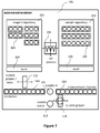
- the example automated laboratory equipment is an automated analyzer 101.
- the automated analyzer includes a reagent repository 102 including a plurality of reagents 104 (e.g., packed in standard test-specific cassettes with a plurality of reservoirs) and a sample repository 103 including a plurality of samples 105 (in, e.g., sample collection tubes).
- the automated analyzer 101 further includes a set of multiple pipettes 106 (e.g., three pipettes) which can be moved in all three spatial directions.
- the automated analyzer 101 includes multiple incubator positions 109 and multiple measurement channels 110.
- the incubation and measurement operations take place in disposable reaction vessels (called "cuvettes") which are supplied through a cuvette supply 111 and disposed in a cuvette waste 113.
- the manipulation of the cuvettes can be effected by two grippers 112, 114, one of the grippers 112 having also a mixer function via shaking the cuvette.
- the automated analyzer 101 includes one or two wash stations 107, 108 configured to wash the pipettes 106.
- a batch of sample tubes with related orders arriving at the automated analyzer can each include providing a cuvette at an measurement position 110 for measuring the cuvette quality and/or blank-measurement (a first step of the protocols), pipetting a quantity of a sample 105 into the cuvette (a second step of the protocols) and adding a predetermined reagent 104 (a third step of the protocols) after which the mixture is homogenized by the mixer-gripper Then, the cuvette is placed in the incubator 109 to incubate the sample/reagent mixture for a predetermined period of time (a fourth step of the protocols).
- the cuvettes are transferred to pipette start reagent and to place it into a measurement position 110 (a fifth step of the protocols) where a measurement takes place (a sixth and seventh steps of the protocols).
- the cuvette is disposed (a final step of the protocols).
- the relatively simple protocol described herein requires scheduling the operations of a plurality of resources of the automated analyzer. This can be done by using the techniques according to the present disclosure.
- the techniques of the present disclosure are not limited to a single automated laboratory device. Rather, a schedule for a plurality automated devices can also be generated in a similar way as described herein for a single automated laboratory device.
- the model can include resource descriptions for the resources of each of the plurality of automated laboratory devices.
- a schedule for a laboratory environment including automated laboratory equipment can also be generated in a similar way as described herein for a single automated laboratory device.
- the model can include resource descriptions for the resources of the laboratory environment and protocol descriptions describing workflows in the laboratory environment.
- the operations for generating the schedule can be carried out on each suitable computer system (e.g., including a single or multiple computers) or on a plurality of computer systems linked by a communication network.
- the computer system can be integrated in the automated laboratory equipment (e.g., as part of a controller of an automated laboratory device).
- the schedule can be generated locally at the automated laboratory equipment.
- the computer system can be arranged remotely from the automated laboratory equipment for which a schedule is generated.
- the computer system can be part of a laboratory environment and networked to the automated analyzer through a laboratory network.
- the computer system can be remote from the laboratory environment.
- the constraint optimization solver can be running on a computer system which is connected to the automated laboratory equipment or the laboratory environment including the automated laboratory equipment for which a schedule is generated through the internet.
- the constraint optimization solver can be running on a distributed computer system (e.g., a cloud-based computer system).
- a computer program including computer-executable instructions for performing the method according to the present invention in one or more of the embodiments enclosed herein when the program is executed on a computer or computer network.
- the computer program may be stored on a computer-readable data carrier.
- one, more than one or even all of method steps as disclosed herein may be performed by using a computer or a computer network, preferably by using a computer program.
- program code means in order to perform the method according to the present invention in one or more of the embodiments enclosed herein when the program is executed on a computer or computer network.
- the program code means may be stored on a computer-readable data carrier.
- a data carrier having a data structure stored thereon, which, after loading into a computer or computer network, such as into a working memory or main memory of the computer or computer network, may execute the method according to one or more of the embodiments disclosed herein.
- a computer program product with program code means stored on a machine-readable carrier, in order to perform the method according to one or more of the embodiments disclosed herein, when the program is executed on a computer or computer network.
- a computer program product refers to the program as a tradable product.
- the product may generally exist in an arbitrary format, such as in a paper format, or on a computer-readable data carrier.
- the computer program product may be distributed over a data network.
- modulated data signal which contains instructions readable by a computer system or computer network, for performing the method according to one or more of the embodiments disclosed herein.
- one or more of the method steps or even all of the method steps of the method according to one or more of the embodiments disclosed herein may be performed by using a computer or computer network.
- any of the method steps including provision and/or manipulation of data may be performed by using a computer or computer network.
- these method steps may include any of the method steps, typically except for method steps requiring manual work, such as providing the samples and/or certain aspects of performing measurements.
- a computer or computer network comprising at least one processor, wherein the processor is adapted to perform the method according to one of the embodiments described in this description.
- a storage medium wherein a data structure is stored on the storage medium and wherein the data structure is adapted to perform the method according to one of the embodiments described in this description after having been loaded into a main and/or working storage of a computer or of a computer network.
Priority Applications (4)
| Application Number | Priority Date | Filing Date | Title |
|---|---|---|---|
| EP16189852.3A EP3299794A1 (fr) | 2016-09-21 | 2016-09-21 | Programmateur automatique destiné à un équipement de laboratoire |
| US15/704,017 US20180080949A1 (en) | 2016-09-21 | 2017-09-14 | Automated scheduler for laboratory equipment |
| CN201710839929.7A CN107860931A (zh) | 2016-09-21 | 2017-09-18 | 用于实验室设备的自动排程器 |
| JP2017178711A JP2018081081A (ja) | 2016-09-21 | 2017-09-19 | 実験室機器のための自動スケジューラ |
Applications Claiming Priority (1)
| Application Number | Priority Date | Filing Date | Title |
|---|---|---|---|
| EP16189852.3A EP3299794A1 (fr) | 2016-09-21 | 2016-09-21 | Programmateur automatique destiné à un équipement de laboratoire |
Publications (1)
| Publication Number | Publication Date |
|---|---|
| EP3299794A1 true EP3299794A1 (fr) | 2018-03-28 |
Family
ID=56979459
Family Applications (1)
| Application Number | Title | Priority Date | Filing Date |
|---|---|---|---|
| EP16189852.3A Withdrawn EP3299794A1 (fr) | 2016-09-21 | 2016-09-21 | Programmateur automatique destiné à un équipement de laboratoire |
Country Status (4)
| Country | Link |
|---|---|
| US (1) | US20180080949A1 (fr) |
| EP (1) | EP3299794A1 (fr) |
| JP (1) | JP2018081081A (fr) |
| CN (1) | CN107860931A (fr) |
Cited By (5)
| Publication number | Priority date | Publication date | Assignee | Title |
|---|---|---|---|---|
| WO2020098949A1 (fr) * | 2018-11-16 | 2020-05-22 | Eppendorf Ag | Système de laboratoire muni d'appareils de laboratoire au moins partiellement en réseau et procédé de commande d'un système de laboratoire muni d'appareils de laboratoire au moins partiellement en réseau |
| US20230004909A1 (en) * | 2021-07-02 | 2023-01-05 | Strateos, Inc. | Systems and methods for processing experimental requests at remote laboratories |
| EP4246392A1 (fr) * | 2022-03-15 | 2023-09-20 | F. Hoffmann-La Roche AG | Prévision des performances futures d'un laboratoire |
| EP4307193A1 (fr) * | 2022-07-12 | 2024-01-17 | Roche Diagnostics GmbH | Procédé permettant de faire fonctionner un système de distribution des échantillons de laboratoire, système de distribution des échantillons de laboratoire et système d'automatisation de laboratoire |
| EP4244785A4 (fr) * | 2020-11-13 | 2024-05-08 | Siemens Healthcare Diagnostics Inc | Systèmes et procédés de planification de chargement efficace en matière de calcul de laboratoires de diagnostic |
Families Citing this family (33)
| Publication number | Priority date | Publication date | Assignee | Title |
|---|---|---|---|---|
| WO2014119378A1 (fr) * | 2013-01-30 | 2014-08-07 | 株式会社 日立ハイテクノロジーズ | Système de centrifugation, système de prétraitement d'échantillon et procédé de commande |
| US20180136619A1 (en) * | 2016-11-11 | 2018-05-17 | Tung Dao | Smart and Periodic Scheduling Method for Automation System |
| EP3327596A1 (fr) * | 2016-11-23 | 2018-05-30 | F. Hoffmann-La Roche AG | Résultats de mesure de supplément d'analyseurs automatisés |
| WO2018236755A1 (fr) * | 2017-06-21 | 2018-12-27 | Abbott Molecular Inc. | Systèmes d'analyse et procédés d'identification de produits consommables et de réactifs |
| US11565266B2 (en) * | 2017-08-09 | 2023-01-31 | Hitachi High-Tech Corporation | Automatic analyzer |
| TWI633504B (zh) * | 2017-11-16 | 2018-08-21 | 財團法人工業技術研究院 | 基於樹狀搜尋的排程方法與使用此方法的電子裝置 |
| CN109975568B (zh) * | 2017-12-28 | 2022-11-11 | 深圳市新产业生物医学工程股份有限公司 | 样本架调度控制方法、系统以及医学检测设备 |
| JP6959177B2 (ja) * | 2018-04-20 | 2021-11-02 | 日立グローバルライフソリューションズ株式会社 | 電気掃除機および掃除機収納台 |
| EP3557261B1 (fr) * | 2018-04-20 | 2021-12-08 | F. Hoffmann-La Roche AG | Disponibilité juste à temps de résultats de test analytique |
| US10884721B2 (en) | 2018-05-08 | 2021-01-05 | Autodesk, Inc. | Branch objects for dependent optimization problems |
| CN109030099B (zh) * | 2018-06-06 | 2021-09-24 | 迈克医疗电子有限公司 | 取液测试方法及装置 |
| CN109030095B (zh) * | 2018-06-06 | 2021-08-31 | 迈克医疗电子有限公司 | 取液测试方法及装置 |
| WO2020074555A1 (fr) * | 2018-10-11 | 2020-04-16 | Koninklijke Philips N.V. | Outil de recommandation de programme de soins à l'échelle d'une population |
| WO2020106696A1 (fr) * | 2018-11-21 | 2020-05-28 | Beckman Coulter, Inc. | Tests de planification en environnement de laboratoire |
| CN109410674A (zh) * | 2018-12-14 | 2019-03-01 | 浙江传媒学院 | 基于实验课程表动态创建在线实验室的系统 |
| US20220057418A1 (en) * | 2018-12-20 | 2022-02-24 | Leica Biosystems Melbourne Pty Ltd | Method and system for generating a schedule of activities for an automated laboratory system |
| CN109993460B (zh) * | 2019-04-17 | 2023-04-07 | 哈尔滨理工大学 | 一种存在非紧密衔接多设备工序的综合调度方法 |
| EP3757575B1 (fr) * | 2019-06-24 | 2023-06-07 | F. Hoffmann-La Roche AG | Procédé de fonctionnement d'un laboratoire analytique |
| EP4003595A4 (fr) * | 2019-07-24 | 2022-09-21 | Siemens Healthcare Diagnostics, Inc. | Systèmes et procédés de planification de chargement basés sur l'optimisation pour analyseurs de laboratoire |
| EP4004561A4 (fr) * | 2019-07-24 | 2022-10-12 | Siemens Healthcare Diagnostics, Inc. | Procédés et systèmes d'optimisation de plan de chargement de jeux de réactifs |
| WO2021026062A1 (fr) | 2019-08-05 | 2021-02-11 | Siemens Healthcare Diagnostics Inc. | Procédés et systèmes de visualisation de temps de marche |
| CN112881703B (zh) * | 2019-11-30 | 2024-04-19 | 深圳市帝迈生物技术有限公司 | 一种血液检测装置及方法、计算机存储介质 |
| CN111477313A (zh) * | 2020-03-31 | 2020-07-31 | 苏州长光华医生物医学工程有限公司 | 化学分析仪测试项目的动态排序方法、系统、存储介质 |
| CN111507523B (zh) * | 2020-04-16 | 2023-04-18 | 浙江财经大学 | 一种基于强化学习的线缆生产调度优化方法 |
| CN111680877A (zh) * | 2020-05-06 | 2020-09-18 | 杭州传化智能制造科技有限公司 | 产线调度方法、装置、计算机设备和计算机可读存储介质 |
| CN111652398B (zh) * | 2020-05-25 | 2023-07-28 | 四川长虹空调有限公司 | 智能实验室综合处理系统 |
| CN111639774B (zh) * | 2020-05-25 | 2023-07-28 | 四川长虹空调有限公司 | 实验室智能排班方法 |
| US20230004885A1 (en) * | 2021-07-02 | 2023-01-05 | Strateos, Inc. | Systems and methods for processing experimental workflows at remote laboratories |
| US20230213539A1 (en) * | 2022-01-05 | 2023-07-06 | Waters Technologies Ireland Limited | Methods, mediums, and systems for analytical method debugging |
| CN116205023B (zh) * | 2022-07-12 | 2024-03-08 | 上海奔曜科技有限公司 | 机器人智能实验室的设计方法、装置、设备和存储介质 |
| WO2024039919A1 (fr) * | 2022-08-15 | 2024-02-22 | Fluxergy Inc. | Système de test multimodal |
| CN115577997B (zh) * | 2022-12-12 | 2023-06-09 | 上海奔曜科技有限公司 | 排程控制方法、装置、设备及计算机可读存储介质 |
| CN116882691A (zh) * | 2023-07-19 | 2023-10-13 | 特维沃(上海)智能科技有限责任公司 | 实验计划的自动排程处理方法、装置、设备及可读介质 |
Citations (4)
| Publication number | Priority date | Publication date | Assignee | Title |
|---|---|---|---|---|
| EP1881329A2 (fr) * | 2006-07-20 | 2008-01-23 | Ortho-Clinical Diagnostics, Inc. | Procédé de planification d'échantillons dans un analyseur clinique combinatoire |
| US20140129172A1 (en) * | 2012-11-07 | 2014-05-08 | Beckman Coulter, Inc. | Automated sample processing system |
| WO2014110282A1 (fr) * | 2013-01-09 | 2014-07-17 | Siemens Healthcare Diagnostics Inc. | Distribution de réactif pour l'optimisation de débit |
| US20140229955A1 (en) * | 2011-09-26 | 2014-08-14 | Theranos, Inc. | Methods, systems, and devices for real time execution and optimization of concurrent test protocols on a single device |
Family Cites Families (4)
| Publication number | Priority date | Publication date | Assignee | Title |
|---|---|---|---|---|
| FR2888328B1 (fr) * | 2005-07-08 | 2013-09-20 | Horiba Abx Sas | Procede automatise de preparation d'analyse d'echantillons de sang total et dispositif automatise pour sa mise en oeuvre |
| CN103886366B (zh) * | 2014-02-21 | 2017-04-05 | 华南理工大学 | 基于粒子群算法的全自动酶免疫仪工序调度方法 |
| CN104928874B (zh) * | 2015-06-19 | 2018-10-02 | 福建省感创精密机械有限公司 | 快速自动化实验室滴液机及控制方法 |
| CN105203781A (zh) * | 2015-09-16 | 2015-12-30 | 江苏奥迪康医学科技股份有限公司 | 临床化学一体化组合多试剂条检测装置及方法 |
-
2016
- 2016-09-21 EP EP16189852.3A patent/EP3299794A1/fr not_active Withdrawn
-
2017
- 2017-09-14 US US15/704,017 patent/US20180080949A1/en not_active Abandoned
- 2017-09-18 CN CN201710839929.7A patent/CN107860931A/zh active Pending
- 2017-09-19 JP JP2017178711A patent/JP2018081081A/ja active Pending
Patent Citations (4)
| Publication number | Priority date | Publication date | Assignee | Title |
|---|---|---|---|---|
| EP1881329A2 (fr) * | 2006-07-20 | 2008-01-23 | Ortho-Clinical Diagnostics, Inc. | Procédé de planification d'échantillons dans un analyseur clinique combinatoire |
| US20140229955A1 (en) * | 2011-09-26 | 2014-08-14 | Theranos, Inc. | Methods, systems, and devices for real time execution and optimization of concurrent test protocols on a single device |
| US20140129172A1 (en) * | 2012-11-07 | 2014-05-08 | Beckman Coulter, Inc. | Automated sample processing system |
| WO2014110282A1 (fr) * | 2013-01-09 | 2014-07-17 | Siemens Healthcare Diagnostics Inc. | Distribution de réactif pour l'optimisation de débit |
Cited By (6)
| Publication number | Priority date | Publication date | Assignee | Title |
|---|---|---|---|---|
| WO2020098949A1 (fr) * | 2018-11-16 | 2020-05-22 | Eppendorf Ag | Système de laboratoire muni d'appareils de laboratoire au moins partiellement en réseau et procédé de commande d'un système de laboratoire muni d'appareils de laboratoire au moins partiellement en réseau |
| EP4244785A4 (fr) * | 2020-11-13 | 2024-05-08 | Siemens Healthcare Diagnostics Inc | Systèmes et procédés de planification de chargement efficace en matière de calcul de laboratoires de diagnostic |
| US20230004909A1 (en) * | 2021-07-02 | 2023-01-05 | Strateos, Inc. | Systems and methods for processing experimental requests at remote laboratories |
| EP4246392A1 (fr) * | 2022-03-15 | 2023-09-20 | F. Hoffmann-La Roche AG | Prévision des performances futures d'un laboratoire |
| EP4307193A1 (fr) * | 2022-07-12 | 2024-01-17 | Roche Diagnostics GmbH | Procédé permettant de faire fonctionner un système de distribution des échantillons de laboratoire, système de distribution des échantillons de laboratoire et système d'automatisation de laboratoire |
| WO2024013070A1 (fr) * | 2022-07-12 | 2024-01-18 | F. Hoffmann-La Roche Ag | Procédé de fonctionnement d'un système de distribution d'échantillon de laboratoire, système de distribution d'échantillon de laboratoire et système d'automatisation de laboratoire |
Also Published As
| Publication number | Publication date |
|---|---|
| US20180080949A1 (en) | 2018-03-22 |
| CN107860931A (zh) | 2018-03-30 |
| JP2018081081A (ja) | 2018-05-24 |
Similar Documents
| Publication | Publication Date | Title |
|---|---|---|
| US20180080949A1 (en) | Automated scheduler for laboratory equipment | |
| EP3410323B1 (fr) | Procédé de fonctionnement d'un système de laboratoire | |
| EP1881329A2 (fr) | Procédé de planification d'échantillons dans un analyseur clinique combinatoire | |
| US20140356233A1 (en) | Automatic analysis device and reagent processing method in automatic analysis device | |
| EP2804002B1 (fr) | Système automatisé de laboratoire ayant un module de routage d'échantillons commun | |
| JP6715960B2 (ja) | 生体試料検査室スクリーニングのためのシステムおよび方法 | |
| US9846170B2 (en) | Automated analyzer | |
| JP2022033983A (ja) | 分析実験室の操作方法 | |
| US8211313B2 (en) | System for processing magnetic particles | |
| US20050220671A1 (en) | Controller for automated immunoassay system | |
| CN108700602A (zh) | 自动分析装置 | |
| EP3171177A1 (fr) | Procédé et système de laboratoire permettant de distribuer des échantillons biologiques sur des microplaques | |
| JP6476003B2 (ja) | 自動分析システム | |
| JP2020160053A (ja) | 分析実験室の動作方法 | |
| US20200382599A1 (en) | Techniques for providing data packages to analytical devices | |
| EP4004561A1 (fr) | Procédés et systèmes d'optimisation de plan de chargement de jeux de réactifs | |
| EP3848937A1 (fr) | Techniques de commande d'analyseurs automatisés | |
| EP4050614A1 (fr) | Procédé et système de gestion de priorités d'échantillons | |
| WO2020044781A1 (fr) | Dispositif et méthode d'analyse automatique | |
| JP2022543145A (ja) | ウォークアウェイ時間可視化方法およびシステム | |
| CN113272653A (zh) | 自动分析装置、自动分析系统以及检体的自动分析方法 |
Legal Events
| Date | Code | Title | Description |
|---|---|---|---|
| PUAI | Public reference made under article 153(3) epc to a published international application that has entered the european phase |
Free format text: ORIGINAL CODE: 0009012 |
|
| STAA | Information on the status of an ep patent application or granted ep patent |
Free format text: STATUS: THE APPLICATION HAS BEEN PUBLISHED |
|
| AK | Designated contracting states |
Kind code of ref document: A1 Designated state(s): AL AT BE BG CH CY CZ DE DK EE ES FI FR GB GR HR HU IE IS IT LI LT LU LV MC MK MT NL NO PL PT RO RS SE SI SK SM TR |
|
| AX | Request for extension of the european patent |
Extension state: BA ME |
|
| STAA | Information on the status of an ep patent application or granted ep patent |
Free format text: STATUS: REQUEST FOR EXAMINATION WAS MADE |
|
| 17P | Request for examination filed |
Effective date: 20180919 |
|
| RBV | Designated contracting states (corrected) |
Designated state(s): AL AT BE BG CH CY CZ DE DK EE ES FI FR GB GR HR HU IE IS IT LI LT LU LV MC MK MT NL NO PL PT RO RS SE SI SK SM TR |
|
| STAA | Information on the status of an ep patent application or granted ep patent |
Free format text: STATUS: EXAMINATION IS IN PROGRESS |
|
| STAA | Information on the status of an ep patent application or granted ep patent |
Free format text: STATUS: EXAMINATION IS IN PROGRESS |
|
| 17Q | First examination report despatched |
Effective date: 20210924 |
|
| STAA | Information on the status of an ep patent application or granted ep patent |
Free format text: STATUS: THE APPLICATION IS DEEMED TO BE WITHDRAWN |
|
| 18D | Application deemed to be withdrawn |
Effective date: 20220405 |