EP3299604B1 - Systeme und verfahren für ein mobiles kraftwerk mit verbesserter mobilität und reduzierter anhängerzahl - Google Patents
Systeme und verfahren für ein mobiles kraftwerk mit verbesserter mobilität und reduzierter anhängerzahl Download PDFInfo
- Publication number
- EP3299604B1 EP3299604B1 EP17191250.4A EP17191250A EP3299604B1 EP 3299604 B1 EP3299604 B1 EP 3299604B1 EP 17191250 A EP17191250 A EP 17191250A EP 3299604 B1 EP3299604 B1 EP 3299604B1
- Authority
- EP
- European Patent Office
- Prior art keywords
- trailer
- gas turbine
- turbine engine
- components
- generator
- Prior art date
- Legal status (The legal status is an assumption and is not a legal conclusion. Google has not performed a legal analysis and makes no representation as to the accuracy of the status listed.)
- Active
Links
Images


Classifications
-
- F—MECHANICAL ENGINEERING; LIGHTING; HEATING; WEAPONS; BLASTING
- F02—COMBUSTION ENGINES; HOT-GAS OR COMBUSTION-PRODUCT ENGINE PLANTS
- F02B—INTERNAL-COMBUSTION PISTON ENGINES; COMBUSTION ENGINES IN GENERAL
- F02B63/00—Adaptations of engines for driving pumps, hand-held tools or electric generators; Portable combinations of engines with engine-driven devices
- F02B63/04—Adaptations of engines for driving pumps, hand-held tools or electric generators; Portable combinations of engines with engine-driven devices for electric generators
- F02B63/044—Adaptations of engines for driving pumps, hand-held tools or electric generators; Portable combinations of engines with engine-driven devices for electric generators the engine-generator unit being placed on a frame or in an housing
-
- F—MECHANICAL ENGINEERING; LIGHTING; HEATING; WEAPONS; BLASTING
- F02—COMBUSTION ENGINES; HOT-GAS OR COMBUSTION-PRODUCT ENGINE PLANTS
- F02C—GAS-TURBINE PLANTS; AIR INTAKES FOR JET-PROPULSION PLANTS; CONTROLLING FUEL SUPPLY IN AIR-BREATHING JET-PROPULSION PLANTS
- F02C6/00—Plural gas-turbine plants; Combinations of gas-turbine plants with other apparatus; Adaptations of gas-turbine plants for special use
-
- B—PERFORMING OPERATIONS; TRANSPORTING
- B60—VEHICLES IN GENERAL
- B60D—VEHICLE CONNECTIONS
- B60D1/00—Traction couplings; Hitches; Draw-gear; Towing devices
-
- B—PERFORMING OPERATIONS; TRANSPORTING
- B60—VEHICLES IN GENERAL
- B60P—VEHICLES ADAPTED FOR LOAD TRANSPORTATION OR TO TRANSPORT, TO CARRY, OR TO COMPRISE SPECIAL LOADS OR OBJECTS
- B60P3/00—Vehicles adapted to transport, to carry or to comprise special loads or objects
-
- B—PERFORMING OPERATIONS; TRANSPORTING
- B62—LAND VEHICLES FOR TRAVELLING OTHERWISE THAN ON RAILS
- B62D—MOTOR VEHICLES; TRAILERS
- B62D53/00—Tractor-trailer combinations; Road trains
-
- F—MECHANICAL ENGINEERING; LIGHTING; HEATING; WEAPONS; BLASTING
- F02—COMBUSTION ENGINES; HOT-GAS OR COMBUSTION-PRODUCT ENGINE PLANTS
- F02C—GAS-TURBINE PLANTS; AIR INTAKES FOR JET-PROPULSION PLANTS; CONTROLLING FUEL SUPPLY IN AIR-BREATHING JET-PROPULSION PLANTS
- F02C3/00—Gas-turbine plants characterised by the use of combustion products as the working fluid
- F02C3/04—Gas-turbine plants characterised by the use of combustion products as the working fluid having a turbine driving a compressor
-
- F—MECHANICAL ENGINEERING; LIGHTING; HEATING; WEAPONS; BLASTING
- F16—ENGINEERING ELEMENTS AND UNITS; GENERAL MEASURES FOR PRODUCING AND MAINTAINING EFFECTIVE FUNCTIONING OF MACHINES OR INSTALLATIONS; THERMAL INSULATION IN GENERAL
- F16M—FRAMES, CASINGS OR BEDS OF ENGINES, MACHINES OR APPARATUS, NOT SPECIFIC TO ENGINES, MACHINES OR APPARATUS PROVIDED FOR ELSEWHERE; STANDS; SUPPORTS
- F16M3/00—Portable or wheeled frames or beds, e.g. for emergency power-supply aggregates, compressor sets
-
- F—MECHANICAL ENGINEERING; LIGHTING; HEATING; WEAPONS; BLASTING
- F16—ENGINEERING ELEMENTS AND UNITS; GENERAL MEASURES FOR PRODUCING AND MAINTAINING EFFECTIVE FUNCTIONING OF MACHINES OR INSTALLATIONS; THERMAL INSULATION IN GENERAL
- F16M—FRAMES, CASINGS OR BEDS OF ENGINES, MACHINES OR APPARATUS, NOT SPECIFIC TO ENGINES, MACHINES OR APPARATUS PROVIDED FOR ELSEWHERE; STANDS; SUPPORTS
- F16M5/00—Engine beds, i.e. means for supporting engines or machines on foundations
-
- H—ELECTRICITY
- H02—GENERATION; CONVERSION OR DISTRIBUTION OF ELECTRIC POWER
- H02K—DYNAMO-ELECTRIC MACHINES
- H02K7/00—Arrangements for handling mechanical energy structurally associated with dynamo-electric machines, e.g. structural association with mechanical driving motors or auxiliary dynamo-electric machines
- H02K7/18—Structural association of electric generators with mechanical driving motors, e.g. with turbines
- H02K7/1807—Rotary generators
- H02K7/1823—Rotary generators structurally associated with turbines or similar engines
-
- F—MECHANICAL ENGINEERING; LIGHTING; HEATING; WEAPONS; BLASTING
- F05—INDEXING SCHEMES RELATING TO ENGINES OR PUMPS IN VARIOUS SUBCLASSES OF CLASSES F01-F04
- F05D—INDEXING SCHEME FOR ASPECTS RELATING TO NON-POSITIVE-DISPLACEMENT MACHINES OR ENGINES, GAS-TURBINES OR JET-PROPULSION PLANTS
- F05D2220/00—Application
- F05D2220/70—Application in combination with
- F05D2220/76—Application in combination with an electrical generator
Definitions
- the subject matter disclosed herein relates to gas turbine systems, and more particularly to systems and methods for transporting and installing mobile turbomachinery.
- permanent power plants are built to provide power to customers connected to a power grid.
- the permanent power plant may not be able to meet the power demand of the customers. For example, in periods of intense growth, the demand by customers may increase to surpass the amount of power the permanent power plant can generate. In some cases, the permanent plant may be shut down or undergo equipment maintenance. As further example, natural disasters such as hurricanes and earthquakes can disrupt power for a portion of the customers.
- Mobile power plants may be transported to an environment to meet power demands of customers where permanent power plants may not be able to deliver power, or may not be able to deliver power efficiently.
- mobile power plants may be delivered to a site in a partially assembled state of components, followed by on-site setup of those components. See, for example, US 2012/153634 A1 and EP 2 910 711 B 1.
- the transport and the on-site installation of the mobile power plants may take as long as a few hours to a few days.
- US 2012/0153634 discloses a mobile power plant system comprising a turbine trailer supporting a gas turbine engine and an auxiliary equipment trailer supporting an auxiliary skid communicatively and fluidly coupled to the turbine engine during installation.
- the trailers have a plurality of wheels.
- the gas turbine engine comprises support systems including a lubrication system and a start system.
- the auxiliary skid includes components disposed within the auxiliary skid and configured to regulate and/or monitor the gas turbine engine and the lubrication system, the components including an oil cooler system providing a source of lubricant utilized by the lubricant system to circulate the lubricant through the gas turbine engine.
- the auxiliary skid includes interconnects such as electrical power and/or data communication cables between the components of the auxiliary skid and the gas turbine engine as well the lubrication system.
- the auxiliary skid further includes some kind of controller within the auxiliary skid including various support wiring and/or instruments configured to support operations of each of the gas turbine engine and the lubrication system.
- the mobile power plant system further comprises a generator trailer supporting including a generator, wherein the generator trailer has a plurality of second wheels. The turbine and generator trailers are configured to align a removable coupling between the gas turbine engine and the generator.
- EP 2 832 958 discloses a mobile gas turbine power generation unit which is trailer-mounted and may operate under conditions that involve lack of protection, cold weather and/or high humidity.
- the mobile gas turbine power generation unit comprises a gas turbine system including a turbine, a combustor, and a compressor, an electrical generator driven by the gas turbine system, and a fluid injection system that includes a fluid wash system and an anti-icing system.
- the fluid wash system is configured to inject a wash fluid into the gas turbine system and the anti-icing system is configured to inject an anti-icing fluid into the gas turbine system.
- Control components for auxiliary systems are grouped together with a control component for the gas turbine engine, which is configured to control a start-up procedure of the gas turbine engine and is associated with a controller that receives and processes feedback from the gas turbine engine via sensors.
- the components of the fluid wash system may be located on separate carts that may ride with or be integrally built into the power generation unit on the trailer.
- the disclosed embodiments are directed to systems and methods for transporting components of a mobile power plant system to an installation site to meet power demands of customers where permanent power plants may not be able to deliver power.
- the mobile power plant is a trailer mounted system that is transported by ship, air, or road to the installation site. In some situations, the mobile power plant may be delivered to the installation site in a partially assembled state of components, with components mounted or disposed on one or more trailers (or other types of mobile bodies).
- the disclosed embodiments are directed to a mobile power plant system that includes a generator trailer, a turbine trailer, and a control house trailer.
- the mobile power plant system may include a transport trailer for transporting one or more components to the installation site. In these embodiments, the one or more components disposed on the transport trailer may be transferred from the transport trailer to the generator trailer and/or the turbine trailer on the installation site.
- the disclosed embodiments are directed to systems and methods for reducing a trailer count of the mobile power plant system by improving the arrangement of the partially assembled components disposed on the one or more trailers during transportation. Indeed, utilizing fewer trailers to transport the partially assembled components may help to improve ease of transportation and may help reduce the time and cost associated with transporting the mobile power plant system to the installation site. Further, improving the arrangement of the components on the trailers and/or reorganizing the partially assembled components on the one or more trailers may help to reduce the number of trailers utilized for transporting the mobile power plant system to the installation site.
- the disclosed embodiments may enable quick setup on-site for the mobile power plant system.
- the disclosed embodiments are configured for reducing a number of electrical power and data communication cables (e.g., cables) utilized to connect the turbine trailer and the control house trailer.
- the arrangement of the partially assembled components on the one or more trailers may help reduce interconnects between the one or more trailers, thereby reducing an installation time and improving a speed with which the mobile power plant system may be assembled.
- reducing the number of electrical power and data communication cables may help repeated installations (e.g., install and uninstall) of the mobile power plant system.
- the disclosed embodiments may enable quick disconnect and relocation to another installation site, thereby improving the flexibility and mobility of the mobile power plant system.
- features of the disclosed embodiments may improve the mobility of various component of the mobile power plant as they are transported to the installation site, and may provide for a quicker installation time of the mobile power plant on the installation site.
- various components of the mobile power plant system are disposed on one or more trailers (e.g., generator trailer, turbine trailer, control house trailer, transport trailer, etc.) and transported to the installation site.
- a generator trailer includes a generator that generates power for the mobile power plant system.
- a turbine trailer includes a gas turbine engine, an intake section that includes a silencer disposed within a housing, and/or an auxiliary skid.
- the auxiliary skid may be disposed at the rear of the turbine trailer.
- the auxiliary skid includes a number of components that are coupled (e.g., communicatively coupled) to a number of the components disposed on the turbine trailer (e.g., gas turbine engine).
- the auxiliary skid may be disposed at the front of the turbine trailer.
- the control house trailer may transport a control system having a controller, a ventilation system for the gas turbine engine, and an air ventilation system for the generator.
- the transport trailer may include a filter assembly, an air inlet filter assembly, and/or an exhaust stack.
- the transport trailer may include a crane that may be utilized to transfer each of these components from the transport trailer to the generator trailer and/or the turbine trailer during an installation phase of the mobile power plant system.
- the auxiliary skid disposed on the turbine trailer includes a turbine control panel, a water wash system, an engine lubrication system, and/or a start system (hydraulics start system).
- the auxiliary skid includes one or more interconnects (electrical power and data communication cables) between components of the auxiliary skid and the gas turbine engine.
- the hydraulics start system disposed within the auxiliary skid is configured to control and/or regulate a hydraulics motor of the gas turbine engine.
- the engine lubrication system and/or the water wash system is disposed within the auxiliary skid on the turbine trailer and is configured to control and/or regulate a lubricant and a water flow for the gas turbine engine, respectively.
- components disposed within the turbine control panel of the auxiliary skid include one or more features for monitoring and/or controlling an operation of the gas turbine engine.
- these components disposed within the auxiliary skid may help reduce the number of interconnects typically found between the one or more trailers, thereby reducing an installation time and improving a speed with which the mobile power plant system may be assembled.
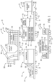
- FIG. 1 is a block diagram of an embodiment of a mobile power plant system 10 during a transportation phase according to the invention, without showing all features of the invention as claimed.
- the mobile power plant system 10 includes one or more trailers 11 that are configured to transport turbomachinery (e.g., one or more components of the mobile power plant system 10) to a desired location, such as to an installation site (e.g., on-site location) to meet power demands of customers including where permanent power plants may or may not be able to deliver power.
- the mobile power plant system 10 includes a turbine trailer 12, a generator trailer 14, and a control house trailer 16 to transport one or more components of the mobile power plant system 10 to the installation site.
- the mobile power plant system 10 may additionally include a transport trailer 18 to transport one or more additional components to the desired location.
- the components disposed on the transport trailer 18 and/or the control house trailer 16 may alternatively be transported via traditional transport techniques.
- the configuration of the mobile power plant system 10 during a transportation phase may allow for quicker installation time, lower installation cost, and greater mobility, as further described in detail below.
- the components of the mobile power plant system 10 may be assembled together during an installation phase to generate power.
- one or more of the components may be transferred between the trailers 11 during the installation phase.
- one or more of the components may be assembled together during the installation phase to generate power.
- one or more components on the transport trailer 18 may be transferred to the generator trailer 14 and/or the turbine trailer 12 during the installation phase.
- one or more components on the control house trailer 16 may be transferred to the generator trailer 14 and/or the turbine trailer 12 during the installation phase.
- the illustrated embodiment details a particular transportation phase configuration, it should be noted that other transportation phase configurations may be utilized, as further described below.
- the mobile power plant system 10 may enable power needs of industrial businesses to be met on site without constructing a traditional power plant.
- the mobile power plant system 10 may be utilized in settings such as an industrial operation or emergency site (e.g., a blackout, brownout, a natural disaster such as a flood, hurricane, or earthquakes, etc.).
- the mobile power plant system 10 includes a plurality of wheels 20 disposed beneath each of the trailers 11 (the turbine trailer 12, the generator trailer 14, the control house trailer 16, and/or the transport trailer 18) to enable efficient transportation and installation.
- the trailers 11 may include a modular design that enables faster installation on site.
- various components of the mobile power plant system 10 are mounted on one or more trailers 11 and transported (e.g., via sea, land, air) such that the mobile turbine system 10 can be deployed and commissioned quickly once it arrives to its designated location to provide power.
- the arrangement of the components of the mobile power plant system 10 between each of the one or more trailers 11 may help reduce the time and cost associated with transporting the mobile power plant system to the installation site.
- the trailers 11 may include various features that enable efficient transportation to the designated site.
- each one of the trailers 11 may include one or more steerable axles 13 that help improve mobility on land by minimizing a turning circle.
- the axles span of each one of the trailers 11 may be easily adjusted to meet the regulatory standards of a particular country.
- each one of the trailers 11 may include an air ride suspension system 15 that may be configured to assist in adjusting a quick alignment (and/or docking procedure) between one or more of the trailers 11.
- each one of the trailers 11 may include various features that enable weight (e.g., weight from components supported by the trailers 11) distribution on the trailers 11.
- the weight distribution may be determined based on country regulations, on a number and/or type of axle, on the structure of the trailer 11, on the number and/or type of components to be transported, or a combination thereof.
- the components of the mobile power plant system 10 may be arranged on the trailers 11 based on the number and weight of components to be transported and the available axles (e.g., each axle may support a different amount of weight) and/or structure (e.g., a gooseneck on the trailer 11 may support additional weight).
- the turbine trailer 12 is configured to transport a turbine (a gas turbine engine 22) to an installation site.
- the gas turbine engine 22 disposed within an enclosure 24 is mounted on the turbine trailer 12.
- an air intake section 26 having a silencer 28 disposed within a housing 30 may be mounted on the turbine trailer 12.
- An auxiliary skid 32 is disposed at a rear end 34 (e.g., opposite a head end 36) of the turbine trailer 12.
- the auxiliary skid 32 may be mounted on a rear attachment 38 of the turbine trailer 12.
- the auxiliary skid 32 may be disposed at the front end of the turbine trailer 12, and may be mounted on a front attachment 38.
- Additional support systems are disposed within the enclosure 24, and/or may be coupled or integrated within the gas turbine engine 22.
- a lubrication system 40 configured to circulate a lubricant through moving parts of the gas turbine engine 22, and a water wash system 42 configured to inject one or more fluid flows (e.g., water, steam, etc.) are disposed on the turbine trailer 12.
- the auxiliary skid 32 includes one or more quick interconnects 44 (electrical power and data communication cables) between components of the auxiliary skid 32 and the gas turbine engine 22, the lubrication system 40, and/or the water wash system 42.
- the auxiliary skid 32 includes one or more components configured to regulate and/or monitor the gas turbine engine 22 and/or the support systems (the lubrication system 40, the water wash system 42, etc.).
- support systems may be associated with the gas turbine engine 22, such as a fluid injection system configured to inject one or more fluid flows (e.g., water, steam, inert gas such as nitrogen, recirculated exhaust gas, or any combination thereof) into the gas turbine engine 22, a coolant system, a fuel system configured to supply a fuel flow, a thermal/clearance control system, or any other support system associated with the gas turbine engine 22.
- fluid injection system configured to inject one or more fluid flows (e.g., water, steam, inert gas such as nitrogen, recirculated exhaust gas, or any combination thereof) into the gas turbine engine 22, a coolant system, a fuel system configured to supply a fuel flow, a thermal/clearance control system, or any other support system associated with the gas turbine engine 22.
- fluid flows e.g., water, steam, inert gas such as nitrogen, recirculated exhaust gas, or any combination thereof
- coolant system e.g., water, steam, inert gas such as nitrogen, re
- a load 50 of the mobile power plant system 10 includes a generator 52.
- the generator 52 configured to generate power for the mobile power plant system 10 is mounted on the generator trailer 14.
- one or more additional support components such as a gas fuel filter 54, may be mounted on the generator trailer 14 during the transportation phase and/or the installation phase.
- various other components 55 e.g., switch gear, heat exchanger, etc.
- a switch gear configured to connect the generator 52 to the power grid may be mounted on the generator trailer 14.
- a heat exchanger configured to cool generator lube oil may be mounted on the generator trailer 14 during the transportation phase.
- the one or more support components mounted on the generator trailer 14 may be transferred during an installation phase of the mobile power plant system 10.
- the gas turbine engine 22 may be removably coupled to the generator 52 via a common shaft 56, and may drive the generator 52.
- the generator 52 is aligned with the gas turbine engine 22 via the generator trailer 14 and the turbine trailer 12, respectively. Further, the generator 52 may be removably coupled to the gas turbine engine 22 during a docking process of the installation phase.
- the control house trailer 16 may include one or more components configured to monitor and/or regulate the operations of the mobile power plant system 10.
- the control house trailer 16 may include a battery system, a fire suppression system (e.g., firewalls), a charging system, and/or other systems for controlling or regulating the operations of the mobile power plant system 10.
- a control system 70 including a controller 72 coupled to a processor 74 and a memory 76 may be mounted on the control house trailer 16 during the transportation phase and/or the installation phase.
- a vent system 78 associated with the gas turbine engine 22
- an air vent system 80 associated with the generator 52
- the vent system 78 may be transferred to the turbine trailer 12 and the air vent system 80 may be transferred to the generator trailer 14.
- the vent system 78 may be configured to ventilate the space surrounding the gas turbine engine 22, and the air vent system 80 may be configured to ventilate the space surrounding the generator 52.
- the vent system 78 may include a plurality of fans to enable sufficient cooling of the gas turbine engine 22, and more particularly, the enclosure 24 within which the gas turbine engine 22 is disposed within.
- the controller 72 of the control system 70 is configured to receive and process feedback from gas turbine engine 22 via the auxiliary skid 32.
- the memory 76 stores software instructions or code that is executable by the processor 74 to control various aspects of the gas turbine engine 22 and the support systems (e.g., the lubrication system 40, the water wash system 42, etc.).
- the auxiliary skid 32 includes interconnects configured to interface with the gas turbine engine 22 and support systems associated with the gas turbine engine 22 (the lubrication system 40, the water wash system 42, etc.).
- the controller 72 is configured to interface with the auxiliary skid 32 to receive and process feedback from the gas turbine engine 22 and/or the support systems associated with the gas turbine engine 22.
- the controller 72 is configured to receive and process feedback related to the gas turbine engine 22 via the auxiliary skid 32, thereby reducing a number of electrical and/or communication lines (e.g., cables) between the control house trailer 16 and the turbine trailer 12, as further described with respect to FIG. 5 .
- electrical and/or communication lines e.g., cables
- the transport trailer 18 may be configured to transport a filter assembly 82, an exhaust stack 84, and an air inlet filter assembly 86.
- the filter assembly 82 may include a first filter 88 and a second filter 90.
- the filter assembly 82 may be transferred from the transport trailer 18 to the turbine trailer 12 during the installation phase, and may be configured to couple with the air intake section 26 and the vent system 78.
- the filter assembly 82 may be configured to filter and intake the air flow into the gas turbine engine 22, as further described with respect to FIGS. 4 and 5 .
- the air inlet filter assembly 86 may include a first air inlet filter 92 and a second air inlet filter 94. As further described with respect to FIG. 4 , the air inlet filter assembly 86 may be transferred from the transport trailer 18 to the generator trailer 14 during the installation phase, and may be configured to couple with the air vent system 80. The air inlet filter assembly 86 may be configured to filter the air flow into the generator 52, as further described with respect to FIGS. 4 and 5 . In certain embodiments, the transport trailer 18 may be configured to transport the exhaust stack 84 (e.g., conduit, silencer, emissions control equipment), which may be configured to discharge an exhaust gas from the gas turbine engine 22, as further described with respect to FIG. 5 .
- the exhaust stack 84 e.g., conduit, silencer, emissions control equipment
- the transport trailer 18 may include a crane 96, which may be utilized during the installation phase to transfer one or more components from transport trailer 18 to the turbine trailer 12 and/or the generator trailer 14.
- the crane 96 may be utilized to transfer the filter assembly 82 and the exhaust stack 84 to the turbine trailer 12.
- the crane 96 may be utilized to transfer the air inlet filter assembly 86 to the generator trailer 14. It should be noted that in certain embodiments, one or more additional components of the mobile power plant system 10 may be transported to the installation site on the transport trailer 18.
- the gas fuel filter 54, the air vent system 80, and/or the vent system 78 may be mounted on the transport trailer 18 for transport to the installation site.
- one or more components mounted on the transport trailer 18 may be mounted on the control house trailer 16 for transport, and/or may be transported via alternative transportation techniques.
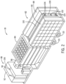
- FIG. 2 is a perspective view of an embodiment of the transport trailer 18 of FIG. 1 , during the transportation phase of the mobile power plant system 10.
- the transport trailer 18 includes the filter assembly 82 (e.g., the first filter 88 and the second filter 90), the exhaust stack 84, and the air inlet filter assembly 86 (e.g., the first air inlet filter 92 and the second air inlet filter 94).
- the transport trailer 18 may include the crane 96 configured to transfer one or more components mounted on the transport trailer 18 onto the turbine trailer 12 and/or the generator trailer 14.
- any alternative transfer mechanism may be utilized to transfer the one or more components from the transport trailer 18 to the turbine trailer 12 and/or the generator trailer 14.
- the crane 96 may be utilized to transfer the first filter 88 and the second filter 90 of the filter assembly 82 from the transport trailer 18 to the turbine trailer 12.
- the first and second filters 88, 90 may be coupled to the air intake section 26 associated with the gas turbine engine 22 and mounted on the turbine trailer 12.
- the filter assembly 82 may be disposed vertically on the transport trailer 18, such that the first and second filters 88, 90 are coupled along a centerline connection 100.
- the centerline connection 100 may include one or more attachment mechanisms 102 (e.g., bolts, fasteners, screws, etc.) that are configured to secure the first and second filters 88, 90 to each other and to the transport trailer 18.
- the first filter 88 and the second filter 90 may each include one or more support mechanisms 104 configured to engage with the centerline connection 100 via one or more attachment mechanisms 102.
- the one or more support mechanisms 104 may be utilized to couple each of the filters 88, 90 to the air intake section 26 during the installation phase.
- the first air inlet filter 92 and the second air inlet filter 94 of the air inlet assembly 86 may be disposed within a filter housing 106.
- the filter housing 106 may be configured to enclose and/or partially enclose the air inlet assembly 86, thereby securing the individual components of the air inlet assembly 86 during the transportation phase.
- an operator may uncouple one or more attachment mechanisms 104 or disengage the filter housing 106 to allow the crane 96 (or other transfer device) to transfer the filter assembly 82 and/or the air inlet assembly 86 to the generator trailer 14.
- FIG. 3 is a perspective view of an embodiment of the control house trailer 16 of FIG. 1 , during a transportation phase of the mobile power plant system 10.
- the control house trailer 16 includes the control system 70, the vent system 78, and the air vent system 80.
- the vent system 78 may be transferred from the control house trailer 16 to the turbine trailer 12, as further described with respect to FIG. 4 .
- the air vent system 80 may be transferred from the control house trailer 16 to the generator trailer 14, as further described with respect to FIG. 4 .
- control system 70 may be disposed within a control housing 110, which may be configured to secure the controller 72 (coupled to the processor 74 and the memory 76) within during transport.
- the controller 72 may interface directly with components mounted on the turbine trailer 12 (or the generator trailer 14) with one or more direct electrical power and data communication cables (e.g., cables).
- the controller 72 may be configured to interface with the auxiliary skid 32 of the turbine trailer 12.
- the controller 70 may be configured to receive and process feedback from the auxiliary skid 32, which in turn may be communicatively coupled to one or more components of the gas turbine engine 22.
- the auxiliary skid 32 disposed on the turbine trailer 12 may be configured to reduce a number of interconnects between the control house trailer 16 and the turbine trailer 12, as further described with respect to FIG. 5 .
- FIG. 4 is a block diagram of the mobile power plant system of FIG. 1 during an installation phase.
- the generator 52 mounted on the generator trailer 14 may be removably coupled with the gas turbine engine 22 mounted on the turbine trailer 12.
- the generator 52 is aligned with the gas turbine engine 22 during a docking process, and the generator trailer 14 may move in a reverse direction 120 as the turbine trailer 12 is stationary so that the generator 52 may be removably coupled with the gas turbine engine 22.
- the turbine trailer 12 may move towards the stationary generator trailer 14 and/or both trailers 12, 14 may move towards one another during the docking process.
- one or more components mounted on the transport trailer 18 and/or the control house trailer 16 may be transferred to complete the installation and commissioning of the mobile power plant system 10.
- the one or more components mounted on the transport trailer 18 and/or the control house trailer 16 may be transferred and installed prior to the docking process.
- one or more components on the transport trailer 18 and/or the control house trailer 16 may be transferred to the generator trailer 14 and/or the turbine trailer 12.
- the filter assembly 82 and the exhaust stack 84 may be transferred from the transport trailer 18 to the turbine trailer 12.
- the first filter 88 may be transferred along a reference path 122 to be coupled to a first side 124 of the air intake section 30.
- the second filter 90 may be transferred along a reference path 126 to be coupled to a second side 128 (opposite the first side 124) of the air intake section 30.
- the first and second filters 88, 90 may be fastened or secured to the air intake section 30 via the one or more attachment mechanisms 102.
- the one or more support mechanisms 104 may be utilized to secure the first and second filters 88, 90 along the first and second sides 124, 128 of the air intake section 30.
- the exhaust stack 84 may be transferred along a reference path 132 from the transport trailer 18 to the turbine trailer 12, such that it is disposed to the top surface of the enclosure 24.
- the vent system 78 may be transferred along a reference path 130 from the control house trailer 16 to the turbine trailer 12.
- the vent system 78 may be mounted above the air intake section 30 and the gas turbine engine 22, such that it is coupled to a top surface of the enclosure 24.
- the air vent system 80 may be transferred along a reference path 134 from the control house trailer 16 to the generator trailer 14.
- the air vent system 80 may be mounted above the generator 52, such that it is disposed above a top surface of the generator 52.
- the air inlet filter assembly 86 (including the first air inlet filter 92 and the second air inlet filter 94) may be transferred from the transport trailer 18 to the generator trailer 14.
- the first air inlet filter 92 may be transferred along a reference path 136 (from the transport trailer 18 to the generator trailer 14) and coupled to a first side 138 of the air vent system 78.
- the second air inlet filter 94 may be transferred along a reference path 140 (from the transport trailer 18 to the generator trailer 14) and coupled to a second side 142 of the air vent system 78.
- one or more additional components may be mounted on the turbine trailer 12 and/or the generator trailer 14, and may be transferred during the installation phase.
- the gas fuel filter 54 may be disposed on the generator trailer 14, and may be transferred along a reference path 144 and coupled to an interconnect hose 146 associated with the turbine trailer 12.
- the gas fuel filter 54 may be configured to filter a gas fuel, such as natural gas, propane, etc.
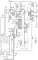
- FIG. 5 is a block diagram of the mobile power plant system 10 of FIG. 1 , depicting one or more interconnects 44 between the auxiliary skid 32 and the gas turbine engine 22, according to the invention as claimed.
- the illustrated block diagram shows the assembled mobile power plant system 10, after the transportation and installation phases.
- the arrangement of the partially assembled components on the one or more trailers 11 helps reduce a number of interconnects (electrical power and/or data communication cables 45, fluid lines 181, etc.) between the one or more trailers 11, thereby reducing an installation time and improving a speed with which the mobile power plant system 10 may be assembled.
- a partial view of the mobile power plant system 10, including the turbine trailer 12 and the generator trailer 14, after an installation phase is depicted.
- one or more interconnects communicatively couple a turbine control panel 150 disposed within the auxiliary skid 32 to one or more systems associated with the gas turbine engine 22, as further described in detail below.
- the interconnects 44 are electrical power and data communication cables 45, as well as fluid lines 181 that are configured to route a fluid (e.g., synthetic lube oil, hydraulic lube oil, water, cleaning fluid, etc.) from the auxiliary skid 32 to the gas turbine engine 22.
- a fluid e.g., synthetic lube oil, hydraulic lube oil, water, cleaning fluid, etc.
- the gas turbine engine 22 may include a gas turbine 152 coupled to the compressor 154 via the common shaft 56.
- Atmospheric air 156 may enter the filter assembly 82 to remove contaminants prior to entering the compressor 154.
- the filter assembly 82 may include filtration equipment to remove dust, sand, discharge gases, or other environmental contaminants from the air 156 prior to entering the intake section 30.
- the compressor 154 intakes oxidant (e.g., air 156) into the gas turbine engine 22 via the air intake section 30.
- the oxidant may include, but is not limited to, air 156, oxygen, oxygen-enriched air, oxygen-reduced air, or any combination thereof.
- the oxidant (e.g., air 156) may be taken in by the air intake section 30 into the gas turbine engine 22 via a suitable intake section, such as a cold air intake section, for subsequent delivery of the oxidant into the compressor 154.
- a suitable intake section such as a cold air intake section
- the intake section 30 may utilize the heat exchanger to control the temperature of the filtered air prior to introducing the air 156 to the compressor 154.
- the compressor 154 compresses the inlet air, forming pressurized air (e.g., compressed air) by rotating blades within the compressor 154.
- the pressurized air 158 enters a fuel nozzle 160 and mixes with a fuel 162 to form an air-fuel mixture.
- the gas turbine engine 22 may operate with a gas fuel or a liquid fuel.
- the fuel source may be regulated by the fuel system that may be coupled to a combustor 164.
- the fuel nozzle 158 directs the air-fuel mixture into the combustor 164.
- the combustor 164 ignites and combusts the air-fuel mixture, to form combustion products.
- the combustion products are directed to the gas turbine 152, where the combustion products expand and drive blades of the gas turbine 152 about the shaft 56.
- the gas turbine 22 may drive the load 50 via the common shaft 56.
- the load 50 may include the generator 52 (e.g., electrical generator).
- the combustion products exit the gas turbine 152 as exhaust gases 166, which then exit the mobile power plant system 10 via an exhaust stack 84.
- the exhaust gases 166 may be directed outside the enclosure 24.
- the gas turbine engine 22 may be coupled to the ventilation system 78 (e.g., the vent system 78) and the exhaust stack 84.
- the ventilation system 78 may remove some of the heat from the turbine 152 so that the turbine 152 may operate without disruption due to overheating.
- the ventilation system 78 may also enable leaked gas to be diluted and dispersed adequately to avoid accumulation of gas.
- the exhaust gases 166 may exit the gas turbine engine 22 through a diffuser into the exhaust stack 84.
- the exhaust stack 84 may be coupled to the gas turbine engine 22 by an exhaust frame.
- the exhaust stack 84 may enable high-pressure gases to exit the enclosure of the gas turbine engine 22 in embodiments where the mobile power plant system 10 is enclosed.
- the gas turbine engine 22 includes support systems, including a lubrication system 170, a hydraulics start system 172, and a water wash system 174.
- the lubrication system 170 is configured to circulate a lubricant (e.g., a synthetic lube oil through the hydraulics start system 172, a hydraulic lube oil through the turbine 152, or a combination of the synthetic lube oil and the hydraulic lube oil through both) in order to lubricate moving parts of the gas turbine engine 22.
- a lubricant e.g., a synthetic lube oil through the hydraulics start system 172, a hydraulic lube oil through the turbine 152, or a combination of the synthetic lube oil and the hydraulic lube oil through both
- four interconnects 44 e.g., four fluid lines 181 may enable fluid communication between the lubrication system 170 and the auxiliary skid 32.
- the water wash system 174 is configured to pump water (or other cleaning fluid) through the gas turbine engine 22 to clean the gas turbine engine 22.
- one interconnect 44 e.g., one fluid line 181
- the hydraulics start system 172 includes a hydraulics motor 176 associated with the gas turbine engine 22, and the hydraulics start system 172 is configured to engage the hydraulics motor 176 to start operations of the gas turbine engine 22.
- three interconnects 44 e.g., three data and/or fluid lines 181 may enable fluid communication between the hydraulics start system 172 and the auxiliary skid.
- additional support system may include a fluid injection system for injecting one or more fluid flows (e.g., water, steam, inert gas such as nitrogen, recirculated exhaust gas, cleaning fluid, oil, or any combination thereof) into the gas turbine engine 22, a coolant system, a fuel system configured to supply a fuel flow, a thermal/clearance control system, or any other support system associated with the gas turbine engine 22.
- a fluid injection system for injecting one or more fluid flows (e.g., water, steam, inert gas such as nitrogen, recirculated exhaust gas, cleaning fluid, oil, or any combination thereof) into the gas turbine engine 22, a coolant system, a fuel system configured to supply a fuel flow, a thermal/clearance control system, or any other support system associated with the gas turbine engine 22.
- the turbine control panel 150 (e.g., TCP 150) disposed within the auxiliary skid 32 is configured to directly interface with the one or more support components of the gas turbine engine 22.
- the turbine control panel 150 includes various support wiring and/or instruments configured to support operations of each of the one or more support systems of the gas turbine engine 22 (the lubrication system 170, the hydraulics start system 172, and/or the water wash system 174).
- the auxiliary skid 32 includes various support components to additionally support the operations of the support systems.
- the water wash system 174 of the gas turbine engine 22 is associated with various water wash components 180 (e.g., tank, pump, filters, motor control, etc.) disposed within the auxiliary skid 32.
- the water wash components 180 is communicatively coupled (and fluidly coupled) to the water wash system 174 of the gas turbine engine 22, to regulate a flow of water for cleaning the gas turbine engine 22.
- one or more fluid lines 181 are provided between the auxiliary skid 32 and the gas turbine engine 22 across a length 183 of the turbine trailer 12.
- the lubrication system 170 of the gas turbine engine 22 is associated with various lubrication system components 182 (e.g., tank, filters, pumps, instrumentations, motor control, etc.).
- the lubrication system components 182 include a source of the lubricant utilized by the lubrication system 170 to circulate the lubricant through the gas turbine engine 22.
- the lubrication system 170 may include a tank that is configured to hold both a synthetic lube oil (e.g., utilized within the hydraulics start system 170) and a hydraulic lube oil (e.g., utilized within the turbine 152).
- the synthetic lube oil and the hydraulic lube oil may be combined within a single tank.
- the hydraulics start system 172 of the gas turbine engine 22 includes a hydraulics motor 176 configured to start the operations of the gas turbine engine 22.
- Various support components and instrumentation e.g., hydraulics start components 184) are utilized to regulate the hydraulics motor 176 via the interconnects 44 (e.g., electrical power and/or data communication cables 45, fluid lines 181, etc.) running the length 183 of the turbine trailer 12 between the gas turbine engine 22 and the auxiliary skid 32.
- the turbine control panel 150 is associated with a controller configured to receive and process feedback from gas turbine engine 22.
- the turbine control panel 150 may be associated with the memory 76 and the processor 74.
- the memory 76 may store software instructions or code that is executable by the processor 74 to control various aspects of the gas turbine engine 22 and the support systems (e.g., the lubrication system 40, the water wash system 42, etc.).
- the turbine control panel 150 may interface (e.g., provide feedback and/or one or more data communication channels) with the control system 70 of the control house trailer 16.
- including one or more support components associated with the gas turbine engine 22 within the auxiliary skid 32 may help to reduce interconnects 44 between the one or more trailers, thereby reducing an installation time and improving a speed with which the mobile power plant system may be assembled.
- including support components associated with support systems of the gas turbine engine 22 within the auxiliary skid may help reduce a number of interconnects between the gas turbine engine 22 and the control house trailer 16.
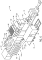
- FIG. 6 is a perspective view of the mobile power plant system 10 of FIG. 1 after an installation phase.
- the generator 52 mounted on the generator trailer 14 is coupled with the gas turbine engine 22 mounted on the turbine trailer 12.
- one or more components mounted on the transport trailer 18 and/or the control house trailer 16 may be transferred and installed to commission the mobile power plant system 10 for generating power.
- the filter assembly 82 and the exhaust stack 84 may be coupled to the gas turbine engine 22.
- the first filter 88 may be coupled to the first side 124 of the air intake section 30.
- the second filter 90 may be coupled to the second side 128 (opposite the first side 124) of the air intake section 30.
- the first and second filters 88, 90 may be fastened or secured to the air intake section 30 via the one or more attachment mechanisms 102.
- the one or more support mechanisms 104 may be utilized to secure the first and second filters 88, 90 along the first and second sides 124, 128 of the air intake section 30.
- the exhaust stack 84 may be mounted proximate to the top surface of the enclosure 24 configured to enclose the gas turbine engine 22.
- the top surface of the enclosure 24 may include a roof access that enables an operator to perform maintenance or repairs to components within the gas turbine engine 22. Further, the roof access via the top surface of the enclosure 24 may enable faster engine removal through the roof.
- the vent system 78 may be mounted above the air intake section 30 and the gas turbine engine 22, such that it is coupled to a top surface of the enclosure 24. Furthermore, in certain embodiments, the air vent system 80 may be mounted above the generator 52, such that it is disposed above a top surface of the generator 52. Additionally, in certain embodiments, the air inlet filter assembly 86 (including the first air inlet filter 92 and the second air inlet filter 94) may be coupled to the first and second sides 138, 142 of the air vent system 78.
- FIG. 7 is a perspective view of an embodiment of a silencer 200 disposed within a housing 202 of the air intake section 30 of the turbine trailer 12 of FIG. 1 , during a transportation phase of the mobile power plant system 10.
- the housing 202 may include a frame 204 configured to enclose and encase the silencer 200 during the transportation phase.
- the silencer 200 may be disposed within the air intake section 30, and may be mounted onto the turbine trailer 12 for transportation to the installation site.
- FIG. 8 is a perspective view of an embodiment of the ventilation system 78 and the exhaust stack 84 of the turbine trailer 12 of FIG. 3 , after an installation phase of the mobile power plant system 10, where the ventilation system 78 is coupled to the enclosure 24 surrounding the gas turbine engine 22 of FIG. 7 .
- Various technical effects of the invention may include improved transporting of components of a mobile power plant system 10 to an installation site via a trailer-mounted system to meet power demands of customers where permanent power plants may not be able to deliver power.
- the generator trailer 14 transports the generator 52 that generates power for the mobile power plant system 10.
- the turbine trailer 12 transports the gas turbine engine 22, the intake section 30 that includes the silencer 200 disposed within the silencer housing 202, and/or the auxiliary skid 32.
- the auxiliary skid 32 may be disposed at the rear of the turbine trailer 12 and includes a number of components that are coupled (e.g., communicatively coupled) to a number of the components associated with the gas turbine engine 22.
- control house trailer 16 may transport the control system 70 having the controller 72, the ventilation system 78 for the gas turbine engine 22, and the air ventilation system 80 for the generator 52. Further, in certain embodiments, the transport trailer 18 may transport the filter assembly 82, the air inlet filter assembly 86, and/or the exhaust stack 84.
- the disclosed embodiments are directed to systems and methods for reducing a trailer count of the mobile power plant system 10 by improving the arrangement of the partially assembled components disposed on the one or more trailers 11 during transportation.
- the arrangement of the partially assembled components on the turbine trailer 12 e.g., auxiliary skid 32
Landscapes
- Engineering & Computer Science (AREA)
- General Engineering & Computer Science (AREA)
- Mechanical Engineering (AREA)
- Chemical & Material Sciences (AREA)
- Combustion & Propulsion (AREA)
- Transportation (AREA)
- Power Engineering (AREA)
- Health & Medical Sciences (AREA)
- Public Health (AREA)
- Engine Equipment That Uses Special Cycles (AREA)
- Connection Of Motors, Electrical Generators, Mechanical Devices, And The Like (AREA)
Claims (10)
- Mobiles Kraftwerksystem (10), umfassend:einen Turbinenanhänger (12), der sowohl ein Gasturbinentriebwerk (22) als auch eine Hilfskufe (32) trägt, die sowohl während des Transports als auch nach der Installation kommunikativ und fluidisch mit dem Turbinentriebwerk (22) gekoppelt ist, wobei der Turbinenanhänger (12) eine Vielzahl von ersten Rädern (20) aufweist,wobei das Gasturbinentriebwerk (22) Trägersysteme umfasst, die ein Schmiersystem (140, 170), ein Hydraulikstartsystem (172), das einen Hydraulikmotor (176) einschließt, der konfiguriert ist, um das Gasturbinentriebwerk (22) zu starten, und ein Wasserwaschsystem (72, 174) einschließen,wobei die Hilfskufe (32) Komponenten einschließt, die konfiguriert sind, um das Gasturbinentriebwerk (22), das Schmiersystem (40, 170), das Hydraulikstartsystem (172) und das Wasserwaschsystem (42) zu regulieren und/oder zu überwachen, wobei die Komponenten Wasserwaschkomponenten (180), die mit dem Wasserwaschsystem (42, 174) des Gasturbinentriebwerks (22) kommunikativ und/oder fluidisch gekoppelt sind, um einen Fluss von Wasser zum Reinigen des Gasturbinentriebwerks (22) zu regulieren, Schmiersystemkomponenten (182), die eine Schmiermittelquelle einschließen, die durch das Schmiersystem (40, 170) des Gasturbinentriebwerks (22) verwendet wird, um das Schmiermittel durch das Gasturbinentriebwerk (22) zu zirkulieren, und Hydraulikstartkomponenten (184) einschließen, die verwendet werden, um den Hydraulikmotor (176) des Hydraulikstartsystems (172) zu regulieren;wobei die Hilfskufe (32) Verbindungen (44), die elektrische Leistungs- und Datenkommunikationskabel (45) sowie Fluidleitungen (181) zwischen den Komponenten der Hilfskufe (32) und dem Gasturbinentriebwerk (22) einschließen, das Schmiersystem (40, 170), das Waschwassersystem (42, 174) und das Hydraulikstartsystem (172) einschließt; undwobei die Hilfskufe (32) ein Turbinensteuerfeld (150) umfasst, das verschiedene Stützverdrahtung und/oder -instrumente einschließt, die konfiguriert sind, um Vorgänge jedes des Gasturbinentriebwerks (22), des Schmiersystems (40, 170), des Hydraulikstartsystems (172) und des Wasserwaschsystems (42 ,174) zu tragen, wobei das Turbinensteuerfeld (150) einer Steuerung zugeordnet ist, die konfiguriert ist, um eine Rückmeldung von dem Gasturbinentriebwerk (22) zu empfangen und zu verarbeiten; undeinen Generatoranhänger (14), der einen Generator (52) trägt, wobei der Generatoranhänger (14) eine Vielzahl von zweiten Rädern (20) aufweist und die Turbinen- und Generatoranhänger (12, 14) konfiguriert sind, um eine entfernbare Kopplung zwischen dem Gasturbinentriebwerk (22) und dem Generator (52) auszurichten.
- System (10) nach Anspruch 1, umfassend einen Steuerhausanhänger (16), der ein Steuersystem (70) trägt.
- System (10) nach Anspruch 1 oder 2, wobei die Hilfskufe (32) eine erste Kabelverbindung umfasst, die konfiguriert ist, um den Hydraulikmotor (176) zu steuern.
- System (10) nach einem der vorstehenden Ansprüche, wobei die Hilfskufe (32) einen Tank oder eine Pumpe umfasst, der/die konfiguriert ist, um ein Fluid einer Komponente eines Gasturbinentriebwerks (22) über eine Fluidleitungsverbindung (181) zuzuführen.
- System (10) nach Anspruch 4, wobei das Fluid Öl, Wasser, Dampf, Inertgas, rezirkuliertes Abgas oder eine Kombination davon umfasst.
- System (10) nach Anspruch 4, wobei das Fluid ein synthetisches Schmieröl, ein Hydraulikschmieröl oder eine Kombination davon umfasst.
- System (10) nach einem der vorstehenden Ansprüche, wobei die Hilfskufe (32) an einer vorderen/hinteren Befestigung (38) des Turbinenanhängers (12) bereitgestellt ist.
- System (10) nach einem der vorstehenden Ansprüche, ferner umfassend einen Transportanhänger (18).
- System (10) nach Anspruch 8, wobei der Transportanhänger (18) einen Kran (96) einschließt.
- System (10) nach Anspruch 8 oder 9, wobei der Transportanhänger (18) konfiguriert ist, um eine Filteranordnung (82), einen Abgaskamin (84) und eine Lufteinlassfilteranordnung (86) zu transportieren.
Applications Claiming Priority (1)
| Application Number | Priority Date | Filing Date | Title |
|---|---|---|---|
| US15/272,100 US10030579B2 (en) | 2016-09-21 | 2016-09-21 | Systems and methods for a mobile power plant with improved mobility and reduced trailer count |
Publications (2)
| Publication Number | Publication Date |
|---|---|
| EP3299604A1 EP3299604A1 (de) | 2018-03-28 |
| EP3299604B1 true EP3299604B1 (de) | 2024-05-01 |
Family
ID=60009415
Family Applications (1)
| Application Number | Title | Priority Date | Filing Date |
|---|---|---|---|
| EP17191250.4A Active EP3299604B1 (de) | 2016-09-21 | 2017-09-15 | Systeme und verfahren für ein mobiles kraftwerk mit verbesserter mobilität und reduzierter anhängerzahl |
Country Status (4)
| Country | Link |
|---|---|
| US (2) | US10030579B2 (de) |
| EP (1) | EP3299604B1 (de) |
| JP (1) | JP7109892B2 (de) |
| CN (1) | CN107859563B (de) |
Families Citing this family (100)
| Publication number | Priority date | Publication date | Assignee | Title |
|---|---|---|---|---|
| US9140110B2 (en) | 2012-10-05 | 2015-09-22 | Evolution Well Services, Llc | Mobile, modular, electrically powered system for use in fracturing underground formations using liquid petroleum gas |
| US11255173B2 (en) | 2011-04-07 | 2022-02-22 | Typhon Technology Solutions, Llc | Mobile, modular, electrically powered system for use in fracturing underground formations using liquid petroleum gas |
| US11708752B2 (en) | 2011-04-07 | 2023-07-25 | Typhon Technology Solutions (U.S.), Llc | Multiple generator mobile electric powered fracturing system |
| MX383620B (es) | 2014-12-19 | 2025-03-14 | Typhon Tech Solutions Llc | Generacion de energia electrica movil para la fracturacion hidraulica de formaciones geologicas de subsuperficie. |
| ES2584919B1 (es) * | 2016-04-20 | 2017-08-04 | Kemtecnia Tecnología Química Y Renovables, S.L. | Sistema móvil autónomo, escalable, auto desplegable, monitorizable y reprogramable de forma remota, de generación de energía eléctrica |
| US10030579B2 (en) | 2016-09-21 | 2018-07-24 | General Electric Company | Systems and methods for a mobile power plant with improved mobility and reduced trailer count |
| US10184397B2 (en) | 2016-09-21 | 2019-01-22 | General Electric Company | Systems and methods for a mobile power plant with improved mobility and reduced trailer count |
| US11624326B2 (en) | 2017-05-21 | 2023-04-11 | Bj Energy Solutions, Llc | Methods and systems for supplying fuel to gas turbine engines |
| US10704422B2 (en) * | 2017-08-29 | 2020-07-07 | On-Power, Inc. | Mobile power generation system including noise attenuation |
| US11498445B1 (en) * | 2018-01-02 | 2022-11-15 | Michael Gurin | Distributed and decoupled charging and discharging energy storage system |
| US11298994B2 (en) * | 2018-10-08 | 2022-04-12 | GM Global Technology Operations LLC | Method and apparatus for trailer load assist in a motor vehicle |
| US11085266B2 (en) * | 2018-12-20 | 2021-08-10 | Bj Services, Llc | Deployment devices and related methods for hydraulic fracturing systems |
| CN109899628A (zh) * | 2019-02-19 | 2019-06-18 | 桐城市畅润电力工程有限公司 | 一种可移动升降型应急通信装置 |
| MX2021013179A (es) | 2019-05-01 | 2021-12-10 | Typhon Tech Solutions Llc | Generacion de energia electrica movil de transporte individual. |
| US11512632B2 (en) | 2019-05-01 | 2022-11-29 | Typhon Technology Solutions (U.S.), Llc | Single-transport mobile electric power generation |
| US11560845B2 (en) | 2019-05-15 | 2023-01-24 | Bj Energy Solutions, Llc | Mobile gas turbine inlet air conditioning system and associated methods |
| US11746636B2 (en) | 2019-10-30 | 2023-09-05 | Yantai Jereh Petroleum Equipment & Technologies Co., Ltd. | Fracturing apparatus and control method thereof, fracturing system |
| US12173594B2 (en) | 2019-06-13 | 2024-12-24 | Yantai Jereh Petroleum Equipment & Technologies Co., Ltd. | Fracturing system |
| CN110118127A (zh) | 2019-06-13 | 2019-08-13 | 烟台杰瑞石油装备技术有限公司 | 一种电驱压裂设备的供电半挂车 |
| US12326074B2 (en) | 2019-06-13 | 2025-06-10 | Yantai Jereh Petroleum Equipment & Technologies Co., Ltd. | Fracturing apparatus and control method thereof, fracturing system |
| US11680474B2 (en) | 2019-06-13 | 2023-06-20 | Yantai Jereh Petroleum Equipment & Technologies Co., Ltd. | Fracturing apparatus and control method thereof, fracturing system |
| CN110159433A (zh) * | 2019-06-25 | 2019-08-23 | 烟台杰瑞石油装备技术有限公司 | 一种移动发电系统 |
| CN110284972A (zh) * | 2019-06-25 | 2019-09-27 | 烟台杰瑞石油装备技术有限公司 | 一种移动发电系统的方法 |
| US11753991B2 (en) | 2019-06-25 | 2023-09-12 | Yantai Jereh Petroleum Equipment & Technologies Co., Ltd. | Intake-exhaust transport apparatus mobile power generation system and assembling method thereof |
| CN110145399A (zh) * | 2019-06-25 | 2019-08-20 | 烟台杰瑞石油装备技术有限公司 | 一种移动式发电系统 |
| CN110374745A (zh) * | 2019-08-20 | 2019-10-25 | 烟台杰瑞石油装备技术有限公司 | 一种移动电力系统 |
| WO2021051399A1 (zh) | 2019-09-20 | 2021-03-25 | 烟台杰瑞石油装备技术有限公司 | 一种利用涡轮发动机驱动柱塞泵的水力压裂系统 |
| US12540575B2 (en) * | 2019-09-06 | 2026-02-03 | Yantai Jereh Petroleum Equipment & Technologies Co., Ltd. | Hydraulic fracturing system for driving a plunger pump with a turbine engine and noise reduction thereof |
| CA3197583A1 (en) | 2019-09-13 | 2021-03-13 | Bj Energy Solutions, Llc | Fuel, communications, and power connection systems and related methods |
| US10895202B1 (en) | 2019-09-13 | 2021-01-19 | Bj Energy Solutions, Llc | Direct drive unit removal system and associated methods |
| US12338772B2 (en) | 2019-09-13 | 2025-06-24 | Bj Energy Solutions, Llc | Systems, assemblies, and methods to enhance intake air flow to a gas turbine engine of a hydraulic fracturing unit |
| US10815764B1 (en) | 2019-09-13 | 2020-10-27 | Bj Energy Solutions, Llc | Methods and systems for operating a fleet of pumps |
| CA3092865C (en) | 2019-09-13 | 2023-07-04 | Bj Energy Solutions, Llc | Power sources and transmission networks for auxiliary equipment onboard hydraulic fracturing units and associated methods |
| US12065968B2 (en) | 2019-09-13 | 2024-08-20 | BJ Energy Solutions, Inc. | Systems and methods for hydraulic fracturing |
| US11604113B2 (en) | 2019-09-13 | 2023-03-14 | Bj Energy Solutions, Llc | Fuel, communications, and power connection systems and related methods |
| CA3092868A1 (en) | 2019-09-13 | 2021-03-13 | Bj Energy Solutions, Llc | Turbine engine exhaust duct system and methods for noise dampening and attenuation |
| US10989180B2 (en) | 2019-09-13 | 2021-04-27 | Bj Energy Solutions, Llc | Power sources and transmission networks for auxiliary equipment onboard hydraulic fracturing units and associated methods |
| CA3092829C (en) | 2019-09-13 | 2023-08-15 | Bj Energy Solutions, Llc | Methods and systems for supplying fuel to gas turbine engines |
| US11015594B2 (en) | 2019-09-13 | 2021-05-25 | Bj Energy Solutions, Llc | Systems and method for use of single mass flywheel alongside torsional vibration damper assembly for single acting reciprocating pump |
| US11015536B2 (en) | 2019-09-13 | 2021-05-25 | Bj Energy Solutions, Llc | Methods and systems for supplying fuel to gas turbine engines |
| US11002189B2 (en) | 2019-09-13 | 2021-05-11 | Bj Energy Solutions, Llc | Mobile gas turbine inlet air conditioning system and associated methods |
| CA3092863C (en) | 2019-09-13 | 2023-07-18 | Bj Energy Solutions, Llc | Fuel, communications, and power connection systems and related methods |
| CN110469405A (zh) * | 2019-09-17 | 2019-11-19 | 烟台杰瑞石油装备技术有限公司 | 一种双车载燃气轮机发电机组 |
| CN113047916A (zh) | 2021-01-11 | 2021-06-29 | 烟台杰瑞石油装备技术有限公司 | 可切换设备、井场及其控制方法、设备以及存储介质 |
| US12000253B2 (en) * | 2019-09-20 | 2024-06-04 | Yantai Jereh Petroleum Equipment & Technologies Co., Ltd. | Fracturing apparatus and fracturing system |
| US12134963B2 (en) * | 2019-09-20 | 2024-11-05 | Yantai Jereh Petroleum Equipment & Technologies Co., Ltd. | Fracturing apparatus and fracturing system |
| US11519395B2 (en) | 2019-09-20 | 2022-12-06 | Yantai Jereh Petroleum Equipment & Technologies Co., Ltd. | Turbine-driven fracturing system on semi-trailer |
| US12410695B2 (en) | 2019-09-20 | 2025-09-09 | Yantai Jereh Petroleum Equipment & Technologies Co., Ltd. | Turbine fracturing equipment |
| CN110485982A (zh) | 2019-09-20 | 2019-11-22 | 烟台杰瑞石油装备技术有限公司 | 一种涡轮压裂设备 |
| US12234712B2 (en) | 2019-09-20 | 2025-02-25 | Yantai Jereh Petroleum Equipment & Technologies Co., Ltd. | Adaptive mobile power generation system |
| CN110485983A (zh) * | 2019-09-20 | 2019-11-22 | 烟台杰瑞石油装备技术有限公司 | 一种涡轮压裂半挂车 |
| CN112901292B (zh) | 2021-03-30 | 2025-12-09 | 烟台杰瑞石油装备技术有限公司 | 排气装置及其安装方法、涡轮压裂设备 |
| US11686187B2 (en) * | 2019-09-20 | 2023-06-27 | Yantai Jereh Petroleum Equipment & Technologies Co., Ltd. | Fracturing device |
| US12163514B2 (en) | 2019-09-20 | 2024-12-10 | Yantai Jereh Petroleum Equipment & Technologies Co., Ltd. | Connecting structure, plunger pump device and generator device |
| US12264568B2 (en) | 2019-09-20 | 2025-04-01 | Yantai Jereh Petroleum Equipment & Technologies Co., Ltd. | Fracturing devices |
| US11702919B2 (en) | 2019-09-20 | 2023-07-18 | Yantai Jereh Petroleum Equipment & Technologies Co., Ltd. | Adaptive mobile power generation system |
| US12065916B2 (en) | 2019-09-20 | 2024-08-20 | Yantai Jereh Petroleum Equipment & Technologies Co., Ltd. | Hydraulic fracturing system for driving a plunger pump with a turbine engine |
| US11512683B2 (en) | 2019-10-08 | 2022-11-29 | Typhon Technology Solutions (U.S.), Llc | Chilled intake air for increased power generation |
| CN110843644A (zh) * | 2019-10-30 | 2020-02-28 | 河南平高电气股份有限公司 | 移动式发电系统及其燃气轮机发电车 |
| CN110735713A (zh) * | 2019-12-09 | 2020-01-31 | 中国船舶重工集团公司第七0三研究所 | 中大功率分体车载式燃气轮机发电机组 |
| CN110848028A (zh) * | 2019-12-17 | 2020-02-28 | 烟台杰瑞石油装备技术有限公司 | 一种用于提供移动电力的系统 |
| US12286049B2 (en) | 2020-04-28 | 2025-04-29 | Yantai Jereh Petroleum Equipment & Technologies Co., Ltd. | Vehicle-mounted gas turbine generator set |
| US11708829B2 (en) | 2020-05-12 | 2023-07-25 | Bj Energy Solutions, Llc | Cover for fluid systems and related methods |
| US10968837B1 (en) | 2020-05-14 | 2021-04-06 | Bj Energy Solutions, Llc | Systems and methods utilizing turbine compressor discharge for hydrostatic manifold purge |
| US11428165B2 (en) | 2020-05-15 | 2022-08-30 | Bj Energy Solutions, Llc | Onboard heater of auxiliary systems using exhaust gases and associated methods |
| US11208880B2 (en) | 2020-05-28 | 2021-12-28 | Bj Energy Solutions, Llc | Bi-fuel reciprocating engine to power direct drive turbine fracturing pumps onboard auxiliary systems and related methods |
| WO2021243479A1 (zh) * | 2020-06-02 | 2021-12-09 | 烟台杰瑞石油装备技术有限公司 | 一种车载式燃气轮机发电机组 |
| US10961908B1 (en) | 2020-06-05 | 2021-03-30 | Bj Energy Solutions, Llc | Systems and methods to enhance intake air flow to a gas turbine engine of a hydraulic fracturing unit |
| US11109508B1 (en) | 2020-06-05 | 2021-08-31 | Bj Energy Solutions, Llc | Enclosure assembly for enhanced cooling of direct drive unit and related methods |
| US11208953B1 (en) | 2020-06-05 | 2021-12-28 | Bj Energy Solutions, Llc | Systems and methods to enhance intake air flow to a gas turbine engine of a hydraulic fracturing unit |
| US11022526B1 (en) | 2020-06-09 | 2021-06-01 | Bj Energy Solutions, Llc | Systems and methods for monitoring a condition of a fracturing component section of a hydraulic fracturing unit |
| US11066915B1 (en) | 2020-06-09 | 2021-07-20 | Bj Energy Solutions, Llc | Methods for detection and mitigation of well screen out |
| US11111768B1 (en) | 2020-06-09 | 2021-09-07 | Bj Energy Solutions, Llc | Drive equipment and methods for mobile fracturing transportation platforms |
| US10954770B1 (en) | 2020-06-09 | 2021-03-23 | Bj Energy Solutions, Llc | Systems and methods for exchanging fracturing components of a hydraulic fracturing unit |
| US11939853B2 (en) | 2020-06-22 | 2024-03-26 | Bj Energy Solutions, Llc | Systems and methods providing a configurable staged rate increase function to operate hydraulic fracturing units |
| US12472838B1 (en) * | 2020-06-22 | 2025-11-18 | Michael Gurin | Distributed and decoupled charging and discharging energy storage system |
| US11028677B1 (en) | 2020-06-22 | 2021-06-08 | Bj Energy Solutions, Llc | Stage profiles for operations of hydraulic systems and associated methods |
| US11125066B1 (en) | 2020-06-22 | 2021-09-21 | Bj Energy Solutions, Llc | Systems and methods to operate a dual-shaft gas turbine engine for hydraulic fracturing |
| US11933153B2 (en) | 2020-06-22 | 2024-03-19 | Bj Energy Solutions, Llc | Systems and methods to operate hydraulic fracturing units using automatic flow rate and/or pressure control |
| US11473413B2 (en) | 2020-06-23 | 2022-10-18 | Bj Energy Solutions, Llc | Systems and methods to autonomously operate hydraulic fracturing units |
| US11466680B2 (en) | 2020-06-23 | 2022-10-11 | Bj Energy Solutions, Llc | Systems and methods of utilization of a hydraulic fracturing unit profile to operate hydraulic fracturing units |
| US11220895B1 (en) | 2020-06-24 | 2022-01-11 | Bj Energy Solutions, Llc | Automated diagnostics of electronic instrumentation in a system for fracturing a well and associated methods |
| US11149533B1 (en) | 2020-06-24 | 2021-10-19 | Bj Energy Solutions, Llc | Systems to monitor, detect, and/or intervene relative to cavitation and pulsation events during a hydraulic fracturing operation |
| US11193361B1 (en) | 2020-07-17 | 2021-12-07 | Bj Energy Solutions, Llc | Methods, systems, and devices to enhance fracturing fluid delivery to subsurface formations during high-pressure fracturing operations |
| CA3195134A1 (en) * | 2020-10-08 | 2022-04-14 | Typhon Technology Solutions, Llc | Single-transport mobile electric power generation |
| US11788668B1 (en) | 2020-10-26 | 2023-10-17 | Relevant Power Solutions, LLC | Mobile electric power generation trailer system and methods |
| US11598477B1 (en) | 2020-10-26 | 2023-03-07 | Relevant Power Solutions, LLC | Mobile electric power generation trailer system and methods |
| CN113315111B (zh) | 2021-04-26 | 2023-01-24 | 烟台杰瑞石油装备技术有限公司 | 一种供电方法及供电系统 |
| US11639654B2 (en) | 2021-05-24 | 2023-05-02 | Bj Energy Solutions, Llc | Hydraulic fracturing pumps to enhance flow of fracturing fluid into wellheads and related methods |
| CN113339139B (zh) | 2021-07-15 | 2024-11-29 | 烟台杰瑞石油装备技术有限公司 | 空气供应装置、燃气轮机系统及其使用方法 |
| CN215870792U (zh) | 2021-10-12 | 2022-02-18 | 烟台杰瑞石油装备技术有限公司 | 用于井场电驱设备的供电系统 |
| CA3180024A1 (en) | 2021-10-25 | 2023-04-25 | Bj Energy Solutions, Llc | Systems and methods to reduce acoustic resonance or disrupt standing wave formation in a fluid manifold of a high-pressure fracturing system |
| CN115087792B (zh) | 2022-02-16 | 2023-06-13 | 烟台杰瑞石油装备技术有限公司 | 电驱压裂系统 |
| US11668234B1 (en) * | 2022-03-23 | 2023-06-06 | Enerset Electric Ltd. | High density mobile power unit and system |
| US12104523B2 (en) * | 2022-03-23 | 2024-10-01 | Enerset Electric Ltd. | High density mobile power unit and system |
| US12172722B2 (en) * | 2022-03-23 | 2024-12-24 | Enerset Electric Ltd. | High density horsepower mobile pump system |
| US11725582B1 (en) * | 2022-04-28 | 2023-08-15 | Typhon Technology Solutions (U.S.), Llc | Mobile electric power generation system |
| WO2023233065A1 (en) * | 2022-05-31 | 2023-12-07 | Wärtsilä Finland Oy | Power generation unit and power plant |
| US11955782B1 (en) | 2022-11-01 | 2024-04-09 | Typhon Technology Solutions (U.S.), Llc | System and method for fracturing of underground formations using electric grid power |
| US12392291B1 (en) * | 2024-07-26 | 2025-08-19 | Typhon Technology Solutions (U.S.), Llc | Turbine enclosure ventilation air ducting for air handling transport |
Citations (1)
| Publication number | Priority date | Publication date | Assignee | Title |
|---|---|---|---|---|
| EP2832958A1 (de) * | 2013-07-31 | 2015-02-04 | General Electric Company | Enteisungssystem für eine Gasturbine |
Family Cites Families (64)
| Publication number | Priority date | Publication date | Assignee | Title |
|---|---|---|---|---|
| US3453443A (en) * | 1966-07-28 | 1969-07-01 | Gen Electric | Gas turbine mobile powerplant |
| US3536928A (en) * | 1968-02-09 | 1970-10-27 | Foley Machinery Co | Cooling arrangement for electric power generating plants |
| US3800966A (en) | 1971-07-12 | 1974-04-02 | G Newton | Loader crane for gooseneck trailer |
| US3791682A (en) | 1972-08-23 | 1974-02-12 | Stewart & Stevenson Serv Inc | Turbine driven electrical generator |
| US3907435A (en) | 1972-09-29 | 1975-09-23 | Laser Alignment | Light beam alignment target and method |
| DE2605941C3 (de) * | 1976-02-14 | 1980-10-30 | Mtu Motoren- Und Turbinen-Union Friedrichshafen Gmbh, 7990 Friedrichshafen | Gehäuse |
| US4136432A (en) * | 1977-01-13 | 1979-01-30 | Melley Energy Systems, Inc. | Mobile electric power generating systems |
| US4159623A (en) | 1977-11-07 | 1979-07-03 | Mcreynolds William W | Automotive step-turbine engine |
| US4159180A (en) * | 1978-02-21 | 1979-06-26 | Halliburton Company | Ground fed blender |
| US4254625A (en) | 1978-12-04 | 1981-03-10 | Saab-Scania Ab | Turbo charging systems |
| US4311395A (en) * | 1979-06-25 | 1982-01-19 | Halliburton Company | Pivoting skid blender trailer |
| DE8505239U1 (de) | 1985-02-23 | 1987-08-20 | M.A.N.- B & W Diesel GmbH, 8900 Augsburg | Schalldämpfer mit Vorleitschaufeln an der Ansaugseite des Verdichters eines Abgasturboladers |
| US4992669A (en) * | 1989-02-16 | 1991-02-12 | Parmley Daniel W | Modular energy system |
| US5517822A (en) | 1993-06-15 | 1996-05-21 | Applied Energy Systems Of Oklahoma, Inc. | Mobile congeneration apparatus including inventive valve and boiler |
| US5684578A (en) | 1994-06-23 | 1997-11-04 | Computational Systems, Inc. | Laser alignment head for use in shaft alignment |
| US6266143B1 (en) | 1997-03-20 | 2001-07-24 | Brink's Mfg. Co., Inc. | End cap incorporating laser alignment target |
| US6334746B1 (en) * | 2000-03-31 | 2002-01-01 | General Electric Company | Transport system for a power generation unit |
| US6736216B2 (en) | 2000-05-05 | 2004-05-18 | Leica Geosystems Gr, Llc | Laser-guided construction equipment |
| US6388869B1 (en) | 2000-09-19 | 2002-05-14 | Solutions Jupiter Inc. | Mobile generator unit with removable breaker box |
| US6450133B1 (en) | 2000-09-19 | 2002-09-17 | Solutions Jupiter Inc. | Partitioned container for high output mobile generator |
| US6895903B2 (en) | 2001-08-08 | 2005-05-24 | General Electric Company | Air provision systems for portable power modules |
| US7007966B2 (en) | 2001-08-08 | 2006-03-07 | General Electric Company | Air ducts for portable power modules |
| US7081682B2 (en) * | 2001-08-08 | 2006-07-25 | General Electric Company | Portable power modules and related systems |
| US6765304B2 (en) | 2001-09-26 | 2004-07-20 | General Electric Co. | Mobile power generation unit |
| US6786051B2 (en) | 2001-10-26 | 2004-09-07 | Vulcan Advanced Mobile Power Systems, L.L.C. | Trailer mounted mobile power system |
| CN2523967Y (zh) * | 2001-12-11 | 2002-12-04 | 哈尔滨东安发动机(集团)有限公司 | 车载式燃气轮机发电机组 |
| AU2003276628A1 (en) | 2002-11-27 | 2004-06-18 | Koninklijke Philips Electronics N.V. | Method and apparatus for automatic self-aligning docking of a couch with a magnetic resonance imaging scanner |
| US7221061B2 (en) * | 2002-12-02 | 2007-05-22 | Caterpillar Inc | Power generation system having an external process module |
| AU2002953528A0 (en) | 2002-12-24 | 2003-01-16 | Cowey, Steven John | An improved vehicle loading dock fender assembly |
| US6893487B2 (en) * | 2002-12-23 | 2005-05-17 | Caterpillar Inc | Power generation aftertreatment system having a particulate filter dimensioned to be interchangeable with a muffler |
| WO2005086864A2 (en) | 2004-03-09 | 2005-09-22 | Vulcan Advanced Mobile Power Systems | Power trailer structural elements for air flow, sound attenuation and fire supression |
| US7122913B2 (en) * | 2004-07-09 | 2006-10-17 | Wittmar Engineering And Construction, Inc. | Modular power generation apparatus and method |
| US7708204B2 (en) | 2005-02-07 | 2010-05-04 | Hamar Laser Instruments, Inc. | Laser alignment apparatus |
| CA2507073A1 (en) * | 2005-05-11 | 2006-11-11 | Frac Source Inc. | Transportable nitrogen pumping unit |
| CN2866855Y (zh) * | 2005-11-30 | 2007-02-07 | 中国南方航空动力机械公司 | 整体可移式燃气轮机发电机组装置 |
| GB0613929D0 (en) * | 2006-07-13 | 2006-08-23 | Rolls Royce Plc | An engine core stand arrangement and method of removal and transportation of an engine core |
| US7615876B2 (en) * | 2007-02-23 | 2009-11-10 | Marshall Michael J | Mobile power generation system and method |
| RU2342542C1 (ru) | 2007-04-04 | 2008-12-27 | Федеральное государственное унитарное предприятие "Московское машиностроительное производственное предприятие "Салют" | Установка для получения энергии |
| US8506267B2 (en) * | 2007-09-10 | 2013-08-13 | Schlumberger Technology Corporation | Pump assembly |
| US7819209B1 (en) * | 2008-05-31 | 2010-10-26 | Complete Production Services | Guided transport unit |
| CA2634861C (en) * | 2008-06-11 | 2011-01-04 | Hitman Holdings Ltd. | Combined three-in-one fracturing system |
| US7619319B1 (en) * | 2008-07-15 | 2009-11-17 | F3 & I2, Llc | Network of energy generating modules for transfer of energy outputs |
| US8294286B2 (en) * | 2008-07-15 | 2012-10-23 | F3 & I2, Llc | Network of energy generating modules for transfer of energy outputs |
| US8294285B2 (en) * | 2008-08-14 | 2012-10-23 | F3 & I2, Llc | Power packaging with railcars |
| US7608934B1 (en) * | 2008-08-14 | 2009-10-27 | F3 & I2, Llc | Power packaging with railcars |
| CN201474778U (zh) * | 2009-06-24 | 2010-05-19 | 哈尔滨东安发动机(集团)有限公司 | 集装箱式燃气轮机发电机组 |
| US8495869B2 (en) * | 2010-11-02 | 2013-07-30 | Girtz Industries Inc. | Power systems with internally integrated aftertreatment and modular features |
| US8587136B2 (en) * | 2010-12-20 | 2013-11-19 | Solar Turbines Inc. | Mobile power system |
| US9140110B2 (en) * | 2012-10-05 | 2015-09-22 | Evolution Well Services, Llc | Mobile, modular, electrically powered system for use in fracturing underground formations using liquid petroleum gas |
| ES2692897T3 (es) * | 2011-04-07 | 2018-12-05 | Evolution Well Services, Llc | Sistema energizado eléctricamente, modular, móvil para uso en formaciones subterráneas de fracturación |
| DE102011002108A1 (de) | 2011-04-15 | 2012-10-18 | Krauss-Maffei Wegmann Gmbh & Co. Kg | Krancontainer sowie Verfahren zum Betrieb eines Krancontainers |
| CN102619620A (zh) | 2012-04-10 | 2012-08-01 | 瑞昌哥尔德发电设备(无锡)制造有限公司 | 移动式高压电站 |
| US8789601B2 (en) * | 2012-11-16 | 2014-07-29 | Us Well Services Llc | System for pumping hydraulic fracturing fluid using electric pumps |
| US9410410B2 (en) * | 2012-11-16 | 2016-08-09 | Us Well Services Llc | System for pumping hydraulic fracturing fluid using electric pumps |
| US8872366B2 (en) | 2013-01-31 | 2014-10-28 | APR Energy, LLC | Scalable portable modular power plant |
| US9309842B2 (en) | 2013-02-07 | 2016-04-12 | General Electric Company | Air inlet silencer for turbomachines |
| ITFI20130110A1 (it) * | 2013-05-14 | 2014-11-15 | Nuovo Pignone Srl | Baseplate for mounting and supporting rotating machinery and system comprising said baseplate |
| US9395049B2 (en) * | 2013-07-23 | 2016-07-19 | Baker Hughes Incorporated | Apparatus and methods for delivering a high volume of fluid into an underground well bore from a mobile pumping unit |
| CN106574495B (zh) * | 2014-01-06 | 2020-12-18 | 莱姆仪器有限责任公司 | 液压压裂系统 |
| EP2910711B1 (de) | 2014-02-24 | 2020-11-04 | Caterpillar Energy Solutions GmbH | Anordnung mit einem Motor |
| US9950758B2 (en) * | 2014-09-17 | 2018-04-24 | General Electric Company | Systems and methods for a turbine trailer mechanical docking and alignment system |
| MX383620B (es) * | 2014-12-19 | 2025-03-14 | Typhon Tech Solutions Llc | Generacion de energia electrica movil para la fracturacion hidraulica de formaciones geologicas de subsuperficie. |
| US10378326B2 (en) * | 2014-12-19 | 2019-08-13 | Typhon Technology Solutions, Llc | Mobile fracturing pump transport for hydraulic fracturing of subsurface geological formations |
| US10030579B2 (en) | 2016-09-21 | 2018-07-24 | General Electric Company | Systems and methods for a mobile power plant with improved mobility and reduced trailer count |
-
2016
- 2016-09-21 US US15/272,100 patent/US10030579B2/en active Active
-
2017
- 2017-09-11 JP JP2017173640A patent/JP7109892B2/ja active Active
- 2017-09-15 EP EP17191250.4A patent/EP3299604B1/de active Active
- 2017-09-21 CN CN201710859417.7A patent/CN107859563B/zh active Active
-
2018
- 2018-07-23 US US16/043,081 patent/US10337402B2/en active Active
Patent Citations (1)
| Publication number | Priority date | Publication date | Assignee | Title |
|---|---|---|---|---|
| EP2832958A1 (de) * | 2013-07-31 | 2015-02-04 | General Electric Company | Enteisungssystem für eine Gasturbine |
Also Published As
| Publication number | Publication date |
|---|---|
| CN107859563B (zh) | 2021-12-21 |
| EP3299604A1 (de) | 2018-03-28 |
| US20180328279A1 (en) | 2018-11-15 |
| US20180080377A1 (en) | 2018-03-22 |
| CN107859563A (zh) | 2018-03-30 |
| JP2018071542A (ja) | 2018-05-10 |
| US10030579B2 (en) | 2018-07-24 |
| JP7109892B2 (ja) | 2022-08-01 |
| US10337402B2 (en) | 2019-07-02 |
Similar Documents
| Publication | Publication Date | Title |
|---|---|---|
| EP3299604B1 (de) | Systeme und verfahren für ein mobiles kraftwerk mit verbesserter mobilität und reduzierter anhängerzahl | |
| EP3299603B1 (de) | Systeme und verfahren für ein mobiles kraftwerk mit verbesserter mobilität und reduzierter anhängerzahl | |
| US6895325B1 (en) | Overspeed control system for gas turbine electric powerplant | |
| US8726609B1 (en) | Modular turbine enclosure | |
| US5517822A (en) | Mobile congeneration apparatus including inventive valve and boiler | |
| EP2532842B1 (de) | System und Verfahren zum Verpacken und Transportieren einer Gasturbine | |
| US12234712B2 (en) | Adaptive mobile power generation system | |
| US10784658B2 (en) | Mobile power generation restraint assembly | |
| CA2671005A1 (en) | Auxiliary service pack for a work vehicle | |
| US20180347469A1 (en) | Gas turbine and compressor module for on-shore lng plants | |
| US10533496B2 (en) | Compact gas turbine air inlet system | |
| US20170321700A1 (en) | Liquid injection apparatus and compressor assembly having the same | |
| RU2293219C2 (ru) | Газотурбинная энергетическая установка | |
| US20130251556A1 (en) | Power system arrangement | |
| KR102495424B1 (ko) | 가스 터빈 모듈, 이를 구비하는 가스 터빈 플랜트, 가스 터빈 모듈의 반출 방법, 및 가스 터빈 모듈의 교환 방법 | |
| US20250290449A1 (en) | Modular Power Generation Station and Configuration | |
| WO2019045689A1 (en) | MOBILE ENERGY GENERATION SYSTEM COMPRISING A CLOSED WALLED BASE STRUCTURE | |
| EP4438474A1 (de) | Flugzeugtransport für mobile energieerzeugungspakete | |
| Samson | Package Design of the RLM 1600 Gas Turbine | |
| CN114233422A (zh) | 多轴燃气蒸汽联合循环机组 | |
| ROSENCRANCE | World’s First LM5000 to LM6000 Cogeneration Plant Repowering | |
| McCarrick et al. | World’s First LM5000 to LM6000 Cogeneration Plant Repowering | |
| Breon et al. | Turbine-Compressor Train Uprated for 30% Increase in Gas Flow |
Legal Events
| Date | Code | Title | Description |
|---|---|---|---|
| PUAI | Public reference made under article 153(3) epc to a published international application that has entered the european phase |
Free format text: ORIGINAL CODE: 0009012 |
|
| STAA | Information on the status of an ep patent application or granted ep patent |
Free format text: STATUS: THE APPLICATION HAS BEEN PUBLISHED |
|
| AK | Designated contracting states |
Kind code of ref document: A1 Designated state(s): AL AT BE BG CH CY CZ DE DK EE ES FI FR GB GR HR HU IE IS IT LI LT LU LV MC MK MT NL NO PL PT RO RS SE SI SK SM TR |
|
| AX | Request for extension of the european patent |
Extension state: BA ME |
|
| STAA | Information on the status of an ep patent application or granted ep patent |
Free format text: STATUS: REQUEST FOR EXAMINATION WAS MADE |
|
| 17P | Request for examination filed |
Effective date: 20180928 |
|
| RBV | Designated contracting states (corrected) |
Designated state(s): AL AT BE BG CH CY CZ DE DK EE ES FI FR GB GR HR HU IE IS IT LI LT LU LV MC MK MT NL NO PL PT RO RS SE SI SK SM TR |
|
| STAA | Information on the status of an ep patent application or granted ep patent |
Free format text: STATUS: EXAMINATION IS IN PROGRESS |
|
| 17Q | First examination report despatched |
Effective date: 20181112 |
|
| APBK | Appeal reference recorded |
Free format text: ORIGINAL CODE: EPIDOSNREFNE |
|
| APBN | Date of receipt of notice of appeal recorded |
Free format text: ORIGINAL CODE: EPIDOSNNOA2E |
|
| APAF | Appeal reference modified |
Free format text: ORIGINAL CODE: EPIDOSCREFNE |
|
| APAV | Appeal reference deleted |
Free format text: ORIGINAL CODE: EPIDOSDREFNE |
|
| APBR | Date of receipt of statement of grounds of appeal recorded |
Free format text: ORIGINAL CODE: EPIDOSNNOA3E |
|
| APAV | Appeal reference deleted |
Free format text: ORIGINAL CODE: EPIDOSDREFNE |
|
| RAP1 | Party data changed (applicant data changed or rights of an application transferred) |
Owner name: GENERAL ELECTRIC TECHNOLOGY GMBH |
|
| APBT | Appeal procedure closed |
Free format text: ORIGINAL CODE: EPIDOSNNOA9E |
|
| GRAP | Despatch of communication of intention to grant a patent |
Free format text: ORIGINAL CODE: EPIDOSNIGR1 |
|
| STAA | Information on the status of an ep patent application or granted ep patent |
Free format text: STATUS: GRANT OF PATENT IS INTENDED |
|
| INTG | Intention to grant announced |
Effective date: 20240214 |
|
| GRAS | Grant fee paid |
Free format text: ORIGINAL CODE: EPIDOSNIGR3 |
|
| GRAA | (expected) grant |
Free format text: ORIGINAL CODE: 0009210 |
|
| STAA | Information on the status of an ep patent application or granted ep patent |
Free format text: STATUS: THE PATENT HAS BEEN GRANTED |
|
| AK | Designated contracting states |
Kind code of ref document: B1 Designated state(s): AL AT BE BG CH CY CZ DE DK EE ES FI FR GB GR HR HU IE IS IT LI LT LU LV MC MK MT NL NO PL PT RO RS SE SI SK SM TR |
|
| REG | Reference to a national code |
Ref country code: GB Ref legal event code: FG4D |
|
| REG | Reference to a national code |
Ref country code: CH Ref legal event code: EP |
|
| REG | Reference to a national code |
Ref country code: IE Ref legal event code: FG4D |
|
| REG | Reference to a national code |
Ref country code: DE Ref legal event code: R096 Ref document number: 602017081485 Country of ref document: DE |
|
| REG | Reference to a national code |
Ref country code: LT Ref legal event code: MG9D |
|
| REG | Reference to a national code |
Ref country code: NL Ref legal event code: MP Effective date: 20240501 |
|
| PG25 | Lapsed in a contracting state [announced via postgrant information from national office to epo] |
Ref country code: IS Free format text: LAPSE BECAUSE OF FAILURE TO SUBMIT A TRANSLATION OF THE DESCRIPTION OR TO PAY THE FEE WITHIN THE PRESCRIBED TIME-LIMIT Effective date: 20240901 |
|
| PG25 | Lapsed in a contracting state [announced via postgrant information from national office to epo] |
Ref country code: BG Free format text: LAPSE BECAUSE OF FAILURE TO SUBMIT A TRANSLATION OF THE DESCRIPTION OR TO PAY THE FEE WITHIN THE PRESCRIBED TIME-LIMIT Effective date: 20240501 |
|
| PG25 | Lapsed in a contracting state [announced via postgrant information from national office to epo] |
Ref country code: FI Free format text: LAPSE BECAUSE OF FAILURE TO SUBMIT A TRANSLATION OF THE DESCRIPTION OR TO PAY THE FEE WITHIN THE PRESCRIBED TIME-LIMIT Effective date: 20240501 Ref country code: HR Free format text: LAPSE BECAUSE OF FAILURE TO SUBMIT A TRANSLATION OF THE DESCRIPTION OR TO PAY THE FEE WITHIN THE PRESCRIBED TIME-LIMIT Effective date: 20240501 |
|
| PG25 | Lapsed in a contracting state [announced via postgrant information from national office to epo] |
Ref country code: GR Free format text: LAPSE BECAUSE OF FAILURE TO SUBMIT A TRANSLATION OF THE DESCRIPTION OR TO PAY THE FEE WITHIN THE PRESCRIBED TIME-LIMIT Effective date: 20240802 |
|
| PG25 | Lapsed in a contracting state [announced via postgrant information from national office to epo] |
Ref country code: PT Free format text: LAPSE BECAUSE OF FAILURE TO SUBMIT A TRANSLATION OF THE DESCRIPTION OR TO PAY THE FEE WITHIN THE PRESCRIBED TIME-LIMIT Effective date: 20240902 |
|
| REG | Reference to a national code |
Ref country code: AT Ref legal event code: MK05 Ref document number: 1682611 Country of ref document: AT Kind code of ref document: T Effective date: 20240501 |
|
| PG25 | Lapsed in a contracting state [announced via postgrant information from national office to epo] |
Ref country code: NL Free format text: LAPSE BECAUSE OF FAILURE TO SUBMIT A TRANSLATION OF THE DESCRIPTION OR TO PAY THE FEE WITHIN THE PRESCRIBED TIME-LIMIT Effective date: 20240501 |
|
| PG25 | Lapsed in a contracting state [announced via postgrant information from national office to epo] |
Ref country code: ES Free format text: LAPSE BECAUSE OF FAILURE TO SUBMIT A TRANSLATION OF THE DESCRIPTION OR TO PAY THE FEE WITHIN THE PRESCRIBED TIME-LIMIT Effective date: 20240501 |
|
| PG25 | Lapsed in a contracting state [announced via postgrant information from national office to epo] |
Ref country code: AT Free format text: LAPSE BECAUSE OF FAILURE TO SUBMIT A TRANSLATION OF THE DESCRIPTION OR TO PAY THE FEE WITHIN THE PRESCRIBED TIME-LIMIT Effective date: 20240501 |
|
| PG25 | Lapsed in a contracting state [announced via postgrant information from national office to epo] |
Ref country code: PL Free format text: LAPSE BECAUSE OF FAILURE TO SUBMIT A TRANSLATION OF THE DESCRIPTION OR TO PAY THE FEE WITHIN THE PRESCRIBED TIME-LIMIT Effective date: 20240501 |
|
| PG25 | Lapsed in a contracting state [announced via postgrant information from national office to epo] |
Ref country code: LV Free format text: LAPSE BECAUSE OF FAILURE TO SUBMIT A TRANSLATION OF THE DESCRIPTION OR TO PAY THE FEE WITHIN THE PRESCRIBED TIME-LIMIT Effective date: 20240501 |
|
| PG25 | Lapsed in a contracting state [announced via postgrant information from national office to epo] |
Ref country code: PT Free format text: LAPSE BECAUSE OF FAILURE TO SUBMIT A TRANSLATION OF THE DESCRIPTION OR TO PAY THE FEE WITHIN THE PRESCRIBED TIME-LIMIT Effective date: 20240902 Ref country code: PL Free format text: LAPSE BECAUSE OF FAILURE TO SUBMIT A TRANSLATION OF THE DESCRIPTION OR TO PAY THE FEE WITHIN THE PRESCRIBED TIME-LIMIT Effective date: 20240501 Ref country code: NO Free format text: LAPSE BECAUSE OF FAILURE TO SUBMIT A TRANSLATION OF THE DESCRIPTION OR TO PAY THE FEE WITHIN THE PRESCRIBED TIME-LIMIT Effective date: 20240801 Ref country code: NL Free format text: LAPSE BECAUSE OF FAILURE TO SUBMIT A TRANSLATION OF THE DESCRIPTION OR TO PAY THE FEE WITHIN THE PRESCRIBED TIME-LIMIT Effective date: 20240501 Ref country code: LV Free format text: LAPSE BECAUSE OF FAILURE TO SUBMIT A TRANSLATION OF THE DESCRIPTION OR TO PAY THE FEE WITHIN THE PRESCRIBED TIME-LIMIT Effective date: 20240501 Ref country code: IS Free format text: LAPSE BECAUSE OF FAILURE TO SUBMIT A TRANSLATION OF THE DESCRIPTION OR TO PAY THE FEE WITHIN THE PRESCRIBED TIME-LIMIT Effective date: 20240901 Ref country code: HR Free format text: LAPSE BECAUSE OF FAILURE TO SUBMIT A TRANSLATION OF THE DESCRIPTION OR TO PAY THE FEE WITHIN THE PRESCRIBED TIME-LIMIT Effective date: 20240501 Ref country code: GR Free format text: LAPSE BECAUSE OF FAILURE TO SUBMIT A TRANSLATION OF THE DESCRIPTION OR TO PAY THE FEE WITHIN THE PRESCRIBED TIME-LIMIT Effective date: 20240802 Ref country code: FI Free format text: LAPSE BECAUSE OF FAILURE TO SUBMIT A TRANSLATION OF THE DESCRIPTION OR TO PAY THE FEE WITHIN THE PRESCRIBED TIME-LIMIT Effective date: 20240501 Ref country code: ES Free format text: LAPSE BECAUSE OF FAILURE TO SUBMIT A TRANSLATION OF THE DESCRIPTION OR TO PAY THE FEE WITHIN THE PRESCRIBED TIME-LIMIT Effective date: 20240501 Ref country code: BG Free format text: LAPSE BECAUSE OF FAILURE TO SUBMIT A TRANSLATION OF THE DESCRIPTION OR TO PAY THE FEE WITHIN THE PRESCRIBED TIME-LIMIT Effective date: 20240501 Ref country code: AT Free format text: LAPSE BECAUSE OF FAILURE TO SUBMIT A TRANSLATION OF THE DESCRIPTION OR TO PAY THE FEE WITHIN THE PRESCRIBED TIME-LIMIT Effective date: 20240501 Ref country code: RS Free format text: LAPSE BECAUSE OF FAILURE TO SUBMIT A TRANSLATION OF THE DESCRIPTION OR TO PAY THE FEE WITHIN THE PRESCRIBED TIME-LIMIT Effective date: 20240801 |
|
| PG25 | Lapsed in a contracting state [announced via postgrant information from national office to epo] |
Ref country code: DK Free format text: LAPSE BECAUSE OF FAILURE TO SUBMIT A TRANSLATION OF THE DESCRIPTION OR TO PAY THE FEE WITHIN THE PRESCRIBED TIME-LIMIT Effective date: 20240501 |
|
| PG25 | Lapsed in a contracting state [announced via postgrant information from national office to epo] |
Ref country code: EE Free format text: LAPSE BECAUSE OF FAILURE TO SUBMIT A TRANSLATION OF THE DESCRIPTION OR TO PAY THE FEE WITHIN THE PRESCRIBED TIME-LIMIT Effective date: 20240501 |
|
| PG25 | Lapsed in a contracting state [announced via postgrant information from national office to epo] |
Ref country code: CZ Free format text: LAPSE BECAUSE OF FAILURE TO SUBMIT A TRANSLATION OF THE DESCRIPTION OR TO PAY THE FEE WITHIN THE PRESCRIBED TIME-LIMIT Effective date: 20240501 |
|
| PG25 | Lapsed in a contracting state [announced via postgrant information from national office to epo] |
Ref country code: RO Free format text: LAPSE BECAUSE OF FAILURE TO SUBMIT A TRANSLATION OF THE DESCRIPTION OR TO PAY THE FEE WITHIN THE PRESCRIBED TIME-LIMIT Effective date: 20240501 Ref country code: SK Free format text: LAPSE BECAUSE OF FAILURE TO SUBMIT A TRANSLATION OF THE DESCRIPTION OR TO PAY THE FEE WITHIN THE PRESCRIBED TIME-LIMIT Effective date: 20240501 |
|
| PG25 | Lapsed in a contracting state [announced via postgrant information from national office to epo] |
Ref country code: SM Free format text: LAPSE BECAUSE OF FAILURE TO SUBMIT A TRANSLATION OF THE DESCRIPTION OR TO PAY THE FEE WITHIN THE PRESCRIBED TIME-LIMIT Effective date: 20240501 |
|
| PG25 | Lapsed in a contracting state [announced via postgrant information from national office to epo] |
Ref country code: SM Free format text: LAPSE BECAUSE OF FAILURE TO SUBMIT A TRANSLATION OF THE DESCRIPTION OR TO PAY THE FEE WITHIN THE PRESCRIBED TIME-LIMIT Effective date: 20240501 Ref country code: SK Free format text: LAPSE BECAUSE OF FAILURE TO SUBMIT A TRANSLATION OF THE DESCRIPTION OR TO PAY THE FEE WITHIN THE PRESCRIBED TIME-LIMIT Effective date: 20240501 Ref country code: RO Free format text: LAPSE BECAUSE OF FAILURE TO SUBMIT A TRANSLATION OF THE DESCRIPTION OR TO PAY THE FEE WITHIN THE PRESCRIBED TIME-LIMIT Effective date: 20240501 Ref country code: EE Free format text: LAPSE BECAUSE OF FAILURE TO SUBMIT A TRANSLATION OF THE DESCRIPTION OR TO PAY THE FEE WITHIN THE PRESCRIBED TIME-LIMIT Effective date: 20240501 Ref country code: DK Free format text: LAPSE BECAUSE OF FAILURE TO SUBMIT A TRANSLATION OF THE DESCRIPTION OR TO PAY THE FEE WITHIN THE PRESCRIBED TIME-LIMIT Effective date: 20240501 Ref country code: CZ Free format text: LAPSE BECAUSE OF FAILURE TO SUBMIT A TRANSLATION OF THE DESCRIPTION OR TO PAY THE FEE WITHIN THE PRESCRIBED TIME-LIMIT Effective date: 20240501 |
|
| REG | Reference to a national code |
Ref country code: DE Ref legal event code: R097 Ref document number: 602017081485 Country of ref document: DE |
|
| PLBE | No opposition filed within time limit |
Free format text: ORIGINAL CODE: 0009261 |
|
| STAA | Information on the status of an ep patent application or granted ep patent |
Free format text: STATUS: NO OPPOSITION FILED WITHIN TIME LIMIT |
|
| 26N | No opposition filed |
Effective date: 20250204 |
|
| PG25 | Lapsed in a contracting state [announced via postgrant information from national office to epo] |
Ref country code: SI Free format text: LAPSE BECAUSE OF FAILURE TO SUBMIT A TRANSLATION OF THE DESCRIPTION OR TO PAY THE FEE WITHIN THE PRESCRIBED TIME-LIMIT Effective date: 20240501 Ref country code: MC Free format text: LAPSE BECAUSE OF FAILURE TO SUBMIT A TRANSLATION OF THE DESCRIPTION OR TO PAY THE FEE WITHIN THE PRESCRIBED TIME-LIMIT Effective date: 20240501 |
|
| PG25 | Lapsed in a contracting state [announced via postgrant information from national office to epo] |
Ref country code: LU Free format text: LAPSE BECAUSE OF NON-PAYMENT OF DUE FEES Effective date: 20240915 |
|
| REG | Reference to a national code |
Ref country code: BE Ref legal event code: MM Effective date: 20240930 |
|
| PG25 | Lapsed in a contracting state [announced via postgrant information from national office to epo] |
Ref country code: BE Free format text: LAPSE BECAUSE OF NON-PAYMENT OF DUE FEES Effective date: 20240930 |
|
| PG25 | Lapsed in a contracting state [announced via postgrant information from national office to epo] |
Ref country code: IE Free format text: LAPSE BECAUSE OF NON-PAYMENT OF DUE FEES Effective date: 20240915 |
|
| PG25 | Lapsed in a contracting state [announced via postgrant information from national office to epo] |
Ref country code: SE Free format text: LAPSE BECAUSE OF FAILURE TO SUBMIT A TRANSLATION OF THE DESCRIPTION OR TO PAY THE FEE WITHIN THE PRESCRIBED TIME-LIMIT Effective date: 20240501 |
|
| REG | Reference to a national code |
Ref country code: CH Ref legal event code: U11 Free format text: ST27 STATUS EVENT CODE: U-0-0-U10-U11 (AS PROVIDED BY THE NATIONAL OFFICE) Effective date: 20251001 |
|
| PGFP | Annual fee paid to national office [announced via postgrant information from national office to epo] |
Ref country code: DE Payment date: 20250820 Year of fee payment: 9 |
|
| PGFP | Annual fee paid to national office [announced via postgrant information from national office to epo] |
Ref country code: IT Payment date: 20250820 Year of fee payment: 9 |
|
| PGFP | Annual fee paid to national office [announced via postgrant information from national office to epo] |
Ref country code: GB Payment date: 20250820 Year of fee payment: 9 |
|
| PGFP | Annual fee paid to national office [announced via postgrant information from national office to epo] |
Ref country code: FR Payment date: 20250820 Year of fee payment: 9 |
|
| PGFP | Annual fee paid to national office [announced via postgrant information from national office to epo] |
Ref country code: CH Payment date: 20251001 Year of fee payment: 9 |
|
| PG25 | Lapsed in a contracting state [announced via postgrant information from national office to epo] |
Ref country code: CY Free format text: LAPSE BECAUSE OF FAILURE TO SUBMIT A TRANSLATION OF THE DESCRIPTION OR TO PAY THE FEE WITHIN THE PRESCRIBED TIME-LIMIT; INVALID AB INITIO Effective date: 20170915 |
|
| PG25 | Lapsed in a contracting state [announced via postgrant information from national office to epo] |
Ref country code: HU Free format text: LAPSE BECAUSE OF FAILURE TO SUBMIT A TRANSLATION OF THE DESCRIPTION OR TO PAY THE FEE WITHIN THE PRESCRIBED TIME-LIMIT; INVALID AB INITIO Effective date: 20170915 |