EP3299222A1 - Verbesserte tülleneinknüpfgeometrie zur leitungsabstützung - Google Patents
Verbesserte tülleneinknüpfgeometrie zur leitungsabstützung Download PDFInfo
- Publication number
- EP3299222A1 EP3299222A1 EP17192287.5A EP17192287A EP3299222A1 EP 3299222 A1 EP3299222 A1 EP 3299222A1 EP 17192287 A EP17192287 A EP 17192287A EP 3299222 A1 EP3299222 A1 EP 3299222A1
- Authority
- EP
- European Patent Office
- Prior art keywords
- spout
- flanges
- grommet
- cable
- fastener
- Prior art date
- Legal status (The legal status is an assumption and is not a legal conclusion. Google has not performed a legal analysis and makes no representation as to the accuracy of the status listed.)
- Granted
Links
- 239000000463 material Substances 0.000 description 10
- 239000013013 elastic material Substances 0.000 description 2
- 241000369592 Platycephalus richardsoni Species 0.000 description 1
- 239000002991 molded plastic Substances 0.000 description 1
Images


Classifications
-
- B—PERFORMING OPERATIONS; TRANSPORTING
- B60—VEHICLES IN GENERAL
- B60R—VEHICLES, VEHICLE FITTINGS, OR VEHICLE PARTS, NOT OTHERWISE PROVIDED FOR
- B60R16/00—Electric or fluid circuits specially adapted for vehicles and not otherwise provided for; Arrangement of elements of electric or fluid circuits specially adapted for vehicles and not otherwise provided for
- B60R16/02—Electric or fluid circuits specially adapted for vehicles and not otherwise provided for; Arrangement of elements of electric or fluid circuits specially adapted for vehicles and not otherwise provided for electric constitutive elements
- B60R16/0207—Wire harnesses
- B60R16/0215—Protecting, fastening and routing means therefor
- B60R16/0222—Grommets
Definitions
- the invention relates to a fastening arrangement with a spout to be fixed to a fastener, wherein the spout has two opposing spaced flanges, which come to rest against the surface of the fastener when the spout has been fixed there, according to the features of the preamble of Claim 1.
- From the EP 2 069 167 B1 is a fastening device for a line, in particular for an electrical cable in a motor vehicle, known with a lockable in a holder, the conduit at least partially enclosing spout of elastically deformable material, which is releasably secured by means of a Tüllenkontur in a recess of the holder, wherein the Molded plastic spout and the surface of the Tüllenkontur segmented and groove-shaped with tooth-like projections on a groove bottom.
- FIG. 3 together with the associated description of this European patent discloses an electrical cable 12, on which a spout 10 is applied.
- the Tülschontur 14 is groove-shaped with tooth-like projections 26 on a groove bottom 24, wherein the groove bottom 24 is formed by the spout 10.
- the surveys for the described fixing the spout extend in the fastener.
- a Tülleneinknüpfgeometrie for line support, in which a material recess is provided between the two flanges.
- the grommet is realized for fixing to the fastening element in that the two flanges, which come to rest on the fastening element after assembly, by at least one connecting web, preferably a plurality of connecting webs, are interconnected.
- the recess is thus continuously present in the radial direction from the outside in the direction of the electric cable. There is thus no circumferential groove and therefore no circumferential or partially given groove base available.
- the assembly forces should not be saved too high and weight at the same time sufficiently high holding forces of the grommet on the cable to set them permanently and as immovable as possible on the cable.
- four or six connecting bars offer a good compromise, on the one hand by means of the recess material is saved according to the invention and the assembly forces are reduced, at the same time by the radially pointing in the direction of the cable surfaces of the four or six connecting webs the spout is permanently and almost or completely immovably fixed on the cable.
- At least one parallel web is arranged between the two flanges, which is connected via the at least one connecting web, preferably a plurality of connecting webs, with the two flanges.
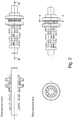
- FIGS. 1 and 2 show once the prior art ( FIG. 3 ) and in two representations the idea according to the invention ( FIGS. 1 and 2 ).
- the spout 10 has two flanges 22, 24, which are connected to each other fully and continuously, this continuous connection region forms a groove bottom 24 (see also FIG. 3 of the prior art). From this groove bottom 24 extend radially extending tooth-like elevations 26th
- FIG. 2 three-dimensional
- FIG. 3 show the solution according to the invention, wherein in this new spout 1, which is set analogously to the known from the prior art grommet on an electric cable 2, a Spout geometry 3 and two flanges 4, 5 are present, the at least one Connecting web 6, preferably a plurality of connecting webs 6 (as shown in the embodiment), are connected with the realization of material recesses between the webs.
- the recess extends, laterally delimited by the two flanges 4, 5 and the at least one connecting web 6, radially from the outside continuously in the direction of the electric cable. 2
- At least one parallel web 7 is arranged, which is connected via the at least one connecting web 6, preferably a plurality of connecting webs 6, with the two flanges 4, 5.
Landscapes
- Engineering & Computer Science (AREA)
- Mechanical Engineering (AREA)
- Installation Of Indoor Wiring (AREA)
- Insulating Bodies (AREA)
- Nozzles (AREA)
Abstract
Description
- Die Erfindung betrifft eine Befestigungsanordnung mit einer Tülle, die an einem Befestigungselement festgelegt werden soll, wobei die Tülle zwei gegenüberliegende beabstandete Flansche aufweist, die zur Anlage an die Oberfläche des Befestigungselementes kommen, wenn die Tülle dort festgelegt worden ist, gemäß den Merkmalen des Oberbegriffes des Patentanspruches 1.
- Aus der
EP 2 069 167 B1 ist eine Befestigungseinrichtung für eine Leitung, insbesondere für ein elektrisches Kabel in einem Kraftfahrzeug bekannt, mit einer in einem Halter arretierbaren, die Leitung wenigstens teilweise umschließenden Tülle aus elastisch verformbarem Material, welche mittels einer Tüllenkontur in einer Aussparung des Halters lösbar befestigt ist, wobei die Tülle aus Kunststoff gespritzt und die Oberfläche der Tüllenkontur segmentiert und nutförmig ausgebildet ist mit zahnartigen Erhebungen an einem Nutgrund. - Die
Figur 3 nebst zugehöriger Beschreibung dieses europäischen Patentes offenbart ein elektrisches Kabel 12, auf welches eine Tülle 10 ausgebracht ist. Die Tüllenkontur 14 ist nutförmig ausgebildet mit zahnartigen Erhebungen 26 an einem Nutgrund 24, wobei der Nutgrund 24 von der Tülle 10 gebildet ist. Das bedeutet, dass die Tüllenkontur 14 zwischen den beiden Flanschen 20, 22 durchgehend
ohne Unterbrechungen ausgebildet ist, wobei dieser durchgängige Bereich zwischen den beiden Flanschen 20, 22 den Nutgrund der Tüllenkonfur bildet. Ausgehend von diesem von der Tülle selber gebildeten Nutgrund erstrecken sich die Erhebungen für die beschriebene Festlegung der Tülle in dem Befestigungselement. Das bedeutet, dass die in Richtung des Kabels weisenden Flächen der beiden Flansche sowie die in die gleiche Richtung weisende Fläche des Nutgrundes eine geschlossene durchgehende Fläche bilden, die auf dem Kabel, genauer dessen Kabelmantel, aufliegen, wenn die Tülle auf das Kabel aufgeschoben worden ist. - Das Vorhandensein eines durchgehenden Bereiches (durchgehende Fläche) von Tüllenmaterial zwischen den beiden Flanschen führt zu einer Erhöhung der Befestigungskräfte, wenn die Tülle in dem Befestigungselement eingesetzt werden soll, da trotz Verwendung von elastischem Material für die Tülle keine ausreichend hohe Flexibilität zur Verfügung steht. Außerdem wird durch diesen durchgehenden Bereich der Tüllenkontur zwischen den beiden Flanschen das Gewicht der gesamten Tülle in unnötiger Weise erhöht, genauso wie der Materialeinsatz für die Realisierung der Tülle selber.
- Durch die Erfindung sollen die eingangs beschriebenen Nachteile vermieden werden.
- Dies wird durch die Merkmale des Patentanspruches 1 erreicht.
- Erfindungsgemäß ist eine Tülleneinknüpfgeometrie zur Leitungsabstützung vorgesehen, bei der eine Materialaussparung zwischen den beiden Flanschen vorgesehen ist. Die Tülle ist zur Festlegung an dem Befestigungselement dadurch realisiert, dass die beiden Flansche, die zur Anlage an das Befestigungselement nach der Montage kommen, durch mindestens einen Verbindungssteg,
vorzugsweise mehrere Verbindungsstege, miteinander verbunden sind. Zwischen den Verbindungsstegen ist eine Materialaussparung vorhanden, so dass Freiräume zwischen den beiden Flanschen bis in Richtung des Kabelmantels der elektrischen Leitung gegeben sind. Die Aussparung ist somit in radialer Ausrichtung von außen in Richtung des elektrischen Kabels durchgehend vorhanden. Es ist somit keine umlaufende Nut und folglich auch kein umlaufender oder teilweise gegebener Nutgrund vorhanden. Lediglich der in Richtung des elektrischen Kabels weisende Endbereich des zumindest einen Verbindungssteges kommt zur Anlage an das Kabel, insbesondere dessen Kabelmantel. Durch diese Freiräume zwischen den beiden Flanschen zwischen den vorzugsweise mehreren Verbindungsstegen wird das Material der Tülle in vorteilhafter Weise reduziert, genauso wie die Kräfte, die erforderlich sind, wenn die Tülle in die Öffnung des Befestigungselementes eingesetzt werden soll. - In Weiterbildung der Erfindung ist vorgesehen, dass umlaufend zwischen den beiden Flanschen vier oder sechs Verbindungsstege angeordnet sind. Wie schon ausgeführt führt im Stand der Technik das Vorhandensein eines durchgehenden Bereiches (durchgehende Fläche) von Tüllenmaterial zwischen den beiden Flanschen zu einer Erhöhung der Befestigungskräfte, wenn die Tülle in dem Befestigungselement eingesetzt werden soll, da trotz Verwendung von elastischem Material für die Tülle keine ausreichend hohe Flexibilität zur Verfügung steht. Außerdem wird durch diesen durchgehenden Bereich der Tüllenkontur zwischen den beiden Flanschen das Gewicht der gesamten Tülle in unnötiger Weise erhöht, genauso wie der Materialeinsatz für die Realisierung der Tülle selber. Andererseits sollen die Montagekräfte nicht zu hoch und Gewicht gespart werden bei gleichzeitig ausreichend hohen Haltekräften der Tülle auf dem Kabel, um diese dauerhaft und möglichst unverschiebbar auf dem Kabel festzulegen. Für die Erreichung dieses Ziel bieten vier oder sechs Verbindungsstegen einen guten Kompromiss, da einerseits mittels der Aussparung nach der Erfindung Material gespart wird und die Montagekräfte reduziert werden, gleichzeitig durch die radial in Richtung des Kabels weisenden Flächen der vier oder sechs Verbindungsstege die Tülle dauerhaft und nahezu oder vollständig unverschiebbar auf dem Kabel festgelegt wird.
- In Weiterbildung der Erfindung ist vorgesehen, dass zwischen den beiden Flanschen zumindest ein Parallelsteg angeordnet ist, der über den zumindest einen Verbindungssteg, vorzugsweise mehrere Verbindungsstege, mit den beiden Flanschen verbunden ist. Diesbezüglich gilt das Gleiche, wie zuvor schon bezüglich der Verbindungsstege, die die Aussparung(en) bildet, ausgeführt.
- Die drei Figuren zeigen einmal den Stand der Technik (
Figur 3 ) und in zwei Darstellungen die erfindungsgemäße Idee (Figuren 1 und2 ). - Bei der den Stand der Technik beschreibenden und zeigenden
Figur 3 ist erkennbar, dass die Tülle 10 zwei Flansche 22, 24 aufweist, die vollumfänglich und durchgehend miteinander verbunden sind, wobei dieser durchgehende Verbindungsbereich einen Nutgrund 24 bildet (siehe auchFigur 3 des Standes der Technik). Von diesem Nutgrund 24 aus erstrecken sich radial verlaufend zahnartige Erhebungen 26. - Die
Figur 2 (dreidimensional) und dieFigur 3 (Strichdarstellung) zeigen die erfindungsgemäße Lösung, wobei bei dieser neuen Tülle 1, die analog zu der aus dem Stand der Technik bekannten Tülle auf einem elektrischen Kabel 2 festgelegt wird, eine Tüllengeometrie 3 und zwei Flansche 4, 5 vorhanden sind, die über zumindest einen Verbindungssteg 6, vorzugsweise mehrere Verbindungsstege 6 (wie in dem Ausführungsbeispiel dargestellt), unter Realisierung von Materialaussparungen zwischen den Stegen verbunden sind. Bei dieser Variante gibt es keinen Nutgrund, von dem aus sich zahnartige Erhebungen aus erstrecken können. Die Aussparung erstreckt sich, seitlich begrenzt von den beiden Flanschen 4, 5 sowie dem zumindest einen Verbindungssteg 6, radial von außen durchgehend in Richtung des elektrischen Kabels 2. - Außerdem ist erkennbar, dass zwischen den beiden Flanschen 4, 5 zumindest ein Parallelsteg 7 angeordnet ist, der über den zumindest einen Verbindungssteg 6, vorzugsweise mehrere Verbindungsstege 6, mit den beiden Flanschen 4, 5 verbunden ist.
-
- 10.
- Tülle
- 12.
- Elektrisches Kabel
- 14.
- Tüllenkontur
- 20.
- Flansch
- 22.
- Flansch
- 24.
- Nutgrund
- 26.
- Zahnartige Erhebung
- 1.
- Tülle
- 2.
- Elektrisches Kabel
- 3.
- Tüllengeometrie
- 4.
- Flansch
- 5.
- Flansch
- 6.
- Verbindungssteg
- 7.
- Parallelsteg
Claims (3)
- Befestigungsanordnung mit einer Tülle (1), die an einem Befestigungselement festgelegt werden soll, wobei die Tülle (1) zwei gegenüberliegende beabstandete Flansche (4, 5) aufweist, die zur Anlage an die Oberfläche des Befestigungselementes kommen, wenn die Tülle (1) dort festgelegt worden ist, dadurch gekennzeichnet dass die beiden Flansche (4, 5) unter Bildung von Aussparungen durch zumindest einen Verbindungssteg (6), vorzugsweise mehrere Verbindungsstege (6), miteinander verbunden sind.
- Befestigungsanordnung nach Anspruch 1, dadurch gekennzeichnet, dass umlaufend zwischen den beiden Flanschen (4, 5) vier oder sechs Verbindungsstege (6) angeordnet sind.
- Befestigungsanordnung nach Anspruch 1 oder 2, dadurch gekennzeichnet, dass zwischen den beiden Flanschen (4, 5) zumindest ein Parallelsteg (7) angeordnet ist, der über den zumindest einen Verbindungssteg (6), vorzugsweise mehrere Verbindungsstege (6), mit den beiden Flanschen (4, 5) verbunden ist.
Applications Claiming Priority (1)
| Application Number | Priority Date | Filing Date | Title |
|---|---|---|---|
| DE102016117902 | 2016-09-22 |
Publications (2)
| Publication Number | Publication Date |
|---|---|
| EP3299222A1 true EP3299222A1 (de) | 2018-03-28 |
| EP3299222B1 EP3299222B1 (de) | 2019-11-06 |
Family
ID=59968957
Family Applications (1)
| Application Number | Title | Priority Date | Filing Date |
|---|---|---|---|
| EP17192287.5A Active EP3299222B1 (de) | 2016-09-22 | 2017-09-21 | Verbesserte tülleneinknüpfgeometrie zur leitungsabstützung |
Country Status (3)
| Country | Link |
|---|---|
| EP (1) | EP3299222B1 (de) |
| DE (1) | DE102017121874A1 (de) |
| ES (1) | ES2759482T3 (de) |
Families Citing this family (1)
| Publication number | Priority date | Publication date | Assignee | Title |
|---|---|---|---|---|
| CN113612176A (zh) * | 2021-08-05 | 2021-11-05 | 广东电网有限责任公司江门供电局 | 一种发电车电缆临时封堵装置 |
Citations (5)
| Publication number | Priority date | Publication date | Assignee | Title |
|---|---|---|---|---|
| DE1925877U (de) * | 1965-08-07 | 1965-10-28 | Willi Ruebsamen | Isoliertuelle zum durchfuehren und festlegen von elektrischen leitungen bzw. kabeln. |
| JPS55169017U (de) * | 1979-05-24 | 1980-12-04 | ||
| DE4233472A1 (de) * | 1991-10-04 | 1993-04-08 | Itw De France | Deckel fuer eine oeffnung in einem blech |
| EP2069167B1 (de) | 2006-09-12 | 2013-09-11 | Robert Bosch GmbH | Befestigungseinrichtung für eine leitung |
| JP2013183498A (ja) * | 2012-02-29 | 2013-09-12 | Hitachi Cable Ltd | グロメット付ケーブル |
-
2017
- 2017-09-21 EP EP17192287.5A patent/EP3299222B1/de active Active
- 2017-09-21 ES ES17192287T patent/ES2759482T3/es active Active
- 2017-09-21 DE DE102017121874.2A patent/DE102017121874A1/de not_active Withdrawn
Patent Citations (5)
| Publication number | Priority date | Publication date | Assignee | Title |
|---|---|---|---|---|
| DE1925877U (de) * | 1965-08-07 | 1965-10-28 | Willi Ruebsamen | Isoliertuelle zum durchfuehren und festlegen von elektrischen leitungen bzw. kabeln. |
| JPS55169017U (de) * | 1979-05-24 | 1980-12-04 | ||
| DE4233472A1 (de) * | 1991-10-04 | 1993-04-08 | Itw De France | Deckel fuer eine oeffnung in einem blech |
| EP2069167B1 (de) | 2006-09-12 | 2013-09-11 | Robert Bosch GmbH | Befestigungseinrichtung für eine leitung |
| JP2013183498A (ja) * | 2012-02-29 | 2013-09-12 | Hitachi Cable Ltd | グロメット付ケーブル |
Also Published As
| Publication number | Publication date |
|---|---|
| EP3299222B1 (de) | 2019-11-06 |
| DE102017121874A1 (de) | 2018-03-22 |
| ES2759482T3 (es) | 2020-05-11 |
Similar Documents
| Publication | Publication Date | Title |
|---|---|---|
| DE2337417B2 (de) | Vorrichtung zur befestigung von kabeln u.dgl. | |
| DE202012001760U1 (de) | Kabelführung | |
| DE102015008877A1 (de) | Modulare Gleit- oder Spannschiene | |
| DE1475035B2 (de) | Befestigungsvorrichtung | |
| DE102015110162A1 (de) | Energieführungskette | |
| DE2518332A1 (de) | Verteilungsstab fuer leitungsanschlusstellen | |
| EP3299222B1 (de) | Verbesserte tülleneinknüpfgeometrie zur leitungsabstützung | |
| DE202013012278U1 (de) | Winkelsteckverbinder mit einstellbarer Abgangsrichtung | |
| DE2714861A1 (de) | Reibungskupplung | |
| DE102007029410B4 (de) | Befestigungsklammer | |
| EP2598761A1 (de) | Vorrichtung zum aufstecken auf einen gewindebolzen | |
| DE102007016484B4 (de) | Lösbarer Spreizclip für eine Clipsverbindung mehrerer Bauteile | |
| EP2848839B1 (de) | Vorrichtung zum befestigen eines drahtseils | |
| EP0655300A1 (de) | Vorrichtung zur Befestigung eines Rohres in einem Hülsenteil | |
| EP2887463B1 (de) | Winkelsteckverbinder mit einstellbarer Abgangsrichtung | |
| DE102013223593A1 (de) | Verschlusskappe | |
| DE202011106764U1 (de) | Befestigungsvorrichtung | |
| DE102017002558A1 (de) | Mastklammer und damit herstellbare Mastanordnung | |
| DE19713772A1 (de) | Dachreling für Fahrzeuge | |
| DE202014007055U1 (de) | Kabeldurchführung | |
| DE102020210570A1 (de) | Gliederschürze zum Abdecken von Öffnungen und Abdeckvorrichtung für Öffnungen | |
| DE8317937U1 (de) | Kunststoff-Clip zur Befestigung von Bauteilen an einer tragenden dünnwandigen Unterlage | |
| DE102018111372A1 (de) | Linearaktuator | |
| DE202019102228U1 (de) | Montageeinrichtung für Fertigbauelemente | |
| DE102016201631A1 (de) | Federanordnung, Federbein sowie Kraftfahrzeug |
Legal Events
| Date | Code | Title | Description |
|---|---|---|---|
| PUAI | Public reference made under article 153(3) epc to a published international application that has entered the european phase |
Free format text: ORIGINAL CODE: 0009012 |
|
| STAA | Information on the status of an ep patent application or granted ep patent |
Free format text: STATUS: THE APPLICATION HAS BEEN PUBLISHED |
|
| AK | Designated contracting states |
Kind code of ref document: A1 Designated state(s): AL AT BE BG CH CY CZ DE DK EE ES FI FR GB GR HR HU IE IS IT LI LT LU LV MC MK MT NL NO PL PT RO RS SE SI SK SM TR |
|
| AX | Request for extension of the european patent |
Extension state: BA ME |
|
| STAA | Information on the status of an ep patent application or granted ep patent |
Free format text: STATUS: REQUEST FOR EXAMINATION WAS MADE |
|
| 17P | Request for examination filed |
Effective date: 20180412 |
|
| RBV | Designated contracting states (corrected) |
Designated state(s): AL AT BE BG CH CY CZ DE DK EE ES FI FR GB GR HR HU IE IS IT LI LT LU LV MC MK MT NL NO PL PT RO RS SE SI SK SM TR |
|
| GRAP | Despatch of communication of intention to grant a patent |
Free format text: ORIGINAL CODE: EPIDOSNIGR1 |
|
| STAA | Information on the status of an ep patent application or granted ep patent |
Free format text: STATUS: GRANT OF PATENT IS INTENDED |
|
| INTG | Intention to grant announced |
Effective date: 20190514 |
|
| GRAS | Grant fee paid |
Free format text: ORIGINAL CODE: EPIDOSNIGR3 |
|
| GRAA | (expected) grant |
Free format text: ORIGINAL CODE: 0009210 |
|
| STAA | Information on the status of an ep patent application or granted ep patent |
Free format text: STATUS: THE PATENT HAS BEEN GRANTED |
|
| AK | Designated contracting states |
Kind code of ref document: B1 Designated state(s): AL AT BE BG CH CY CZ DE DK EE ES FI FR GB GR HR HU IE IS IT LI LT LU LV MC MK MT NL NO PL PT RO RS SE SI SK SM TR |
|
| REG | Reference to a national code |
Ref country code: GB Ref legal event code: FG4D Free format text: NOT ENGLISH |
|
| REG | Reference to a national code |
Ref country code: CH Ref legal event code: EP Ref country code: AT Ref legal event code: REF Ref document number: 1198313 Country of ref document: AT Kind code of ref document: T Effective date: 20191115 |
|
| REG | Reference to a national code |
Ref country code: DE Ref legal event code: R096 Ref document number: 502017002794 Country of ref document: DE |
|
| REG | Reference to a national code |
Ref country code: IE Ref legal event code: FG4D Free format text: LANGUAGE OF EP DOCUMENT: GERMAN |
|
| REG | Reference to a national code |
Ref country code: RO Ref legal event code: EPE |
|
| REG | Reference to a national code |
Ref country code: NL Ref legal event code: MP Effective date: 20191106 |
|
| REG | Reference to a national code |
Ref country code: LT Ref legal event code: MG4D |
|
| PG25 | Lapsed in a contracting state [announced via postgrant information from national office to epo] |
Ref country code: PL Free format text: LAPSE BECAUSE OF FAILURE TO SUBMIT A TRANSLATION OF THE DESCRIPTION OR TO PAY THE FEE WITHIN THE PRESCRIBED TIME-LIMIT Effective date: 20191106 Ref country code: GR Free format text: LAPSE BECAUSE OF FAILURE TO SUBMIT A TRANSLATION OF THE DESCRIPTION OR TO PAY THE FEE WITHIN THE PRESCRIBED TIME-LIMIT Effective date: 20200207 Ref country code: NO Free format text: LAPSE BECAUSE OF FAILURE TO SUBMIT A TRANSLATION OF THE DESCRIPTION OR TO PAY THE FEE WITHIN THE PRESCRIBED TIME-LIMIT Effective date: 20200206 Ref country code: PT Free format text: LAPSE BECAUSE OF FAILURE TO SUBMIT A TRANSLATION OF THE DESCRIPTION OR TO PAY THE FEE WITHIN THE PRESCRIBED TIME-LIMIT Effective date: 20200306 Ref country code: SE Free format text: LAPSE BECAUSE OF FAILURE TO SUBMIT A TRANSLATION OF THE DESCRIPTION OR TO PAY THE FEE WITHIN THE PRESCRIBED TIME-LIMIT Effective date: 20191106 Ref country code: LV Free format text: LAPSE BECAUSE OF FAILURE TO SUBMIT A TRANSLATION OF THE DESCRIPTION OR TO PAY THE FEE WITHIN THE PRESCRIBED TIME-LIMIT Effective date: 20191106 Ref country code: FI Free format text: LAPSE BECAUSE OF FAILURE TO SUBMIT A TRANSLATION OF THE DESCRIPTION OR TO PAY THE FEE WITHIN THE PRESCRIBED TIME-LIMIT Effective date: 20191106 Ref country code: BG Free format text: LAPSE BECAUSE OF FAILURE TO SUBMIT A TRANSLATION OF THE DESCRIPTION OR TO PAY THE FEE WITHIN THE PRESCRIBED TIME-LIMIT Effective date: 20200206 Ref country code: LT Free format text: LAPSE BECAUSE OF FAILURE TO SUBMIT A TRANSLATION OF THE DESCRIPTION OR TO PAY THE FEE WITHIN THE PRESCRIBED TIME-LIMIT Effective date: 20191106 Ref country code: NL Free format text: LAPSE BECAUSE OF FAILURE TO SUBMIT A TRANSLATION OF THE DESCRIPTION OR TO PAY THE FEE WITHIN THE PRESCRIBED TIME-LIMIT Effective date: 20191106 |
|
| REG | Reference to a national code |
Ref country code: ES Ref legal event code: FG2A Ref document number: 2759482 Country of ref document: ES Kind code of ref document: T3 Effective date: 20200511 |
|
| PG25 | Lapsed in a contracting state [announced via postgrant information from national office to epo] |
Ref country code: RS Free format text: LAPSE BECAUSE OF FAILURE TO SUBMIT A TRANSLATION OF THE DESCRIPTION OR TO PAY THE FEE WITHIN THE PRESCRIBED TIME-LIMIT Effective date: 20191106 Ref country code: HR Free format text: LAPSE BECAUSE OF FAILURE TO SUBMIT A TRANSLATION OF THE DESCRIPTION OR TO PAY THE FEE WITHIN THE PRESCRIBED TIME-LIMIT Effective date: 20191106 Ref country code: IS Free format text: LAPSE BECAUSE OF FAILURE TO SUBMIT A TRANSLATION OF THE DESCRIPTION OR TO PAY THE FEE WITHIN THE PRESCRIBED TIME-LIMIT Effective date: 20200306 |
|
| PG25 | Lapsed in a contracting state [announced via postgrant information from national office to epo] |
Ref country code: AL Free format text: LAPSE BECAUSE OF FAILURE TO SUBMIT A TRANSLATION OF THE DESCRIPTION OR TO PAY THE FEE WITHIN THE PRESCRIBED TIME-LIMIT Effective date: 20191106 |
|
| PG25 | Lapsed in a contracting state [announced via postgrant information from national office to epo] |
Ref country code: EE Free format text: LAPSE BECAUSE OF FAILURE TO SUBMIT A TRANSLATION OF THE DESCRIPTION OR TO PAY THE FEE WITHIN THE PRESCRIBED TIME-LIMIT Effective date: 20191106 Ref country code: DK Free format text: LAPSE BECAUSE OF FAILURE TO SUBMIT A TRANSLATION OF THE DESCRIPTION OR TO PAY THE FEE WITHIN THE PRESCRIBED TIME-LIMIT Effective date: 20191106 |
|
| REG | Reference to a national code |
Ref country code: DE Ref legal event code: R097 Ref document number: 502017002794 Country of ref document: DE |
|
| PG25 | Lapsed in a contracting state [announced via postgrant information from national office to epo] |
Ref country code: SK Free format text: LAPSE BECAUSE OF FAILURE TO SUBMIT A TRANSLATION OF THE DESCRIPTION OR TO PAY THE FEE WITHIN THE PRESCRIBED TIME-LIMIT Effective date: 20191106 Ref country code: SM Free format text: LAPSE BECAUSE OF FAILURE TO SUBMIT A TRANSLATION OF THE DESCRIPTION OR TO PAY THE FEE WITHIN THE PRESCRIBED TIME-LIMIT Effective date: 20191106 |
|
| PLBE | No opposition filed within time limit |
Free format text: ORIGINAL CODE: 0009261 |
|
| STAA | Information on the status of an ep patent application or granted ep patent |
Free format text: STATUS: NO OPPOSITION FILED WITHIN TIME LIMIT |
|
| 26N | No opposition filed |
Effective date: 20200807 |
|
| PG25 | Lapsed in a contracting state [announced via postgrant information from national office to epo] |
Ref country code: SI Free format text: LAPSE BECAUSE OF FAILURE TO SUBMIT A TRANSLATION OF THE DESCRIPTION OR TO PAY THE FEE WITHIN THE PRESCRIBED TIME-LIMIT Effective date: 20191106 |
|
| REG | Reference to a national code |
Ref country code: CH Ref legal event code: PL |
|
| REG | Reference to a national code |
Ref country code: BE Ref legal event code: MM Effective date: 20200930 |
|
| PG25 | Lapsed in a contracting state [announced via postgrant information from national office to epo] |
Ref country code: LU Free format text: LAPSE BECAUSE OF NON-PAYMENT OF DUE FEES Effective date: 20200921 |
|
| PG25 | Lapsed in a contracting state [announced via postgrant information from national office to epo] |
Ref country code: IE Free format text: LAPSE BECAUSE OF NON-PAYMENT OF DUE FEES Effective date: 20200921 Ref country code: LI Free format text: LAPSE BECAUSE OF NON-PAYMENT OF DUE FEES Effective date: 20200930 Ref country code: BE Free format text: LAPSE BECAUSE OF NON-PAYMENT OF DUE FEES Effective date: 20200930 Ref country code: CH Free format text: LAPSE BECAUSE OF NON-PAYMENT OF DUE FEES Effective date: 20200930 |
|
| PG25 | Lapsed in a contracting state [announced via postgrant information from national office to epo] |
Ref country code: TR Free format text: LAPSE BECAUSE OF FAILURE TO SUBMIT A TRANSLATION OF THE DESCRIPTION OR TO PAY THE FEE WITHIN THE PRESCRIBED TIME-LIMIT Effective date: 20191106 Ref country code: MT Free format text: LAPSE BECAUSE OF FAILURE TO SUBMIT A TRANSLATION OF THE DESCRIPTION OR TO PAY THE FEE WITHIN THE PRESCRIBED TIME-LIMIT Effective date: 20191106 Ref country code: CY Free format text: LAPSE BECAUSE OF FAILURE TO SUBMIT A TRANSLATION OF THE DESCRIPTION OR TO PAY THE FEE WITHIN THE PRESCRIBED TIME-LIMIT Effective date: 20191106 |
|
| PG25 | Lapsed in a contracting state [announced via postgrant information from national office to epo] |
Ref country code: MK Free format text: LAPSE BECAUSE OF FAILURE TO SUBMIT A TRANSLATION OF THE DESCRIPTION OR TO PAY THE FEE WITHIN THE PRESCRIBED TIME-LIMIT Effective date: 20191106 Ref country code: MC Free format text: LAPSE BECAUSE OF FAILURE TO SUBMIT A TRANSLATION OF THE DESCRIPTION OR TO PAY THE FEE WITHIN THE PRESCRIBED TIME-LIMIT Effective date: 20191106 |
|
| PGFP | Annual fee paid to national office [announced via postgrant information from national office to epo] |
Ref country code: RO Payment date: 20230913 Year of fee payment: 7 Ref country code: GB Payment date: 20230920 Year of fee payment: 7 Ref country code: CZ Payment date: 20230912 Year of fee payment: 7 |
|
| REG | Reference to a national code |
Ref country code: AT Ref legal event code: MM01 Ref document number: 1198313 Country of ref document: AT Kind code of ref document: T Effective date: 20220921 |
|
| PGFP | Annual fee paid to national office [announced via postgrant information from national office to epo] |
Ref country code: FR Payment date: 20230928 Year of fee payment: 7 Ref country code: DE Payment date: 20230920 Year of fee payment: 7 |
|
| PGFP | Annual fee paid to national office [announced via postgrant information from national office to epo] |
Ref country code: ES Payment date: 20231124 Year of fee payment: 7 |
|
| PG25 | Lapsed in a contracting state [announced via postgrant information from national office to epo] |
Ref country code: AT Free format text: LAPSE BECAUSE OF NON-PAYMENT OF DUE FEES Effective date: 20220921 |
|
| PGFP | Annual fee paid to national office [announced via postgrant information from national office to epo] |
Ref country code: IT Payment date: 20230927 Year of fee payment: 7 |