EP2848839B1 - Vorrichtung zum befestigen eines drahtseils - Google Patents
Vorrichtung zum befestigen eines drahtseils Download PDFInfo
- Publication number
- EP2848839B1 EP2848839B1 EP14181932.6A EP14181932A EP2848839B1 EP 2848839 B1 EP2848839 B1 EP 2848839B1 EP 14181932 A EP14181932 A EP 14181932A EP 2848839 B1 EP2848839 B1 EP 2848839B1
- Authority
- EP
- European Patent Office
- Prior art keywords
- clamping
- clamping jaws
- screws
- bollard
- wire rope
- Prior art date
- Legal status (The legal status is an assumption and is not a legal conclusion. Google has not performed a legal analysis and makes no representation as to the accuracy of the status listed.)
- Not-in-force
Links
Images
Classifications
-
- F—MECHANICAL ENGINEERING; LIGHTING; HEATING; WEAPONS; BLASTING
- F16—ENGINEERING ELEMENTS AND UNITS; GENERAL MEASURES FOR PRODUCING AND MAINTAINING EFFECTIVE FUNCTIONING OF MACHINES OR INSTALLATIONS; THERMAL INSULATION IN GENERAL
- F16G—BELTS, CABLES, OR ROPES, PREDOMINANTLY USED FOR DRIVING PURPOSES; CHAINS; FITTINGS PREDOMINANTLY USED THEREFOR
- F16G11/00—Means for fastening cables or ropes to one another or to other objects; Caps or sleeves for fixing on cables or ropes
- F16G11/06—Means for fastening cables or ropes to one another or to other objects; Caps or sleeves for fixing on cables or ropes with laterally-arranged screws
Definitions
- the invention relates to a device for fastening a wire rope, with clamping jaws which can be pressed onto the wire rope with tensioning screws.
- Such devices are used, for example, for fastening, tensioning or pulling steel cables in supporting structures of large-area roofs, suspension bridges and cable cars, this being done in particular during the assembly or maintenance of the systems.
- the ropes used for this often have a relatively large diameter and are also exposed to high tensile forces.
- the pamphlet GB-A-1 535 189 relates to a cable clamp, in which a base member and two arms articulated on this are present, which can be fastened to one another at the opposite end by means of a screw connection. Both the base member and the arms are each provided with jaws which are shaped on the inside according to the diameters of the cables.
- a single screw connection is provided, by means of which an insufficient clamping force can be generated for use with wire ropes, for example for aerial cableways.
- the invention is based on the object of creating a device of the type mentioned at the outset which has a relatively light, compact and structurally simple structure and efficiently implements the frictional connection with the rope.
- the device is formed by clamping jaws provided in pairs with an approximately trapezoidal cross-section, the inner narrow sides of which encompass the rope in two mutually perpendicular diametrical planes and whose outer broad sides serve as support surfaces for the tensioning screws, which are preferably arranged in two rows, the tensioning screws of one pair of jaws are guided through the spaces between the clamping screws of the other pair of jaws to save space.
- the pretensioning force of the tensioning screws into the rope in the best possible way at the apex of the rope underneath in the same direction at at least four points.
- the preload force can be increased by inserting several pairs of jaws in the The same length of the rope is increased several times over conventional clamping plates and the dead weight of the clamping jaws can be minimized while maintaining the required strength.
- the device is also very compact due to the trapezoidal jaw cross-section and can therefore be used in a space-saving manner. This is particularly the case when the device in the assembled state forms a prismatic body which is provided with parting lines running diagonally between the clamping jaws.
- the clamping jaws can be pressed evenly and firmly against the rope. Thanks to the diagonal separating joints, this also applies to a certain extent for different diameters of the rope.
- clamping screws are evenly distributed over the effective overall length of the clamping jaws, with each row of clamping screws preferably containing the same number of clamping screws. This number is expediently determined as a function of the diameter and / or the tensile stress of the rope to be fastened.
- clamping jaws on their narrow longitudinal sides with inserts that extend over the effective overall length of the clamping jaws, the material of these inserts forming an optimal form and friction fit on the contact surfaces.
- the clamping device In order to anchor the clamping plate as a result of the cable pull, it can be supported at the front or tensioned via attached bollard plates and via cable troops in the opposite direction of the cable pulling force.
- the clamping device is preferably provided at one end of the device with two bollard plates attached to it, four clamping screws of the clamping device serving as fastening means, which in this case are not supported directly against the clamping jaws but against the bollard plates.
- the latter are expediently disc-shaped and have a circumferential annular groove to accommodate the cable troop.
- the bollard plates are provided with corresponding cams which engage in corresponding recesses in the clamping jaws.
- the bollard guying device is integrated into the clamping device without the form fit between the two devices impairing the clamping effect of the clamping jaws.
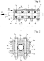
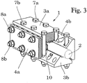
- FIGS. 1 to 3 show a clamping device 1 for fastening a wire rope 2. It consists of two pairs of clamping jaws 3a, 3b and 4a, 4b with a trapezoidal cross-section, the inner narrow sides 5 of which encompass the wire rope 2 in two mutually perpendicular planes and the outer broad sides 6 as supporting surfaces for two rows arranged clamping screws 7a, 7b or 8a, 8b are used, the clamping screws 7a, 7b of one pair of clamping jaws 3a, 3b being guided through the spaces between the clamping screws 8a, 8b of the other pair of clamping jaws 4a, 4b.
- the dimensioning of these spaces is coordinated with that of the clamping jaw cross-section so that the clamping jaws can apply the required strength with the lowest possible weight.
- the clamping device according to the invention thus also has the advantage that the tensioning force of the screw pairs is ideally introduced at at least four points on the rope circumference parallel to the direction of pull, directly at the apex, in contrast to conventional devices, because the pretensioning force can be applied in the same rope section through the clamping effect of several pairs of jaws can be increased several times. This reduces the overall length with the same pulling force and at the same time improves the efficiency with regard to frictional engagement.
- a prismatic body with an approximately quadrangular cross-section, which is provided with diagonally running separating joints 9 between the clamping jaws 3a, 3b and 4a, 4b.
- the latter allow a mutual displacement of the clamping jaws.
- the device can thus be used within certain limits for wire ropes with different diameters.
- the clamping jaws 3a, 3b and 4a, 4b are provided on their narrow longitudinal side with inserts 10, which extend over the effective overall length of the clamping jaws and are made of a material suitable for rope and frictional engagement.
- the inserts 10 have slightly rounded engagement surfaces, the curvature of which corresponds to that of the rope circumference.
- the wire rope is thus clamped with a uniform, large-area clamping effect.
- the selection of the core material depends on the nature of the wire rope.
- the clamping screws 7a, 7b are arranged in each row evenly distributed over the entire effective overall length of the clamping jaws, each row containing the same number of clamping screws. In this way, a completely uniform clamping effect can be achieved.
- the number and / or strength of the tensioning screws can be determined from case to case depending on the diameter and / or the tensile stress of the wire rope.
- the device 1 For tensioning the wire rope 2, the device 1 is supported against the support surface provided on the end face of a holding element 20 which counteracts the tensile force Z of the wire rope with an opposing reaction force R.
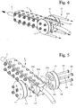
- the variant according to FIGS. 4 and 5 differs from the clamping device according to FIGS. 1 to 3 only in that it is provided at one end of the device with preferably two bollard plates 11, 12 of a bollard bracing device 13 attached to it, four clamping screws 28 of the clamping device 1 serving as fastening means, which in this case not directly against the clamping jaws 3a, 3b or 4a, 4b, but are pressed against the outer surfaces of the bollard plates 11, 12.
- the latter are circular and have a circumferential annular groove 14 for receiving a cable pull, for example in the form of guy forces 15a, 15b with which the wire rope 2 is tensioned by means of a pulley block, not shown.
- the bollard plates 11 and 12 are installed at the front end of the clamping device. But it is also possible to place them approximately in the center of the clamping device by moving the bores 17 and the grooves 19a, 19b to the center of the clamping jaws.
- the tensioning screws used to fasten the bollard plates naturally have a greater overall length than the other tensioning screws.
- a device could also be assigned more than two clamping jaws provided in pairs.
Landscapes
- Engineering & Computer Science (AREA)
- General Engineering & Computer Science (AREA)
- Mechanical Engineering (AREA)
- Mutual Connection Of Rods And Tubes (AREA)
- Refuge Islands, Traffic Blockers, Or Guard Fence (AREA)
- Clamps And Clips (AREA)
Description
- Die Erfindung betrifft eine Vorrichtung zum Befestigen eines Drahtseils, mit Klemmbacken, die mit Spannschrauben an das Drahtseil anpressbar sind.
- Derartige Vorrichtungen werden beispielsweise zum Befestigen, Spannen oder Ziehen von Stahlseilen in Tragstrukturen von grossflächigen Dächern, Hängebrücken und Seilbahnen eingesetzt, wobei dies insbesondere bei der Montage bzw. beim Unterhalt der Anlagen erfolgt. Die dafür verwendeten Seile haben oft einen relativ grossen Durchmesser und sind auch hohen Zugkräften ausgesetzt.
- Die Druckschrift
GB-A-1 535 189 - Im Dokument
DE 192 367 C ist eine Befestigung von Drahtseilen und Kabeln offenbart, bei der Einzelteile als Klemmen mit jeweils einer schrägen Fläche ausgebildet sind. Es sind vier solcher Einzelteile durch Schrauben paarweise zueinander befestigt, die je eine Klemmbacke bilden. Diese paarweisen Einzelteile sind dann mit den gegenüberliegenden paarweisen Einzelteilen in symmetrischer Anordnung ebenfalls durch Schrauben verbindbar und sie sind mit zwei in eine parallele Richtung verlaufende Bohrungen und mit einer Bohrung quer dazu versehen. Damit bewirken diese vier Einzelteile nur ein Klemmen wie ein einzelnes Paar von Klemmbacken. - Der Erfindung liegt die Aufgabe zugrunde, eine Vorrichtung der eingangs genannten Art zu schaffen, die einen verhältnismässig leichten, kompakten und konstruktiv einfachen Aufbau aufweist und den Reibschluss zum Seil effizient umsetzt.
- Diese Aufgabe wird erfindungsgemäss dadurch gelöst, dass die Vorrichtung durch paarweise vorgesehene Klemmbacken mit annähernd trapezförmigem Querschnitt gebildet ist, deren innere Schmalseiten das Seil in zwei senkrecht zueinander gerichteten Diametralebenen umfassen und deren äussere Breitseiten als Stützflächen für die vorzugsweise zweireihig angeordneten Spannschrauben dienen, wobei die Spannschrauben des einen Klemmbackenpaars raumsparend durch die Zwischenräume zwischen den Spannschrauben des anderen Klemmbackenpaars geführt sind.
- Es ist dabei zweckmässig, den Querschnitt der Klemmbacken und die Zwischenräume zwischen den Spannschrauben so aufeinander abzustimmen, dass die Klemmbacken möglichst kleinbauend sind, ohne ihre Festigkeit und die Bewegungsfreiheit zueinander zu beeinträchtigen.
- Es ist somit auf diese Weise möglich, die Vorspannkraft der Spannschrauben bestmöglich im Scheitelpunkt des darunter liegenden Seils gleichgerichtet an mindestens vier Punkten ins Seil einzuleiten. Zusätzlich kann die Vorspannkraft durch Einsetzen mehrerer Backenpaare im gleichen Längenabschnitt des Seils gegenüber herkömmlichen Klemmplatten um ein Mehrfaches erhöht und das Eigengewicht der Klemmbacken bei Einhaltung der erforderlichen Festigkeit merkbar minimiert werden.
- Die Vorrichtung ist zudem durch den trapezförmigen Klemmbackenquerschnitt sehr kompakt und kann dadurch platzsparend eingesetzt werden. Das ist insbesondere der Fall, wenn die Vorrichtung im zusammengebauten Zustand einen prismatischen Körper bildet, der mit zwischen den Klemmbacken diagonal verlaufenden Trennfugen versehen ist.
- Durch die zweireihige Anordnung der Spannschrauben können die Klemmbacken gleichmässig fest gegen das Seil angepresst werden. Dank der diagonal verlaufenden Trennfugen gilt das auch in einem bestimmten Umfang für abweichende Durchmesser des Seils.
- Es ist in diesem Sinne vorteilhaft, wenn die Spannschrauben gleichmässig über die wirksame Baulänge der Klemmbacken verteilt sind, wobei jede Reihe Spannschrauben vorzugsweise die gleiche Anzahl Spannschrauben beinhaltet. Diese Anzahl wird zweckmässigerweise in Abhängigkeit vom Durchmesser und/oder der Zugbeanspruchung des zu befestigenden Seils festgelegt.
- Zum Schonen des Seils ist es auch zweckmässig, die Klemmbacken an ihren schmalen Längsseiten mit über die wirksame Baulänge der Klemmbacken erstreckende Einlagen zu versehen, wobei das Material dieser Einlagen an den Kontaktflächen einen optimalen Form- und Reibschluss bildet.
- Zur Verankerung der Klemmplatte infolge des Seilzugs kann diese stirnseitig abgestützt oder über angebaute Pollerplatten und über Seilstruppen in Gegenrichtung der Seilzugkraft abgespannt werden. In diesem Fall sieht die Erfindung vor, dass die Klemmvorrichtung vorzugsweise an dem einen Vorrichtungsende mit zwei daran befestigten Pollerplatten versehen ist, wobei als Befestigungsmittel vier Spannschrauben der Klemmvorrichtung dienen, die in diesem Fall nicht direkt gegen die Klemmbacken, sondern gegen die Pollerplatten abgestützt sind. Letztere sind zweckmässigerweise scheibenförmig ausgebildet und weisen eine umfängliche Ringnut auf, dies zur Aufnahme der Seilstruppe.
- Zur Herstellung eines Formschlusses zwischen den Pollerplatten und der Vorrichtung sind die Pollerplatten mit entsprechenden Nocken versehen, die in entsprechende Aussparungen der Klemmbacken eingreifen. Auf diese Weise wird die Poller-Abspannvorrichtung in der Klemmvorrichtung integriert, ohne dass der Formschluss zwischen beiden Vorrichtungen die Klemmwirkung der Klemmbacken beeinträchtigt.
- Die Erfindung ist nachfolgend anhand von Ausführungsbeispielen unter Bezugnahme auf die Zeichnung näher erläutert. Es zeigen:
- Fig. 1
- eine erfindungsgemässe Klemmvorrichtung, in der Seitenansicht dargestellt,
- Fig. 2
- einen Schnitt durch die Klemmvorrichtung entlang der Linie II-II gemäss
Fig. 1 , - Fig. 3
- die Klemmvorrichtung nach
Fig. 1 teilweise im Schnitt und perspektivisch dargestellt, - Fig. 4
- eine perspektivisch gezeigte Variante einer Klemmvorrichtung aus
Fig. 1 mit integrierter Poller-Abspannvorrichtung, und - Fig. 5
- die Variante nach
Fig. 4 teilweise als Explosionszeichnung dargestellt. -
Fig. 1 bis Fig. 3 zeigen eine Klemmvorrichtung 1 zum Befestigen eines Drahtseils 2. Sie besteht aus zwei Paar Klemmbacken 3a, 3b und 4a, 4b mit trapezförmigem Querschnitt, deren inneren Schmalseiten 5 das Drahtseil 2 in zwei senkrecht zueinander gerichteten Ebenen umfassen und deren äusseren Breitseiten 6 als Stützflächen für zweireihig angeordnete Spannschrauben 7a, 7b bzw. 8a, 8b dienen, wobei die Spannschrauben 7a, 7b des einen Klemmbackenpaars 3a, 3b raumsparend durch die Zwischenräume zwischen den Spannschrauben 8a, 8b des anderen Klemmbackenpaars 4a, 4b geführt sind. - Die Dimensionierung dieser Zwischenräume ist mit der des Klemmbackenquerschnitts so abgestimmt, dass die Klemmbacken die erforderliche Festigkeit mit einem möglichst kleinen Eigengewicht aufbringen können. Die erfindungsgemässe Klemmvorrichtung hat somit zudem den Vorteil, dass die Spannkraft der Schraubenpaare an mindestens vier Stellen am Seilumfang parallel zur Zugrichtung direkt im Scheitelpunkt ideal eingeleitet wird, dies im Gegensatz zu herkömmlichen Vorrichtungen, denn es kann im gleichen Seilabschnitt durch die Klemmwirkung mehrerer Backenpaare die Vorspannkraft um ein mehrfaches erhöht werden. Hiermit wird die Gesamtbaulänge bei gleicher Seilzugkraft reduziert und zugleich die Effizienz bezüglich Reibschluss verbessert. Zwecks eines besonders kompakten Aufbaus bildet sie im zusammengebauten Zustand einen prismatischen Körper mit annähernd viereckigem Querschnitt, der zwischen den Klemmbacken 3a, 3b und 4a, 4b mit diagonal verlaufenden Trennfugen 9 versehen ist. Letztere ermöglichen eine gegenseitige Verschiebung der Klemmbacken. Die Vorrichtung ist dadurch innerhalb bestimmter Grenzen für Drahtseile mit abweichenden Durchmessern einsetzbar.
- Wie aus
Fig. 2 undFig. 3 ersichtlich, sind die Klemmbacken 3a, 3b bzw. 4a, 4b an ihrer schmalen Längsseite mit Einlagen10 versehen, die sich über die wirksame Baulänge der Klemmbacken erstrecken und aus einem für Seil und Reibschluss geeigneten Material hergestellt sind. Die Einlagen 10 weisen leicht abgerundete Eingriffsflächen auf, deren Krümmung mit der des Seilumfangs korrespondiert. Damit wird das Drahtseil mit einer gleichmässigen, grossflächigen Klemmwirkung festgeklemmt. Die Auswahl des Einlagenmaterials ist abhängig von der Beschaffenheit des Drahtseils. - Die Spannschrauben 7a, 7b sind in jeder Reihe gleichmässig verteilt über die gesamte wirksame Baulänge der Klemmbacken angeordnet, wobei jede Reihe die gleiche Anzahl Spannschrauben beinhaltet. Auf diese Weise ist eine vollumfänglich gleichmässige Klemmwirkung erzielbar. Die Anzahl und/oder Stärke der Spannschrauben kann von Fall zu Fall in Abhängigkeit vom Durchmesser und /oder der Zugbeanspruchung des Drahtseils festgelegt werden.
- Zum Aufspannen des Drahtseils 2 wird die Vorrichtung 1 gegen die stirnseitig vorgesehene Stützfläche eines Halteelements 20 abgestützt, welches der Zugkraft Z des Drahtseils mit einer entgegengerichteten Reaktionskraft R entgegenwirkt.
- Die Variante gemäss
Fig. 4 und Fig. 5 unterscheidet sich von der Klemmvorrichtung nachFig. 1 bis Fig. 3 lediglich dadurch, dass sie an dem einen Vorrichtungsende mit vorzugsweise zwei daran befestigten Pollerplatten 11, 12 einer Poller-Abspannvorrichtung 13 versehen ist, wobei als Befestigungsmittel vier Spannschrauben 28 der Klemmvorrichtung 1 dienen, die in diesem Fall nicht direkt gegen die Klemmbacken 3a, 3b bzw. 4a, 4b, sondern gegen die Aussenflächen der Pollerplatten 11, 12 angepresst sind. Letztere sind kreisförmig ausgebildet und weisen umfänglich eine Ringnut 14 auf zur Aufnahme eines Seilzugs beispielsweise in Gestalt von Abspannstruppen 15a, 15b, mit denen das Drahtseil 2 mittels eines nicht dargestellten Flaschenzugs gespannt ist. - Zur Positionierung und Befestigung der Pollerplatten 11, 12 an der Klemmvorrichtung 1 weisen sie mittig angeordnete Ansätze 16 auf, die in entsprechende Bohrungen 17 des einen Klemmbackenpaares 4a, 4b einführbar sind und mit je zwei U-förmigen Kupplungselementen 18a, 18b der Pollerplatten 11, 12 zusammenwirken, die ihrerseits in entsprechende Nuten 19a, 19b des anderen Klemmbackenpaars 3a, 3b koppelbar sind. Auf diese Weise entsteht zwischen der Klemmvorrichtung 1 und den Pollerplatten 11 und 12 eine formschlüssige Verbindung, welche jedoch die Klemmwirkung der Klemmbacken auf das Drahtseil 2 in keiner Weise beeinträchtigt.
- Beim beschriebenen Ausführungsbeispiel sind die Pollerplatten 11 und 12 am vorderen Ende der Klemmvorrichtung installiert. Es ist aber selbstverständlich im Rahmen der Erfindung auch möglich, sie etwa mittig in der Klemmvorrichtung zu platzieren, indem die Bohrungen 17 sowie die Nuten 19a, 19b auf die Klemmbackenmitte verlagert werden. Die zur Befestigung der Pollerplatten verwendeten Spannschrauben weisen naturgemäss eine grössere Baulänge auf als die übrigen Spannschrauben.
- Einer Vorrichtung könnten auch mehr als zwei paarweise vorgesehene Klemmbacken zugeordnet sein.
Claims (10)
- Vorrichtung zum Befestigen eines Drahtseils, mit Klemmbacken, die mit Spannschrauben an das Drahtseil anpressbar sind, wobei paarweise vorgesehene Klemmbacken (3a, 3b bzw. 4a, 4b) gebildet sind, dadurch gekennzeichnet, dass
die Vorrichtung durch zwei vorgesehene Klemmbackenpaare (3a, 3b bzw. 4a, 4b) gebildet ist, wobei deren Klemmbacken (3a, 3b bzw. 4a, 4b) mit je einem annähernd trapezförmigem Querschnitt gebildet sind, und die Vorrichtung im zusammengebauten Zustand einen prismatischen Körper mit annähernd viereckigem Querschnitt bildet, der mit zwischen den Klemmbacken (3a, 3b; 4a, 4b) diagonal verlaufenden Trennfugen (9) versehen ist, wobei innere Schmalseiten (5) der Klemmbacken (3a, 3b bzw. 4a, 4b) das Drahtseil (2) in zwei senkrecht zueinander gerichteten Diametralebenen umzufassen geeignet sind und äussere Breitseiten (6)
der Klemmbacken als Stützflächen für die zweireihig angeordneten Spannschrauben (7a, 7b bzw. 8a, 8b) des jeweiligen Klemmbackenpaars (3a, 3b) dienen, wobei die Spannschrauben des jeweiligen Klemmbackenpaars (3a, 3b) raumsparend durch die Zwischenräume zwischen den Spannschrauben des anderen Klemmbackenpaars (4a, 4b) geführt sind. - Vorrichtung nach Anspruch 1, dadurch gekennzeichnet, dass
der Querschnitt der Klemmbacken (3a, 3b; 4a, 4b) und die Zwischenräume zwischen den Spannschrauben (7a, 7b bzw. 8a, 8b) so aufeinander abgestimmt sind, dass die Klemmbacken bei Einhaltung der erforderlichen Festigkeit möglichst kleinbauend sind und somit ein minimiertes Eigengewicht erhalten. - Vorrichtung nach Anspruch 1 oder 2, dadurch gekennzeichnet, dass
die Spannschrauben (7a, 7b; 8a, 8b) gleichmässig über die wirksame Baulänge der Klemmbacken (3a, 3b bzw. 4a, 4b) verteilt sind. - Vorrichtung nach einem der Ansprüche 1 bis 3, dadurch gekennzeichnet, dass
jede Reihe Spannschrauben (7a, 7b; 8a, 8b) die gleiche Anzahl wie die gegenüberliegende Reihe von Spannschrauben beinhaltet. - Vorrichtung nach einem der Ansprüche 1 bis 4 in Kombination mit einem zu befestigenden Drahtseil, dadurch gekennzeichnet, dass
die Anzahl und/oder Stärke der Spannschrauben (7a, 7b, 8a, 8b) so festgelegt sind, dass dies in Abhängigkeit vom Durchmesser und/oder der Zugbeanspruchung des zu befestigenden Drahtseils (2) erfolgt. - Vorrichtung nach einem der Ansprüche 1 bis 5 in Kombination mit einem zu befestigenden Seil, dadurch gekennzeichnet, dass
die Klemmbacken (3a, 3b; 4a, 4b) an ihrer schmalen Längsseite (5) mit sich über die wirksame Baulänge der Klemmbacken erstreckenden Einlagen (10) aus einem Material versehen sind, welches sich für die entsprechende Seiloberfläche eignet. - Vorrichtung nach einem der Ansprüche 1 bis 6, dadurch gekennzeichnet, dass
sie vorzugsweise an dem einen Vorrichtungsende mit vorzugsweise zwei daran befestigten Pollerplatten (11, 12) einer Poller-Abspannvorrichtung (13) versehen ist. - Vorrichtung nach Anspruch 7, dadurch gekennzeichnet, dass
als Befestigungsmittel vier Spannschrauben (28) der Klemmvorrichtung dienen. - Vorrichtung nach Anspruch 7 oder 8, dadurch gekennzeichnet, dass
die Pollerplatten (11, 12) scheibenförmig ausgebildet sind und umfänglich mit einer Ringnut (14) zur Aufnahme eines Seilzugs (15a, 15b) versehen sind. - Vorrichtung nach einem der Ansprüche 7 bis 9, dadurch gekennzeichnet, dass
die Pollerplatten (11, 12) mittig angeordnete runde Ansätze (16) aufweisen, die in entsprechende Bohrungen (17) des einen Klemmbackenpaars (4a, 4b) einführbar sind und mit je zwei U-förmigen Kupplungselementen (18a, 18b) der Pollerplatten (11, 12) zusammenwirken, die in entsprechende Nuten (19a, 19b) des anderen Klemmbackenpaars (3a, 3b) koppelbar sind.
Applications Claiming Priority (1)
| Application Number | Priority Date | Filing Date | Title |
|---|---|---|---|
| CH01491/13A CH708549B1 (de) | 2013-08-30 | 2013-08-30 | Klemmvorrichtung zum Befestigen eines Drahtseils. |
Publications (2)
| Publication Number | Publication Date |
|---|---|
| EP2848839A1 EP2848839A1 (de) | 2015-03-18 |
| EP2848839B1 true EP2848839B1 (de) | 2020-10-07 |
Family
ID=51392108
Family Applications (1)
| Application Number | Title | Priority Date | Filing Date |
|---|---|---|---|
| EP14181932.6A Not-in-force EP2848839B1 (de) | 2013-08-30 | 2014-08-22 | Vorrichtung zum befestigen eines drahtseils |
Country Status (2)
| Country | Link |
|---|---|
| EP (1) | EP2848839B1 (de) |
| CH (1) | CH708549B1 (de) |
Families Citing this family (4)
| Publication number | Priority date | Publication date | Assignee | Title |
|---|---|---|---|---|
| CN110144819B (zh) * | 2019-06-06 | 2024-04-12 | 西南交通大学 | 一种用于桁架桥人工巡检的安全行走系统及使用方法 |
| CN112144399B (zh) * | 2020-10-12 | 2021-04-16 | 马征 | 一种用于悬索桥吊索固定的工装夹具 |
| WO2025206960A1 (en) * | 2024-03-27 | 2025-10-02 | Holmes Solutions Partnership Limited | Impact protection barrier systems and deployment mechanisms |
| CN118653582B (zh) * | 2024-07-12 | 2025-09-30 | 四川省建筑设计研究院有限公司 | 一种用于拉索多向交汇的连接装置 |
Citations (1)
| Publication number | Priority date | Publication date | Assignee | Title |
|---|---|---|---|---|
| DE192367C (de) * |
Family Cites Families (1)
| Publication number | Priority date | Publication date | Assignee | Title |
|---|---|---|---|---|
| GB1535189A (en) * | 1976-10-08 | 1978-12-13 | Cable Supports Ltd | Cable clamps |
-
2013
- 2013-08-30 CH CH01491/13A patent/CH708549B1/de not_active IP Right Cessation
-
2014
- 2014-08-22 EP EP14181932.6A patent/EP2848839B1/de not_active Not-in-force
Patent Citations (1)
| Publication number | Priority date | Publication date | Assignee | Title |
|---|---|---|---|---|
| DE192367C (de) * |
Also Published As
| Publication number | Publication date |
|---|---|
| CH708549B1 (de) | 2017-07-31 |
| EP2848839A1 (de) | 2015-03-18 |
| CH708549A2 (de) | 2015-03-13 |
Similar Documents
| Publication | Publication Date | Title |
|---|---|---|
| DE102007011194B3 (de) | Befestigungsclip zur Befestigung von Rohren | |
| EP2506936B1 (de) | Vorrichtung zum befestigen und klemmen von gurtbändern | |
| DE1575197A1 (de) | Profilschienen-Verbindung | |
| EP2848839B1 (de) | Vorrichtung zum befestigen eines drahtseils | |
| DE202017102147U1 (de) | Leitungsdurchführung, insbesondere Zugentlastung für eine Energieführungskette | |
| EP3320220B1 (de) | Befestiger für eine montageschiene | |
| EP3390859B1 (de) | Gurt oder gurtsegment | |
| DE102012206015A1 (de) | Schwingungsisolator und Verfahren dessen Herstellung | |
| DE102012110659B4 (de) | Zwischenstütze, Sicherungssysteme und Verfahren zum Anbringen einer Zwischenstütze | |
| DE102008008303B3 (de) | Dämpfungs- und Federanordnung | |
| DE102015000780A1 (de) | Profilschelle | |
| EP3650743B1 (de) | Befestigungsvorrichtung | |
| DE2260187A1 (de) | Bremsbetaetigungsvorrichtung, insbesondere fuer trommelbremsen | |
| EP3608246B1 (de) | Vorrichtung zur halterung von gegenständen | |
| EP3975358B1 (de) | Bride zur halterung von kabeln, vorzugsweise hochspannungs-kabel | |
| EP3217494B1 (de) | Bride zur halterung von kabeln, vorzugsweise hochspannungs-kabel | |
| EP3348722B1 (de) | Verbinder und vorrichtung zum koppeln von vertikalbauteilen | |
| DE2721357A1 (de) | Abspannklemme | |
| AT12236U1 (de) | Kabelhalter mit zugentlastung | |
| EP1637748B1 (de) | Befestigungselement für Steckverbindungen | |
| EP3192571B1 (de) | Bauteil für eine haltevorrichtung zum halten wenigstens eines tuches, haltevorrichtung und sportgerät | |
| DE102015201000A1 (de) | Rollenhalterung bei der Montage | |
| DE102013216368B3 (de) | Optimierte Spannschiene für einen Kettenantrieb | |
| DE202019104677U1 (de) | Modulbefestigungsvorrichtung | |
| DE19710758C2 (de) | Erweiterbares Trassenverlegesystem für Leitungen und Rohre |
Legal Events
| Date | Code | Title | Description |
|---|---|---|---|
| PUAI | Public reference made under article 153(3) epc to a published international application that has entered the european phase |
Free format text: ORIGINAL CODE: 0009012 |
|
| 17P | Request for examination filed |
Effective date: 20140822 |
|
| AK | Designated contracting states |
Kind code of ref document: A1 Designated state(s): AL AT BE BG CH CY CZ DE DK EE ES FI FR GB GR HR HU IE IS IT LI LT LU LV MC MK MT NL NO PL PT RO RS SE SI SK SM TR |
|
| AX | Request for extension of the european patent |
Extension state: BA ME |
|
| R17P | Request for examination filed (corrected) |
Effective date: 20150917 |
|
| RBV | Designated contracting states (corrected) |
Designated state(s): AL AT BE BG CH CY CZ DE DK EE ES FI FR GB GR HR HU IE IS IT LI LT LU LV MC MK MT NL NO PL PT RO RS SE SI SK SM TR |
|
| STAA | Information on the status of an ep patent application or granted ep patent |
Free format text: STATUS: EXAMINATION IS IN PROGRESS |
|
| 17Q | First examination report despatched |
Effective date: 20181108 |
|
| GRAP | Despatch of communication of intention to grant a patent |
Free format text: ORIGINAL CODE: EPIDOSNIGR1 |
|
| STAA | Information on the status of an ep patent application or granted ep patent |
Free format text: STATUS: GRANT OF PATENT IS INTENDED |
|
| INTG | Intention to grant announced |
Effective date: 20200617 |
|
| GRAS | Grant fee paid |
Free format text: ORIGINAL CODE: EPIDOSNIGR3 |
|
| GRAA | (expected) grant |
Free format text: ORIGINAL CODE: 0009210 |
|
| STAA | Information on the status of an ep patent application or granted ep patent |
Free format text: STATUS: THE PATENT HAS BEEN GRANTED |
|
| AK | Designated contracting states |
Kind code of ref document: B1 Designated state(s): AL AT BE BG CH CY CZ DE DK EE ES FI FR GB GR HR HU IE IS IT LI LT LU LV MC MK MT NL NO PL PT RO RS SE SI SK SM TR |
|
| REG | Reference to a national code |
Ref country code: GB Ref legal event code: FG4D Free format text: NOT ENGLISH |
|
| REG | Reference to a national code |
Ref country code: CH Ref legal event code: EP Ref country code: AT Ref legal event code: REF Ref document number: 1321469 Country of ref document: AT Kind code of ref document: T Effective date: 20201015 |
|
| REG | Reference to a national code |
Ref country code: DE Ref legal event code: R096 Ref document number: 502014014842 Country of ref document: DE |
|
| REG | Reference to a national code |
Ref country code: IE Ref legal event code: FG4D Free format text: LANGUAGE OF EP DOCUMENT: GERMAN |
|
| REG | Reference to a national code |
Ref country code: NL Ref legal event code: MP Effective date: 20201007 |
|
| PG25 | Lapsed in a contracting state [announced via postgrant information from national office to epo] |
Ref country code: NO Free format text: LAPSE BECAUSE OF FAILURE TO SUBMIT A TRANSLATION OF THE DESCRIPTION OR TO PAY THE FEE WITHIN THE PRESCRIBED TIME-LIMIT Effective date: 20210107 Ref country code: NL Free format text: LAPSE BECAUSE OF FAILURE TO SUBMIT A TRANSLATION OF THE DESCRIPTION OR TO PAY THE FEE WITHIN THE PRESCRIBED TIME-LIMIT Effective date: 20201007 Ref country code: PT Free format text: LAPSE BECAUSE OF FAILURE TO SUBMIT A TRANSLATION OF THE DESCRIPTION OR TO PAY THE FEE WITHIN THE PRESCRIBED TIME-LIMIT Effective date: 20210208 Ref country code: RS Free format text: LAPSE BECAUSE OF FAILURE TO SUBMIT A TRANSLATION OF THE DESCRIPTION OR TO PAY THE FEE WITHIN THE PRESCRIBED TIME-LIMIT Effective date: 20201007 Ref country code: FI Free format text: LAPSE BECAUSE OF FAILURE TO SUBMIT A TRANSLATION OF THE DESCRIPTION OR TO PAY THE FEE WITHIN THE PRESCRIBED TIME-LIMIT Effective date: 20201007 Ref country code: GR Free format text: LAPSE BECAUSE OF FAILURE TO SUBMIT A TRANSLATION OF THE DESCRIPTION OR TO PAY THE FEE WITHIN THE PRESCRIBED TIME-LIMIT Effective date: 20210108 |
|
| REG | Reference to a national code |
Ref country code: LT Ref legal event code: MG4D |
|
| PG25 | Lapsed in a contracting state [announced via postgrant information from national office to epo] |
Ref country code: BG Free format text: LAPSE BECAUSE OF FAILURE TO SUBMIT A TRANSLATION OF THE DESCRIPTION OR TO PAY THE FEE WITHIN THE PRESCRIBED TIME-LIMIT Effective date: 20210107 Ref country code: ES Free format text: LAPSE BECAUSE OF FAILURE TO SUBMIT A TRANSLATION OF THE DESCRIPTION OR TO PAY THE FEE WITHIN THE PRESCRIBED TIME-LIMIT Effective date: 20201007 Ref country code: LV Free format text: LAPSE BECAUSE OF FAILURE TO SUBMIT A TRANSLATION OF THE DESCRIPTION OR TO PAY THE FEE WITHIN THE PRESCRIBED TIME-LIMIT Effective date: 20201007 Ref country code: PL Free format text: LAPSE BECAUSE OF FAILURE TO SUBMIT A TRANSLATION OF THE DESCRIPTION OR TO PAY THE FEE WITHIN THE PRESCRIBED TIME-LIMIT Effective date: 20201007 Ref country code: IS Free format text: LAPSE BECAUSE OF FAILURE TO SUBMIT A TRANSLATION OF THE DESCRIPTION OR TO PAY THE FEE WITHIN THE PRESCRIBED TIME-LIMIT Effective date: 20210207 Ref country code: SE Free format text: LAPSE BECAUSE OF FAILURE TO SUBMIT A TRANSLATION OF THE DESCRIPTION OR TO PAY THE FEE WITHIN THE PRESCRIBED TIME-LIMIT Effective date: 20201007 |
|
| PG25 | Lapsed in a contracting state [announced via postgrant information from national office to epo] |
Ref country code: HR Free format text: LAPSE BECAUSE OF FAILURE TO SUBMIT A TRANSLATION OF THE DESCRIPTION OR TO PAY THE FEE WITHIN THE PRESCRIBED TIME-LIMIT Effective date: 20201007 |
|
| REG | Reference to a national code |
Ref country code: DE Ref legal event code: R097 Ref document number: 502014014842 Country of ref document: DE |
|
| PG25 | Lapsed in a contracting state [announced via postgrant information from national office to epo] |
Ref country code: SK Free format text: LAPSE BECAUSE OF FAILURE TO SUBMIT A TRANSLATION OF THE DESCRIPTION OR TO PAY THE FEE WITHIN THE PRESCRIBED TIME-LIMIT Effective date: 20201007 Ref country code: RO Free format text: LAPSE BECAUSE OF FAILURE TO SUBMIT A TRANSLATION OF THE DESCRIPTION OR TO PAY THE FEE WITHIN THE PRESCRIBED TIME-LIMIT Effective date: 20201007 Ref country code: LT Free format text: LAPSE BECAUSE OF FAILURE TO SUBMIT A TRANSLATION OF THE DESCRIPTION OR TO PAY THE FEE WITHIN THE PRESCRIBED TIME-LIMIT Effective date: 20201007 Ref country code: CZ Free format text: LAPSE BECAUSE OF FAILURE TO SUBMIT A TRANSLATION OF THE DESCRIPTION OR TO PAY THE FEE WITHIN THE PRESCRIBED TIME-LIMIT Effective date: 20201007 Ref country code: EE Free format text: LAPSE BECAUSE OF FAILURE TO SUBMIT A TRANSLATION OF THE DESCRIPTION OR TO PAY THE FEE WITHIN THE PRESCRIBED TIME-LIMIT Effective date: 20201007 Ref country code: SM Free format text: LAPSE BECAUSE OF FAILURE TO SUBMIT A TRANSLATION OF THE DESCRIPTION OR TO PAY THE FEE WITHIN THE PRESCRIBED TIME-LIMIT Effective date: 20201007 |
|
| PLBE | No opposition filed within time limit |
Free format text: ORIGINAL CODE: 0009261 |
|
| STAA | Information on the status of an ep patent application or granted ep patent |
Free format text: STATUS: NO OPPOSITION FILED WITHIN TIME LIMIT |
|
| PG25 | Lapsed in a contracting state [announced via postgrant information from national office to epo] |
Ref country code: DK Free format text: LAPSE BECAUSE OF FAILURE TO SUBMIT A TRANSLATION OF THE DESCRIPTION OR TO PAY THE FEE WITHIN THE PRESCRIBED TIME-LIMIT Effective date: 20201007 |
|
| 26N | No opposition filed |
Effective date: 20210708 |
|
| PG25 | Lapsed in a contracting state [announced via postgrant information from national office to epo] |
Ref country code: IT Free format text: LAPSE BECAUSE OF FAILURE TO SUBMIT A TRANSLATION OF THE DESCRIPTION OR TO PAY THE FEE WITHIN THE PRESCRIBED TIME-LIMIT Effective date: 20201007 Ref country code: AL Free format text: LAPSE BECAUSE OF FAILURE TO SUBMIT A TRANSLATION OF THE DESCRIPTION OR TO PAY THE FEE WITHIN THE PRESCRIBED TIME-LIMIT Effective date: 20201007 |
|
| PG25 | Lapsed in a contracting state [announced via postgrant information from national office to epo] |
Ref country code: SI Free format text: LAPSE BECAUSE OF FAILURE TO SUBMIT A TRANSLATION OF THE DESCRIPTION OR TO PAY THE FEE WITHIN THE PRESCRIBED TIME-LIMIT Effective date: 20201007 |
|
| REG | Reference to a national code |
Ref country code: DE Ref legal event code: R119 Ref document number: 502014014842 Country of ref document: DE |
|
| REG | Reference to a national code |
Ref country code: CH Ref legal event code: PL |
|
| PG25 | Lapsed in a contracting state [announced via postgrant information from national office to epo] |
Ref country code: MC Free format text: LAPSE BECAUSE OF FAILURE TO SUBMIT A TRANSLATION OF THE DESCRIPTION OR TO PAY THE FEE WITHIN THE PRESCRIBED TIME-LIMIT Effective date: 20201007 |
|
| REG | Reference to a national code |
Ref country code: BE Ref legal event code: MM Effective date: 20210831 |
|
| GBPC | Gb: european patent ceased through non-payment of renewal fee |
Effective date: 20210822 |
|
| PG25 | Lapsed in a contracting state [announced via postgrant information from national office to epo] |
Ref country code: LI Free format text: LAPSE BECAUSE OF NON-PAYMENT OF DUE FEES Effective date: 20210831 Ref country code: CH Free format text: LAPSE BECAUSE OF NON-PAYMENT OF DUE FEES Effective date: 20210831 |
|
| PG25 | Lapsed in a contracting state [announced via postgrant information from national office to epo] |
Ref country code: IS Free format text: LAPSE BECAUSE OF FAILURE TO SUBMIT A TRANSLATION OF THE DESCRIPTION OR TO PAY THE FEE WITHIN THE PRESCRIBED TIME-LIMIT Effective date: 20210207 Ref country code: LU Free format text: LAPSE BECAUSE OF NON-PAYMENT OF DUE FEES Effective date: 20210822 |
|
| PG25 | Lapsed in a contracting state [announced via postgrant information from national office to epo] |
Ref country code: IE Free format text: LAPSE BECAUSE OF NON-PAYMENT OF DUE FEES Effective date: 20210822 Ref country code: GB Free format text: LAPSE BECAUSE OF NON-PAYMENT OF DUE FEES Effective date: 20210822 Ref country code: FR Free format text: LAPSE BECAUSE OF NON-PAYMENT OF DUE FEES Effective date: 20210831 Ref country code: DE Free format text: LAPSE BECAUSE OF NON-PAYMENT OF DUE FEES Effective date: 20220301 Ref country code: BE Free format text: LAPSE BECAUSE OF NON-PAYMENT OF DUE FEES Effective date: 20210831 |
|
| REG | Reference to a national code |
Ref country code: AT Ref legal event code: MM01 Ref document number: 1321469 Country of ref document: AT Kind code of ref document: T Effective date: 20210822 |
|
| PG25 | Lapsed in a contracting state [announced via postgrant information from national office to epo] |
Ref country code: AT Free format text: LAPSE BECAUSE OF NON-PAYMENT OF DUE FEES Effective date: 20210822 |
|
| PG25 | Lapsed in a contracting state [announced via postgrant information from national office to epo] |
Ref country code: HU Free format text: LAPSE BECAUSE OF FAILURE TO SUBMIT A TRANSLATION OF THE DESCRIPTION OR TO PAY THE FEE WITHIN THE PRESCRIBED TIME-LIMIT; INVALID AB INITIO Effective date: 20140822 |
|
| PG25 | Lapsed in a contracting state [announced via postgrant information from national office to epo] |
Ref country code: CY Free format text: LAPSE BECAUSE OF FAILURE TO SUBMIT A TRANSLATION OF THE DESCRIPTION OR TO PAY THE FEE WITHIN THE PRESCRIBED TIME-LIMIT Effective date: 20201007 |
|
| PG25 | Lapsed in a contracting state [announced via postgrant information from national office to epo] |
Ref country code: MK Free format text: LAPSE BECAUSE OF FAILURE TO SUBMIT A TRANSLATION OF THE DESCRIPTION OR TO PAY THE FEE WITHIN THE PRESCRIBED TIME-LIMIT Effective date: 20201007 |
|
| PG25 | Lapsed in a contracting state [announced via postgrant information from national office to epo] |
Ref country code: MT Free format text: LAPSE BECAUSE OF FAILURE TO SUBMIT A TRANSLATION OF THE DESCRIPTION OR TO PAY THE FEE WITHIN THE PRESCRIBED TIME-LIMIT Effective date: 20201007 |
|
| PG25 | Lapsed in a contracting state [announced via postgrant information from national office to epo] |
Ref country code: TR Free format text: LAPSE BECAUSE OF FAILURE TO SUBMIT A TRANSLATION OF THE DESCRIPTION OR TO PAY THE FEE WITHIN THE PRESCRIBED TIME-LIMIT Effective date: 20201007 |