EP3298997B1 - Absorbent article - Google Patents
Absorbent article Download PDFInfo
- Publication number
- EP3298997B1 EP3298997B1 EP16799623.0A EP16799623A EP3298997B1 EP 3298997 B1 EP3298997 B1 EP 3298997B1 EP 16799623 A EP16799623 A EP 16799623A EP 3298997 B1 EP3298997 B1 EP 3298997B1
- Authority
- EP
- European Patent Office
- Prior art keywords
- sections
- top sheet
- section
- absorbent body
- recess
- Prior art date
- Legal status (The legal status is an assumption and is not a legal conclusion. Google has not performed a legal analysis and makes no representation as to the accuracy of the status listed.)
- Active
Links
- 230000002745 absorbent Effects 0.000 title claims description 208
- 239000002250 absorbent Substances 0.000 title claims description 208
- 239000000835 fiber Substances 0.000 claims description 64
- 230000000994 depressogenic effect Effects 0.000 claims description 3
- 239000004745 nonwoven fabric Substances 0.000 description 35
- 229920005992 thermoplastic resin Polymers 0.000 description 24
- 238000003475 lamination Methods 0.000 description 17
- 230000002093 peripheral effect Effects 0.000 description 16
- 238000007493 shaping process Methods 0.000 description 15
- 239000012530 fluid Substances 0.000 description 12
- 238000005304 joining Methods 0.000 description 12
- 238000010521 absorption reaction Methods 0.000 description 9
- 238000002844 melting Methods 0.000 description 9
- 230000008018 melting Effects 0.000 description 9
- 230000000694 effects Effects 0.000 description 8
- -1 polypropylene Polymers 0.000 description 7
- 238000005520 cutting process Methods 0.000 description 6
- 239000000463 material Substances 0.000 description 5
- 238000000034 method Methods 0.000 description 5
- 239000000853 adhesive Substances 0.000 description 4
- 230000001070 adhesive effect Effects 0.000 description 4
- 230000015572 biosynthetic process Effects 0.000 description 4
- 230000006735 deficit Effects 0.000 description 4
- 238000004049 embossing Methods 0.000 description 4
- 229920001903 high density polyethylene Polymers 0.000 description 4
- 239000004700 high-density polyethylene Substances 0.000 description 4
- 239000010410 layer Substances 0.000 description 4
- 239000007788 liquid Substances 0.000 description 4
- 229920000728 polyester Polymers 0.000 description 4
- 229920000139 polyethylene terephthalate Polymers 0.000 description 4
- 239000005020 polyethylene terephthalate Substances 0.000 description 4
- 239000004831 Hot glue Substances 0.000 description 3
- 239000012790 adhesive layer Substances 0.000 description 3
- 238000010438 heat treatment Methods 0.000 description 3
- 230000001771 impaired effect Effects 0.000 description 3
- 229920001684 low density polyethylene Polymers 0.000 description 3
- 239000004702 low-density polyethylene Substances 0.000 description 3
- 238000004519 manufacturing process Methods 0.000 description 3
- 230000005012 migration Effects 0.000 description 3
- 238000013508 migration Methods 0.000 description 3
- 230000009467 reduction Effects 0.000 description 3
- 230000035807 sensation Effects 0.000 description 3
- 239000004094 surface-active agent Substances 0.000 description 3
- 206010016322 Feeling abnormal Diseases 0.000 description 2
- 206010021639 Incontinence Diseases 0.000 description 2
- 239000004677 Nylon Substances 0.000 description 2
- 239000004952 Polyamide Substances 0.000 description 2
- 230000009471 action Effects 0.000 description 2
- 239000008280 blood Substances 0.000 description 2
- 210000004369 blood Anatomy 0.000 description 2
- 229920001577 copolymer Polymers 0.000 description 2
- 229920006242 ethylene acrylic acid copolymer Polymers 0.000 description 2
- 239000005038 ethylene vinyl acetate Substances 0.000 description 2
- 229920006244 ethylene-ethyl acrylate Polymers 0.000 description 2
- 238000010030 laminating Methods 0.000 description 2
- 229920001179 medium density polyethylene Polymers 0.000 description 2
- 239000004701 medium-density polyethylene Substances 0.000 description 2
- 230000002175 menstrual effect Effects 0.000 description 2
- 238000000465 moulding Methods 0.000 description 2
- 229920001778 nylon Polymers 0.000 description 2
- 229920001200 poly(ethylene-vinyl acetate) Polymers 0.000 description 2
- 229920002647 polyamide Polymers 0.000 description 2
- 229920001707 polybutylene terephthalate Polymers 0.000 description 2
- 229920000098 polyolefin Polymers 0.000 description 2
- 229920002215 polytrimethylene terephthalate Polymers 0.000 description 2
- 238000003892 spreading Methods 0.000 description 2
- 230000007480 spreading Effects 0.000 description 2
- 229920000954 Polyglycolide Polymers 0.000 description 1
- 239000004743 Polypropylene Substances 0.000 description 1
- 239000004820 Pressure-sensitive adhesive Substances 0.000 description 1
- 239000002253 acid Substances 0.000 description 1
- 150000007513 acids Chemical class 0.000 description 1
- 238000005452 bending Methods 0.000 description 1
- 230000003139 buffering effect Effects 0.000 description 1
- 230000008859 change Effects 0.000 description 1
- 239000003795 chemical substances by application Substances 0.000 description 1
- 239000011248 coating agent Substances 0.000 description 1
- 238000000576 coating method Methods 0.000 description 1
- 239000002131 composite material Substances 0.000 description 1
- 238000010276 construction Methods 0.000 description 1
- 238000007796 conventional method Methods 0.000 description 1
- 239000005042 ethylene-ethyl acrylate Substances 0.000 description 1
- 230000006870 function Effects 0.000 description 1
- 230000002452 interceptive effect Effects 0.000 description 1
- 229920000554 ionomer Polymers 0.000 description 1
- 238000004898 kneading Methods 0.000 description 1
- 229920000092 linear low density polyethylene Polymers 0.000 description 1
- 239000004707 linear low-density polyethylene Substances 0.000 description 1
- 230000035515 penetration Effects 0.000 description 1
- 229920000747 poly(lactic acid) Polymers 0.000 description 1
- 229920001748 polybutylene Polymers 0.000 description 1
- 239000004633 polyglycolic acid Substances 0.000 description 1
- 239000004626 polylactic acid Substances 0.000 description 1
- 229920001155 polypropylene Polymers 0.000 description 1
- 230000008569 process Effects 0.000 description 1
- 238000009877 rendering Methods 0.000 description 1
- 229920005989 resin Polymers 0.000 description 1
- 239000011347 resin Substances 0.000 description 1
- 238000005096 rolling process Methods 0.000 description 1
- 238000000926 separation method Methods 0.000 description 1
- 239000007858 starting material Substances 0.000 description 1
- 229920003002 synthetic resin Polymers 0.000 description 1
- 239000000057 synthetic resin Substances 0.000 description 1
- 239000002759 woven fabric Substances 0.000 description 1
Images


Classifications
-
- A—HUMAN NECESSITIES
- A61—MEDICAL OR VETERINARY SCIENCE; HYGIENE
- A61F—FILTERS IMPLANTABLE INTO BLOOD VESSELS; PROSTHESES; DEVICES PROVIDING PATENCY TO, OR PREVENTING COLLAPSING OF, TUBULAR STRUCTURES OF THE BODY, e.g. STENTS; ORTHOPAEDIC, NURSING OR CONTRACEPTIVE DEVICES; FOMENTATION; TREATMENT OR PROTECTION OF EYES OR EARS; BANDAGES, DRESSINGS OR ABSORBENT PADS; FIRST-AID KITS
- A61F13/00—Bandages or dressings; Absorbent pads
- A61F13/15—Absorbent pads, e.g. sanitary towels, swabs or tampons for external or internal application to the body; Supporting or fastening means therefor; Tampon applicators
- A61F13/51—Absorbent pads, e.g. sanitary towels, swabs or tampons for external or internal application to the body; Supporting or fastening means therefor; Tampon applicators characterised by the outer layers
- A61F13/511—Topsheet, i.e. the permeable cover or layer facing the skin
- A61F13/51104—Topsheet, i.e. the permeable cover or layer facing the skin the top sheet having a three-dimensional cross-section, e.g. corrugations, embossments, recesses or projections
-
- A—HUMAN NECESSITIES
- A61—MEDICAL OR VETERINARY SCIENCE; HYGIENE
- A61F—FILTERS IMPLANTABLE INTO BLOOD VESSELS; PROSTHESES; DEVICES PROVIDING PATENCY TO, OR PREVENTING COLLAPSING OF, TUBULAR STRUCTURES OF THE BODY, e.g. STENTS; ORTHOPAEDIC, NURSING OR CONTRACEPTIVE DEVICES; FOMENTATION; TREATMENT OR PROTECTION OF EYES OR EARS; BANDAGES, DRESSINGS OR ABSORBENT PADS; FIRST-AID KITS
- A61F13/00—Bandages or dressings; Absorbent pads
- A61F13/15—Absorbent pads, e.g. sanitary towels, swabs or tampons for external or internal application to the body; Supporting or fastening means therefor; Tampon applicators
- A61F13/45—Absorbent pads, e.g. sanitary towels, swabs or tampons for external or internal application to the body; Supporting or fastening means therefor; Tampon applicators characterised by the shape
- A61F13/47—Sanitary towels, incontinence pads or napkins
- A61F13/472—Sanitary towels, incontinence pads or napkins specially adapted for female use
-
- A—HUMAN NECESSITIES
- A61—MEDICAL OR VETERINARY SCIENCE; HYGIENE
- A61F—FILTERS IMPLANTABLE INTO BLOOD VESSELS; PROSTHESES; DEVICES PROVIDING PATENCY TO, OR PREVENTING COLLAPSING OF, TUBULAR STRUCTURES OF THE BODY, e.g. STENTS; ORTHOPAEDIC, NURSING OR CONTRACEPTIVE DEVICES; FOMENTATION; TREATMENT OR PROTECTION OF EYES OR EARS; BANDAGES, DRESSINGS OR ABSORBENT PADS; FIRST-AID KITS
- A61F13/00—Bandages or dressings; Absorbent pads
- A61F13/15—Absorbent pads, e.g. sanitary towels, swabs or tampons for external or internal application to the body; Supporting or fastening means therefor; Tampon applicators
- A61F13/51—Absorbent pads, e.g. sanitary towels, swabs or tampons for external or internal application to the body; Supporting or fastening means therefor; Tampon applicators characterised by the outer layers
- A61F13/511—Topsheet, i.e. the permeable cover or layer facing the skin
- A61F13/51104—Topsheet, i.e. the permeable cover or layer facing the skin the top sheet having a three-dimensional cross-section, e.g. corrugations, embossments, recesses or projections
- A61F13/51108—Topsheet, i.e. the permeable cover or layer facing the skin the top sheet having a three-dimensional cross-section, e.g. corrugations, embossments, recesses or projections the top sheet having corrugations or embossments having one axis relatively longer than the other axis, e.g. forming channels or grooves in a longitudinal direction
-
- A—HUMAN NECESSITIES
- A61—MEDICAL OR VETERINARY SCIENCE; HYGIENE
- A61F—FILTERS IMPLANTABLE INTO BLOOD VESSELS; PROSTHESES; DEVICES PROVIDING PATENCY TO, OR PREVENTING COLLAPSING OF, TUBULAR STRUCTURES OF THE BODY, e.g. STENTS; ORTHOPAEDIC, NURSING OR CONTRACEPTIVE DEVICES; FOMENTATION; TREATMENT OR PROTECTION OF EYES OR EARS; BANDAGES, DRESSINGS OR ABSORBENT PADS; FIRST-AID KITS
- A61F13/00—Bandages or dressings; Absorbent pads
- A61F13/15—Absorbent pads, e.g. sanitary towels, swabs or tampons for external or internal application to the body; Supporting or fastening means therefor; Tampon applicators
- A61F13/51—Absorbent pads, e.g. sanitary towels, swabs or tampons for external or internal application to the body; Supporting or fastening means therefor; Tampon applicators characterised by the outer layers
- A61F13/511—Topsheet, i.e. the permeable cover or layer facing the skin
- A61F13/512—Topsheet, i.e. the permeable cover or layer facing the skin characterised by its apertures, e.g. perforations
- A61F13/5121—Topsheet, i.e. the permeable cover or layer facing the skin characterised by its apertures, e.g. perforations characterised by the vertical shape of the apertures, e.g. three dimensional apertures, e.g. macro-apertures
-
- A—HUMAN NECESSITIES
- A61—MEDICAL OR VETERINARY SCIENCE; HYGIENE
- A61F—FILTERS IMPLANTABLE INTO BLOOD VESSELS; PROSTHESES; DEVICES PROVIDING PATENCY TO, OR PREVENTING COLLAPSING OF, TUBULAR STRUCTURES OF THE BODY, e.g. STENTS; ORTHOPAEDIC, NURSING OR CONTRACEPTIVE DEVICES; FOMENTATION; TREATMENT OR PROTECTION OF EYES OR EARS; BANDAGES, DRESSINGS OR ABSORBENT PADS; FIRST-AID KITS
- A61F13/00—Bandages or dressings; Absorbent pads
- A61F13/15—Absorbent pads, e.g. sanitary towels, swabs or tampons for external or internal application to the body; Supporting or fastening means therefor; Tampon applicators
- A61F13/51—Absorbent pads, e.g. sanitary towels, swabs or tampons for external or internal application to the body; Supporting or fastening means therefor; Tampon applicators characterised by the outer layers
- A61F13/511—Topsheet, i.e. the permeable cover or layer facing the skin
- A61F13/513—Topsheet, i.e. the permeable cover or layer facing the skin characterised by its function or properties, e.g. stretchability, breathability, rewet, visual effect; having areas of different permeability
-
- A—HUMAN NECESSITIES
- A61—MEDICAL OR VETERINARY SCIENCE; HYGIENE
- A61F—FILTERS IMPLANTABLE INTO BLOOD VESSELS; PROSTHESES; DEVICES PROVIDING PATENCY TO, OR PREVENTING COLLAPSING OF, TUBULAR STRUCTURES OF THE BODY, e.g. STENTS; ORTHOPAEDIC, NURSING OR CONTRACEPTIVE DEVICES; FOMENTATION; TREATMENT OR PROTECTION OF EYES OR EARS; BANDAGES, DRESSINGS OR ABSORBENT PADS; FIRST-AID KITS
- A61F13/00—Bandages or dressings; Absorbent pads
- A61F13/15—Absorbent pads, e.g. sanitary towels, swabs or tampons for external or internal application to the body; Supporting or fastening means therefor; Tampon applicators
- A61F13/51—Absorbent pads, e.g. sanitary towels, swabs or tampons for external or internal application to the body; Supporting or fastening means therefor; Tampon applicators characterised by the outer layers
- A61F13/515—Absorbent pads, e.g. sanitary towels, swabs or tampons for external or internal application to the body; Supporting or fastening means therefor; Tampon applicators characterised by the outer layers characterised by the interconnection of the topsheet and the backsheet
-
- A—HUMAN NECESSITIES
- A61—MEDICAL OR VETERINARY SCIENCE; HYGIENE
- A61F—FILTERS IMPLANTABLE INTO BLOOD VESSELS; PROSTHESES; DEVICES PROVIDING PATENCY TO, OR PREVENTING COLLAPSING OF, TUBULAR STRUCTURES OF THE BODY, e.g. STENTS; ORTHOPAEDIC, NURSING OR CONTRACEPTIVE DEVICES; FOMENTATION; TREATMENT OR PROTECTION OF EYES OR EARS; BANDAGES, DRESSINGS OR ABSORBENT PADS; FIRST-AID KITS
- A61F13/00—Bandages or dressings; Absorbent pads
- A61F13/15—Absorbent pads, e.g. sanitary towels, swabs or tampons for external or internal application to the body; Supporting or fastening means therefor; Tampon applicators
- A61F13/15577—Apparatus or processes for manufacturing
- A61F13/15804—Plant, e.g. involving several steps
-
- A—HUMAN NECESSITIES
- A61—MEDICAL OR VETERINARY SCIENCE; HYGIENE
- A61F—FILTERS IMPLANTABLE INTO BLOOD VESSELS; PROSTHESES; DEVICES PROVIDING PATENCY TO, OR PREVENTING COLLAPSING OF, TUBULAR STRUCTURES OF THE BODY, e.g. STENTS; ORTHOPAEDIC, NURSING OR CONTRACEPTIVE DEVICES; FOMENTATION; TREATMENT OR PROTECTION OF EYES OR EARS; BANDAGES, DRESSINGS OR ABSORBENT PADS; FIRST-AID KITS
- A61F13/00—Bandages or dressings; Absorbent pads
- A61F13/15—Absorbent pads, e.g. sanitary towels, swabs or tampons for external or internal application to the body; Supporting or fastening means therefor; Tampon applicators
- A61F13/15577—Apparatus or processes for manufacturing
- A61F2013/15821—Apparatus or processes for manufacturing characterized by the apparatus for manufacturing
- A61F2013/15926—Apparatus or processes for manufacturing characterized by the apparatus for manufacturing for vacuum forming
-
- A—HUMAN NECESSITIES
- A61—MEDICAL OR VETERINARY SCIENCE; HYGIENE
- A61F—FILTERS IMPLANTABLE INTO BLOOD VESSELS; PROSTHESES; DEVICES PROVIDING PATENCY TO, OR PREVENTING COLLAPSING OF, TUBULAR STRUCTURES OF THE BODY, e.g. STENTS; ORTHOPAEDIC, NURSING OR CONTRACEPTIVE DEVICES; FOMENTATION; TREATMENT OR PROTECTION OF EYES OR EARS; BANDAGES, DRESSINGS OR ABSORBENT PADS; FIRST-AID KITS
- A61F13/00—Bandages or dressings; Absorbent pads
- A61F13/15—Absorbent pads, e.g. sanitary towels, swabs or tampons for external or internal application to the body; Supporting or fastening means therefor; Tampon applicators
- A61F13/51—Absorbent pads, e.g. sanitary towels, swabs or tampons for external or internal application to the body; Supporting or fastening means therefor; Tampon applicators characterised by the outer layers
- A61F2013/51002—Absorbent pads, e.g. sanitary towels, swabs or tampons for external or internal application to the body; Supporting or fastening means therefor; Tampon applicators characterised by the outer layers with special fibres
- A61F2013/51023—Absorbent pads, e.g. sanitary towels, swabs or tampons for external or internal application to the body; Supporting or fastening means therefor; Tampon applicators characterised by the outer layers with special fibres being polymeric fibres
- A61F2013/51026—Absorbent pads, e.g. sanitary towels, swabs or tampons for external or internal application to the body; Supporting or fastening means therefor; Tampon applicators characterised by the outer layers with special fibres being polymeric fibres being in thermoplastic material
-
- A—HUMAN NECESSITIES
- A61—MEDICAL OR VETERINARY SCIENCE; HYGIENE
- A61F—FILTERS IMPLANTABLE INTO BLOOD VESSELS; PROSTHESES; DEVICES PROVIDING PATENCY TO, OR PREVENTING COLLAPSING OF, TUBULAR STRUCTURES OF THE BODY, e.g. STENTS; ORTHOPAEDIC, NURSING OR CONTRACEPTIVE DEVICES; FOMENTATION; TREATMENT OR PROTECTION OF EYES OR EARS; BANDAGES, DRESSINGS OR ABSORBENT PADS; FIRST-AID KITS
- A61F13/00—Bandages or dressings; Absorbent pads
- A61F13/15—Absorbent pads, e.g. sanitary towels, swabs or tampons for external or internal application to the body; Supporting or fastening means therefor; Tampon applicators
- A61F13/51—Absorbent pads, e.g. sanitary towels, swabs or tampons for external or internal application to the body; Supporting or fastening means therefor; Tampon applicators characterised by the outer layers
- A61F2013/51078—Absorbent pads, e.g. sanitary towels, swabs or tampons for external or internal application to the body; Supporting or fastening means therefor; Tampon applicators characterised by the outer layers being embossed
-
- A—HUMAN NECESSITIES
- A61—MEDICAL OR VETERINARY SCIENCE; HYGIENE
- A61F—FILTERS IMPLANTABLE INTO BLOOD VESSELS; PROSTHESES; DEVICES PROVIDING PATENCY TO, OR PREVENTING COLLAPSING OF, TUBULAR STRUCTURES OF THE BODY, e.g. STENTS; ORTHOPAEDIC, NURSING OR CONTRACEPTIVE DEVICES; FOMENTATION; TREATMENT OR PROTECTION OF EYES OR EARS; BANDAGES, DRESSINGS OR ABSORBENT PADS; FIRST-AID KITS
- A61F13/00—Bandages or dressings; Absorbent pads
- A61F13/15—Absorbent pads, e.g. sanitary towels, swabs or tampons for external or internal application to the body; Supporting or fastening means therefor; Tampon applicators
- A61F13/51—Absorbent pads, e.g. sanitary towels, swabs or tampons for external or internal application to the body; Supporting or fastening means therefor; Tampon applicators characterised by the outer layers
- A61F13/511—Topsheet, i.e. the permeable cover or layer facing the skin
- A61F13/513—Topsheet, i.e. the permeable cover or layer facing the skin characterised by its function or properties, e.g. stretchability, breathability, rewet, visual effect; having areas of different permeability
- A61F2013/51338—Topsheet, i.e. the permeable cover or layer facing the skin characterised by its function or properties, e.g. stretchability, breathability, rewet, visual effect; having areas of different permeability having improved touch or feeling, e.g. smooth film
Definitions
- the present invention relates to an absorbent article, such as a sanitary napkin, disposable diaper or incontinence pad.
- An absorbent article for example, a sanitary napkin that absorbs excreted fluid such as menstrual blood, commonly includes a liquid-permeable top sheet disposed on the skin side of the wearer, a liquid-impermeable back sheet disposed on the clothing side, and an absorbent body provided between the top sheet and the back sheet.
- top sheet of the absorbent article It is important for the top sheet of the absorbent article to be soft with a satisfactory feel on the skin, since the top sheet is the section that contacts with the skin of the user.
- top sheet provided with multiple rows of ridged-shaped raised sections on the surface that contacts with the skin, and furrow sections provided in the spaces between adjacent raised sections, such top sheets having relatively soft raised sections that contact with the skin, and the raised sections easily fitting to the skin surface, so that the top sheet tends to feel softness.
- Patent Literature 1 For the purpose of further improving softness, there exist ones having a construction such as described in Patent Literature 1, for example, wherein through-hole sections passing through the thickness direction of the nonwoven fabric of the top sheet are provided in the furrow sections between the raised sections. Because the absorbent article described in Patent Literature 1 has increased freedom of movement of the raised sections of the top sheet and increased freedom of movement of the fibers due to the through-hole sections, the raised sections and fibers follow movement of the skin and allow the softness of the raised sections to be felt more easily, tending to result in a superior feel of the top sheet on the skin.
- the absorbent article described in Patent Literature 1 has the top sheet joined to the absorbent body at the perimeter sections of the through-hole sections using an adhesive, and since the perimeter sections of the through-hole sections are narrower than the thickness of the top sheet, the contact area of the perimeter sections with the absorbent body is very small.
- the joining force of the perimeter sections of the through-hole sections of the top sheet with the absorbent body is low and it is not possible to ensure the necessary joining strength, and therefore when force acts between the top sheet and absorbent body in the direction mutually separating them, due to bending or twisting of the absorbent article by movement of the user, for example, the joining between the top sheet and absorbent body is easily loosened and mutual separation is very highly likely to occur.
- the technical problem of the present invention is to provide an absorbent article that can absolutely minimize detachment between a top sheet and absorbent body, thereby allowing an absorption performance to be stably maintained, while maintaining a satisfactory feel on a skin of the top sheet.
- an absorbent article of the present invention provides the following.
- the second recess sections joined to the absorbent body can prevent or alleviate spreading of that tensile force, while the compressed grooves is provided to increase joining between the top sheet and absorbent body. Consequently, since the effect of tensile force on the first recess sections and on the raised sections adjacent to the first recess sections can be reduced, it is possible to minimize reduction in softness of the top sheet due to the effect of the compressed grooves, to reduce to a minimum any collapse of the shapes of the raised sections and first recess sections caused by the tensile force of compressing, and to also minimize contact of the skin with the second recess sections and maintain a satisfactory feel on the skin.
- the top sheet has no impairment of softness since the raised sections that are not joined to the absorbent body are able to freely move, while the second recess sections of the furrow sections are joined to the absorbent body at the second bottom sections, which have the highest fiber density within the top sheet.
- Fig. 1 to Fig. 6 show an embodiment of an absorbent article of the present invention, and this embodiment will be explained in which the absorbent article is a sanitary napkin.
- a sanitary napkin 1 has a lengthwise direction (L), a widthwise direction (W) and a thickness direction (D) and includes a top sheet 2 as a liquid-permeable layer, a back sheet 3 as a liquid-impermeable layer disposed on one side of the top sheet 2, and an absorbent body 4 disposed between the top sheet 2 and the back sheet 3.
- the back sheet 3 is provided with a pressure-sensitive adhesive sheet 5 to attach the sanitary napkin 1 to the crotch section of underwear.
- the back sheet 3 is provided on the user's underwear side (the lower side of the absorbent body 4 in Fig. 2 ) of the sanitary napkin 1, serving to prevent permeation of excreted fluid that has been discharged and to prevent its leakage into underwear.
- the back sheet 3 is mutually joined with the top sheet 2 at the perimeter section, while the absorbent body 4 is inserted between the back sheet 3 and the top sheet 2.
- the absorbent body 4 serves to absorb excreted fluid such as menstrual blood, and for this embodiment, there is used one that contains an absorbent material that absorbs and retains excreted fluid.
- the absorbent body 4 is formed long in the direction along the lengthwise direction of the sanitary napkin 1, both end sides in the lengthwise direction being curved so as to be outwardly convex in the lengthwise direction of the absorbent body 4, and it is formed into an essentially oblong shape as viewed flat, that has a constant thickness and is smaller than the top sheet 2 or back sheet 3.
- both the top sheet side surface and the back sheet side surface are formed in a flat manner.
- the thickness, basis weight and so on of the absorbent body can be appropriately adjusted according to the properties desired for the sanitary napkin (for example, absorption property, strength and lightweight property).
- the thickness of the absorbent body will usually be 0.1 to 15 mm, preferably 1 to 10 mm and more preferably 2 to 5 mm, and the basis weight will usually be 20 to 1000 g/m 2 , preferably 50 to 800 g/m 2 and more preferably 100 to 500 g/m 2 .
- the thickness, basis weight and so on of the absorbent body may be constant across the entire absorbent body, or it may partially differ.
- the absorbent body 4 has both the top sheet 2 on the top sheet side surface (the upper side of the absorbent body 4 in Fig. 2 ) and the back sheet 3 on the back sheet side surface (the lower side of the absorbent body 4 in Fig. 2 ) joined by an adhesive such as a hot-melt adhesive.
- the top sheet 2 contacts the skin of the wearer and causes rapid absorption or penetration of excreted fluids from the wearer, causing them to migrate toward the absorbent body 4, and it is disposed on the side of the absorbent body 4 facing the skin of the wearer (the upper side of the absorbent body 4 in Fig. 1 to Fig. 6 ).
- the top sheet 2 is formed long in the direction along the lengthwise direction of the sanitary napkin 1.
- the top sheet 2 is formed, for example, from a nonwoven fabric, woven fabric, synthetic resin film with liquid permeation holes or net-like sheet with meshes, and the nonwoven fabric is preferred among these.
- a nonwoven fabric containing thermoplastic resin fibers is used for increased strength of the top sheet 2.
- the thermoplastic resin composing the thermoplastic resin fibers may be a polyolefin, polyester, polyamide or the like.
- polyolefin examples include straight-chain low-density polyethylene (LLDPE), low-density polyethylene (LDPE), medium-density polyethylene (MDPE), high-density polyethylene (HDPE), polypropylene, polybutylene, and copolymers composed mainly of the foregoing (for example, ethylene-vinyl acetate copolymer (EVA), ethylene-ethyl acrylate copolymer (EEA), ethylene-acrylic acid copolymer (EAA) or an ionomer resin).
- LLDPE straight-chain low-density polyethylene
- LDPE low-density polyethylene
- MDPE medium-density polyethylene
- HDPE high-density polyethylene
- EVA ethylene-vinyl acetate copolymer
- EAA ethylene-ethyl acrylate copo
- polyesters include polyesters of straight-chain or branched polyhydroxyalkane acids up to C20, such as polyethylene terephthalate (PET), polytrimethylene terephthalate (PTT), polybutylene terephthalate (PBT), polylactic acid and polyglycolic acid, copolymers composed mainly thereof, and copolymerized polyesters composed mainly of alkylene terephthalates copolymerized with a small amount of another component.
- PET polyethylene terephthalate
- PTT polytrimethylene terephthalate
- PBT polybutylene terephthalate
- polylactic acid and polyglycolic acid copolymers composed mainly thereof
- copolymerized polyesters composed mainly of alkylene terephthalates copolymerized with a small amount of another component.
- polyamides include 6-nylon and 6,6-nylon.
- the diameter of the thermoplastic resin fibers will usually be 1.1 to 8.8 dtex and is preferably 2.2 to
- thermoplastic resin fibers may be subjected to hydrophilicizing treatment, the hydrophilicizing treatment being, for example, treatment utilizing a surfactant, hydrophilic agent or the like (for example, kneading of a surfactant into the fiber interiors, or coating of the fiber surfaces with a surfactant).
- hydrophilicizing treatment being, for example, treatment utilizing a surfactant, hydrophilic agent or the like (for example, kneading of a surfactant into the fiber interiors, or coating of the fiber surfaces with a surfactant).
- the top sheet 2 includes a first surface 2a located on the side opposite the absorbent body 4, and a second surface 2b on the absorbent body 4 side which is the side opposite the first surface 2a.
- the top sheet 2 has a plurality of raised sections 11 extended in the lengthwise direction and formed at predetermined intervals in the widthwise direction, which protrude in the direction toward the first surface 2a and a plurality of furrow sections 12 extended in the lengthwise direction and formed between the raised sections 11, which are depressed in the direction toward the second surface 2b.
- the furrow section 12 has a first recess section 21 including a first bottom section 22 located further in the direction toward the absorbent body 4 than the location of the first surface 2a at the top section 13 of the raised section 11, and a plurality of second recess sections 26 each provided in a discontinuous manner in the lengthwise direction inside the first recess section 21, and formed as a depression opening into the first bottom section 22.
- the second recess section 26 includes a perimeter wall section 27 extending in the direction from the first bottom section 22 toward the absorbent body 4, and a second bottom section 28 having the highest fiber density of the top sheet 2, provided at the edge of the perimeter wall section 27 on the absorbent body 4 side, so as to plug the edge.
- the raised sections 11 do not have their second surfaces 2b joined to the absorbent body 4 at the top sections 13, but the furrow sections 12 have the second bottom sections 28 of the second recess sections 26 joined to the top sheet side portion of the absorbent body 4 (for this embodiment, the top sheet side surface of the absorbent body 4), by a layer 6 of the aforementioned adhesive.
- portions of the second surfaces 2b of the first bottom sections 22 of the first recess sections 21 are also joined to the top sheet side portion of the absorbent body 4 by the layer 6 of the adhesive, while the raised sections 11 do not have the portions of the second surfaces 2b, including the top sections 13, joined to the absorbent body 4.
- the top sheet 2 of this embodiment has a structure in which the region of the first surface 2a and the region of the second surface 2b forming the raised section 11 are curved into convex shapes in the direction from the second surfaces 2b toward the first surfaces 2a (i.e. in the direction toward the side opposite the absorbent body 4).
- the first recess section 21 of the furrow section 12 has a structure in which the region of the first surface 2a and the region of the second surface 2b forming the first recess section 21 are curved into convex shapes in the direction from the first surface 2a toward the second surface 2b (i.e. the direction toward the absorbent body 4).
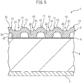
- the top sheet 2 is therefore a sheet having an essentially wavy cross-section with alternately repeating concavo-convexities with respect to the widthwise direction.
- the raised sections 11 are extended in the lengthwise direction of the sanitary napkin 1, i.e. in the lengthwise direction of the top sheet 2, while being arranged in rows with predetermined intervals in the widthwise direction of the top sheet 2.
- each of the raised sections 11 is extended continuously in the lengthwise direction, so as to be mutually parallel with the other raised sections 11.
- the raised section according to the present invention has the interval with the other adjacent raised section of preferably 0.25 to 5 mm, more preferably 0.5 to 3 mm and even more preferably 0.75 to 2 mm.
- the interval between adjacent raised sections is the distance between approximately the center locations of the respective raised sections in the widthwise direction of the top sheet (essentially the top sections of the raised sections).
- the nonwoven fabric cannot be considered to have formed a concavo-convex structure and the contact area with the skin cannot be significantly reduced by the raised sections, and therefore the feel on the skin may potentially be impaired, while conversely if it is greater than 5 mm, the difference with the nonwoven fabric to be processed will not be sufficiently large, making it impossible to obtain a soft feel on the skin using the concavo-convexities.
- the distance between the portion of the second surface 2b at the top section 13 of the raised section 11 and the top sheet side portion of the absorbent body 4 is smaller than the distance between the portion of the first surface 2a of the first bottom section 22 nearest the absorbent body 4 and the top sheet side portion of the absorbent body 4. This is therefore a mode in which the top sections 13 of the raised sections 11 are disposed, overall, at locations more distant from the absorbent body 4 (the upper side in Fig. 4 ) than the first surfaces 2a of the first bottom sections 22.
- the first recess sections 21 are formed integrally with the raised sections 11 in the widthwise direction. Moreover, the thickness at the largest portion of the first bottom section 22 of the first recess section 21 is thickest in the top sheet 2, while the first bottom section 22 is a section with excellent elasticity.
- the plurality of first recess sections 21 formed in the top sheet 2 are all formed with mutually equal widths.
- the second surfaces 2b of the first bottom sections 22 of the first recess sections 21 are joined to the top sheet side portions of the absorbent body 4, at least at the portions of the first bottom sections 22 located furthest to the top sheet side, i.e. the portions located at a depth most distant from the locations of the heights of the top sections 13 of the raised sections 11, and their proximal portions.
- the second recess section 26 has an essentially rectangular opening as viewed flat (as viewed from the first surface 2a of the top sheet 2), and protrudes overall to the absorbent body 4 side of the top sheet 2, defining an essentially cuboid interior space. Also, the second recess sections 26 are disposed at a constant interval in the lengthwise direction of each furrow section 12, more specifically the lengthwise direction of each first recess section 21, and each second recess section 26 is formed in a mutually independent manner from the other second recess sections 26.
- the perimeter wall section 27 has a pair of first perimeter wall sections 29, 29 formed along the lengthwise direction of the top sheet 2 and a pair of second perimeter wall sections 30, 30 formed along the widthwise direction of the top sheet 2.
- the pair of first perimeter wall sections 29, 29 are disposed at mutually facing locations, while the pair of second perimeter wall sections 30, 30 are also disposed at mutually facing locations.
- the pair of first perimeter wall sections 29, 29 have hole sections 31 formed in them passing through from the interior space of the first recess section 21 toward the second surfaces 2b.
- one hole section 31 is provided for each of the pair of first perimeter wall sections 29, 29, and the hole section 31 is formed at a location near the second bottom section 28 of the first perimeter wall section 29 (and therefore two hole sections 31 are present for each second recess section 26).
- the pair of second perimeter wall sections 30, 30 do not have corresponding hole sections 31, and each second perimeter wall section 30 has its entire edge on the absorbent body 4 side directly connected to the second bottom section 28.
- the second recess sections 26 are provided in the top sheet 2 in order to reduce to a minimum the likelihood that the bottoms of the furrow sections 12, and more specifically the first bottom sections 22 of the first recess sections 21, will contact the skin, and in order to minimize the contact area even when the first bottom sections 22 have contacted with the skin.
- the skin is most easily contacted by the raised sections of the top sheet and then by the first bottom sections of the first recess sections, but since the raised sections (especially the top sections) not joined to the absorbent body have the highest degree of softness, it is preferred for the raised sections to be given more opportunity to contact with the skin than the first bottom sections, and the top sheet with less contact area touching with the skin tends to feel softer. Consequently, by providing second recess sections in order to form portions without first recess sections, there will be still fewer portions in contact with the skin at the first bottom sections of the first recess sections, and the opportunity for and contact area of skin contact will be maximally reduced.
- the second recess sections are provided at the first bottom section in order to provide second recess sections in the first bottom section of the first recess section which are less likely to contact the skin than the raised sections, so that the likelihood of the second recess sections contacting the skin will be absolutely minimized and any uncomfortable feeling or sensation of foreign matter caused by the second recess sections will be as little noticeable as possible.
- One reason for providing the hole sections 31 on the first perimeter wall sections 29 for this embodiment is in order to release the tensile force of the fibers of the raised sections 11 adjacent to the furrow section 12 provided with the hole sections 31, thus increasing the freedom of movement of the raised sections 11 as a whole section or of the fibers forming the raised sections 11, and to improve the softness of the raised sections 11, more specifically the softness of the raised sections 11 in the thickness direction of the top sheet 2, as well as the softness when the skin is slid in the lengthwise direction or widthwise direction (especially the widthwise direction) of the top sheet 2, to ensure a smooth feel.
- hole sections 31 are not provided on the second perimeter wall sections 30 so that the level differences, created by the presence of the second recess section 26, will be less likely to catch on the skin when the skin is slid in the lengthwise direction of the top sheet 2, i.e. in the direction in which the raised sections 11 or furrow section 12 are extended, to ensure smoothness in the lengthwise direction of the top sheet 2. That is, since the second perimeter wall sections are continuous with the first bottom sections 22 and second bottom sections 28 and integral without seams, the skin does not significantly sense the level difference of the first bottom sections 22 in the second recess sections 26 and smoothly and easily moves along the raised section 11 and furrow section 12, when the skin is slid in the lengthwise direction of the top sheet 2. This can ensure smoothness in the lengthwise direction of the top sheet 2 due to the softness of the raised sections 11 or softness of the fibers.
- the hole sections 31 are provided at locations of the first perimeter wall sections 29 near the second bottom section 28 in order for the hole sections 31 to be as far as possible from the raised section 11 or first bottom sections 22 that tend to contact the skin, thereby minimizing opportunity for the hole sections 31 to contact the skin and reducing any uncomfortable feeling or sensation of foreign matter. This can more stably ensure smoothness when the skin has been slid in the planar direction of the nonwoven fabric.
- the hole sections 31 are formed by breaking the thermoplastic resin fibers contained in the top sheet 2 and not by melting of the thermoplastic resin fibers, and the perimeters of the hole sections 31 include, among the thermoplastic resin fibers, the broken ends of broken fibers having broken ends formed by breaking of the thermoplastic resin fibers.
- the broken ends of the broken fibers are formed by breaking, accomplished by pulling or physical cutting in the lengthwise direction of the thermoplastic resin fibers, and instead of being melted and rounded fiber ends with increased fiber diameters, as when thermoplastic resin fibers have melted, they are in a tapered state formed by tearing, or else have virtually no change in fiber diameter.
- thermoplastic resin fibers hardened by melting reduces any uncomfortable feeling due to stiffness or catching of the fibers and minimizes any feeling of hardness or roughness from the top sheet 2.
- thermoplastic resin fibers span across the interior spaces of the hole sections 31. Also, some of the broken fibers have their broken ends extending into the interior spaces of the hole sections 31.
- the interior space of the hole section 31 has a combination of thermoplastic resin fibers spanning across the interior space and thermoplastic resin fibers extending into the interior spaces, so that the space are not completely open.
- the thermoplastic resin fibers in the interior spaces can reduce the level differences between the first perimeter wall sections 29 or the second bottom sections 28 of the second recess sections 26, and the hole sections 31, to minimize any difference in touch sensation and to reduce any uncomfortable feeling for the person contacted.
- the open area percentage of the interior space of the hole section is preferably 1 to 50%, more preferably 1.5 to 35% and even more preferably 2.5 to 20%.
- the open area percentage of the interior space of the hole section is less than 1%, the open area percentage will be too low, making it impossible to impart freedom to the raised sections or the fibers of the raised sections, or to adequately ensure softness for the raised sections. If it is 50% or greater, conversely, the strength of the first perimeter wall sections in which the hole sections are formed will tend to be reduced, and the borders of the perimeters of the hole sections may potentially be felt. However, the open area percentage of the interior space of the hole section may be outside of this range, and set as desired, depending on the type of absorbent article and its purpose of use, etc.
- the second bottom sections 28 are formed by the fibers composing the top sheet 2 being compressed in the direction from the first surfaces 2a toward the second surfaces 2b, and have the highest fiber density of the top sheet 2, as mentioned above, as well as the highest rigidity.
- the first surfaces 2a of the second bottom sections 28 i.e. the interior side surfaces of the second recess sections
- the second surfaces 2b i.e. the absorbent body 4 side surfaces
- the sides of the second surfaces 2b of the second bottom sections 28 are essentially flat, and are in contact with the top sheet side surface of the absorbent body 4.
- the second surfaces 2b of the second bottom sections 28 are thus flat, it is possible to maximally increase the contact area between the second bottom sections 28 and the absorbent body 4, thereby making it possible to ensure that the joining regions are as large as possible between the second surfaces 2b of the second bottom sections 28 and the top sheet side surface of the absorbent body 4. As a result, the top sheet 2 is even less likely to detach from the absorbent body 4, and migration of excreted fluids between the top sheet 2 and the absorbent body 4 can proceed more smoothly.
- the top sheet side surface of the absorbent body 4 is a flat surface
- the sides of the second surfaces 2b of the second bottom sections 28 are mutually joined with their surfaces in contact with the top sheet side surface of the absorbent body 4.
- the second recess sections 26 are disposed in a zigzag fashion on the top sheet 2 as viewed flat (as viewed in the thickness direction).
- the top sheet 2 has a structure in which at least two raised sections 11 are situated between a second recess section 26 and another second recess section 26 adjacent to the second recess section 26 in the widthwise direction. That is, the top sheet 2 has a structure with a raised section 11, first recess section 21 and raised section 11 disposed in that order, between a second recess section 26 and its adjacent second recess section 26 in the widthwise direction.
- the top sheet 2 is structured in this manner in order to more stably minimize detachment of the top sheet 2 from the absorbent body 4, and to maintain the softness of the raised sections.
- top sheet 2 has the second recess sections 26 joined to the absorbent body 4
- tensile force can potentially be generated in the widthwise direction on the top sheet 2 due to joining of the second recess sections 26 with the absorbent body.
- first bottom sections 22 which have lower fiber density than the second bottom sections 28 and are more easily deformable than the second bottom sections 28 are situated between adjacent second bottom sections 28, 28, it is possible to absorb the tension by deformation of the first bottom sections 22. This allows the softness of the raised sections 11 to be stably maintained without interfering with freedom of the raised sections 11 in the widthwise direction.
- the external force can be absorbed by deformation of the first bottom sections 22, and therefore the action of large force to the second bottom sections 28 by the external force is reduced and detachment of the second bottom sections 28 from the absorbent body 4 is inhibited, and as a result detachment of the top sheet 2 from the absorbent body 4 is inhibited.
- the structure in which a first recess section 21 of the furrow section 12 and a first recess section 21 of other furrow section 12 adjacent to that furrow section 12 are mutually adjacent has a portion that is continuous over the entire width in the widthwise direction. That is, the top sheet 2 has a structure with a first recess section 21, raised section 11 and first recess section 21 disposed in that order across the entire width in the widthwise direction, and a portion where a second recess section 26 is not present.
- the second recess sections 26 are disposed in a zigzag fashion while the intervals between the second recess sections 26 in the lengthwise direction are set wider than the sizes of the second recess sections 26 in the lengthwise direction.
- first recess section 21 of the furrow section 12 and the first recess section 21 of other furrow section 12 adjacent to that furrow section 12 are mutually adjacent is made continuous across the entire width in the widthwise direction of the top sheet 2 in this manner, in order to utilize the ease of deformation of the first bottom sections 22 of the first recess sections 21 to impart higher softness to the raised sections.
- the first bottom sections 22 that have lower fiber density than the second bottom sections 28 and deform more easily than the second bottom sections 28 cause the raised sections 11 to follow movement of the wearer, and therefore the raised sections fit more stably onto the skin. Furthermore, since the softness of the first bottom sections 22 is utilized to allow the raised sections 11 to also deform more flexibly, it is possible to ensure even higher softness for the top sheet 2 as a whole section.
- the sanitary napkin 1 of this embodiment includes, on the top sheet side surface, a plurality of compressed grooves 41-43 formed by compressing the top sheet 2 and absorbent body 4 by the emboss process in the thickness direction.
- the sanitary napkin 1 of this embodiment is provided with an annular first compressed groove 41 formed long as a whole section in the lengthwise direction of the sanitary napkin 1, located on the outermost side, and a pair of second compressed grooves 42, 42 extending in the lengthwise direction, located on the inner side of the first compressed groove 41 and located at about the center in the lengthwise direction. It is also provided with a pair of third compressed grooves 43, 43 extending in the widthwise direction, being located on the inner side of the first compressed groove 41 and located near both end sides in the lengthwise direction of the first compressed groove 41.
- the compressed grooves 41-43 are provided in order to create more firm bonding between the top sheet 2 and the absorbent body 4 by compressing of the compressed grooves 41-43. They also serve to increase the fiber density between the top sheet 2 and the absorbent body 4, and to increase uptake of excreted fluids from the top sheet 2 to the absorbent body 4.
- the compressed grooves have the top sheet in a state that is stretched in the direction toward the absorbent body, and therefore if some countermeasure is not taken, tensile force is generated in the top sheet, and especially the raised sections, causing stiffness, while the raised sections deform and tend to have reduced softness. This tendency is especially prominent near the compressed grooves.
- the second recess sections of the furrow sections of the top sheet joined to the absorbent body prevent or alleviate the spread of tensile force generated in the top sheet by compressing of the compressed grooves, thus reducing the effect of the tensile force on the raised sections or first recess sections.
- the perimeter wall sections of the second recess sections deform while the second bottom sections are joined to the absorbent body, thereby buffering the tensile force and preventing its spread to other portions or alleviating the tension to prevent its spread to other portions.
- the present invention therefore, it is possible to minimize reduction in softness of the top sheet by the effects of the compressed grooves while more firmly joining the top sheet and the absorbent body by the compressed grooves, and to also reduce to a minimum any collapse of the raised sections or first recess sections due to the tensile force of compressing, and maintain a satisfactory feel on the skin for the top sheet. Furthermore, since collapse of the shapes of the raised sections and first recess sections is reduced, it is possible to minimize the opportunity for contact of the second recess sections with the skin, and in this regard as well, reduction in feel on the skin is minimized.
- the structure is such that the perimeter wall section 27 is cut out by the hole sections 31 formed in the perimeter wall section 27 of the second recess section 26 in the furrow section 12 of the top sheet 2, and therefore the perimeter wall section 27 as a whole section is flexible and deformable, and tensile force acting on the top sheet 2 can be easily buffered. Furthermore, since the hole sections 31 release the tensile force of fibers of the furrow section 12 and their adjacent raised sections 11 and improve the freedom of movement of the raised sections 11 as a whole section or the fibers forming the raised sections 11, as mentioned above, it is easy to alleviate tensile force acting on the top sheet 2. This makes it possible to effectively prevent tensile force generated in the lengthwise direction or widthwise direction of the top sheet 2 by compressing of the compressed grooves, from spreading to other portions. The effect of the tensile force can therefore be even more stably inhibited.
- a plurality of dotted compressed sections 44 are formed by compressing the top sheet 2 and the absorbent body 4, at portions surrounded by second compressed grooves 42, 42 and third compressed grooves 43, 43 on the top sheet side of the sanitary napkin 1, i.e. at essentially the center of the top sheet 2. Similar to the compressed grooves 41-43, these compressed sections 44 can also create tensile force in the top sheet 2 by compressing, but as mentioned above, the effect of the tensile force created by compressing can be reduced by the function of the second recess sections 26.
- the thickness of the compressed sections of the compressed grooves 41-43 or compressed sections 44 will depend on the thickness of the top sheet or the absorbent body, but for example, the thickness of the compressed sections is preferably less than 20%, more preferably no greater than 5% and even more preferably no greater than 3% of the thickness of the absorbent body.
- each of the compressed grooves 41-43 and compressed sections 44 may be the same depth, or mutually different depths.
- a step of forming an absorbent body there are carried out in order a step of forming an absorbent body, a step of laminating a continuous top sheet, formed in a step of forming a long continuous top sheet to be a top sheet as described below, on the absorbent body to form a lamination body of the continuous top sheet and the absorbent body, and a step of forming compressed grooves in the lamination body.
- a production apparatus 50 such as shown in Fig. 7 to Fig. 10 , for example, is used for producing the sanitary napkin 1.
- the production apparatus 50 includes an absorbent body-forming apparatus 60 provided with a freely rotating suction drum 62 that forms an absorbent body 4 by lamination of an absorbent body material 61, a top sheet-forming apparatus 70 that forms a continuous top sheet 71 that is to serve as the top sheet 2, and an embossing apparatus 80 that compresses the top sheet 2 and absorbent body 4 by embossing to form stamped grooves 41-43. It further includes a back sheet roll 90 on which the continuous back sheet 91 that is to be the back sheet 3 is wound as a roll, and a cutting apparatus 100 that cuts the continuous sanitary napkin 92, in which the continuous top sheet 71 and continuous back sheet 91 are attached to the absorbent body 4, to form individual sanitary napkins 1.
- the absorbent body material 61 is supplied from above onto the outer peripheral surface of the rotating suction drum 62, drawing the absorbent body material 61 into a depression-molding member 62a that is provided on the outer peripheral surface of the suction drum 62 and matches the shape of the absorbent body 4, and the absorbent body material 61 is laminated to form an absorbent body 4.
- the rotating suction drum 62 transfers and mounts the absorbent body 4 in the molding member 62a onto a carrier sheet 65 being conveyed in the machine direction MD under the suction drum 62.
- the carrier sheet 65 is conveyed downstream in the machine direction MD together with the mounted absorbent body 4, and is supplied to the following step.
- the step of producing the absorbent body is followed by a step of forming a lamination body.
- the top sheet-forming apparatus 70 described below is used to form a continuous top sheet 71 with the top sheet 2 being continuous in the lengthwise direction. Also, the continuous top sheet 71 is laminated onto the first surface (onto the upper surface in Fig. 7 ) of the absorbent body 4 that is being conveyed in the machine direction MD and joined via an adhesive layer including a hot-melt adhesive, to produce a lamination body 72.
- the lamination body 72 once formed, is conveyed downstream in the machine direction MD and supplied to the following step.
- the step of forming the lamination body is followed by a step of forming compressed grooves.
- the lamination body 72 is passed between an upper roll 81 and a lower roll 82 in the embossing apparatus 80 to compress the continuous top sheet 71 and absorbent body 4 to form compressed grooves 41-43.
- the upper roll 81 of the embossing apparatus 80 includes protrusions (not shown) disposed on the outer peripheral surface and matching the positions and shapes of the compressed grooves 41-43, the protrusions compressing the lamination body 72 from the continuous top sheet 71 side in the thickness direction to form compressed grooves 41-43.
- the lower roll 82 is a roll having a flat outer peripheral surface, and it stably supports the lamination body 72 during compressing of the lamination body 72 by the upper roll 81.
- the upper roll 81 includes protrusions for formation of the compressed sections 44, which are formed simultaneously with the compressed grooves 41-43.
- the step of forming the compressed grooves is followed by a step of forming a continuous sanitary napkin.
- the continuous back sheet 91 that has been reeled out from the back sheet roll 90 is successively laminated onto the absorbent body 4 side surface of the lamination body 72 (onto the lower surface of the lamination body 72 in this case) via an adhesive layer including a hot-melt adhesive, to form a continuous sanitary napkin 92 in which a plurality of sanitary napkins 1 are directly connected in the lengthwise direction.
- the continuous top sheet 71 becomes joined to the first surface of the absorbent body 4 while the continuous back sheet 92 becomes bonded to the surface on the side opposite the first surface (the lower side of the absorbent body 4 in this case).
- the continuous sanitary napkin 92 is conveyed downstream in the machine direction MD and supplied to the next step.
- the step of forming the continuous sanitary napkin is followed by a cutting step.
- the cutter of the cutting apparatus 100 is used to cut out individual sanitary napkins of the desired shapes and sizes from the continuous sanitary napkin.
- the step of forming the continuous top sheet, included in the step of forming the lamination body is carried out in the following manner.
- a preheating step in which, from a top sheet roll 74 around which a long nonwoven fabric 73 to be processed serving as the starting material for the continuous top sheet 71 is wrapped as a roll, the nonwoven fabric 73 to be processed is unrolled, and the nonwoven fabric 73 to be processed that has been unrolled is preheated, and a shaping step in which the nonwoven fabric 73 to be processed that has passed through the preheating step is stretched and shaped.
- the method of producing the continuous top sheet is carried out using the top sheet-forming apparatus 70 as illustrated in Fig. 7 to Fig. 10 .
- the forming apparatus 70 includes the aforementioned top sheet roll 74 that rolls out the nonwoven fabric 73 to be processed downstream in the machine direction MD, a preheating apparatus 76 that applies preheating to the nonwoven fabric 73 to be processed that has been formed by rolling out from the top sheet roll 74, and a shaping apparatus 77 that stretches the nonwoven fabric 73 to be processed that has been preheated, for shaping to form the raised sections 11 and furrow sections 12 (including the first recess sections 21 and second recess sections 26) .
- the continuous top sheet 71 formed in the step of forming a continuous top sheet as shown in Fig. 11 has basically the same structure as the top sheet 2, other than being long in the lengthwise direction, and therefore the same reference signs are used as for the top sheet 2, and will not be explained in detail.
- the long nonwoven fabric 73 to be processed that has been rolled out from the top sheet roll 74 and conveyed along the machine direction MD, is successively contacted with the outer peripheral surfaces of a pair of rotating upper and lower heated rolls 76a, 76b of the preheating apparatus 76, to successively heat both sides of the nonwoven fabric 73 to be processed, thereby applying preheating. That is, the nonwoven fabric 73 to be processed that has been rolled out from the top sheet roll 74 is first taken up onto the outer peripheral surface of the lower heated roll 76b and one surface of the nonwoven fabric 73 to be processed in contact with the outer peripheral surface is heated.
- the nonwoven fabric 73 to be processed is delivered so that the other surface opposite the surface heated by the lower heated roll 76b is contacted with the outer peripheral surface of the upper heated roll 76a, and the surface in contact with the outer peripheral surface is heated by the upper heated roll 76a.
- the preheating temperature will depend on the type of thermoplastic resin fibers composing the nonwoven fabric to be processed, and for example, heating is preferably at above the temperature of initial melting of the thermoplastic resin fibers used in the nonwoven fabric to be processed, and a temperature below the melting point.
- thermoplastic resin fibers will melt and harden, thus impairing the soft feel on the skin. Also if it is below the temperature of initial melting of the thermoplastic resin fibers, joining between the thermoplastic resin fibers will be maintained, making it difficult to shape the nonwoven fabric to be processed in the subsequent shaping step, and making it difficult to form suitable concavo-convexities.
- the nonwoven fabric to be processed is made of core-sheath composite fibers including polyethylene terephthalate (PET) and high-density polyethylene (HDPE), the melting point temperature is 120°C and the initial melting temperature is 50°C or higher, and therefore the temperature of the outer peripheral surfaces of the heated roll is preferably about 50 to 110°C and more preferably about 60 to 100°C.
- PET polyethylene terephthalate
- HDPE high-density polyethylene
- the nonwoven fabric 73 to be processed is inserted between the interlocking and rotating pair of upper and lower stretching rolls 78, 79 of the shaping apparatus 77, stretching the nonwoven fabric 73 to be processed between the ridges 78a and grooves 78b of the upper stretching roll 78 and the recesses 79b and pins 79a of the lower stretching roll 79 which are interlocking, to shape it.
- the heating temperature during this time is preferably higher than the preheating temperature during the preheating step, and a lower temperature than the melting point of the nonwoven fabric 73 to be processed.
- the upper stretching roll 78 includes, on the outer peripheral surface at fixed intervals in the widthwise direction of the roll, the aforementioned rows of ridges 78a formed in mutually parallel along the outer peripheral surface of the upper stretching roll 78, and the aforementioned rows of grooves 78b formed between adjacent ridges 78a, 78a.
- the lower stretching roll 79 includes, on its outer peripheral surface, a plurality of pins 79a provided so as to interlock with the grooves 78b of the upper stretching roll 78, and recesses 79b that interlock with its ridges 78a.
- the pins 79a are disposed at a constant interval in the widthwise direction of the roll so as not to contact the ridges 78a of the upper stretching roll 78 (the interval by which the portions where the pins 79a are not present across the full width of the lower stretching roll 79 in this embodiment), while being linearly disposed at approximately constant interval along the outer peripheral surface, with respect to the circumferential direction of the roll.
- the lower stretching roll 79 of this embodiment has a structure in which a plurality of pins 79a are disposed in a zigzag fashion around the outer peripheral surface of the lower stretching roll 79.
- the upper stretching roll 78 pushes the portions where the ridges 78a contact with the nonwoven fabric 73 to be processed, into the recesses 79b of the lower stretching roll 79, thereby shaping the raised sections 11 of the top sheet 2 (which is the continuous top sheet 71 at this stage).
- the lower stretching roll 79 forces its plurality of pins 79a aligned in rows in the circumferential direction, into the nonwoven fabric 73 to be processed contacting at the tip sections of the pins 79a, at the corresponding grooves 78b of the upper stretching roll 78.
- the portions of the nonwoven fabric 73 to be processed that have been pulled into the grooves 78b without being in contact with the pins 79a are minimally stretched compared to the other portions, and become the first bottom sections 22 of the first recess sections 21 of the furrow sections 12 of the top sheet 2 (continuous top sheet 71).
- the portions that were in contact with the tip sections of the pins 79a are strongly forced into the grooves 78b and shaped, thereby forming second recess sections 26 of the top sheet 2 (continuous top sheet 71) including perimeter wall sections 27 and second bottom sections 28.
- the tip sections of the pins 79a push the contacting portions of the nonwoven fabric 73 to be processed into the grooves 78b while the upper stretching roll 78 and lower stretching roll 79 are meshed with the nonwoven fabric 73 to be processed at the second bottom sections 28 of the second recess sections 26, and therefore the fiber density is essentially higher than at the other portions and the rigidity is increased.
- the top sheet 2 continuous top sheet 71 results in improved rigidity for the nonwoven fabric 73 as a whole section, by the action of the bottom sections 28 of the recess sections 26.
- portions are present where no pins 79a are present across the entire roll width of the lower stretching roll 79, portions are formed in the continuous top sheet 71 where no second recess sections 26 are formed across the entire width (see top sheet 2 in Fig. 5 ).
- the pins 79a shove aside the thermoplastic resin fibers forming the first perimeter wall sections 29 among the perimeter wall sections of the second recess sections, or they break the fibers to form the aforementioned broken fibers with broken ends.
- thermoplastic resin fibers remain in a state spanning across the interior spaces of the hole sections 31, with some of the broken ends of the broken fibers extending into the interior spaces of the hole sections 31.
- the hole sections 31 are formed in the direction of the nonwoven fabric 73 to be processed that is along the machine direction MD, i.e. the rotational direction of the stretching rolls 78, 79, which is the direction in which the raised sections 11 and the furrow sections 12 are extended, the hole sections 31 are also formed on the first perimeter wall sections 29 which are the peripheral surfaces, along the direction in which the raised sections 11 and the furrow sections 12 are extended.
- the raised sections 11 that are not joined to the absorbent body 4 can move freely, and the softness upon contacting the skin is not impaired.
- the second recess sections 26 of the furrow sections 12 are joined to the absorbent body at the second bottom sections 28 that have the highest fiber density in the top sheet 2, it is possible to stably join the top sheet 2 to the absorbent body 4, to stably reduce detachment of the top sheet 2 from the absorbent body 4, and to minimize impairment of the fluid absorption property.
- portions of the first bottom sections 22 are joined to the top sheet side portion of the absorbent body 4, but the first bottom sections do not necessarily need to be joined to the absorbent body 4 so long as the top sheet and the absorbent body are stably joined. In this case as well, the second bottom sections must be reliably joined to the top sheet side of the absorbent body.
- the distance between the portions of the second surfaces 2b at the top sections 13 of the raised sections 11 and the top sheet side portion of the absorbent body 4 is smaller than the distance between the portions of the first surfaces 2a of the first bottom sections 22 nearest the absorbent body 4 and the top sheet side portion of the absorbent body 4.
- the relationship between the distance between the portions of the second surfaces 2b at the top sections of the raised sections and the top sheet side portions of the absorbent body, and the distance between the portions of the first surfaces of the first bottom sections nearest the absorbent body and the top sheet side portions of the absorbent body does not necessarily need to be such a relationship.
- the top sheet 2 has a structure in which at least two raised sections 11 are situated between a second recess section 26 and other second recess section 26 adjacent to that second recess section 26 in the widthwise direction.
- the number of raised sections between the second recess sections may be set as desired.
- the structure in which a first recess section 21 of a furrow section 12 and a first recess section 21 of other furrow section adjacent to that furrow section 12 are mutually adjacent is a structure having a portion that is continuous over the entire width in the widthwise direction.
- the top sheet does not necessarily need to have such a structure.
- the perimeter wall section 27 has a pair of first perimeter wall sections 29, 29 formed along the lengthwise direction, and a pair of second perimeter wall sections 30, 30 formed along the widthwise direction, and hole sections 31 passing through to the second surface 2b are formed in the pair of first perimeter wall sections 29, 29.
- the second surfaces of the second bottom sections are formed flat, but so long as it is possible to adequately ensure the softness of the second surfaces of the second bottom sections, the second surfaces do not necessarily need to be flat.
- the absorbent article (sanitary napkin 1) of the embodiment described above includes, on the top sheet side surface, compressed sections 44 extending in the widthwise direction where the top sheet 2 and absorbent body 4 have been compressed in the thickness direction, but such compressed sections do not necessarily need to be provided.
- the absorbent article may be any type of absorbent article such as a disposable diaper, incontinence pad (panty liner) or the like.
Applications Claiming Priority (2)
| Application Number | Priority Date | Filing Date | Title |
|---|---|---|---|
| JP2015104888A JP6038228B1 (ja) | 2015-05-22 | 2015-05-22 | 吸収性物品 |
| PCT/JP2016/056116 WO2016189914A1 (ja) | 2015-05-22 | 2016-02-29 | 吸収性物品 |
Publications (3)
| Publication Number | Publication Date |
|---|---|
| EP3298997A1 EP3298997A1 (en) | 2018-03-28 |
| EP3298997A4 EP3298997A4 (en) | 2018-04-25 |
| EP3298997B1 true EP3298997B1 (en) | 2019-01-02 |
Family
ID=57393137
Family Applications (1)
| Application Number | Title | Priority Date | Filing Date |
|---|---|---|---|
| EP16799623.0A Active EP3298997B1 (en) | 2015-05-22 | 2016-02-29 | Absorbent article |
Country Status (8)
| Country | Link |
|---|---|
| US (1) | US10786400B2 (ko) |
| EP (1) | EP3298997B1 (ko) |
| JP (1) | JP6038228B1 (ko) |
| KR (1) | KR20180011077A (ko) |
| CN (1) | CN107613931B (ko) |
| BR (1) | BR112017024549A2 (ko) |
| MY (1) | MY180453A (ko) |
| WO (1) | WO2016189914A1 (ko) |
Families Citing this family (7)
| Publication number | Priority date | Publication date | Assignee | Title |
|---|---|---|---|---|
| JP6805818B2 (ja) * | 2016-12-28 | 2020-12-23 | 王子ホールディングス株式会社 | 吸収性物品の製造方法及び製造装置 |
| US11168420B2 (en) | 2017-08-31 | 2021-11-09 | Kao Corporation | Nonwoven fabric |
| IT201800002181A1 (it) * | 2018-01-30 | 2019-07-30 | Gdm Spa | Apparato e metodo di formatura di una imbottitura assorbente |
| JP2020049084A (ja) * | 2018-09-28 | 2020-04-02 | 花王株式会社 | 吸収性物品 |
| CN113905698A (zh) * | 2019-05-15 | 2022-01-07 | 宝洁公司 | 一次性吸收制品 |
| WO2021151238A1 (en) * | 2020-01-31 | 2021-08-05 | The Procter & Gamble Company | Apertured nonwoven web and method of forming thereof |
| WO2024057968A1 (ja) * | 2022-09-16 | 2024-03-21 | 株式会社瑞光 | 吸収性シート |
Family Cites Families (15)
| Publication number | Priority date | Publication date | Assignee | Title |
|---|---|---|---|---|
| JP2809491B2 (ja) * | 1990-06-26 | 1998-10-08 | ユニ・チャーム株式会社 | 吸収性物品の表面シート |
| JP3348871B2 (ja) * | 1992-05-14 | 2002-11-20 | 花王株式会社 | 吸収性物品の表面材 |
| JP3061507B2 (ja) * | 1993-03-24 | 2000-07-10 | 三井化学株式会社 | 体液吸収性物品の表面シート、その製造方法、およびその製造装置 |
| JP3611666B2 (ja) | 1996-05-13 | 2005-01-19 | 花王株式会社 | 吸収性物品 |
| JPH10211232A (ja) | 1997-01-31 | 1998-08-11 | Uni Charm Corp | 使い捨て体液吸収性着用物品の表面シートおよびその製造方法 |
| JP3748743B2 (ja) | 1999-10-04 | 2006-02-22 | ユニ・チャーム株式会社 | 吸収性物品およびその製造方法 |
| US7550646B2 (en) | 2002-09-09 | 2009-06-23 | Uni-Charm Corporation | Absorbent article with resilient portion and method for manufacturing the same |
| US7468114B2 (en) * | 2002-11-13 | 2008-12-23 | Kao Corporation | Composite sheet and process and apparatus for producing the same |
| CN101065085B (zh) * | 2004-11-30 | 2011-03-16 | 宝洁公司 | 具有一对后侧翼的吸收制品 |
| JP4540590B2 (ja) * | 2005-11-09 | 2010-09-08 | 花王株式会社 | 吸収性物品用の立体シート |
| JP5441356B2 (ja) * | 2008-05-15 | 2014-03-12 | ユニ・チャーム株式会社 | 吸収性物品用表面シートとその製造方法およびそれを用いた吸収性物品 |
| JP5455363B2 (ja) | 2008-12-25 | 2014-03-26 | ユニ・チャーム株式会社 | 薄型吸収性物品 |
| JP5374345B2 (ja) * | 2009-12-09 | 2013-12-25 | 花王株式会社 | 生理用ナプキン |
| CA2871680C (en) * | 2012-04-25 | 2018-01-09 | The Procter & Gamble Company | Corrugated and apertured web |
| JP6189143B2 (ja) * | 2012-10-31 | 2017-08-30 | 花王株式会社 | 吸収性物品 |
-
2015
- 2015-05-22 JP JP2015104888A patent/JP6038228B1/ja active Active
-
2016
- 2016-02-29 MY MYPI2017704009A patent/MY180453A/en unknown
- 2016-02-29 BR BR112017024549A patent/BR112017024549A2/pt active Search and Examination
- 2016-02-29 WO PCT/JP2016/056116 patent/WO2016189914A1/ja active Application Filing
- 2016-02-29 US US15/574,183 patent/US10786400B2/en active Active
- 2016-02-29 KR KR1020177031733A patent/KR20180011077A/ko unknown
- 2016-02-29 EP EP16799623.0A patent/EP3298997B1/en active Active
- 2016-02-29 CN CN201680029811.1A patent/CN107613931B/zh active Active
Non-Patent Citations (1)
| Title |
|---|
| None * |
Also Published As
| Publication number | Publication date |
|---|---|
| EP3298997A4 (en) | 2018-04-25 |
| WO2016189914A1 (ja) | 2016-12-01 |
| JP2016214688A (ja) | 2016-12-22 |
| CN107613931B (zh) | 2020-12-18 |
| EP3298997A1 (en) | 2018-03-28 |
| MY180453A (en) | 2020-11-29 |
| BR112017024549A2 (pt) | 2018-07-24 |
| KR20180011077A (ko) | 2018-01-31 |
| US20180098895A1 (en) | 2018-04-12 |
| US10786400B2 (en) | 2020-09-29 |
| CN107613931A (zh) | 2018-01-19 |
| JP6038228B1 (ja) | 2016-12-07 |
Similar Documents
| Publication | Publication Date | Title |
|---|---|---|
| EP3298997B1 (en) | Absorbent article | |
| EP3254653B1 (en) | Absorbent article | |
| KR100452238B1 (ko) | 체액 흡수성 물품의 투액성 표면시트, 이의 제조장치 및 제조방법 | |
| JP5165756B2 (ja) | 吸収性物品 | |
| JP4938129B2 (ja) | 吸収性物品 | |
| EP2478881B1 (en) | Absorptive article | |
| EP2087865A1 (en) | Absorptive article and method of producing the same | |
| EP2223670A1 (en) | Absorbent article and method of producing the same | |
| JP6000412B1 (ja) | 吸収性物品用の賦形された不織布、当該賦形された不織布を含む吸収性物品、及び上記賦形された不織布の製造方法 | |
| JP2006326299A (ja) | 多数のマイクロエンボシングから構成されたマクロエンボシングを備えるよれ及び漏れ防止機能と審美的効果が増大した吸収製品 | |
| JP4204518B2 (ja) | 吸収性物品の表面シート | |
| EP3245991B1 (en) | Non-woven fabric for absorbent article | |
| JP2005296480A (ja) | 生理用ナプキン | |
| JP2006061175A (ja) | 吸収性物品の表面シート | |
| TWI675138B (zh) | 吸收性物品用不織布 | |
| JP4167389B2 (ja) | 吸収性物品およびその製造装置 | |
| JP2016221237A (ja) | 吸収性物品 | |
| JP2006129891A (ja) | 吸収性物品 | |
| JP3998655B2 (ja) | 吸収性物品の表面シート | |
| JP6628696B2 (ja) | 吸収性物品用の賦形された不織布、当該賦形された不織布を含む吸収性物品、及び上記賦形された不織布の製造方法 | |
| JP6257558B2 (ja) | 吸収性物品 |
Legal Events
| Date | Code | Title | Description |
|---|---|---|---|
| STAA | Information on the status of an ep patent application or granted ep patent |
Free format text: STATUS: THE INTERNATIONAL PUBLICATION HAS BEEN MADE |
|
| PUAI | Public reference made under article 153(3) epc to a published international application that has entered the european phase |
Free format text: ORIGINAL CODE: 0009012 |
|
| STAA | Information on the status of an ep patent application or granted ep patent |
Free format text: STATUS: REQUEST FOR EXAMINATION WAS MADE |
|
| 17P | Request for examination filed |
Effective date: 20171025 |
|
| AK | Designated contracting states |
Kind code of ref document: A1 Designated state(s): AL AT BE BG CH CY CZ DE DK EE ES FI FR GB GR HR HU IE IS IT LI LT LU LV MC MK MT NL NO PL PT RO RS SE SI SK SM TR |
|
| AX | Request for extension of the european patent |
Extension state: BA ME |
|
| A4 | Supplementary search report drawn up and despatched |
Effective date: 20180327 |
|
| RIC1 | Information provided on ipc code assigned before grant |
Ipc: A61F 13/511 20060101AFI20180321BHEP |
|
| DAV | Request for validation of the european patent (deleted) | ||
| DAX | Request for extension of the european patent (deleted) | ||
| GRAP | Despatch of communication of intention to grant a patent |
Free format text: ORIGINAL CODE: EPIDOSNIGR1 |
|
| STAA | Information on the status of an ep patent application or granted ep patent |
Free format text: STATUS: GRANT OF PATENT IS INTENDED |
|
| INTG | Intention to grant announced |
Effective date: 20180914 |
|
| GRAS | Grant fee paid |
Free format text: ORIGINAL CODE: EPIDOSNIGR3 |
|
| GRAA | (expected) grant |
Free format text: ORIGINAL CODE: 0009210 |
|
| STAA | Information on the status of an ep patent application or granted ep patent |
Free format text: STATUS: THE PATENT HAS BEEN GRANTED |
|
| AK | Designated contracting states |
Kind code of ref document: B1 Designated state(s): AL AT BE BG CH CY CZ DE DK EE ES FI FR GB GR HR HU IE IS IT LI LT LU LV MC MK MT NL NO PL PT RO RS SE SI SK SM TR |
|
| REG | Reference to a national code |
Ref country code: GB Ref legal event code: FG4D |
|
| REG | Reference to a national code |
Ref country code: CH Ref legal event code: EP Ref country code: AT Ref legal event code: REF Ref document number: 1083453 Country of ref document: AT Kind code of ref document: T Effective date: 20190115 |
|
| REG | Reference to a national code |
Ref country code: IE Ref legal event code: FG4D |
|
| REG | Reference to a national code |
Ref country code: DE Ref legal event code: R096 Ref document number: 602016009054 Country of ref document: DE |
|
| REG | Reference to a national code |
Ref country code: SE Ref legal event code: TRGR |
|
| REG | Reference to a national code |
Ref country code: NL Ref legal event code: FP |
|
| REG | Reference to a national code |
Ref country code: LT Ref legal event code: MG4D |
|
| REG | Reference to a national code |
Ref country code: AT Ref legal event code: MK05 Ref document number: 1083453 Country of ref document: AT Kind code of ref document: T Effective date: 20190102 |
|
| PG25 | Lapsed in a contracting state [announced via postgrant information from national office to epo] |
Ref country code: ES Free format text: LAPSE BECAUSE OF FAILURE TO SUBMIT A TRANSLATION OF THE DESCRIPTION OR TO PAY THE FEE WITHIN THE PRESCRIBED TIME-LIMIT Effective date: 20190102 Ref country code: PT Free format text: LAPSE BECAUSE OF FAILURE TO SUBMIT A TRANSLATION OF THE DESCRIPTION OR TO PAY THE FEE WITHIN THE PRESCRIBED TIME-LIMIT Effective date: 20190502 Ref country code: PL Free format text: LAPSE BECAUSE OF FAILURE TO SUBMIT A TRANSLATION OF THE DESCRIPTION OR TO PAY THE FEE WITHIN THE PRESCRIBED TIME-LIMIT Effective date: 20190102 Ref country code: LT Free format text: LAPSE BECAUSE OF FAILURE TO SUBMIT A TRANSLATION OF THE DESCRIPTION OR TO PAY THE FEE WITHIN THE PRESCRIBED TIME-LIMIT Effective date: 20190102 Ref country code: FI Free format text: LAPSE BECAUSE OF FAILURE TO SUBMIT A TRANSLATION OF THE DESCRIPTION OR TO PAY THE FEE WITHIN THE PRESCRIBED TIME-LIMIT Effective date: 20190102 Ref country code: NO Free format text: LAPSE BECAUSE OF FAILURE TO SUBMIT A TRANSLATION OF THE DESCRIPTION OR TO PAY THE FEE WITHIN THE PRESCRIBED TIME-LIMIT Effective date: 20190402 |
|
| PG25 | Lapsed in a contracting state [announced via postgrant information from national office to epo] |
Ref country code: BG Free format text: LAPSE BECAUSE OF FAILURE TO SUBMIT A TRANSLATION OF THE DESCRIPTION OR TO PAY THE FEE WITHIN THE PRESCRIBED TIME-LIMIT Effective date: 20190402 Ref country code: IS Free format text: LAPSE BECAUSE OF FAILURE TO SUBMIT A TRANSLATION OF THE DESCRIPTION OR TO PAY THE FEE WITHIN THE PRESCRIBED TIME-LIMIT Effective date: 20190502 Ref country code: LV Free format text: LAPSE BECAUSE OF FAILURE TO SUBMIT A TRANSLATION OF THE DESCRIPTION OR TO PAY THE FEE WITHIN THE PRESCRIBED TIME-LIMIT Effective date: 20190102 Ref country code: RS Free format text: LAPSE BECAUSE OF FAILURE TO SUBMIT A TRANSLATION OF THE DESCRIPTION OR TO PAY THE FEE WITHIN THE PRESCRIBED TIME-LIMIT Effective date: 20190102 Ref country code: HR Free format text: LAPSE BECAUSE OF FAILURE TO SUBMIT A TRANSLATION OF THE DESCRIPTION OR TO PAY THE FEE WITHIN THE PRESCRIBED TIME-LIMIT Effective date: 20190102 Ref country code: GR Free format text: LAPSE BECAUSE OF FAILURE TO SUBMIT A TRANSLATION OF THE DESCRIPTION OR TO PAY THE FEE WITHIN THE PRESCRIBED TIME-LIMIT Effective date: 20190403 |
|
| REG | Reference to a national code |
Ref country code: CH Ref legal event code: PL |
|
| REG | Reference to a national code |
Ref country code: DE Ref legal event code: R097 Ref document number: 602016009054 Country of ref document: DE |
|
| PG25 | Lapsed in a contracting state [announced via postgrant information from national office to epo] |
Ref country code: CZ Free format text: LAPSE BECAUSE OF FAILURE TO SUBMIT A TRANSLATION OF THE DESCRIPTION OR TO PAY THE FEE WITHIN THE PRESCRIBED TIME-LIMIT Effective date: 20190102 Ref country code: IT Free format text: LAPSE BECAUSE OF FAILURE TO SUBMIT A TRANSLATION OF THE DESCRIPTION OR TO PAY THE FEE WITHIN THE PRESCRIBED TIME-LIMIT Effective date: 20190102 Ref country code: RO Free format text: LAPSE BECAUSE OF FAILURE TO SUBMIT A TRANSLATION OF THE DESCRIPTION OR TO PAY THE FEE WITHIN THE PRESCRIBED TIME-LIMIT Effective date: 20190102 Ref country code: AL Free format text: LAPSE BECAUSE OF FAILURE TO SUBMIT A TRANSLATION OF THE DESCRIPTION OR TO PAY THE FEE WITHIN THE PRESCRIBED TIME-LIMIT Effective date: 20190102 Ref country code: MC Free format text: LAPSE BECAUSE OF FAILURE TO SUBMIT A TRANSLATION OF THE DESCRIPTION OR TO PAY THE FEE WITHIN THE PRESCRIBED TIME-LIMIT Effective date: 20190102 Ref country code: LU Free format text: LAPSE BECAUSE OF NON-PAYMENT OF DUE FEES Effective date: 20190228 Ref country code: SK Free format text: LAPSE BECAUSE OF FAILURE TO SUBMIT A TRANSLATION OF THE DESCRIPTION OR TO PAY THE FEE WITHIN THE PRESCRIBED TIME-LIMIT Effective date: 20190102 Ref country code: DK Free format text: LAPSE BECAUSE OF FAILURE TO SUBMIT A TRANSLATION OF THE DESCRIPTION OR TO PAY THE FEE WITHIN THE PRESCRIBED TIME-LIMIT Effective date: 20190102 Ref country code: EE Free format text: LAPSE BECAUSE OF FAILURE TO SUBMIT A TRANSLATION OF THE DESCRIPTION OR TO PAY THE FEE WITHIN THE PRESCRIBED TIME-LIMIT Effective date: 20190102 Ref country code: AT Free format text: LAPSE BECAUSE OF FAILURE TO SUBMIT A TRANSLATION OF THE DESCRIPTION OR TO PAY THE FEE WITHIN THE PRESCRIBED TIME-LIMIT Effective date: 20190102 |
|
| PLBE | No opposition filed within time limit |
Free format text: ORIGINAL CODE: 0009261 |
|
| STAA | Information on the status of an ep patent application or granted ep patent |
Free format text: STATUS: NO OPPOSITION FILED WITHIN TIME LIMIT |
|
| REG | Reference to a national code |
Ref country code: BE Ref legal event code: MM Effective date: 20190228 |
|
| REG | Reference to a national code |
Ref country code: IE Ref legal event code: MM4A |
|
| PG25 | Lapsed in a contracting state [announced via postgrant information from national office to epo] |
Ref country code: SM Free format text: LAPSE BECAUSE OF FAILURE TO SUBMIT A TRANSLATION OF THE DESCRIPTION OR TO PAY THE FEE WITHIN THE PRESCRIBED TIME-LIMIT Effective date: 20190102 |
|
| 26N | No opposition filed |
Effective date: 20191003 |
|
| PG25 | Lapsed in a contracting state [announced via postgrant information from national office to epo] |
Ref country code: LI Free format text: LAPSE BECAUSE OF NON-PAYMENT OF DUE FEES Effective date: 20190228 Ref country code: CH Free format text: LAPSE BECAUSE OF NON-PAYMENT OF DUE FEES Effective date: 20190228 |
|
| PG25 | Lapsed in a contracting state [announced via postgrant information from national office to epo] |
Ref country code: IE Free format text: LAPSE BECAUSE OF NON-PAYMENT OF DUE FEES Effective date: 20190228 |
|
| PG25 | Lapsed in a contracting state [announced via postgrant information from national office to epo] |
Ref country code: SI Free format text: LAPSE BECAUSE OF FAILURE TO SUBMIT A TRANSLATION OF THE DESCRIPTION OR TO PAY THE FEE WITHIN THE PRESCRIBED TIME-LIMIT Effective date: 20190102 Ref country code: BE Free format text: LAPSE BECAUSE OF NON-PAYMENT OF DUE FEES Effective date: 20190228 |
|
| PG25 | Lapsed in a contracting state [announced via postgrant information from national office to epo] |
Ref country code: TR Free format text: LAPSE BECAUSE OF FAILURE TO SUBMIT A TRANSLATION OF THE DESCRIPTION OR TO PAY THE FEE WITHIN THE PRESCRIBED TIME-LIMIT Effective date: 20190102 |
|
| PG25 | Lapsed in a contracting state [announced via postgrant information from national office to epo] |
Ref country code: MT Free format text: LAPSE BECAUSE OF NON-PAYMENT OF DUE FEES Effective date: 20190228 |
|
| PG25 | Lapsed in a contracting state [announced via postgrant information from national office to epo] |
Ref country code: CY Free format text: LAPSE BECAUSE OF FAILURE TO SUBMIT A TRANSLATION OF THE DESCRIPTION OR TO PAY THE FEE WITHIN THE PRESCRIBED TIME-LIMIT Effective date: 20190102 |
|
| PG25 | Lapsed in a contracting state [announced via postgrant information from national office to epo] |
Ref country code: HU Free format text: LAPSE BECAUSE OF FAILURE TO SUBMIT A TRANSLATION OF THE DESCRIPTION OR TO PAY THE FEE WITHIN THE PRESCRIBED TIME-LIMIT; INVALID AB INITIO Effective date: 20160229 |
|
| PG25 | Lapsed in a contracting state [announced via postgrant information from national office to epo] |
Ref country code: MK Free format text: LAPSE BECAUSE OF FAILURE TO SUBMIT A TRANSLATION OF THE DESCRIPTION OR TO PAY THE FEE WITHIN THE PRESCRIBED TIME-LIMIT Effective date: 20190102 |
|
| PGFP | Annual fee paid to national office [announced via postgrant information from national office to epo] |
Ref country code: FR Payment date: 20230110 Year of fee payment: 8 |
|
| PGFP | Annual fee paid to national office [announced via postgrant information from national office to epo] |
Ref country code: SE Payment date: 20230110 Year of fee payment: 8 Ref country code: GB Payment date: 20230105 Year of fee payment: 8 Ref country code: DE Payment date: 20221230 Year of fee payment: 8 |
|
| PGFP | Annual fee paid to national office [announced via postgrant information from national office to epo] |
Ref country code: NL Payment date: 20240108 Year of fee payment: 9 |
|
| PGFP | Annual fee paid to national office [announced via postgrant information from national office to epo] |
Ref country code: DE Payment date: 20231229 Year of fee payment: 9 Ref country code: GB Payment date: 20240108 Year of fee payment: 9 |