EP3297184B1 - Transimpedanzverstärker für optische hochgeschwindigkeitskommunikation auf grundlage linearer modulationen - Google Patents
Transimpedanzverstärker für optische hochgeschwindigkeitskommunikation auf grundlage linearer modulationen Download PDFInfo
- Publication number
- EP3297184B1 EP3297184B1 EP16382431.1A EP16382431A EP3297184B1 EP 3297184 B1 EP3297184 B1 EP 3297184B1 EP 16382431 A EP16382431 A EP 16382431A EP 3297184 B1 EP3297184 B1 EP 3297184B1
- Authority
- EP
- European Patent Office
- Prior art keywords
- amplifier circuit
- transimpedance
- transimpedance amplifier
- exemplary
- circuit
- Prior art date
- Legal status (The legal status is an assumption and is not a legal conclusion. Google has not performed a legal analysis and makes no representation as to the accuracy of the status listed.)
- Active
Links
- 230000003287 optical effect Effects 0.000 title claims description 157
- 238000004891 communication Methods 0.000 title claims description 29
- 239000004065 semiconductor Substances 0.000 claims description 10
- 239000003990 capacitor Substances 0.000 claims description 4
- 230000005669 field effect Effects 0.000 claims description 4
- 238000005516 engineering process Methods 0.000 description 12
- 230000004913 activation Effects 0.000 description 11
- 238000001994 activation Methods 0.000 description 11
- 238000000034 method Methods 0.000 description 8
- 239000000872 buffer Substances 0.000 description 7
- 230000004044 response Effects 0.000 description 7
- 230000005540 biological transmission Effects 0.000 description 6
- 230000008569 process Effects 0.000 description 6
- 239000008186 active pharmaceutical agent Substances 0.000 description 5
- 239000000835 fiber Substances 0.000 description 5
- JBRZTFJDHDCESZ-UHFFFAOYSA-N AsGa Chemical compound [As]#[Ga] JBRZTFJDHDCESZ-UHFFFAOYSA-N 0.000 description 4
- 229910001218 Gallium arsenide Inorganic materials 0.000 description 4
- 230000008901 benefit Effects 0.000 description 4
- 238000006243 chemical reaction Methods 0.000 description 4
- 239000013307 optical fiber Substances 0.000 description 4
- 230000007704 transition Effects 0.000 description 4
- 230000000295 complement effect Effects 0.000 description 3
- 230000036039 immunity Effects 0.000 description 3
- 238000004513 sizing Methods 0.000 description 2
- RYGMFSIKBFXOCR-UHFFFAOYSA-N Copper Chemical compound [Cu] RYGMFSIKBFXOCR-UHFFFAOYSA-N 0.000 description 1
- 230000008033 biological extinction Effects 0.000 description 1
- 230000015556 catabolic process Effects 0.000 description 1
- 229910052802 copper Inorganic materials 0.000 description 1
- 239000010949 copper Substances 0.000 description 1
- 238000006731 degradation reaction Methods 0.000 description 1
- 230000001419 dependent effect Effects 0.000 description 1
- 238000011161 development Methods 0.000 description 1
- 230000018109 developmental process Effects 0.000 description 1
- 238000001914 filtration Methods 0.000 description 1
- 238000002347 injection Methods 0.000 description 1
- 239000007924 injection Substances 0.000 description 1
- 230000000630 rising effect Effects 0.000 description 1
- 239000000243 solution Substances 0.000 description 1
- 230000003595 spectral effect Effects 0.000 description 1
- 230000001052 transient effect Effects 0.000 description 1
Images


Classifications
-
- H—ELECTRICITY
- H04—ELECTRIC COMMUNICATION TECHNIQUE
- H04B—TRANSMISSION
- H04B10/00—Transmission systems employing electromagnetic waves other than radio-waves, e.g. infrared, visible or ultraviolet light, or employing corpuscular radiation, e.g. quantum communication
- H04B10/60—Receivers
- H04B10/66—Non-coherent receivers, e.g. using direct detection
- H04B10/69—Electrical arrangements in the receiver
- H04B10/697—Arrangements for reducing noise and distortion
-
- H—ELECTRICITY
- H04—ELECTRIC COMMUNICATION TECHNIQUE
- H04B—TRANSMISSION
- H04B10/00—Transmission systems employing electromagnetic waves other than radio-waves, e.g. infrared, visible or ultraviolet light, or employing corpuscular radiation, e.g. quantum communication
- H04B10/60—Receivers
- H04B10/66—Non-coherent receivers, e.g. using direct detection
- H04B10/69—Electrical arrangements in the receiver
- H04B10/693—Arrangements for optimizing the preamplifier in the receiver
- H04B10/6931—Automatic gain control of the preamplifier
-
- H—ELECTRICITY
- H03—ELECTRONIC CIRCUITRY
- H03F—AMPLIFIERS
- H03F3/00—Amplifiers with only discharge tubes or only semiconductor devices as amplifying elements
- H03F3/04—Amplifiers with only discharge tubes or only semiconductor devices as amplifying elements with semiconductor devices only
- H03F3/08—Amplifiers with only discharge tubes or only semiconductor devices as amplifying elements with semiconductor devices only controlled by light
- H03F3/087—Amplifiers with only discharge tubes or only semiconductor devices as amplifying elements with semiconductor devices only controlled by light with IC amplifier blocks
-
- H—ELECTRICITY
- H03—ELECTRONIC CIRCUITRY
- H03F—AMPLIFIERS
- H03F3/00—Amplifiers with only discharge tubes or only semiconductor devices as amplifying elements
- H03F3/45—Differential amplifiers
- H03F3/45071—Differential amplifiers with semiconductor devices only
- H03F3/45076—Differential amplifiers with semiconductor devices only characterised by the way of implementation of the active amplifying circuit in the differential amplifier
- H03F3/45475—Differential amplifiers with semiconductor devices only characterised by the way of implementation of the active amplifying circuit in the differential amplifier using IC blocks as the active amplifying circuit
-
- H—ELECTRICITY
- H03—ELECTRONIC CIRCUITRY
- H03G—CONTROL OF AMPLIFICATION
- H03G1/00—Details of arrangements for controlling amplification
- H03G1/0005—Circuits characterised by the type of controlling devices operated by a controlling current or voltage signal
- H03G1/0035—Circuits characterised by the type of controlling devices operated by a controlling current or voltage signal using continuously variable impedance elements
-
- H—ELECTRICITY
- H03—ELECTRONIC CIRCUITRY
- H03G—CONTROL OF AMPLIFICATION
- H03G3/00—Gain control in amplifiers or frequency changers without distortion of the input signal
- H03G3/001—Digital control of analog signals
-
- H—ELECTRICITY
- H03—ELECTRONIC CIRCUITRY
- H03G—CONTROL OF AMPLIFICATION
- H03G3/00—Gain control in amplifiers or frequency changers without distortion of the input signal
- H03G3/20—Automatic control
- H03G3/30—Automatic control in amplifiers having semiconductor devices
- H03G3/3084—Automatic control in amplifiers having semiconductor devices in receivers or transmitters for electromagnetic waves other than radiowaves, e.g. lightwaves
-
- H—ELECTRICITY
- H04—ELECTRIC COMMUNICATION TECHNIQUE
- H04B—TRANSMISSION
- H04B10/00—Transmission systems employing electromagnetic waves other than radio-waves, e.g. infrared, visible or ultraviolet light, or employing corpuscular radiation, e.g. quantum communication
- H04B10/60—Receivers
- H04B10/61—Coherent receivers
- H04B10/616—Details of the electronic signal processing in coherent optical receivers
-
- H—ELECTRICITY
- H04—ELECTRIC COMMUNICATION TECHNIQUE
- H04B—TRANSMISSION
- H04B10/00—Transmission systems employing electromagnetic waves other than radio-waves, e.g. infrared, visible or ultraviolet light, or employing corpuscular radiation, e.g. quantum communication
- H04B10/60—Receivers
- H04B10/66—Non-coherent receivers, e.g. using direct detection
- H04B10/69—Electrical arrangements in the receiver
- H04B10/693—Arrangements for optimizing the preamplifier in the receiver
- H04B10/6933—Offset control of the differential preamplifier
-
- H—ELECTRICITY
- H03—ELECTRONIC CIRCUITRY
- H03F—AMPLIFIERS
- H03F2203/00—Indexing scheme relating to amplifiers with only discharge tubes or only semiconductor devices as amplifying elements covered by H03F3/00
- H03F2203/45—Indexing scheme relating to differential amplifiers
- H03F2203/45116—Feedback coupled to the input of the differential amplifier
-
- H—ELECTRICITY
- H03—ELECTRONIC CIRCUITRY
- H03F—AMPLIFIERS
- H03F2203/00—Indexing scheme relating to amplifiers with only discharge tubes or only semiconductor devices as amplifying elements covered by H03F3/00
- H03F2203/45—Indexing scheme relating to differential amplifiers
- H03F2203/45138—Two or more differential amplifiers in IC-block form are combined, e.g. measuring amplifiers
-
- H—ELECTRICITY
- H03—ELECTRONIC CIRCUITRY
- H03F—AMPLIFIERS
- H03F2203/00—Indexing scheme relating to amplifiers with only discharge tubes or only semiconductor devices as amplifying elements covered by H03F3/00
- H03F2203/45—Indexing scheme relating to differential amplifiers
- H03F2203/45288—Differential amplifier with circuit arrangements to enhance the transconductance
Definitions
- the invention relates to an optical receiver circuit of the type as specified in the preamble of patent claim 1 and an optical receiver as specified in the preamble of patent claim 15.
- Optical communication systems are nowadays widely used in home networks and industrial applications, for example, the MOST (Media Oriented Systems Transport) technology used in the automotive industry for high-speed multimedia networks is based on plastic over fiber (POF) technology.
- MOST Media Oriented Systems Transport
- POF plastic over fiber
- a light emitting device the optical transmitter, outputs an optical signal that is fed into an optical fiber link, e.g. a plastic fiber, which guides the optical signal to a light receiving device, the optical receiver, which comprises a photo detector for receiving the optical signal.
- an optical fiber link e.g. a plastic fiber
- the optical receiver which comprises a photo detector for receiving the optical signal.
- optical communication systems inter alia have several advantages compared with the conventional non-optical communication systems over copper: e.g. lower attenuation, immunity to electromagnetic interference irradiation and higher data rate transmission. In recent years optical communication systems are therefore more and more also used for in-vehicle data communication.
- optical communication systems however are inter alia suffering from the challenge that, the optical communication system, in particular the performance of the optical receiver, does not adequately deal with variations in received optical powers that can span several orders of magnitude, resulting in undesired noisy and non-linear behavior of the electric output signal of the optical receiver.
- the performance of the optical receiver can degrade due to, for example, undesired fluctuations in voltage, temperature and/or due to local process variations (also called process variations for brevity), i.e. due to naturally occurring variations in the attributes of electronic components such as transistors when electronic integrated circuits are manufactured.
- Optical receiver circuits according to the state of the art are known from US-A-6844784 , US-A-5606277 and US-A-2006034621 .
- the object of the present invention to provide means for improving an optical communication system.
- the object may comprise improving the performance and reliability of an optical communication system, in particular, improving the performance and reliability of an optical receiver of an optical communication system.
- an optical receiver circuit for use in an optical communication system can comprise one, some or all of the following components:
- An optical receiver circuit for use in an optical receiver of an optical communication system has inter alia the advantage that the linearity of the optical receiver is improved, i.e. in particular the linearity of the conversion of the input current signal, e.g. the photocurrent signal generated by the at least one photo detector, to an output signal, i.e. an output voltage signal, of the optical receiver.
- the implementation of the automatic gain control can avoid the saturation of the transimpedance amplifier circuit output voltage for high input current signals, i.e. high input photocurrents that, for example, can be 3, 4 or more magnitudes larger than the smallest occurring input photocurrents, and can thereby reduce output distortion. For example, if the lowest input photocurrents are 100nA, saturation of the transimpedance amplifier circuit output voltage can be avoided for input photocurrents up to 1mA or higher.
- an optical receiver circuit for use in an exemplary optical receiver according to the present invention can provide a high linearity for said conversion of an input signal, e.g. input current signal, to an output signal, e.g. output voltage signal, for a wide dynamic range of input signals, i.e. for a wide dynamic range of the input current signal.
- an input signal e.g. input current signal
- an output signal e.g. output voltage signal
- the input current signal e.g. the photocurrent signal generated by the conversion of a light input signal to a photo current by the at least one photo detector
- the design of an optical receiver circuit according to the present invention can reduce or avoid a degradation of the linearity of the output of the transimpedance amplifier circuit, respectively the output of the optical receiver circuit, even for such a wide dynamic range of the input current signal.
- an optical receiver circuit for use in an exemplary optical receiver can, in particular due to its automatic gain control component, provide a constant amplitude of the output signal, e.g. a constant amplitude of an output voltage signal independently of the amplitude or level or optical power of the received input current signal or photocurrent signal.
- An optical receiver circuit advantageously allows an automatic adjustment of the equivalent transimpedance of its transimpedance amplifier circuit adapted to a given input current signal level, such that the desired correct level of the output signal, e.g. the amplitude of the output voltage signal, can be obtained and outputted by the optical receiver.
- the design of an optical receiver circuit according to the present invention also provides, in particular due to the plurality of gain amplifier stages, a higher equivalent bandwidth of an/the optical receiver.
- the design of an optical receiver circuit for use in an optical receiver according to the present invention is also ideally suited to receive and process advanced light modulation schemes, such as a light input signal from a light emitting diode that is, for example, linearly modulated based on the so- called pulse-amplitude-modulation (PAM) technique.
- advanced light modulation schemes such as a light input signal from a light emitting diode that is, for example, linearly modulated based on the so- called pulse-amplitude-modulation (PAM) technique.
- PAM pulse-amplitude-modulation
- each amplitude level represents a plurality of bits, e.g. a pair of bits, such that a single amplitude level can transmit more than one bit, thereby increasing the bandwidth efficiency of the optical communication system.
- an optical receiver circuit facilitates the conversion of the input signal, e.g. of the input current signal or input photo current signal, to an output signal, e.g. an output voltage signal, with an amplitude or signal-to-noise ratio high enough to neglect the noise contribution of possible further subsequent components or blocks of an optical communication system.
- the plurality of gain amplifier stages of the transimpedance amplifier circuit can be followed by a unity gain amplifier or voltage follower to isolate an/the output node of the transimpedance amplifier circuit.
- the at least some of the gain amplifier stages can comprise a gain amplifier and at least one local programmable feedback resistor for controlling the gain of the respective gain amplifier stage, and wherein the automatic gain control component is further configured to control at least some of the local programmable feedback resistors of the gain amplifier stages based on the signal output by the DC restoration component.
- Said local programmable feedback resistors for controlling the gain of the respective gain amplifier stage can inter alia help to ensure the feedback stability of the optical receiver circuit.
- the at least one programmable feedback resistor for controlling the equivalent transimpedance of the transimpedance amplifier circuit of the optical receiver circuit can be arranged between the input of transimpedance amplifier circuit and the output signal of the transimpedance amplifier circuit.
- the optical receiver circuit can further comprise a plurality of programmable feedback resistors for controlling the equivalent transimpedance of the transimpedance amplifier circuit, wherein at least some of the programmable feedback resistors for controlling the equivalent transimpedance of the transimpedance amplifier circuit can be connected between the input of the transimpedance amplifier circuit and the outputs of the different gain amplifier stages.
- the programmable feedback resistors of the optical receiver circuit can be voltage controlled and that the automatic gain control component can be in communication with some or all programmable feedback resistors, i.e., for example, with both the at least one local programmable feedback resistor for controlling the gain of the respective gain amplifier stage and with the at least one programmable feedback resistor for controlling the equivalent transimpedance of the transimpedance amplifier circuit based on the signal output by the DC restoration component.
- An exemplary optical receiver circuit can further comprise a fixed resistor connected between the input and the output signal of the transimpedance amplifier circuit for limiting the maximum equivalent transimpedance of the transimpedance amplifier circuit.
- the DC restoration component of an exemplary optical receiver circuit can be configured to subtract the DC component of the received current signal and the automatic gain control component can further be configured for controlling the equivalent transimpedance of the transimpedance amplifier circuit based on a copy of the subtracted DC component.
- the subtracted DC component of the received current signal can provide a good estimate of the input current level and can be used directly to set the equivalent transimpedance to obtain a desired output voltage value.
- This exemplary DC restoration component design can therefore inter alia dispense with the difficult task of having to constantly monitor the maximum output voltage amplitude.
- An exemplary optical receiver circuit can further comprise two photo detectors, wherein one photo detector is configured to receive the light signal and the other photo detector is shielded from the light signal and wherein the transimpedance amplifier circuit can have a differential topology, for example, with one branch, e.g. the positive branch, of the transimpedance amplifier circuit being connected to the photo detector that is configured to receive the light signal and with the other branch, e.g. the negative branch, of the transimpedance amplifier circuit being connected to the photo detector that is shielded from the light signal.
- an exemplary optical receiver circuit can be a transimpedance amplifier circuit with a differential topology with, for example, one branch, e.g. the positive branch, of the transimpedance amplifier circuit being connected to the photo detector that is configured to receive the light signal and with the other branch, e.g. the negative branch, of the transimpedance amplifier circuit being connected to an equivalent electrical model of the photodiode, for example, to a circuit comprising a resistor and/or capacitor.
- Such exemplary differential topologies of the optical receiver circuit or transimpedance amplifier circuit can, for example, have the advantage, that the Power Supply Rejection Ratio (PSRR) and/or the Common Mode Rejection Ratio (CMRR) and/or the common noise immunity of the optical receiver circuit or transimpedance amplifier circuit can be improved.
- PSRR Power Supply Rejection Ratio
- CMRR Common Mode Rejection Ratio
- At least some of the local programmable feedback resistors for controlling the gain of the gain amplifier stages can be connected to local inputs and outputs of some of the gain amplifier stages.
- At least some of the local programmable feedback resistors for controlling the gain of the gain amplifier stages can, for example, be arranged to shorten the outputs of some of the gain amplifier stages.
- the optical receiver circuit can, for example, optionally or additionally comprise at least one programmable shunt resistor that can be arranged to shorten an/the output a/the last gain amplifier stage of the transimpedance amplifier circuit.
- a shunt resistor is also used in other gain amplifier stage of the transimpedance amplifier circuit.
- An optical receiver circuit can further comprise at least one gain amplifier stage that can comprise a differential pair, e.g. cascoded transistor, with a resistive load, R load , or with an active load, for example, with a p-channel metal-oxide-semiconductor field-effect transistor, PMOS, load.
- a differential pair e.g. cascoded transistor
- R load resistive load
- PMOS p-channel metal-oxide-semiconductor field-effect transistor
- a cascoded transistor can inter alia allow increasing the equivalent impedance of an/the input differential pair, thereby obtaining a higher gain.
- At least one, some, or each gain amplifier stage of the optical receiver circuit can comprise a common-mode control circuit for providing a signal suitable for controlling the reverse bias voltage of the photo detector.
- An exemplary optical receiver circuit can further be configured to carry out one, some or all of the following steps:
- the step of using the calculated average current to calculate a required equivalent transimpedance of the transimpedance amplifier circuit can further, for example, comprise determining or calculating a suitable configuration of the programmable feedback resistors for controlling the equivalent transimpedance of the transimpedance amplifier circuit to provide a constant output voltage amplitude for different current ranges of the input current signal.
- Said steps can, for example, be carried out or can be controlled by the automatic gain control component.
- optical receiver circuit or automatic gain control component is configured for carrying out one, some or all of the following steps for controlling the equivalent transimpedance of the transimpedance amplifier circuit:
- the automatic gain control component of the optical receiver circuit can further be configured to carry out the step of:
- the above exemplary described steps provide exemplary control steps and/or exemplary sequences for controlling the equivalent transimpedance of the transimpedance amplifier circuit and for improving the stability of the optical receiver circuit.
- these exemplary steps can improve the linear scaling of the equivalent transimpedance of the transimpedance amplifier circuit of the optical receiver circuit.
- the herein exemplary described automatic gain control component of the optical receiver circuit can provide a continuous and linear gain control and continuous and linear equivalent transimpedance control, i.e. a linear gain and equivalent transimpedance control that is not based on discrete steps.
- some or each of the programmable feedback resistors can comprise a plurality of transistors connected in parallel and wherein the resistance of the programmable feedback resistors is controlled via the gate voltage of their transistors, and wherein some or all of the transistors of a programmable feedback resistor can have different characteristics, for example, can differ in scale or size, e.g. differ in their gate-width-to-gate-length ratio, e.g. increasing in their gate-width-to-gate-length ratio from the first to the last transistor of the respective programmable feedback resistor.
- the possible different characteristics of said transistors can inter alia reduce linearity problems and improve the operation of the programmable feedback resistors at ohmic region for the full dynamic range.
- the transistors of a programmable feedback resistor of the optical receiver circuit can be configured to be activated in sequence, for example, can be configured to be activated in sequence from the first to the last transistor of the respective programmable feedback resistor.
- Such exemplary successively activations of the transistors of the programmable feedback resistors of the optical receiver circuit can improve the linearity of equivalent transimpedance transitions, for example, the linearity of equivalent transimpedance transitions from low equivalent transimpedance values to high equivalent transimpedance values.
- the programmable feedback resistors of the optical receiver circuit can comprise different numbers of said transistors and with different transistor characteristics, e.g. differences in scale or size, e.g. differences in gate-width-to-gate-length ratio.
- An exemplary DC restoration component of the optical receiver circuit can comprise a sequential voltage generator.
- An exemplary sequential voltage generator can comprise a plurality of scaled transistors, and said scaled transistors can be configured for increasing the DC current output of the DC restoration component, and in particular, for example to generate a set of sequential voltage control bits to control the gate voltages of the transistors which can generate the DC current output of the DC restoration component.
- the optional sequential voltage generator of DC restoration component can activate sequentially said plurality of parallel scaled transistors to generate the DC input current component to be removed from the input of the transimpedance amplifier circuit.
- the DC restoration component can comprise a low-pass filter connected to the output of the transimpedance amplifier circuit, wherein the output of the low-pass filter can be used as input for the sequential voltage generator, wherein, for example, the output of the sequential voltage generator can be used to control the gate voltage of some parallel transistors that generate the DC current output, and wherein the DC current output of the DC restoration component can be connected to the output of the at least one photo detector that can be connected to the input of the transimpedance amplifier circuit of the optical receiver circuit.
- Such an exemplary DC restoration component can inter alia remove the DC component of the photodiode output current and reduce the noise injected in the transimpedance amplifier circuit and lead to an improved performance of the optical receiver circuit.
- the optical receiver circuit can comprise an automatic gain control component that, for example, can comprise a dummy transimpedance amplifier circuit that can be a scaled version of a transimpedance amplifier circuit as described above.
- Said dummy transimpedance amplifier circuit can thereby comprise a plurality of dummy gain amplifier stages, wherein the dummy transimpedance amplifier circuit can be configured to receive as input a copy of the DC current outputted by the DC restoration component.
- the optional and exemplary dummy transimpedance amplifier circuit can further be configured for converting a received input current signal to a voltage signal to generate an output signal for controlling the equivalent transimpedance of the transimpedance amplifier circuit.
- each dummy gain amplifier stage for example, can comprise a dummy gain amplifier and at least one dummy local programmable feedback resistor.
- the dummy transimpedance amplifier circuit may have a smaller bandwidth than the original transimpedance amplifier circuit but can, for example, have the same DC characteristics for ensuring a correct calibration.
- the possible exemplary dummy transimpedance amplifier circuit can thereby have the same equivalent transimpedance for a given programmed state of the dummy programmable feedback resistors than the equivalent transimpedance of the transimpedance amplifier configured with the same programmed state of the programmable feedback resistors.
- the exemplary automatic gain control component can be configured to carry out one, some or all of the following steps:
- the scale of the dummy transimpedance amplifier circuit as compared to the original transimpedance amplifier circuit can be optimized to reduce energy and current consumption.
- An exemplary optical receiver for use in an optical communication system can comprise at least one optical receiver circuit according to any of the configurations described above and/or according to any possible combination of the exemplarily features described above.
- an optical receiver circuit or optical receiver for use in an optical communication system can inter alia provide some or all of the following advantages:
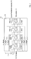
- Fig. 1 exemplary shows a possible architecture of parts 100 of an optical receiver circuit, in particular comprising an exemplary transimpedance amplifier circuit 101 and an exemplary photo diode 104.
- an exemplary transimpedance amplifier circuit 101 is shown with an input 102 to receive an input current signal from the at least one photo detector 104 and being configured to convert the received input, e.g. an input current signal, to an output voltage signal 103 to generate an output signal 103 of the transimpedance amplifier circuit.
- the DC restoration component and the automatic gain control component are not shown in this example.
- the transimpedance amplifier circuit 101 comprises an exemplary plurality of gain amplifier stages, e.g. exemplary gain amplifier stages 123, 124, 125, 126. Any other number of gain amplifier stages can be implemented as well.
- Said exemplary gain amplifier stages 123, 124, 125, 126 comprise exemplary gain amplifiers 119, 120, 121, 122 and exemplary local programmable feedback resistors (Rlfs) 105, 109, 106, 110, 107, 111, 108 and 112.
- Rlfs local programmable feedback resistors
- programmable feedback resistors for controlling the equivalent transimpedance of the transimpedance amplifier circuit 101 that are connected between the input 102 of the transimpedance amplifier circuit 101 and the output, i.e. output signal 103, or that are connected between the input 102 of the transimpedance amplifier circuit 101 and outputs of different gain amplifier stages may also be referred to as global programmable feedback resistors.
- the local programmable feedback resistors 105 and 109 can be understood also as a (global) programmable feedback resistors for controlling the (equivalent) transimpedance of the transimpedance amplifier circuit 101 in case of using / having only a single / the first gain amplifier stage 123.
- An exemplary sequence for controlling the equivalent transimpedance of the transimpedance amplifier circuit 101 may comprise:
- An exemplary sequence for controlling the gain of the transimpedance amplifier circuit 101 may comprise:
- Fig. 2 exemplary shows a further possible architecture of an optical receiver circuit 200.
- Said exemplary optical receiver circuit 200 can comprise an automatic gain control component 204 and DC restoration component 205, wherein said DC restoration component 205 can inter alia comprise a low-pass filter 208.
- the optical receiver circuit 200 comprises an exemplary transimpedance amplifier circuit 201 with input 202 and output 203 and with an exemplary plurality of gain amplifier stages, from which only an exemplary subset, namely the gain amplifier stages 209, 210, 211 are explicitly shown and denoted.
- Said gain amplifier stages can, analogous to the transimpedance amplifier circuit depicted in Fig. 1 , comprise exemplary gain amplifiers 212, 213, 214 and exemplary local programmable feedback resistors 215, 216, 217, 218, 219 and 220.
- an exemplary shunt programmable resistor 224 is shown that can short the output of the last gain amplifier stage 211.
- the transimpedance amplifier circuit 201 may comprise a plurality of programmable feedback resistors, e.g. global programmable feedback resistors, 226, 227 for controlling the equivalent transimpedance of the transimpedance amplifier circuit, wherein said programmable feedback resistors, e.g. global programmable feedback resistors, 226, 227 for controlling the equivalent transimpedance of the transimpedance amplifier circuit can be connected between the input 202 of the transimpedance amplifier circuit 201 and the output 203 of the transimpedance amplifier circuit 201 or between the input 202 of the transimpedance amplifier circuit 201 and the outputs of different gain amplifier stages.
- programmable feedback resistors e.g. global programmable feedback resistors, 226, 227 for controlling the equivalent transimpedance of the transimpedance amplifier circuit
- a fixed resistor 221, 225 connected in parallel between input and output of transimpedance amplifier circuit 201 can be used to limit the maximum value of the equivalent transimpedance of the transimpedance amplifier circuit 201.
- exemplary buffers 222, 223 are shown that can isolate the output of the last gain amplifier stage 211.
- the exemplary optical receiver circuit 200 can comprise two photo detectors, e.g. photo diodes, 206, 207, wherein one photo detector 207 is configured to receive the input light signal and the other photo detector 206 is shielded from the input light signal and the transimpedance amplifier circuit 201 can have a differential topology with one branch 228, e.g. the positive branch, of the transimpedance amplifier circuit 201 being connected to the photo detector 207 that is configured to receive the light signal and with the other branch 229, e.g. the negative branch, of the transimpedance amplifier circuit 201 being connected to the photo detector 206 that is shielded from the light signal.
- the transimpedance amplifier circuit 201 can have a differential topology with one branch 228, e.g. the positive branch, of the transimpedance amplifier circuit 201 being connected to the photo detector 207 that is configured to receive the light signal and with the other branch 229, e.g. the negative branch, of the transimpedance amplifier circuit 201 being connected to the photo detector
- said possible negative branch of the transimpedance amplifier circuit could be connected to an equivalent electrical model (not shown) of a photo detector, e.g. an equivalent electrical model of a photodiode, for example, to a circuit comprising a resistor and/or capacitor.
- Such a possible differential architecture can inter alia improve the Power Supply Ratio (PSRR) and Common Mode Rejection Ratio (CMRR) as well as the common noise immunity.
- PSRR Power Supply Ratio
- CMRR Common Mode Rejection Ratio
- the automatic gain control component 204 can be in communication with some or all programmable feedback resistors of the optical receiver circuit 200, i.e., for example, with both the local programmable feedback resistors 215, 216, 217, 218, 219, 220 for controlling the gain of the respective gain amplifier stage and with some or all of the programmable feedback resistors 226, 227 for controlling the equivalent transimpedance of the transimpedance amplifier circuit based on the signal output by the DC restoration component 205.
- R ctrl ⁇ M+1:N> and R ctrl ⁇ M+1:N> shown in Fig. 2 can be understood as referring to the possible plurality of transistors comprised in the programmable feedback resistors.
- said programmable feedback resistors can follow an activation sequence, for example, resistors 226, 227, 219 and 220 can be activated first, and after, resistors 215, 216, 217, 218.
- Fig. 3 exemplary shows a possible architecture of an optical receiver circuit 300 for the purpose of better understanding some aspects of the present invention.
- Said exemplary optical receiver circuit 300 can comprise an automatic gain control component 307 and DC restoration component 308, wherein said DC restoration component 308 can inter alia comprise a low-pass filter (not shown).
- the optical receiver circuit 200 comprises an exemplary transimpedance amplifier circuit 303 with input 301 and output 302 and with an exemplary gain amplifier stage 312.
- Said gain amplifier stage 312 can, analogous to the transimpedance amplifier circuits depicted before, comprise an exemplary gain amplifier 304 and exemplary local programmable feedback resistors 305 and 306 that in the case shown also can act as global programmable feedback resistors and for controlling the (equivalent) transimpedance of the transimpedance amplifier circuit 303 based on the signal output by the DC restoration component 308 to provide a constant output voltage amplitude for different current ranges of the input current signal.
- the gain of the gain amplifier stage(s) should preferably be sufficiently high in order to get the maximum bandwidth of the current to voltage transimpedance amplifier response, in particular for high equivalent transimpedance values.
- the transimpedance amplifier circuit can therefore comprise more than one gain amplifier stage.
- the bandwidth ⁇ -3dB of the transimpedance amplifier circuit with respect to the 3-dB point can be approximated by ⁇ ⁇ 3 dB ⁇ 2 A 0 R F C T , wherein, for example, A 0 is the open-loop gain of the gain amplifier of a gain amplifier stage, R F is the equivalent resistance of a feedback resistor and C F is the total equivalent input capacitance of the gain amplifier.
- the transimpedance amplifier circuit 303 can comprise / can be followed by an output buffer 311, e.g. a unity gain amplifier or voltage follower, to isolate an/the output node of the transimpedance amplifier circuit.
- an output buffer 311 e.g. a unity gain amplifier or voltage follower
- the exemplary optical receiver circuit 300 can comprise two photo detectors, e.g. photo diodes, 310, 309, wherein one photo detector 309 is configured to receive the input light signal and the other photo detector 310 is shielded from the input light signal and the transimpedance amplifier circuit 303 can have a differential topology with one branch, e.g. the positive branch, of the transimpedance amplifier circuit 303 being connected to the photo detector 309 that is configured to receive the light signal and with the other branch, e.g. the negative branch, of the transimpedance amplifier circuit 303 being connected to the photo detector 310 that is shielded from the light signal.
- the transimpedance amplifier circuit 303 can have a differential topology with one branch, e.g. the positive branch, of the transimpedance amplifier circuit 303 being connected to the photo detector 309 that is configured to receive the light signal and with the other branch, e.g. the negative branch, of the transimpedance amplifier circuit 303 being connected to the photo detector 310 that is shielde
- said possible negative branch of the transimpedance amplifier circuit could be connected to an equivalent electrical model (not shown) of a photo detector, e.g. an equivalent electrical model of a photodiode, for example, to a circuit comprising a resistor and/or capacitor.
- the photo detector e.g. photo diode 309
- V DD is connected to V DD for illustration purposes only
- other connections such as anode to ground, are also possible, depending on the nature of the photo diode.
- Fig. 4 exemplary shows a time series 400 of an exemplary input current signal 401, e.g. an exemplary photocurrent signal from a photo detector, e.g. a photo diode (not shown).
- a photo detector e.g. a photo diode (not shown).
- This figure illustrates the transient evolution of a transmission signal for a given average optical light power level (i.e., for a given fiber length, temperature, process, etc).
- the time scales shown can, for example, be of the order of hundred of MHz or GHz.
- the exemplary input current signal 401 can vary between a maximum input current level 402 and a minimum input current level 404, and may have an average input current level denoted by the reference numeral 403.
- the difference between the maximum input current level 402 and the minimum input current level 404 can define the input voltage swing or variation of the input current.
- the transmission signal can take any value, and the optical receiver (circuit) is in charge of interpreting it as the digital transmitted signal.
- the average current 403 exemplary represents the DC component of the received input signal.
- this DC component is not necessarily needed to reconstruct the transmission signal in the receiver, it can be removed by, for example, a DC restoration component, such as for example the DC restoration component 308 of Fig. 3 .
- the average input current 403 can provide a good estimation of the maximum input amplitude of the received photocurrent.
- the maximum input current swing can be calculated using the average current 403 and for adapting the equivalent transimpedance of the transimpedance amplifier to get a defined output voltage swing at the output of the transimpedance amplifier.
- the average current variation can be up to three orders of magnitude or more.
- Fig. 5 exemplary shows a gain amplifier 500, for example, a gain amplifier of a first gain amplifier stage (not shown).
- the gain amplifier can comprise a cascoded transistor with a resistive load R load 501.
- a PMOS (p-channel metal-oxide-semiconductor) load may be used, when optimizing a desired balance between gain, input referred noise and corner variations.
- the cascoded transistor can be a cascoded NMOS (n-channel metal-oxide-semiconductor) field-effect transistor, which inter alia can improve the current noise characteristics of the transimpedance amplifier circuit (not shown), as the input referred noise of the transimpedance amplifier circuit can be inversely proportional to the equivalent transconductance of the input differential pair and the equivalent input capacitance.
- NMOS n-channel metal-oxide-semiconductor
- PMOS p-channel metal-oxide-semiconductor field-effect transistor
- a cascoded transistor can inter alia allow increasing the equivalent impedance of the input differential pair 504, 505 (of the transimpedance amplifier circuit) to obtain a higher gain.
- the gain and the output impedance of the gain amplifier can be scaled with the equivalent transimpedance of the transimpedance amplifier circuit (not shown).
- the bias current I bias , 503, of the input differential pair can inter alia be obtained from a transconductance control circuit (not shown) that keeps a constant transconductance along possible process/voltage/temperature (PVT) variations in the optical receiver circuit, thereby improving the stability control, linearity and noise performance of the optical receiver circuit under all conditions.
- a transconductance control circuit (not shown) that keeps a constant transconductance along possible process/voltage/temperature (PVT) variations in the optical receiver circuit, thereby improving the stability control, linearity and noise performance of the optical receiver circuit under all conditions.
- bias current I bias , 503 can vary with the PVT variations to facilitate keeping the gain constant for all PVT variations, thereby inter alia facilitating the closed-loop response and keeping a similar performance in all corners.
- the gain amplifier 500 can comprise a common-mode control component 502 for controlling the reverse bias voltage of the input photo detector, i.e. the input photo diode. This can inter alia improve the control and stability of the output common mode voltage and can improve the performance of the possible following gain amplifier stage.
- Fig. 6 exemplary shows an exemplary common-mode control circuitry component 600 that can be implemented in the gain amplifiers of a gain amplifier stage of a transimpedance amplifier circuit of an optical receiver circuit (not shown), i.e., for example, all gain amplifiers can have common-mode control circuitry component.
- a common-mode control circuitry component can serve to compensate the variations of the bias current I bias , without significantly influencing the amount of current going through the input differential pair and maintaining the transconductance properties and functionalities.
- the common-mode control circuitry component 600 can sample the output node of the gain amplifier stage (not shown) by means of two large resistors 602, 603 in order to avoid modifying the output impedance of the gain amplifier stage (not shown).
- Said large resistors 602, 603 may, for example, have resistance values in the range of hundreds of kilo-ohms to few mega-ohms.
- the common-mode can be compared to a reference value 601, V CM , and the difference can be low-pass filtered, for example, by means of a 1 kHz transconductance-capacitance filter.
- the common-mode can then be adjusted by subtracting the corresponding current from the output nodes, for example, by means of a transistor, for example, an NMOS transistor.
- the common-mode control circuitry component topology is not limited to the proposed transconductance-capacitance scheme or MOS transistor, but that the common-mode control circuitry component could be implemented by other means performing the functionalities and steps described above.
- Fig. 7 exemplary shows possible steps of a control sequence 700 for controlling the equivalent transimpedance of the transimpedance amplifier circuit of an optical receiver circuit (not shown) in a stable manner.
- the exemplary sequence steps can, for example, be carried out by an automatic gain control component (not shown) and can include one, some or all of the following steps and in varying order of steps:
- step 703 and 704 the resistive feedback of the other local programmable feedback resistors of other gain amplifier stage can be reduced to reduce the gain of the other gain amplifier stages and to further control the stability of the transimpedance amplifier circuit of an optical receiver circuit.
- Fig. 8 exemplary shows an implementation of a programmable feedback resistor 800, e.g. of a local or global programmable feedback resistor or of a programmable feedback resistor connected between the input and output of the transimpedance amplifier circuit.
- a programmable feedback resistor 800 e.g. of a local or global programmable feedback resistor or of a programmable feedback resistor connected between the input and output of the transimpedance amplifier circuit.
- some or each of the programmable feedback resistors can comprise a plurality of transistors 802, 803, 804, 805 connected in parallel and wherein the resistance of the programmable feedback resistors is controlled via the gate voltage(s) of their transistors 806, 807, 808, 809, and wherein some or all of the transistors 802, 803, 804, 805 of a programmable feedback resistor can have different characteristics, for example, can differ in scale or size, e.g. differ in their gate-width-to-gate-length ratio 810, 811, 812, e.g. in their gate-width-to-gate-length ratio from the first to the last transistor of the respective programmable feedback resistor.
- the possible different characteristics of said transistors can inter alia reduce linearity problems and improve the operation of the programmable feedback resistors at ohmic region for the full dynamic range.
- MOS transistors e.g. CMOS transistors
- V DS is the drain to source voltage
- V DS,Sat is the drain to source voltage when entering the saturation region and non-linear behavior occurs.
- V DS V GS - V th
- V GS the gate source voltage
- V th the threshold voltage
- the transistors can, for example, be configured and designed for maximizing the V GS operating point to improve the linearity behavior for the whole range of equivalent impedances.
- Such exemplary successively activations of the transistors of the programmable feedback resistors of the optical receiver circuit can improve the linearity of equivalent impedance transitions, for example, the linearity of equivalent impedance transitions from high equivalent impedance values to low equivalent impedance values.
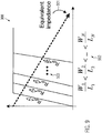
- Fig. 9 exemplary shows a possible linear decrease behavior 900 of the equivalent impedance 901 for a programmable feedback resistor (not shown) of an optical receiver circuit (not shown) when an exemplary gate-width to gate-length dependence 902 of the transistors (not shown) of a programmable feedback resistor is carried out.
- an activation sequence analogous to the one described above with an activation of the transistors from smaller gate-width-to-gate-length ratio to bigger gate-width-to-gate-length ratio, and wherein said transistors control the gate voltages 903 of the programmable feedback resistors (not shown).
- Fig. 10a exemplary shows a possible DC restoration component architecture 1000, wherein the DC restoration component can comprise a low-pass filter 1001.
- the DC restoration component can remove the input DC current, i.e. the average current, I avg , of the current signal generated by the at least one photo detector, i.e. the photocurrent, for example, by means of a closed-loop control, which can involve a low-pass filtering of the output voltage of the transimpedance amplifier circuit (TIA, not shown) to calculate its DC component, V DC .
- TIA transimpedance amplifier circuit
- the low-pass filter 1001 can be followed by a sequential voltage generator 1002 and a current source 1003 which generates the equivalent DC current to be subtracted from the transimpedance amplifier input and that can be built by means of a set of parallel transistor controlled by the sequential voltage control voltage V DC generated by the sequential voltage generator, which can be configured for a continuous control of the DC voltage.
- Fig.10b exemplary shows the linear behaviour 1004 of the DC input current in dependence of the calculated DC voltage component V DC for a possible DC restoration component architecture, such as, for example, the DC restoration component architecture 1000.
- Fig.10c exemplary shows the closed-loop control response behaviour 1006 of a possible transimpedance amplifier circuit architecture with a possible DC restoration component architecture together, such as, for example, the DC restoration component architecture 1000 and the transimpedance amplifier circuit architecture described above.
- Said lower corner frequency ⁇ pl or low frequency pole 1005 can be kept constant for all the possible transimpedance range, thereby preventing inter alia a baseline wandering of the communication signal processed by the optical receiver circuit. Furthermore, the equivalent transconductance g m,cs can move together with the equivalent transimpedance T z 0 .
- the DC current generated by the DC restoration component i.e. the DC current signal outputted by the DC restoration component
- the equivalent transconductance g m , cs of the current source can be reduced to reduce the current noise of the DC restoration injected at the input of the transimpedance amplifier.
- the use of the sequential voltage activation of the current source can help to minimize the current noise injection.
- the described architecture inter alia can allow keeping a constant T z 0 ⁇ g m,cs product and at the same time reducing the amount of noise injected into the transimpedance amplifier circuit input, as the transistors used in this architecture can, for example, as described above, e.g. Fig. 8 , be configured and designed for maximizing their gate source voltage V GS operating point.
- transistors that can be used are not limited to a MOS (metal-oxide-semiconductor), e.g. CMOS (complementary metal-oxide-semiconductor), architecture based implementation.
- MOS metal-oxide-semiconductor
- CMOS complementary metal-oxide-semiconductor
- Fig. 11 exemplary shows a possible sequential voltage control component 1100 for continuous voltage control which, for example, can be used in DC restoration component (not shown) of an optical receiver circuit as described above.
- the exemplary possible sequential voltage control component 1100 can receive an input current reference I ref and a signal V dc coming from a/the low pass filter (not shown), which can be translated into a current I in proportional to the output DC voltage of the DC restoration component (not shown).
- Said translated input voltage-dependent current I in can then be copied by means of a current mirror 1104 along an array of scaled of copies of the reference current I ref .
- a diode-connected transistor for example, a diode-connected NMOS transistor, can convert exceeding current into voltage and thereby building the sequential bits, e.g. rising from a minimum to a maximum value sequentially, along the array.
- a proper sizing i.e. a proper dimensioning of the width-to-gate length ratios, can exactly control the activation sequence.
- Fig. 12 exemplary shows an automatic gain control component 1200.
- the automatic gain control carried out by automatic gain control component 1200 can be based on a/the DC current 1209 generated by the DC restoration component (not shown) and a scaled version of the main transimpedance amplifier circuit (TIA), called dummy transimpedance amplifier circuit (dummy TIA) 1208.
- TIA main transimpedance amplifier circuit
- dummy TIA dummy transimpedance amplifier circuit
- the exemplary automatic gain control component 1200 can, for example, comprise at least one dummy gain amplifier stage with a dummy gain amplifier 1205 and dummy programmable feedback resistors 1206, 1207, as well as an output buffer.
- the dummy transimpedance amplifier circuit 1208 can have, for example, the same number of dummy gain amplifier stages, the same number of dummy gain amplifiers and the same number of dummy programmable feedback resistors as the main transimpedance amplifier circuit (not shown), but their characteristic values and properties can be scaled such as to have a lower power consumption but the same DC characteristics (e.g. same equivalent DC gain and same equivalent transimpedance) to facilitate correct calibration of the optical receiver circuit.
- the DC current i.e. the average current, I avg
- the DC current can be proportional to the amplitude of the AC (alternating current) component of the input signal.
- the reference signal 1201 can, for example a reference voltage, represent a/the maximum output voltage amplitude allowed at the main transimpedance amplifier circuit output (not shown).
- the possible block following the dummy transimpedance amplifier circuit 1208 can have a high gain, e.g. of up to 60dB or more, and can generate an output voltage proportional to the difference between the dummy transimpedance amplifier circuit 1208 and the reference voltage 1201.
- Said block may further comprise a sequential voltage generator 1203 and that can be similar to the possible sequential voltage generator of the DC restoration component.
- Said sequential voltage generator 1203 can create sequentially voltage control signals 1202 ( R ctrl ⁇ 1: N >) that can drive the programmable feedback resistors of both the dummy transimpedance amplifier circuit 1208 and the main transimpedance amplifier circuit.
- Fig. 13 exemplary shows an optical communication system 1300 comprising an optical transmitter 1301, an optical fiber link 1302, e.g. a plastic fiber, and an optical receiver 1303.
- an optical communication system 1300 comprising an optical transmitter 1301, an optical fiber link 1302, e.g. a plastic fiber, and an optical receiver 1303.
- a light emitting device e.g. light emitting diode (LED) 1306 driven by an LED driving circuit 1305, of the optical transmitter, outputs an optical signal that is fed into an optical fiber link 1302, e.g. a plastic fiber, which guides the optical signal to a light receiving device, the optical receiver 1303, where the light is for example received by a photo diode 1307.
- the light received by the photo diode 1307 generates a photocurrent that is converted, for example, by a trans-impedance amplifier circuit (TIA) 1308 according to and consistent with the exemplary architecture(s) described above, into an electrical voltage output signal 1309.
- TIA trans-impedance amplifier circuit
- the optical receiver 1303 comprises an optical receiver circuit 1304 according to and consistent with the exemplary architecture(s) of an optical receiver circuit described above.
- the exemplary architecture(s) of an optical receiver circuit described above is/are not limited to a MOS (metal-oxide-semiconductor) architecture based implementation.
- the design of the architecture of an optical receiver circuit exemplary described above is also compatible with any other technology, such as, for example, Bipolar (bipolar junction transistor technology), BiCMOS (combination of bipolar junction transistor technology and complementary metal-oxide-semiconductor technology), GaAs (Gallium Arsenide) based technology, etc.
Claims (14)
- Optische Empfängerschaltung (200), umfassend:wenigstens einen Fotodetektor (207), der dazu eingerichtet ist, ein empfangenes Lichtsignal in ein Eingangsstromsignal umzuwandeln,eine Transimpedanz-Verstärkerschaltung (201) mit einem Eingang zum Empfangen des Eingangsstromsignals von dem wenigstens einen Fotodetektor (207) und zum Umwandeln des empfangenen Eingangsstromsignals in ein Ausgangsspannungssignal zum Erzeugen eines Ausgangssignals der Transimpedanz-Verstärkerschaltung (201), wobei die Transimpedanz-Verstärkerschaltung mehrere Verstärkungsverstärkerstufen (209, 210, 211) umfasst,eine Gleichstrom-Wiederherstellungskomponente (205), wobei die Gleichstrom-Wiederherstellungskomponente (205) dazu eingerichtet ist, das Ausgangsspannungssignal der Transimpedanz-Verstärkerschaltung (201) zum Wiederherstellen der Gleichstrom-Komponente des empfangenen Stromsignals zu empfangen, und dazu eingerichtet ist, ein entsprechendes Stromsignal auszugeben,eine automatische Verstärkungssteuerkomponente (204), die zum Steuern der äquivalenten Transimpedanz der Transimpedanz-Verstärkerschaltung über wenigstens einen programmierbaren Rückkopplungswiderstand (226, 227) auf der Grundlage des von der Gleichstrom-Wederherstellungskomponente (205) ausgegebenen Signals eingerichtet ist, um eine konstante Ausgangsspannungsamplitude für verschiedene Strombereiche des Eingangsstromsignals bereitzustellen, wobei wenigstens einige der Verstärkungsverstärkerstufen (209, 210, 211) einen Verstärkungsverstärker (212, 213, 214) und wenigstens einen lokalen programmierbaren Rückkopplungswiderstand (215, 216, 217, 218, 219, 220) zum Steuern der Verstärkung der jeweiligen Verstärkungsverstärkerstufe (209, 210, 211) umfassen und die automatische Verstärkungssteuerkomponente (204) weiterhin dazu eingerichtet ist, wenigstens einige der lokalen programmierbaren Rückmeldungswiderstände (215, 216, 217, 218, 219, 220) der Verstärkungsverstärkerstufen basierend auf dem Signal zu steuern, das von der Gleichstrom-Wiederherstellungskomponente (205) ausgegeben wird, undder wenigstens eine programmierbare Rückkopplungswiderstand (226, 227) zum Steuern der äquivalenten Transimpedanz der Transimpedanz-Verstärkerschaltung (201) zwischen dem Eingang der Transimpedanz-Verstärkerschaltung und dem Ausgangssignal der Transimpedanz-Verstärkerschaltung angeordnet ist.
- Optische Empfängerschaltung (200) nach dem vorhergehenden Anspruch, umfassend zahlreiche programmierbare Rückkopplungswiderstände (226, 227, 215, 216, 105, 109, 113, 114, 115, 116, 117, 118) zum Steuern der äquivalenten Transimpedanz der Transimpedanz-Verstärkerschaltung (201, 101), wobei wenigstens einige der programmierbaren Rückkopplungswiderstände (215, 216, 105, 109, 114, 115, 116, 117) zum Steuern der äquivalenten Transimpedanz der Transimpedanz-Verstärkerschaltung zwischen den Eingang der Transimpedanz-Verstärkerschaltung und Ausgänge der verschiedenen Verstärkerstufen (123, 124, 125, 126) geschaltet sind.
- Optische Empfängerschaltung (200) nach einem der vorhergehenden Ansprüche, weiterhin umfassend einen festen Widerstand (221, 225), der zwischen den Eingang und das Ausgangssignal der Transimpedanz-Verstärkerschaltung zur Begrenzung der maximalen äquivalenten Transimpedanz der Transimpedanz-Verstärkerschaltung geschaltet ist, und/oder
wobei die Gleichstrom-Wiederherstellungskomponente (205) dazu eingerichtet ist, die Gleichstrom-Komponente des empfangenen Stromsignals zu subtrahieren, und die automatische Verstärkungssteuerkomponente (204) zum Steuern der äquivalenten Transimpedanz der Transimpedanz-Verstärkerschaltung (201) basierend auf einer Kopie der subtrahierten Gleichstrom-Komponente eingerichtet ist. - Optische Empfängerschaltung (200) nach einem der vorhergehenden Ansprüche, wobei die optische Empfängerschaltung zwei Fotodetektoren (206, 207) umfasst, wobei ein Fotodetektor (207) zum Empfangen des Lichtsignals eingerichtet ist, und der andere Fotodetektor (206) von dem Lichtsignal abgeschirmt ist und die Transimpedanz-Verstärkerschaltung (201) eine differentielle Topologie hat, bei der ein Zweig, z.B. der positive Zweig (228) der Transimpedanz-Verstärkerschaltung, mit dem Fotodetektor (207) verbunden ist, der dazu eingerichtet ist, das Lichtsignal zu empfangen, und der andere Zweig, z.B. der negative Zweig (229) der Transimpedanz-Verstärkerschaltung, mit dem Fotodetektor (206) verbunden ist, der von dem Lichtsignal abgeschirmt ist, oder
die optische Empfängerschaltung eine Transimpedanz-Verstärkerschaltung mit einer differentiellen Topologie umfasst, bei der ein Zweig, z.B. der positive Zweig der Transimpedanz-Verstärkerschaltung mit dem Fotodetektor verbunden ist, der dazu eingerichtet ist, das Lichtsignal zu empfangen, und der andere Zweig, z.B. der negative Zweig der Transimpedanz-Verstärkerschaltung, mit einem äquivalenten elektrischen Modell der Fotodiode, beispielsweise mit einer Schaltung verbunden ist, die einen Widerstand und/oder einen Kondensator aufweist. - Optische Empfängerschaltung (200) nach einem der vorhergehenden Ansprüche, bei der wenigstens einige der lokalen programmierbaren Rückkopplungswiderstände zum Steuern der Verstärkung der Verstärkerstufen (217, 218, 219, 220) mit lokalen Eingängen und Ausgängen von einigen der Verstärkungsverstärkerstufen verbunden sind und/oder wenigstens einige der lokalen programmierbaren Rückkopplungswiderstände zum Steuern der Verstärkung der Verstärkungsverstärkerstufen dazu eingerichtet sind sind, die Ausgaben von einigen der Verstärkungsverstärkerstufen (224) zu verkürzen.
- Optische Empfängerschaltung (200) nach einem der vorhergehenden Ansprüche, bei der die wenigstens eine Verstärkungsverstärkerstufe ein differentielles Paar, z.B. einen Kaskodentransistor mit einer ohmschen Last (501), Rload, oder mit einer aktiven Last, beispielsweise mit einer Last eines p-Kanal-Metalloxid-Halbleiter-Feldeffekttransistors, PMOS, umfasst, und/oder
wobei wenigstens eine, einige oder jede Verstärkungsverstärkerstufe eine Gleichtaktsteuerschaltung (502) zum Bereitstellen eines Signals umfassen, das zum Steuern der Sperrvorspannung des Fotodetektors geeignet ist. - Optische Empfängerschaltung (200) nach einem der vorhergehenden Ansprüche, wobei die optische Empfängerschaltung dazu eingerichtet ist, einen, einige oder alle der folgenden Schritte auszuführen:Berechnen eines Durchschnittsstroms des Stromsignals, das von dem wenigstens einen Fotodetektor erzeugt wird, zum Beispiel basierend auf einer Kopie des von der Gleichstrom-Wiederherstellungskomponente (205) ausgegebenen Stroms,Verwenden des berechneten Durchschnittsstroms zum Berechnen einer erforderlichen äquivalenten Transimpedanz der Transimpedanz-Verstärkerschaltung und zum Steuern der äquivalenten Transimpedanz der Transimpedanz-Verstärkerschaltung (201), um eine konstante Amplitude der Ausgangsspannung (203) für unterschiedliche Strombereiche des Eingangsstromsignals bereitzustellen,Reduzieren der Verstärkung der Verstärkerstufen (209, 210, 211).
- Optische Empfängerschaltung (200) nach einem der vorhergehenden Ansprüche, bei der die automatische Verstärkungssteuerkomponente (204) dazu eingerichtet ist, einen, einige oder sämtliche der folgenden Schritte (702, 703, 704) zum Steuern der äquivalenten Transimpedanz der Transimpedanz-Verstärkerschaltung (201) auszuführen:Verwenden des von der Gleichstrom-Wiederherstellungskomponente (205) ausgegebenen Stroms, um eine erforderliche äquivalente Transimpedanz der Transimpedanz-Verstärkerschaltung (201) zu berechnen,Beginnen, die äquivalente Transimpedanz der Transimpedanz-Verstärkerschaltung (201) zu verringern, indem die Impedanz des wenigstens einen programmierbaren Rückkopplungswiderstands (225, 226), der zwischen den Eingang und den Ausgang der Transimpedanz-Verstärkerschaltung geschaltet ist, verringert wird,sobald die Impedanz des wenigstens einen programmierbaren Rückkopplungswiderstandes (226, 227), der zwischen den Eingang und den Ausgang der Transimpedanz-Verstärkerschaltung geschaltet ist, auf einen gegebenen Minimalwert gesetzt wird, sequentielles Verringern der Impedanz möglicher weiterer programmierbarer Rückkopplungswiderstände, die zwischen den Eingang der Transimpedanz-Verstärkerschaltung und Ausgänge von verschiedenen Verstärkungsverstärkerstufen (215, 216) geschaltet sind, indem beispielsweise mit der Verringerung der Impedanz eines programmierbaren Rückkopplungswiderstandes begonnen wird, der zwischen den Eingang der Transimpedanz-Verstärkerschaltung und den Ausgang der letzten Verstärkungsverstärkerstufe geschaltet ist.
- Optische Empfängerschaltung (200) nach einem der vorhergehenden Ansprüche, bei der die automatische Verstärkungssteuerkomponente (204) weiterhin dazu eingerichtet ist, den folgenden Schritt auszuführen:
Steuern der Verstärkung der Verstärkungsverstärkerstufen (209, 210, 211) durch Steuern, z.B. sequenzielles Reduzieren, der Widerstandsrückkopplung oder der Shunt-Widerstände der lokalen programmierbaren Rückkopplungswiderstände der Verstärkungsverstärkerstufen (217, 218, 219, 220, 224), beispielsweise durch Starten des Steuerns, z.B. Reduzierens, der Widerstandsrückkopplung des lokalen programmierbaren Rückkopplungswiderstands der letzten Verstärkungsverstärkerstufe (219, 220). - Optische Empfängerschaltung (200) nach einem der vorhergehenden Ansprüche, bei der einige oder jeder der programmierbaren Rückkopplungswiderstände (215, 216, 217, 218, 219, 220, 224, 225, 226) eine Mehrzahl von Transistoren (802, 803, 804, 805) aufweist, die parallel geschaltet sind und der Widerstand der lokalen programmierbaren Rückkopplungswiderstände über die Gate-Spannung (806, 807, 808, 809) ihrer Transistoren gesteuert wird, wobei einige oder alle der Transistoren eines programmierbaren Rückkopplungswiderstandes unterschiedliche Eigenschaften aufweisen, die sich beispielsweise im Maßstab oder der Größe unterscheiden, z.B. sich in ihrem Gate-Breite-zu-Gate-Längen-Verhältnis unterscheiden, z.B. in ihrem Gate-Breite-zu-Gate-Längen-Verhältnis von dem ersten zu dem letzten Transistor des jeweiligen programmierbaren Rückkopplungswiderstandes zunehmen.
- Optische Empfängerschaltung (200) nach dem vorhergehenden Anspruch, bei der die Transistoren eines programmierbaren Rückkopplungswiderstandes dazu eingerichtet sind, in Sequenz (900) aktiviert zu werden, zum Beispiel dazu eingerichtet sind, in Sequenz vom ersten bis zum letzten Transistor des jeweiligen programmierbaren Rückkopplungswiderstandes aktiviert zu werden.
- Optische Empfängerschaltung (200) nach einem der vorhergehenden Ansprüche, bei der die Gleichstrom-Wiederherstellungskomponente (205) einen sequentiellen Spannungsgenerator (1002) umfasst, wobei der sequentielle Spannungsgeneratorausgang eine Stromquelle antreibt, die eine Mehrzahl von skalierten Transistoren (1003) umfasst, und die skalierten Transistoren so konfiguriert sind, dass sie nacheinander aktiviert werden, um die Gleichstromausgabe der Gleichstrom-Wiederherstellungskomponente zu erhöhen, wobei zum Beispiel die Gleichstrom-Wiederherstellungskomponente eine Niederspannungsdurchlassfilter (1001) umfasst, das mit dem Ausgang der Transimpedanz-Verstärkerschaltung (203) verbunden ist, wobei der Ausgang des Tiefpassfilters (1103) als Eingang für den sequentiellen Spannungsgenerator (1002) verwendet wird und der Gleichstromausgang der Gleichstrom-Wiederherstellungskomponente mit dem Ausgang des wenigstens einen Fotodetektors (207) verbunden ist, der mit dem Eingang (228) der Transimpedanz-Verstärkerschaltung (201) verbunden ist, und/oder
die automatische Verstärkungssteuerkomponente (204) eine Dummy-Transimpedanz-Verstärkerschaltung (1208) umfasst, die eine skalierte Version der Transimpedanz-Verstärkerschaltung (201) gemäß einem der vorhergehenden Ansprüche ist, wobei die Dummy-Transimpedanz-Verstärkerschaltung (1208) eine Vielzahl von Blindverstärkungsverstärkerstufen (1205) aufweist, und die Dummy-Transimpedanz-Verstärkerschaltung (1208) dazu eingerichtet ist, eine Kopie des von der Gleichstrom-Wiederherstellungskomponente (1209) ausgegebenen Gleichstroms als Eingabe zu empfangen, und die Dummy-Transimpedanz-Verstärkerschaltung weiterhin dazu eingerichtet ist, das empfangene Eingangsstromsignal in ein Spannungssignal umzuwandeln, um ein Ausgangssignal (1202) zum Steuern der äquivalenten Transimpedanz der Transimpedanz-Verstärkerschaltung zu erzeugen, und jede Dummy-Verstärkungsverstärkerstufe zum Beispiel einen Dummy-Verstärkungsverstärker und wenigstens einen lokalen programmierbaren Dummy-Rückkopplungswiderstand umfasst. - Optische Empfängerschaltung (200) nach dem vorhergehenden Anspruch, bei der die Dummy-Transimpedanz-Verstärkerschaltung (1208) die gleiche äquivalente Transimpedanz für einen gegebenen programmierten Zustand der programmierbaren Dummy-Rückkopplungswiderstände (1206, 1207) aufweist, wie die äquivalente Transimpedanz des Transimpedanzverstärkers, der mit dem gleichen programmierten Zustand der programmierbaren Rückkopplungswiderstände konfiguriert ist und bei dem die automatische Verstärkungssteuerkomponente dazu eingerichtet ist, einen, einige oder alle der folgenden Schritte auszuführen:Verwenden einer Kopie des von der Gleichstrom-Wiederherstellungskomponente (1209) ausgegebenen Gleichstroms als einen Eingang der Dummy-Transimpedanz-Verstärkerschaltung, um diesen Strom in eine Spannung umzuwandeln, die proportional zu der erforderlichen Transimpedanz ist,Vergleichen der Ausgabe der Dummy-Transimpedanz-Verstärkerschaltung mit einer gegebenen Referenzspannung (1201) und basierend auf diesem Vergleich Erzeugen eines Satzes von Gate-Steuerspannungen (1202), um die Transimpedanz der Dummy-Transimpedanz-Verstärkerschaltung mittels der programmierbaren Dummy-Rückkopplungswiderstände zu programmieren,Verwenden der erzeugten Gate-Steuerspannungen (1202), um die äquivalente Transimpedanz der Transimpedanz-Verstärkerschaltung (201) auf einen Wert einzustellen, der die Ausgangsspannungsamplitude (203) der Transimpedanz-Verstärkerschaltung auf einen gewünschten Wert einstellt.
- Optischer Empfänger (1303) zur Verwendung in einem optischen Kommunikationssystem (1300) mit wenigstens einer optischen Empfängerschaltung (1304) nach einem der vorhergehenden Ansprüche.
Priority Applications (7)
| Application Number | Priority Date | Filing Date | Title |
|---|---|---|---|
| EP16382431.1A EP3297184B1 (de) | 2016-09-15 | 2016-09-15 | Transimpedanzverstärker für optische hochgeschwindigkeitskommunikation auf grundlage linearer modulationen |
| ES16382431T ES2714387T3 (es) | 2016-09-15 | 2016-09-15 | Amplificador de transimpedancia para comunicaciones ópticas de alta velocidad basadas en modulaciones lineales |
| US15/675,927 US10461867B2 (en) | 2016-09-15 | 2017-08-14 | Transimpedance amplifier for high-speed optical communications based on linear modulation |
| BR102017019132-0A BR102017019132A2 (pt) | 2016-09-15 | 2017-09-06 | Circuito receptor óptico, e, receptor óptico para uso em um sistema de comunicação óptica |
| JP2017175530A JP6684768B2 (ja) | 2016-09-15 | 2017-09-13 | 光受信機回路および光受信機 |
| KR1020170118663A KR102037737B1 (ko) | 2016-09-15 | 2017-09-15 | 선형 변조에 기초한 고속 광통신용 트랜스임피던스 증폭기 |
| CN201710833539.9A CN107835054B (zh) | 2016-09-15 | 2017-09-15 | 用于基于线性调制的高速光通信的跨阻放大器 |
Applications Claiming Priority (1)
| Application Number | Priority Date | Filing Date | Title |
|---|---|---|---|
| EP16382431.1A EP3297184B1 (de) | 2016-09-15 | 2016-09-15 | Transimpedanzverstärker für optische hochgeschwindigkeitskommunikation auf grundlage linearer modulationen |
Publications (2)
| Publication Number | Publication Date |
|---|---|
| EP3297184A1 EP3297184A1 (de) | 2018-03-21 |
| EP3297184B1 true EP3297184B1 (de) | 2018-12-12 |
Family
ID=57018108
Family Applications (1)
| Application Number | Title | Priority Date | Filing Date |
|---|---|---|---|
| EP16382431.1A Active EP3297184B1 (de) | 2016-09-15 | 2016-09-15 | Transimpedanzverstärker für optische hochgeschwindigkeitskommunikation auf grundlage linearer modulationen |
Country Status (7)
| Country | Link |
|---|---|
| US (1) | US10461867B2 (de) |
| EP (1) | EP3297184B1 (de) |
| JP (1) | JP6684768B2 (de) |
| KR (1) | KR102037737B1 (de) |
| CN (1) | CN107835054B (de) |
| BR (1) | BR102017019132A2 (de) |
| ES (1) | ES2714387T3 (de) |
Families Citing this family (15)
| Publication number | Priority date | Publication date | Assignee | Title |
|---|---|---|---|---|
| US11275879B2 (en) * | 2017-07-13 | 2022-03-15 | Diatog Semiconductor (UK) Limited | Method for detecting hazardous high impedance nets |
| US10944486B2 (en) * | 2017-12-06 | 2021-03-09 | Elenion Technologies, Llc | DC current cancellation scheme for an optical receiver |
| US10749716B2 (en) * | 2018-04-09 | 2020-08-18 | Texas Instruments Incorporated | Signal path linearizer |
| CN109274341A (zh) * | 2018-08-19 | 2019-01-25 | 天津大学 | 基于标准cmos工艺可见光通信的全差分跨阻抗放大器 |
| CN109600122A (zh) * | 2018-12-14 | 2019-04-09 | 北京倍肯恒业科技发展股份有限公司 | 可变跨阻放大器电流-电压转换电路 |
| KR20210124982A (ko) * | 2019-01-10 | 2021-10-15 | 스카이워크스 솔루션즈, 인코포레이티드 | 전력 증폭기들의 바이어싱을 위한 장치 및 방법들 |
| WO2020177081A1 (zh) * | 2019-03-05 | 2020-09-10 | 深圳市傲科光电子有限公司 | 一种跨阻放大器和跨阻放大器电路 |
| JP7344506B2 (ja) * | 2019-09-02 | 2023-09-14 | 日本電信電話株式会社 | トランスインピーダンスアンプ |
| KR20210041358A (ko) | 2019-10-07 | 2021-04-15 | 삼성전자주식회사 | 재구성가능 아날로그 필터 및 이를 포함하는 집적 회로 |
| KR102516793B1 (ko) * | 2021-02-26 | 2023-04-03 | 주식회사 실리콘파이브 | 포토 다이오드 내장 반도체의 온도 보상 회로 |
| CN113114118A (zh) * | 2021-04-22 | 2021-07-13 | 西安交通大学 | 一种超级差分跨阻放大器结构及光电二极管连接方法 |
| US11843418B2 (en) * | 2021-09-16 | 2023-12-12 | Cisco Technology, Inc. | DC and offset cancellation for fully differential optical receiver |
| CN113852420A (zh) * | 2021-11-29 | 2021-12-28 | 之江实验室 | 一种自适应滤波的光功率检测电路及方法 |
| CN115173956B (zh) * | 2022-07-26 | 2023-07-18 | 烽火通信科技股份有限公司 | 光电探测接收机 |
| CN117294264B (zh) * | 2023-11-22 | 2024-03-12 | 成都明夷电子科技有限公司 | 一种光接收机用低噪声跨阻放大器 |
Family Cites Families (19)
| Publication number | Priority date | Publication date | Assignee | Title |
|---|---|---|---|---|
| US4019048A (en) * | 1976-03-22 | 1977-04-19 | Bell Telephone Laboratories, Incorporated | Regenerator for an optical transmission system |
| US4829267A (en) * | 1987-09-04 | 1989-05-09 | Digital Equipment Corporation | Automatic DC restorer stage for servo data amplifier |
| US5606277A (en) * | 1995-06-23 | 1997-02-25 | Linear Technology Corporation | AC coupling loops for current-to-voltage transimpedance amplifiers and methods of using same |
| US6529070B1 (en) | 1999-10-25 | 2003-03-04 | Texas Instruments Incorporated | Low-voltage, broadband operational amplifier |
| US6552605B1 (en) * | 2002-02-11 | 2003-04-22 | Intel Corporation | Differential transimpedance amplifier for optical communication |
| JP3940616B2 (ja) | 2002-02-25 | 2007-07-04 | 松下電器産業株式会社 | 光受信回路 |
| US6844784B1 (en) * | 2002-11-26 | 2005-01-18 | Finisar Corporation | Wide dynamic range transimpedance amplifier |
| KR20060017819A (ko) * | 2003-05-27 | 2006-02-27 | 조지아 테크 리서치 코오포레이션 | 부동 게이트 기준 회로 |
| US7406268B2 (en) * | 2003-08-27 | 2008-07-29 | Avago Technologies Limited | Optical receiver circuit |
| US7418213B2 (en) * | 2004-08-12 | 2008-08-26 | Finisar Corporation | Transimpedance amplifier with integrated filtering and reduced parasitic capacitance |
| JP4253308B2 (ja) | 2005-03-16 | 2009-04-08 | 株式会社東芝 | 光受信回路装置 |
| US20060216042A1 (en) * | 2005-03-24 | 2006-09-28 | Yeo Kok S | Automatic gain control circuit for infrared receiver |
| JP2008205614A (ja) | 2007-02-16 | 2008-09-04 | Nec Electronics Corp | 受光回路 |
| CN101997499B (zh) | 2010-12-15 | 2013-09-11 | 烽火通信科技股份有限公司 | 一种用于跨阻放大器的agc电路 |
| EP2672637B1 (de) | 2012-06-08 | 2018-03-14 | Knowledge Development for POF, S.L. | Rahmenstruktur für adaptive Datenkommunikationen über eine optische Kunststofffaser |
| JP5731615B2 (ja) | 2013-10-25 | 2015-06-10 | 日本電信電話株式会社 | トランスインピーダンスアンプ回路 |
| JP2015089047A (ja) * | 2013-10-31 | 2015-05-07 | 富士通オプティカルコンポーネンツ株式会社 | 光受信装置及び伝送装置 |
| CN204046530U (zh) | 2014-04-04 | 2014-12-24 | 嘉兴禾润电子科技有限公司 | 一种低噪声跨阻放大器及其光接收机前置放大器 |
| CN104539373A (zh) | 2014-12-30 | 2015-04-22 | 天津大学 | 交叉耦合结构的高速cmos单片集成光接收机前端电路 |
-
2016
- 2016-09-15 ES ES16382431T patent/ES2714387T3/es active Active
- 2016-09-15 EP EP16382431.1A patent/EP3297184B1/de active Active
-
2017
- 2017-08-14 US US15/675,927 patent/US10461867B2/en active Active
- 2017-09-06 BR BR102017019132-0A patent/BR102017019132A2/pt active Search and Examination
- 2017-09-13 JP JP2017175530A patent/JP6684768B2/ja active Active
- 2017-09-15 KR KR1020170118663A patent/KR102037737B1/ko active IP Right Grant
- 2017-09-15 CN CN201710833539.9A patent/CN107835054B/zh active Active
Non-Patent Citations (1)
| Title |
|---|
| None * |
Also Published As
| Publication number | Publication date |
|---|---|
| KR102037737B1 (ko) | 2019-10-29 |
| CN107835054A (zh) | 2018-03-23 |
| BR102017019132A2 (pt) | 2018-05-15 |
| JP6684768B2 (ja) | 2020-04-22 |
| US20180091231A1 (en) | 2018-03-29 |
| EP3297184A1 (de) | 2018-03-21 |
| CN107835054B (zh) | 2021-02-09 |
| KR20180030451A (ko) | 2018-03-23 |
| JP2018046561A (ja) | 2018-03-22 |
| US10461867B2 (en) | 2019-10-29 |
| ES2714387T3 (es) | 2019-05-28 |
Similar Documents
| Publication | Publication Date | Title |
|---|---|---|
| EP3297184B1 (de) | Transimpedanzverstärker für optische hochgeschwindigkeitskommunikation auf grundlage linearer modulationen | |
| EP3272038B1 (de) | Optische empfänger | |
| US6275114B1 (en) | Impedance matched CMOS transimpedance amplifier for high-speed fiber optic communications | |
| US10355655B2 (en) | Transimpedance amplifier (TIA) circuit having reduced power consumption, improved linearization and reduced peaking | |
| US9961725B2 (en) | LED driver for high-speed optical communications based on linear modulations | |
| US10312873B2 (en) | Split cascode circuits and related communication receiver architectures | |
| US8222590B2 (en) | Signal amplifier for optical receiver circuit | |
| US10511294B2 (en) | Cross-point offset adjustment circuit | |
| US11411542B2 (en) | Transimpedance amplifier circuit | |
| US11349444B2 (en) | Transimpedance amplifier circuit | |
| Jeong et al. | A 20-Gb/s 1.27 pJ/b low-power optical receiver front-end in 65nm CMOS | |
| US7245179B2 (en) | Auto gain controller | |
| US7088174B2 (en) | Offset cancellation and slice adjust amplifier circuit | |
| US20230305246A1 (en) | Opto-electronic assemblies | |
| JP2021111885A (ja) | 差動増幅回路 | |
| JP3906693B2 (ja) | 光受信差動回路および光受信装置 | |
| JP2021027586A (ja) | トランスインピーダンス増幅回路 | |
| JP2021022901A (ja) | トランスインピーダンス増幅回路 |
Legal Events
| Date | Code | Title | Description |
|---|---|---|---|
| PUAI | Public reference made under article 153(3) epc to a published international application that has entered the european phase |
Free format text: ORIGINAL CODE: 0009012 |
|
| STAA | Information on the status of an ep patent application or granted ep patent |
Free format text: STATUS: REQUEST FOR EXAMINATION WAS MADE |
|
| 17P | Request for examination filed |
Effective date: 20170512 |
|
| AK | Designated contracting states |
Kind code of ref document: A1 Designated state(s): AL AT BE BG CH CY CZ DE DK EE ES FI FR GB GR HR HU IE IS IT LI LT LU LV MC MK MT NL NO PL PT RO RS SE SI SK SM TR |
|
| AX | Request for extension of the european patent |
Extension state: BA ME |
|
| GRAP | Despatch of communication of intention to grant a patent |
Free format text: ORIGINAL CODE: EPIDOSNIGR1 |
|
| STAA | Information on the status of an ep patent application or granted ep patent |
Free format text: STATUS: GRANT OF PATENT IS INTENDED |
|
| INTG | Intention to grant announced |
Effective date: 20180824 |
|
| GRAS | Grant fee paid |
Free format text: ORIGINAL CODE: EPIDOSNIGR3 |
|
| GRAA | (expected) grant |
Free format text: ORIGINAL CODE: 0009210 |
|
| STAA | Information on the status of an ep patent application or granted ep patent |
Free format text: STATUS: THE PATENT HAS BEEN GRANTED |
|
| AK | Designated contracting states |
Kind code of ref document: B1 Designated state(s): AL AT BE BG CH CY CZ DE DK EE ES FI FR GB GR HR HU IE IS IT LI LT LU LV MC MK MT NL NO PL PT RO RS SE SI SK SM TR |
|
| REG | Reference to a national code |
Ref country code: GB Ref legal event code: FG4D |
|
| REG | Reference to a national code |
Ref country code: CH Ref legal event code: EP |
|
| REG | Reference to a national code |
Ref country code: AT Ref legal event code: REF Ref document number: 1077375 Country of ref document: AT Kind code of ref document: T Effective date: 20181215 |
|
| REG | Reference to a national code |
Ref country code: CH Ref legal event code: NV Representative=s name: BOVARD AG PATENT- UND MARKENANWAELTE, CH |
|
| REG | Reference to a national code |
Ref country code: IE Ref legal event code: FG4D |
|
| REG | Reference to a national code |
Ref country code: DE Ref legal event code: R096 Ref document number: 602016008140 Country of ref document: DE |
|
| REG | Reference to a national code |
Ref country code: SE Ref legal event code: TRGR |
|
| REG | Reference to a national code |
Ref country code: NL Ref legal event code: FP |
|
| REG | Reference to a national code |
Ref country code: LT Ref legal event code: MG4D |
|
| PG25 | Lapsed in a contracting state [announced via postgrant information from national office to epo] |
Ref country code: LT Free format text: LAPSE BECAUSE OF FAILURE TO SUBMIT A TRANSLATION OF THE DESCRIPTION OR TO PAY THE FEE WITHIN THE PRESCRIBED TIME-LIMIT Effective date: 20181212 Ref country code: HR Free format text: LAPSE BECAUSE OF FAILURE TO SUBMIT A TRANSLATION OF THE DESCRIPTION OR TO PAY THE FEE WITHIN THE PRESCRIBED TIME-LIMIT Effective date: 20181212 Ref country code: NO Free format text: LAPSE BECAUSE OF FAILURE TO SUBMIT A TRANSLATION OF THE DESCRIPTION OR TO PAY THE FEE WITHIN THE PRESCRIBED TIME-LIMIT Effective date: 20190312 Ref country code: FI Free format text: LAPSE BECAUSE OF FAILURE TO SUBMIT A TRANSLATION OF THE DESCRIPTION OR TO PAY THE FEE WITHIN THE PRESCRIBED TIME-LIMIT Effective date: 20181212 Ref country code: LV Free format text: LAPSE BECAUSE OF FAILURE TO SUBMIT A TRANSLATION OF THE DESCRIPTION OR TO PAY THE FEE WITHIN THE PRESCRIBED TIME-LIMIT Effective date: 20181212 Ref country code: BG Free format text: LAPSE BECAUSE OF FAILURE TO SUBMIT A TRANSLATION OF THE DESCRIPTION OR TO PAY THE FEE WITHIN THE PRESCRIBED TIME-LIMIT Effective date: 20190312 |
|
| REG | Reference to a national code |
Ref country code: ES Ref legal event code: FG2A Ref document number: 2714387 Country of ref document: ES Kind code of ref document: T3 Effective date: 20190528 |
|
| PG25 | Lapsed in a contracting state [announced via postgrant information from national office to epo] |
Ref country code: AL Free format text: LAPSE BECAUSE OF FAILURE TO SUBMIT A TRANSLATION OF THE DESCRIPTION OR TO PAY THE FEE WITHIN THE PRESCRIBED TIME-LIMIT Effective date: 20181212 Ref country code: GR Free format text: LAPSE BECAUSE OF FAILURE TO SUBMIT A TRANSLATION OF THE DESCRIPTION OR TO PAY THE FEE WITHIN THE PRESCRIBED TIME-LIMIT Effective date: 20190313 Ref country code: RS Free format text: LAPSE BECAUSE OF FAILURE TO SUBMIT A TRANSLATION OF THE DESCRIPTION OR TO PAY THE FEE WITHIN THE PRESCRIBED TIME-LIMIT Effective date: 20181212 |
|
| PG25 | Lapsed in a contracting state [announced via postgrant information from national office to epo] |
Ref country code: CZ Free format text: LAPSE BECAUSE OF FAILURE TO SUBMIT A TRANSLATION OF THE DESCRIPTION OR TO PAY THE FEE WITHIN THE PRESCRIBED TIME-LIMIT Effective date: 20181212 Ref country code: PL Free format text: LAPSE BECAUSE OF FAILURE TO SUBMIT A TRANSLATION OF THE DESCRIPTION OR TO PAY THE FEE WITHIN THE PRESCRIBED TIME-LIMIT Effective date: 20181212 Ref country code: PT Free format text: LAPSE BECAUSE OF FAILURE TO SUBMIT A TRANSLATION OF THE DESCRIPTION OR TO PAY THE FEE WITHIN THE PRESCRIBED TIME-LIMIT Effective date: 20190412 |
|
| PG25 | Lapsed in a contracting state [announced via postgrant information from national office to epo] |
Ref country code: EE Free format text: LAPSE BECAUSE OF FAILURE TO SUBMIT A TRANSLATION OF THE DESCRIPTION OR TO PAY THE FEE WITHIN THE PRESCRIBED TIME-LIMIT Effective date: 20181212 Ref country code: SM Free format text: LAPSE BECAUSE OF FAILURE TO SUBMIT A TRANSLATION OF THE DESCRIPTION OR TO PAY THE FEE WITHIN THE PRESCRIBED TIME-LIMIT Effective date: 20181212 Ref country code: SK Free format text: LAPSE BECAUSE OF FAILURE TO SUBMIT A TRANSLATION OF THE DESCRIPTION OR TO PAY THE FEE WITHIN THE PRESCRIBED TIME-LIMIT Effective date: 20181212 Ref country code: IS Free format text: LAPSE BECAUSE OF FAILURE TO SUBMIT A TRANSLATION OF THE DESCRIPTION OR TO PAY THE FEE WITHIN THE PRESCRIBED TIME-LIMIT Effective date: 20190412 Ref country code: RO Free format text: LAPSE BECAUSE OF FAILURE TO SUBMIT A TRANSLATION OF THE DESCRIPTION OR TO PAY THE FEE WITHIN THE PRESCRIBED TIME-LIMIT Effective date: 20181212 |
|
| REG | Reference to a national code |
Ref country code: DE Ref legal event code: R097 Ref document number: 602016008140 Country of ref document: DE |
|
| PLBE | No opposition filed within time limit |
Free format text: ORIGINAL CODE: 0009261 |
|
| STAA | Information on the status of an ep patent application or granted ep patent |
Free format text: STATUS: NO OPPOSITION FILED WITHIN TIME LIMIT |
|
| PG25 | Lapsed in a contracting state [announced via postgrant information from national office to epo] |
Ref country code: DK Free format text: LAPSE BECAUSE OF FAILURE TO SUBMIT A TRANSLATION OF THE DESCRIPTION OR TO PAY THE FEE WITHIN THE PRESCRIBED TIME-LIMIT Effective date: 20181212 |
|
| 26N | No opposition filed |
Effective date: 20190913 |
|
| PG25 | Lapsed in a contracting state [announced via postgrant information from national office to epo] |
Ref country code: TR Free format text: LAPSE BECAUSE OF FAILURE TO SUBMIT A TRANSLATION OF THE DESCRIPTION OR TO PAY THE FEE WITHIN THE PRESCRIBED TIME-LIMIT Effective date: 20181212 |
|
| PG25 | Lapsed in a contracting state [announced via postgrant information from national office to epo] |
Ref country code: MC Free format text: LAPSE BECAUSE OF FAILURE TO SUBMIT A TRANSLATION OF THE DESCRIPTION OR TO PAY THE FEE WITHIN THE PRESCRIBED TIME-LIMIT Effective date: 20181212 |
|
| PG25 | Lapsed in a contracting state [announced via postgrant information from national office to epo] |
Ref country code: LU Free format text: LAPSE BECAUSE OF NON-PAYMENT OF DUE FEES Effective date: 20190915 Ref country code: IE Free format text: LAPSE BECAUSE OF NON-PAYMENT OF DUE FEES Effective date: 20190915 |
|
| REG | Reference to a national code |
Ref country code: AT Ref legal event code: UEP Ref document number: 1077375 Country of ref document: AT Kind code of ref document: T Effective date: 20181212 |
|
| PG25 | Lapsed in a contracting state [announced via postgrant information from national office to epo] |
Ref country code: CY Free format text: LAPSE BECAUSE OF FAILURE TO SUBMIT A TRANSLATION OF THE DESCRIPTION OR TO PAY THE FEE WITHIN THE PRESCRIBED TIME-LIMIT Effective date: 20181212 |
|
| PG25 | Lapsed in a contracting state [announced via postgrant information from national office to epo] |
Ref country code: HU Free format text: LAPSE BECAUSE OF FAILURE TO SUBMIT A TRANSLATION OF THE DESCRIPTION OR TO PAY THE FEE WITHIN THE PRESCRIBED TIME-LIMIT; INVALID AB INITIO Effective date: 20160915 Ref country code: MT Free format text: LAPSE BECAUSE OF FAILURE TO SUBMIT A TRANSLATION OF THE DESCRIPTION OR TO PAY THE FEE WITHIN THE PRESCRIBED TIME-LIMIT Effective date: 20181212 |
|
| PG25 | Lapsed in a contracting state [announced via postgrant information from national office to epo] |
Ref country code: SI Free format text: LAPSE BECAUSE OF FAILURE TO SUBMIT A TRANSLATION OF THE DESCRIPTION OR TO PAY THE FEE WITHIN THE PRESCRIBED TIME-LIMIT Effective date: 20181212 |
|
| PG25 | Lapsed in a contracting state [announced via postgrant information from national office to epo] |
Ref country code: MK Free format text: LAPSE BECAUSE OF FAILURE TO SUBMIT A TRANSLATION OF THE DESCRIPTION OR TO PAY THE FEE WITHIN THE PRESCRIBED TIME-LIMIT Effective date: 20181212 |
|
| PGFP | Annual fee paid to national office [announced via postgrant information from national office to epo] |
Ref country code: NL Payment date: 20230921 Year of fee payment: 8 Ref country code: GB Payment date: 20230920 Year of fee payment: 8 Ref country code: AT Payment date: 20230919 Year of fee payment: 8 |
|
| PGFP | Annual fee paid to national office [announced via postgrant information from national office to epo] |
Ref country code: SE Payment date: 20230921 Year of fee payment: 8 Ref country code: FR Payment date: 20230922 Year of fee payment: 8 Ref country code: DE Payment date: 20230926 Year of fee payment: 8 Ref country code: BE Payment date: 20230920 Year of fee payment: 8 |
|
| PGFP | Annual fee paid to national office [announced via postgrant information from national office to epo] |
Ref country code: ES Payment date: 20231002 Year of fee payment: 8 |
|
| PGFP | Annual fee paid to national office [announced via postgrant information from national office to epo] |
Ref country code: IT Payment date: 20230927 Year of fee payment: 8 Ref country code: CH Payment date: 20231001 Year of fee payment: 8 |