EP3296756B1 - Belastungstestvorrichtung - Google Patents
Belastungstestvorrichtung Download PDFInfo
- Publication number
- EP3296756B1 EP3296756B1 EP16792406.7A EP16792406A EP3296756B1 EP 3296756 B1 EP3296756 B1 EP 3296756B1 EP 16792406 A EP16792406 A EP 16792406A EP 3296756 B1 EP3296756 B1 EP 3296756B1
- Authority
- EP
- European Patent Office
- Prior art keywords
- resistor
- cover
- terminal
- wall
- cap
- Prior art date
- Legal status (The legal status is an assumption and is not a legal conclusion. Google has not performed a legal analysis and makes no representation as to the accuracy of the status listed.)
- Active
Links
Images








Classifications
-
- G—PHYSICS
- G01—MEASURING; TESTING
- G01R—MEASURING ELECTRIC VARIABLES; MEASURING MAGNETIC VARIABLES
- G01R31/00—Arrangements for testing electric properties; Arrangements for locating electric faults; Arrangements for electrical testing characterised by what is being tested not provided for elsewhere
- G01R31/34—Testing dynamo-electric machines
-
- G—PHYSICS
- G01—MEASURING; TESTING
- G01R—MEASURING ELECTRIC VARIABLES; MEASURING MAGNETIC VARIABLES
- G01R1/00—Details of instruments or arrangements of the types included in groups G01R5/00 - G01R13/00 and G01R31/00
- G01R1/20—Modifications of basic electric elements for use in electric measuring instruments; Structural combinations of such elements with such instruments
- G01R1/203—Resistors used for electric measuring, e.g. decade resistors standards, resistors for comparators, series resistors, shunts
-
- G—PHYSICS
- G01—MEASURING; TESTING
- G01R—MEASURING ELECTRIC VARIABLES; MEASURING MAGNETIC VARIABLES
- G01R31/00—Arrangements for testing electric properties; Arrangements for locating electric faults; Arrangements for electrical testing characterised by what is being tested not provided for elsewhere
- G01R31/40—Testing power supplies
-
- G—PHYSICS
- G01—MEASURING; TESTING
- G01R—MEASURING ELECTRIC VARIABLES; MEASURING MAGNETIC VARIABLES
- G01R1/00—Details of instruments or arrangements of the types included in groups G01R5/00 - G01R13/00 and G01R31/00
- G01R1/20—Modifications of basic electric elements for use in electric measuring instruments; Structural combinations of such elements with such instruments
- G01R1/206—Switches for connection of measuring instruments or electric motors to measuring loads
-
- G—PHYSICS
- G01—MEASURING; TESTING
- G01R—MEASURING ELECTRIC VARIABLES; MEASURING MAGNETIC VARIABLES
- G01R31/00—Arrangements for testing electric properties; Arrangements for locating electric faults; Arrangements for electrical testing characterised by what is being tested not provided for elsewhere
- G01R31/28—Testing of electronic circuits, e.g. by signal tracer
- G01R31/2851—Testing of integrated circuits [IC]
- G01R31/2855—Environmental, reliability or burn-in testing
- G01R31/2872—Environmental, reliability or burn-in testing related to electrical or environmental aspects, e.g. temperature, humidity, vibration, nuclear radiation
- G01R31/2879—Environmental, reliability or burn-in testing related to electrical or environmental aspects, e.g. temperature, humidity, vibration, nuclear radiation related to electrical aspects, e.g. to voltage or current supply or stimuli or to electrical loads
Definitions
- the present invention relates to a load testing apparatus.
- Patent Literature 1 there is a proposed dry load testing apparatus to perform a load test for a power generator as disclosed in Patent Literature 1.
- a plurality of resistors is held in a frame body, but a part of the resistor such as a terminal may project from the frame body.
- a cover is needed to protect the portion projecting from the frame body, but there may be probability that short circuit may occur when the cover contacts the terminal.
- the present invention is directed to providing a load testing apparatus or the like capable of protecting a portion projecting from a frame body of a resistor while preventing short circuit.
- a load testing apparatus includes: a resistance unit including a plurality of resistors adapted to receive power supply from a test target power source and a wall adapted to hold both ends of each of the plurality of resistors; a cover attached to a frame holding the resistance unit and adapted to protect the wall and a portion included in a terminal of the resistor and projecting and exposed from the wall; and a cap having an insulation property and attached to the portion included in the terminal of the resistor and projecting from the wall, wherein the cover is made of a conductive material, and the cap is arranged between the cover and the portion included in the terminal of the resistor and projecting from the wall.
- the terminal of the resistor is covered with the cap made of an insulation member, insulation can be kept between the terminal and the cover even when one side of the terminal comes close to the cover due to displacement of an installation position.
- a conductive material like aluminum or iron can be used for the cover.
- the conductive material is unlikely to cause damages such as cracks compared with the case where the cover is made of a non-conductive material such as wood or plastic.
- the cap includes: a cylindrical portion adapted to cover a side surface of the portion included in the terminal of the resistor and projecting from the wall; and a lid portion provided at one end portion of the cylindrical portion, and the cylindrical portion has a surface including folds.
- the folds can prevent short circuit between the resistor and the cover caused by electrical connection to accumulated dust.
- the cap includes: a cylindrical portion adapted to cover a side surface of the portion included in the terminal of the resistor and projecting from the wall; a lid portion provided at one end portion of the cylindrical portion; and a bar covering portion adapted to cover at least a side which is included in a short-circuit bar attached to the resistor and faces the cover.
- the short-circuit bar and the terminal conductive with a resistance wire are covered with the cap made of the insulation member, it is possible to reduce probability that electrical short circuit occurs between the resistor and the cover due to dust accumulated around the short-circuit bar or the terminal.
- the bar covering portion has a main portion and a bar rear surface covering portion.
- the bar rear surface covering portion is bent from the main portion.
- a side of the short-circuit bar faces the wall and the bar rear surface covering portion covers the side of the short-circuit bar.
- the cap includes: a cylindrical portion adapted to cover a side surface of the portion included in the terminal of the resistor and projecting from the wall; and a lid portion provided at one end portion of the cylindrical portion, and an inner wall of the cylindrical portion has a height equal to a length of the portion included in the terminal of the resistor and projecting from the wall and also longer than a first distance representing a distance between a tip of the terminal of the resistor attached to the wall and the cover attached to the frame.
- the cover can prevent the cap from being dropped even though the cap nearly comes off from the terminal due to vibration when the cap is attached to the terminal and the cover is attached to the frame.
- the first distance is 3 cm or more.
- the load testing apparatus comes to be able to perform a load test for a three-phase AC power generator with a rated voltage of 400 V.
- a cap used in a load testing apparatus is a cap having an insulation property and attached to a portion included in a terminal of a resistor and projecting from a wall in the load testing apparatus which includes: a resistance unit including a plurality of resistors adapted to receive power supply from a test target power source and the wall adapted to hold both ends of each of the plurality of resistors; and a cover attached to a frame holding the resistance unit, adapted to protect the wall and the portion included in the terminal of the resistor and projecting from the wall, and made of a conductive material, wherein the cap is arranged between the cover and the portion included in the terminal of the resistor and projecting and exposed from the wall.
- the cap include: a cylindrical portion adapted to cover a side surface of the portion included in the terminal of the resistor and projecting from the wall; and a lid portion provided at one end portion of the cylindrical portion, and the cylindrical portion has a surface including folds.
- the cap include: a cylindrical portion adapted to cover a side surface of the portion included in the terminal of the resistor and projecting from the wall; a lid portion provided at one end portion of the cylindrical portion; and a bar covering portion adapted to cover at least a side which is included in a short-circuit bar attached to the resistor and faces the cover.
- the cap include: a cylindrical portion adapted to cover a side surface of the portion included in the terminal of the resistor and projecting from the wall; and a lid portion provided at one end portion of the cylindrical portion, and an inner wall of the cylindrical portion has a height equal to a length of the portion included in the terminal of the resistor and projecting from the wall and also longer than a first distance representing a distance between a tip of the terminal of the resistor attached to the wall and the cover attached to the frame.
- a dry load testing apparatus 1 includes a frame 10, a resistance unit 20, a cooling unit 30, and a connection switching unit 40 ( Figs. 1 to 12 ).
- a horizontal direction in which the connection switching unit 40 and the frame 10 are arranged is defined as an x-direction
- a horizontal direction perpendicular to the x-direction is defined as a y-direction
- a vertical direction perpendicular to the x-direction and the y-direction is defined as a z-direction for description of the directions.
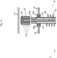
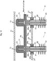
- cross-sectional structure views in Figs. 7 , 12 , 13 , and 16 illustrate not a cross-section but a state in a side surface view as for a resistance wire 61 and heat radiation fin 69 to easily understand the structures.
- the frame 10 houses the resistance unit 20 in an upper stage and the cooling unit 30 in a lower stage. Additionally, the frame 10 has a side portion provided with the connection switching unit 40 and has a lower portion provided with a caster.
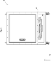
- the frame 10 has a side surface (surface on which a terminal 63 of a resistor R constituting the resistance unit 20 is visible) provided with a cover 11 adapted to protect the terminal 63, a cable or a short-circuit bar connected to the terminal 63, and a casing 21 that holds the resistor R (see Fig. 2 ) .
- the cover 11 is made of a conductive material such as iron or aluminum.
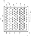
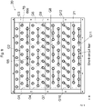
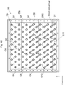
- the resistance unit 20 is obtained by arranging, in a plurality of stages in the z-direction, a resistor row in having a plurality of rod-shaped resistors R arranged in parallel to the y-direction at predetermined intervals in the x-direction, and used to perform, for example, a load test for a test target power source of a power generator or the like connected via a terminal connecting portion 43.
- the resistor R receives power supply from the test target power source.
- the resistor rows each having nine resistors R arranged in the x-direction are arranged in thirteen stages in the z-direction.
- the number of resistors R arranged in each resistor row and the number of stages in which the resistor rows are stacked are not limited to the above.
- resistors R in one resistor row of one stage be used as spare resistors for replacement or the like in the case of failure of another resistor R, and resistors R constituting resistor rows of other stages be used as resistors R constituting a first resistor group G1 to a twelfth resistor group G12.
- resistors R constituting the resistance unit 20 six or twelve resistors R adjacent to each other are set as one resistor group, and a load test is performed while changing the number of resistor groups to which voltage is applied from the test target power source.
- connection inside the resistor group (a connection state of the resistors R inside the resistor group) is changed in accordance with a type of power source subjected to a load test.
- the resistance unit 20 includes the first resistor group G1 to the twelfth resistor group G12.
- the first resistor group G1 (rated capacity: 1 kW) including six resistors R having a rated voltage of 400 V and a rated capacity of 167 kW
- the second resistor group G2 (rated capacity: 2 kW, same in the third resistor group G3) including six resistors R having a rated voltage of 116 V and a rated capacity of 334 W
- the fourth resistor group G4 (rated capacity: 5 kW) including six resistors R having a rated voltage 116 V and a rated capacity 834 W
- the fifth resistor group G5 (rated capacity: 10 kW, same in the sixth resistor group G6) including six resistors R having a rated voltage 116 V and a rated capacity 1.67 kW
- the seventh resistor group G7 (rated capacity: 20 kW, same in the eighth resistor group G8 to twelfth resistor group G12) including
- the resistor R includes the resistance wire 61, the terminals 63 electrically connected to the resistance wire 61 and provided at both ends of the resistance wire 61, and a cylindrical portion 67 adapted to hold the terminals 63 via a first insulation member 65a and to cover the resistance wire 61 and a portion of a side surface of the terminal 63 (portion not exposed to outside from a wall constituting the casing 21) (refer to Figs. 6 , 7 , 11 , and 12 ).
- the side surface of the cylindrical portion 67 is provided with the heat radiation fin 69.
- the terminal 63 of the resistor R is connected to the terminal 63 of another resistor R with a short-circuit bar, and connected to the terminal connecting portion 43 and a relay via a cable.
- the resistor R has a side surface covered with the casing 21 formed of four walls.
- a portion of the resistor R not conductive with the terminal 63 (such as vicinity of both ends of the cylindrical portion 67 holding the terminal 63 via the first insulation member 65a) is held at the wall constituting the casing 21 via a second insulation member 65b.
- Figs. 6 and 11 illustrate end portions of the four resistors R held at the casing 21 and two thereof have terminals 63 connected to each other via the short-circuit bar.
- the first distance d1 is a length capable of providing insulation between the cover 11 and the terminal 63 by separation, and in the case where the load testing apparatus 1 is, for example, provided to perform a load test for a three-phase AC power generator having a rated voltage 400 V, a dimension of each of the components is determined such that the first distance d1 becomes 3 cm or more.
- the casing 21 has an upper surface and a lower surface opened so as to allow cold air from the cooling unit 30 provided at a lower portion flow to an upper portion.
- a portion included in the terminal 63 of the resistor R and projecting and exposed from the wall constituting the casing 21 is covered with a cap (protective cover) 70 made of an insulation member such as rubber.
- the cap 70 includes: a cylindrical portion 71 to cover a side surface of a portion included in the terminal 63 and projecting from the wall constituting the casing 21; and a lid portion 73 provided at one end portion of the cylindrical portion 71 and facing the tip of the terminal 63, and a height of an inner wall of the cylindrical portion 71 (a second distance d2) is equal to a length of the portion included in the terminal 63 and exposed from the wall constituting the casing 21.
- the surface (surface exposed to the outside) of the cylindrical portion 71 be formed in folds-like shapes (include folds 71a) so as to prevent short circuit (conductivity) between the resistor R and the cover 11 caused by electrical connection to accumulated dust (refer to Fig. 13 ) .
- resistors R in each resistor row are arrayed such that resistors R in a resistor row adjacent in the z-direction are arranged in a middle position between the resistors R constituting the resistor row and resistors R adjacent to the resistors R in the x-direction.
- the cooling unit 30 having a cooling fan is provided at a lower portion of the resistance unit 20 (the lower stage of the frame 10).
- the relays provided in the cooling unit 30 and provided in each of the resistor groups of the resistance unit 20 and adapted to control power supply to any of the resistor groups from the test target power source are driven by a power source different from the test target power source (a power source for driving the load testing apparatus) (refer to Fig. 3 ).
- the connection switching unit 40 includes an operating unit 41 and the terminal connecting portion 43 (refer to Figs. 2 , 3 , and 8 ).
- the terminal connecting portion 43 may also be arranged at a position separated from the operating unit 41 (for example, a rear surface of the operating unit 41).
- the operating unit 41 includes a mode changeover switch 41a and resistance changeover switches 41b.
- the mode changeover switch 41a is a rotary type operation switch and used to turn on/off the load testing apparatus 1 and select a type of a test target power source (switch the mode).
- the resistance changeover switches 41b are operation switches of slide type (or toggle type or push button type) and also are switches to perform on/off control for the relay in each of the first resistor group G1 to the twelfth resistor group G12.
- the relay of the first resistor group G1 is made to an on state (conductive state) to obtain a state in which current can flow to the first resistor group G1 from the test target power source connected to the load testing apparatus 1 via the terminal connecting portion 43.
- the terminal connecting portion 43 is a terminal to connect the test target power source, and the test target power source and the first resistor group G1 to twelfth resistor group G12 are made to a connectable state via the terminal connecting portion 43.
- the terminal 63 Since the terminal 63 is separated from the cover 11 by a distance of the first distance d1, insulation between the terminal 63 and the cover 11 may be kept even without coverage with the cap 70 as far as the first distance d1 has a sufficient length and the resistor R is held at a predetermined installation position of the wall constituting the casing 21.
- the resistor R is displaced from the predetermined installation position due to vibration or the like, and one side of the terminal 63 comes close to the cover 11.
- the terminal 63 of the resistor R is covered with the cap 70 made of the insulation member, insulation between the terminal 63 and the cover 11 can be kept even when the one side of the terminals 63 comes close to the cover 11 due to displacement of the installation position.
- a conductive material like aluminum or iron can be used for the cover 11.
- the conductive material is unlikely to cause damages such as cracks compared with the case where the cover is made of a non-conductive material such as wood or plastic.
- dimensions of the respective components be set such that the second distance d2 becomes longer than the first distance d1.
- the cover 11 prevents the cap 70 from being dropped even though the cap 70 nearly comes off from the terminal 63 due to vibration when the cap 70 is attached to the terminal 63 and the cover 11 is attached to the frame 10.
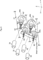
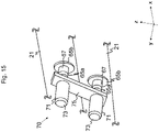
- the description has been provided assuming that only the terminal 63 is covered with the cap 70, but the short-circuit bar adapted to connect terminals 63 adjacent to each other may also be inclusively covered (refer to Figs. 14 to 16 ).
- the cap 70 adapted to cover the short-circuit bar and the terminal 63 includes: a cylindrical portion 71 and the lid portion 73 to cover the terminal 63; and a bar covering portion 75 to cover the short-circuit bar.
- a plurality of sets (two sets in Figs. 14 to 16 ) of the cylindrical portion 71 and the lid portion 73 is provided for one cap 70 so as to cover the plurality of terminals 63 attached with the short-circuit bar.
- the short-circuit bar and the terminals 63 conductive with the resistance wire 61 are covered with the cap 70 made of the insulation member, it is possible to reduce probability that dust is accumulated around the short-circuit bar and the terminal 63 and that short circuit occurs between the resistor R and the cover 11 (that the resistor R becomes conductive with and the cover 11).
- the bar covering portion 75 has a bar rear surface covering portion 75a, which is bent from a portion covering a front surface of the short-circuit bar, adapted to cover a rear surface such that not only a front surface of the short-circuit bar (side facing the cover 11) but also the rear surface (side facing the wall constituting the casing 21) can be covered.
Landscapes
- Physics & Mathematics (AREA)
- General Physics & Mathematics (AREA)
- Engineering & Computer Science (AREA)
- Environmental & Geological Engineering (AREA)
- Health & Medical Sciences (AREA)
- Toxicology (AREA)
- Computer Hardware Design (AREA)
- Microelectronics & Electronic Packaging (AREA)
- General Engineering & Computer Science (AREA)
- Tests Of Circuit Breakers, Generators, And Electric Motors (AREA)
- Testing Electric Properties And Detecting Electric Faults (AREA)
Claims (6)
- Lasttestvorrichtung (1), umfassend:eine Widerstandseinheit (20), welche eine Mehrzahl von Widerständen, welche dazu eingerichtet sind, eine Energiezufuhr von einer Testziel-Energiequelle zu erhalten, und eine Wand umfasst, welche dazu eingerichtet ist, beide Enden jeder der Mehrzahl von Widerständen zu halten;eine Abdeckung (11), welche an einem Rahmen (10) angebracht ist, welcher die Widerstandseinheit (20) hält und dazu eingerichtet ist, die Wand und einen Abschnitt zu schützen, welcher in einem Anschluss (63) des Widerstands umfasst ist und von der Wand vorsteht und von dieser freigelegt ist;
gekennzeichnet durcheine Kappe (70), welche eine Isoliereigenschaft aufweist und an dem Abschnitt angebracht ist, welcher in dem Anschluss (63) des Widerstands umfasst ist und von der Wand vorsteht, wobeidie Abdeckung (11) aus einem leitfähigen Material hergestellt ist, unddie Kappe (70) zwischen der Abdeckung (11) und dem Abschnitt angeordnet ist, welcher in dem Anschluss (63) des Widerstands umfasst ist und von der Wand vorsteht. - Lasttestvorrichtung (1) nach Anspruch 1, wobeidie Kappe (70) einen zylindrischen Abschnitt (71), welcher dazu eingerichtet ist, eine Seitenfläche des Abschnitts abzudecken, welcher in dem Anschluss (63) des Widerstands umfasst ist und von der Wand vorsteht, und einen Deckelabschnitt (73) umfasst, welcher an einem Endabschnitt des zylindrischen Abschnitts (71) bereitgestellt ist, undder zylindrische Abschnitt (71) eine Fläche aufweist, welche Falze umfasst.
- Lasttestvorrichtung (1) nach Anspruch 1, wobei die Kappe (70) einen zylindrischen Abschnitt (71), welcher dazu eingerichtet ist, eine Seitenfläche des Abschnitts abzudecken, welcher in dem Anschluss (63) des Widerstands umfasst ist und von der Wand vorsteht, einen Deckelabschnitt (73), welcher an einem Endabschnitt des zylindrischen Abschnitts (71) bereitgestellt ist, und einen Leisten-Abdeckabschnitt (75) umfasst, welcher dazu eingerichtet ist, wenigstens eine Seite abzudecken, welche in einer Kurzschlussleiste umfasst ist, welche an dem Widerstand angebracht ist, und der Abdeckung (11) zugewandt ist.
- Lasttestvorrichtung (1) nach Anspruch 3, wobei:der Leisten-Abdeckabschnitt (75) einen Hauptabschnitt und einen Leisten-Rückseite-Abdeckabschnitt (75a) umfasst;wobei der Leisten-Rückseite-Abdeckabschnitt (75a) von dem Hauptabschnitt gebogen ist;eine Seite der Kurzschlussleiste der Wand zugewandt ist; undder Leisten-Rückseite-Abdeckabschnitt (75a) die Seite der Kurzschlussleiste abdeckt.
- Lasttestvorrichtung (1) nach Anspruch 1, wobeidie Kappe (70) einen zylindrischen Abschnitt (71) umfasst, welcher dazu eingerichtet ist, eine Seitenfläche des Abschnitts abzudecken, welcher in dem Anschluss (63) des Widerstands umfasst ist und von der Wand vorsteht, und einen Deckelabschnitt (73) umfasst, welcher an einem Endabschnitt des zylindrischen Abschnitts (71) bereitgestellt ist, undeine innere Wand des zylindrischen Abschnitts (71) eine Höhe aufweist, welche gleich einer Länge des Abschnitts ist, welcher in dem Anschluss (63) des Widerstands umfasst ist und von der Wand vorsteht, und welche ebenfalls länger ist als ein erster Abstand, welcher einen Abstand zwischen einer Spitze des Anschlusses (63) des Widerstands, welcher an der Wand angebracht ist, und der Abdeckung (11) repräsentiert, welche an dem Rahmen (10) angebracht ist.
- Lasttestvorrichtung (1) nach Anspruch 5, wobei der erste Abstand 3 cm oder mehr beträgt.
Applications Claiming Priority (2)
| Application Number | Priority Date | Filing Date | Title |
|---|---|---|---|
| JP2015096151A JP5805905B1 (ja) | 2015-05-11 | 2015-05-11 | 負荷試験装置、負荷試験装置のキャップ |
| PCT/JP2016/055155 WO2016181680A1 (ja) | 2015-05-11 | 2016-02-23 | 負荷試験装置、負荷試験装置のキャップ |
Publications (3)
| Publication Number | Publication Date |
|---|---|
| EP3296756A1 EP3296756A1 (de) | 2018-03-21 |
| EP3296756A4 EP3296756A4 (de) | 2018-12-05 |
| EP3296756B1 true EP3296756B1 (de) | 2022-08-03 |
Family
ID=54545725
Family Applications (1)
| Application Number | Title | Priority Date | Filing Date |
|---|---|---|---|
| EP16792406.7A Active EP3296756B1 (de) | 2015-05-11 | 2016-02-23 | Belastungstestvorrichtung |
Country Status (7)
| Country | Link |
|---|---|
| US (1) | US9885756B2 (de) |
| EP (1) | EP3296756B1 (de) |
| JP (1) | JP5805905B1 (de) |
| KR (1) | KR101813874B1 (de) |
| CN (1) | CN107533104B (de) |
| PH (1) | PH12017501931A1 (de) |
| WO (1) | WO2016181680A1 (de) |
Families Citing this family (3)
| Publication number | Priority date | Publication date | Assignee | Title |
|---|---|---|---|---|
| JP7085790B2 (ja) * | 2018-09-18 | 2022-06-17 | 株式会社辰巳菱機 | 負荷抵抗器 |
| CN111665439B (zh) * | 2019-03-05 | 2022-11-22 | 日本电产增成机器装置(浙江)有限公司 | 马达测试用组件 |
| EP4163891A1 (de) * | 2020-06-04 | 2023-04-12 | Tatsumi Ryoki Co., Ltd | Lasttestvorrichtung und kappe für eine lasttestvorrichtung |
Family Cites Families (11)
| Publication number | Priority date | Publication date | Assignee | Title |
|---|---|---|---|---|
| JPS62162306A (ja) * | 1986-01-13 | 1987-07-18 | 松下電器産業株式会社 | 皮膜抵抗器 |
| JPH117853A (ja) * | 1997-06-19 | 1999-01-12 | Tokyo Electric Power Co Inc:The | 限流ユニット及びこれを用いた限流型高圧クランプ碍子 |
| KR100516576B1 (ko) * | 1999-12-02 | 2005-09-22 | 가부시키가이샤다쓰미료키 | 건식부하 시험장치 |
| JP5265264B2 (ja) * | 2008-07-18 | 2013-08-14 | 株式会社辰巳菱機 | 乾式負荷試験装置 |
| JP3160347U (ja) * | 2010-02-16 | 2010-06-24 | 株式会社サンケイ通商 | 負荷試験装置 |
| JP5211198B2 (ja) * | 2011-06-09 | 2013-06-12 | 株式会社辰巳菱機 | 負荷システム |
| CN102412042B (zh) * | 2011-06-15 | 2013-04-24 | 王爱民 | 一种电阻器 |
| CN202975062U (zh) * | 2012-12-13 | 2013-06-05 | 吴江市华诚电子有限公司 | 一种单相大功率非线性负载箱 |
| CN202975291U (zh) * | 2012-12-13 | 2013-06-05 | 吴江市华诚电子有限公司 | 一种负载箱 |
| WO2014192042A1 (ja) * | 2013-05-30 | 2014-12-04 | 株式会社辰巳菱機 | 負荷試験装置 |
| JP5497234B1 (ja) | 2013-08-20 | 2014-05-21 | 株式会社辰巳菱機 | 負荷試験装置 |
-
2015
- 2015-05-11 JP JP2015096151A patent/JP5805905B1/ja active Active
-
2016
- 2016-02-23 EP EP16792406.7A patent/EP3296756B1/de active Active
- 2016-02-23 WO PCT/JP2016/055155 patent/WO2016181680A1/ja not_active Ceased
- 2016-02-23 CN CN201680027138.8A patent/CN107533104B/zh active Active
- 2016-02-23 KR KR1020177029985A patent/KR101813874B1/ko active Active
-
2017
- 2017-07-24 US US15/657,574 patent/US9885756B2/en active Active
- 2017-10-20 PH PH12017501931A patent/PH12017501931A1/en unknown
Also Published As
| Publication number | Publication date |
|---|---|
| US20170322259A1 (en) | 2017-11-09 |
| KR101813874B1 (ko) | 2018-01-04 |
| EP3296756A1 (de) | 2018-03-21 |
| JP2016211974A (ja) | 2016-12-15 |
| CN107533104A (zh) | 2018-01-02 |
| PH12017501931B1 (en) | 2018-03-19 |
| EP3296756A4 (de) | 2018-12-05 |
| JP5805905B1 (ja) | 2015-11-10 |
| CN107533104B (zh) | 2018-06-12 |
| PH12017501931A1 (en) | 2018-03-19 |
| KR20170140198A (ko) | 2017-12-20 |
| WO2016181680A1 (ja) | 2016-11-17 |
| US9885756B2 (en) | 2018-02-06 |
Similar Documents
| Publication | Publication Date | Title |
|---|---|---|
| KR101689646B1 (ko) | 부하 시험기 | |
| JP5265264B2 (ja) | 乾式負荷試験装置 | |
| CN111326872B (zh) | 用于配电系统的导体 | |
| US8711547B2 (en) | Compact bus bar assembly, switching device and power distribution system | |
| KR101553945B1 (ko) | 고체절연 스위치기어 | |
| CN103779518B (zh) | 电池组件和具有该电池组件的机动车辆 | |
| EP2947733B1 (de) | Gasisolierte schaltanlage | |
| HK1225804B (zh) | 负载试验机和负载试验机的连接切换部 | |
| HK1225804A1 (en) | Load tester and connection-selecting unit for load tester | |
| EP2784527B1 (de) | Belastungstestvorrichtung | |
| CN104396106B (zh) | 开关设备以及开关设备的组装方法 | |
| US9885756B2 (en) | Load testing apparatus and cap for load testing apparatus | |
| JP6623833B2 (ja) | 配線モジュール | |
| US7457105B2 (en) | Vacuum switchgear system and kit for system | |
| EP1453164B1 (de) | Schaltvorrichtung und mehrschichtige schaltvorrichtung | |
| US8298018B2 (en) | Cross connection link for switching devices modularly connected on a support member | |
| HK1241978B (en) | Load testing device and cap of load testing device | |
| HK1241978A1 (en) | Load testing device and cap of load testing device | |
| US11257648B2 (en) | Electronic trip device for molded case circuit breaker | |
| JP2010166697A (ja) | テストプラグ端子用仕切カバー | |
| KR20180000846U (ko) | 배전반 | |
| JP2024115039A (ja) | 電池パック | |
| WO2024121973A1 (ja) | 負荷試験装置の蓄電抵抗器、負荷試験装置 | |
| HK1197563B (en) | Load testing machine | |
| HK1225803A1 (en) | Load tester |
Legal Events
| Date | Code | Title | Description |
|---|---|---|---|
| STAA | Information on the status of an ep patent application or granted ep patent |
Free format text: STATUS: THE INTERNATIONAL PUBLICATION HAS BEEN MADE |
|
| PUAI | Public reference made under article 153(3) epc to a published international application that has entered the european phase |
Free format text: ORIGINAL CODE: 0009012 |
|
| STAA | Information on the status of an ep patent application or granted ep patent |
Free format text: STATUS: REQUEST FOR EXAMINATION WAS MADE |
|
| 17P | Request for examination filed |
Effective date: 20170906 |
|
| AK | Designated contracting states |
Kind code of ref document: A1 Designated state(s): AL AT BE BG CH CY CZ DE DK EE ES FI FR GB GR HR HU IE IS IT LI LT LU LV MC MK MT NL NO PL PT RO RS SE SI SK SM TR |
|
| AX | Request for extension of the european patent |
Extension state: BA ME |
|
| DAV | Request for validation of the european patent (deleted) | ||
| DAX | Request for extension of the european patent (deleted) | ||
| A4 | Supplementary search report drawn up and despatched |
Effective date: 20181031 |
|
| RIC1 | Information provided on ipc code assigned before grant |
Ipc: G01R 31/34 20060101AFI20181025BHEP Ipc: G01R 31/40 20140101ALI20181025BHEP Ipc: G01R 31/00 20060101ALI20181025BHEP |
|
| GRAP | Despatch of communication of intention to grant a patent |
Free format text: ORIGINAL CODE: EPIDOSNIGR1 |
|
| STAA | Information on the status of an ep patent application or granted ep patent |
Free format text: STATUS: GRANT OF PATENT IS INTENDED |
|
| INTG | Intention to grant announced |
Effective date: 20220307 |
|
| GRAS | Grant fee paid |
Free format text: ORIGINAL CODE: EPIDOSNIGR3 |
|
| GRAA | (expected) grant |
Free format text: ORIGINAL CODE: 0009210 |
|
| STAA | Information on the status of an ep patent application or granted ep patent |
Free format text: STATUS: THE PATENT HAS BEEN GRANTED |
|
| AK | Designated contracting states |
Kind code of ref document: B1 Designated state(s): AL AT BE BG CH CY CZ DE DK EE ES FI FR GB GR HR HU IE IS IT LI LT LU LV MC MK MT NL NO PL PT RO RS SE SI SK SM TR |
|
| REG | Reference to a national code |
Ref country code: AT Ref legal event code: REF Ref document number: 1509164 Country of ref document: AT Kind code of ref document: T Effective date: 20220815 Ref country code: CH Ref legal event code: EP |
|
| REG | Reference to a national code |
Ref country code: DE Ref legal event code: R096 Ref document number: 602016073985 Country of ref document: DE |
|
| REG | Reference to a national code |
Ref country code: IE Ref legal event code: FG4D |
|
| REG | Reference to a national code |
Ref country code: LT Ref legal event code: MG9D |
|
| REG | Reference to a national code |
Ref country code: NL Ref legal event code: MP Effective date: 20220803 |
|
| PG25 | Lapsed in a contracting state [announced via postgrant information from national office to epo] |
Ref country code: SE Free format text: LAPSE BECAUSE OF FAILURE TO SUBMIT A TRANSLATION OF THE DESCRIPTION OR TO PAY THE FEE WITHIN THE PRESCRIBED TIME-LIMIT Effective date: 20220803 Ref country code: RS Free format text: LAPSE BECAUSE OF FAILURE TO SUBMIT A TRANSLATION OF THE DESCRIPTION OR TO PAY THE FEE WITHIN THE PRESCRIBED TIME-LIMIT Effective date: 20220803 Ref country code: PT Free format text: LAPSE BECAUSE OF FAILURE TO SUBMIT A TRANSLATION OF THE DESCRIPTION OR TO PAY THE FEE WITHIN THE PRESCRIBED TIME-LIMIT Effective date: 20221205 Ref country code: NO Free format text: LAPSE BECAUSE OF FAILURE TO SUBMIT A TRANSLATION OF THE DESCRIPTION OR TO PAY THE FEE WITHIN THE PRESCRIBED TIME-LIMIT Effective date: 20221103 Ref country code: NL Free format text: LAPSE BECAUSE OF FAILURE TO SUBMIT A TRANSLATION OF THE DESCRIPTION OR TO PAY THE FEE WITHIN THE PRESCRIBED TIME-LIMIT Effective date: 20220803 Ref country code: LV Free format text: LAPSE BECAUSE OF FAILURE TO SUBMIT A TRANSLATION OF THE DESCRIPTION OR TO PAY THE FEE WITHIN THE PRESCRIBED TIME-LIMIT Effective date: 20220803 Ref country code: LT Free format text: LAPSE BECAUSE OF FAILURE TO SUBMIT A TRANSLATION OF THE DESCRIPTION OR TO PAY THE FEE WITHIN THE PRESCRIBED TIME-LIMIT Effective date: 20220803 Ref country code: FI Free format text: LAPSE BECAUSE OF FAILURE TO SUBMIT A TRANSLATION OF THE DESCRIPTION OR TO PAY THE FEE WITHIN THE PRESCRIBED TIME-LIMIT Effective date: 20220803 Ref country code: ES Free format text: LAPSE BECAUSE OF FAILURE TO SUBMIT A TRANSLATION OF THE DESCRIPTION OR TO PAY THE FEE WITHIN THE PRESCRIBED TIME-LIMIT Effective date: 20220803 |
|
| REG | Reference to a national code |
Ref country code: AT Ref legal event code: MK05 Ref document number: 1509164 Country of ref document: AT Kind code of ref document: T Effective date: 20220803 |
|
| PG25 | Lapsed in a contracting state [announced via postgrant information from national office to epo] |
Ref country code: PL Free format text: LAPSE BECAUSE OF FAILURE TO SUBMIT A TRANSLATION OF THE DESCRIPTION OR TO PAY THE FEE WITHIN THE PRESCRIBED TIME-LIMIT Effective date: 20220803 Ref country code: IS Free format text: LAPSE BECAUSE OF FAILURE TO SUBMIT A TRANSLATION OF THE DESCRIPTION OR TO PAY THE FEE WITHIN THE PRESCRIBED TIME-LIMIT Effective date: 20221203 Ref country code: HR Free format text: LAPSE BECAUSE OF FAILURE TO SUBMIT A TRANSLATION OF THE DESCRIPTION OR TO PAY THE FEE WITHIN THE PRESCRIBED TIME-LIMIT Effective date: 20220803 Ref country code: GR Free format text: LAPSE BECAUSE OF FAILURE TO SUBMIT A TRANSLATION OF THE DESCRIPTION OR TO PAY THE FEE WITHIN THE PRESCRIBED TIME-LIMIT Effective date: 20221104 |
|
| PG25 | Lapsed in a contracting state [announced via postgrant information from national office to epo] |
Ref country code: SM Free format text: LAPSE BECAUSE OF FAILURE TO SUBMIT A TRANSLATION OF THE DESCRIPTION OR TO PAY THE FEE WITHIN THE PRESCRIBED TIME-LIMIT Effective date: 20220803 Ref country code: RO Free format text: LAPSE BECAUSE OF FAILURE TO SUBMIT A TRANSLATION OF THE DESCRIPTION OR TO PAY THE FEE WITHIN THE PRESCRIBED TIME-LIMIT Effective date: 20220803 Ref country code: DK Free format text: LAPSE BECAUSE OF FAILURE TO SUBMIT A TRANSLATION OF THE DESCRIPTION OR TO PAY THE FEE WITHIN THE PRESCRIBED TIME-LIMIT Effective date: 20220803 Ref country code: CZ Free format text: LAPSE BECAUSE OF FAILURE TO SUBMIT A TRANSLATION OF THE DESCRIPTION OR TO PAY THE FEE WITHIN THE PRESCRIBED TIME-LIMIT Effective date: 20220803 Ref country code: AT Free format text: LAPSE BECAUSE OF FAILURE TO SUBMIT A TRANSLATION OF THE DESCRIPTION OR TO PAY THE FEE WITHIN THE PRESCRIBED TIME-LIMIT Effective date: 20220803 |
|
| PGFP | Annual fee paid to national office [announced via postgrant information from national office to epo] |
Ref country code: FR Payment date: 20230221 Year of fee payment: 8 |
|
| REG | Reference to a national code |
Ref country code: DE Ref legal event code: R097 Ref document number: 602016073985 Country of ref document: DE |
|
| PG25 | Lapsed in a contracting state [announced via postgrant information from national office to epo] |
Ref country code: SK Free format text: LAPSE BECAUSE OF FAILURE TO SUBMIT A TRANSLATION OF THE DESCRIPTION OR TO PAY THE FEE WITHIN THE PRESCRIBED TIME-LIMIT Effective date: 20220803 Ref country code: EE Free format text: LAPSE BECAUSE OF FAILURE TO SUBMIT A TRANSLATION OF THE DESCRIPTION OR TO PAY THE FEE WITHIN THE PRESCRIBED TIME-LIMIT Effective date: 20220803 |
|
| PGFP | Annual fee paid to national office [announced via postgrant information from national office to epo] |
Ref country code: IT Payment date: 20230223 Year of fee payment: 8 |
|
| PLBE | No opposition filed within time limit |
Free format text: ORIGINAL CODE: 0009261 |
|
| STAA | Information on the status of an ep patent application or granted ep patent |
Free format text: STATUS: NO OPPOSITION FILED WITHIN TIME LIMIT |
|
| PG25 | Lapsed in a contracting state [announced via postgrant information from national office to epo] |
Ref country code: AL Free format text: LAPSE BECAUSE OF FAILURE TO SUBMIT A TRANSLATION OF THE DESCRIPTION OR TO PAY THE FEE WITHIN THE PRESCRIBED TIME-LIMIT Effective date: 20220803 |
|
| 26N | No opposition filed |
Effective date: 20230504 |
|
| PG25 | Lapsed in a contracting state [announced via postgrant information from national office to epo] |
Ref country code: SI Free format text: LAPSE BECAUSE OF FAILURE TO SUBMIT A TRANSLATION OF THE DESCRIPTION OR TO PAY THE FEE WITHIN THE PRESCRIBED TIME-LIMIT Effective date: 20220803 |
|
| PG25 | Lapsed in a contracting state [announced via postgrant information from national office to epo] |
Ref country code: MC Free format text: LAPSE BECAUSE OF FAILURE TO SUBMIT A TRANSLATION OF THE DESCRIPTION OR TO PAY THE FEE WITHIN THE PRESCRIBED TIME-LIMIT Effective date: 20220803 |
|
| REG | Reference to a national code |
Ref country code: CH Ref legal event code: PL |
|
| REG | Reference to a national code |
Ref country code: BE Ref legal event code: MM Effective date: 20230228 |
|
| PG25 | Lapsed in a contracting state [announced via postgrant information from national office to epo] |
Ref country code: LU Free format text: LAPSE BECAUSE OF NON-PAYMENT OF DUE FEES Effective date: 20230223 Ref country code: LI Free format text: LAPSE BECAUSE OF NON-PAYMENT OF DUE FEES Effective date: 20230228 Ref country code: CH Free format text: LAPSE BECAUSE OF NON-PAYMENT OF DUE FEES Effective date: 20230228 |
|
| REG | Reference to a national code |
Ref country code: IE Ref legal event code: MM4A |
|
| PG25 | Lapsed in a contracting state [announced via postgrant information from national office to epo] |
Ref country code: IE Free format text: LAPSE BECAUSE OF NON-PAYMENT OF DUE FEES Effective date: 20230223 |
|
| PG25 | Lapsed in a contracting state [announced via postgrant information from national office to epo] |
Ref country code: BE Free format text: LAPSE BECAUSE OF NON-PAYMENT OF DUE FEES Effective date: 20230228 |
|
| PG25 | Lapsed in a contracting state [announced via postgrant information from national office to epo] |
Ref country code: BG Free format text: LAPSE BECAUSE OF FAILURE TO SUBMIT A TRANSLATION OF THE DESCRIPTION OR TO PAY THE FEE WITHIN THE PRESCRIBED TIME-LIMIT Effective date: 20220803 |
|
| PG25 | Lapsed in a contracting state [announced via postgrant information from national office to epo] |
Ref country code: BG Free format text: LAPSE BECAUSE OF FAILURE TO SUBMIT A TRANSLATION OF THE DESCRIPTION OR TO PAY THE FEE WITHIN THE PRESCRIBED TIME-LIMIT Effective date: 20220803 |
|
| PG25 | Lapsed in a contracting state [announced via postgrant information from national office to epo] |
Ref country code: FR Free format text: LAPSE BECAUSE OF NON-PAYMENT OF DUE FEES Effective date: 20240229 |
|
| PG25 | Lapsed in a contracting state [announced via postgrant information from national office to epo] |
Ref country code: FR Free format text: LAPSE BECAUSE OF NON-PAYMENT OF DUE FEES Effective date: 20240229 |
|
| PG25 | Lapsed in a contracting state [announced via postgrant information from national office to epo] |
Ref country code: IT Free format text: LAPSE BECAUSE OF NON-PAYMENT OF DUE FEES Effective date: 20240223 |
|
| REG | Reference to a national code |
Ref country code: DE Ref legal event code: R082 Ref document number: 602016073985 Country of ref document: DE Representative=s name: PLASSERAUD IP GMBH, DE |
|
| PGFP | Annual fee paid to national office [announced via postgrant information from national office to epo] |
Ref country code: DE Payment date: 20250218 Year of fee payment: 10 |
|
| PGFP | Annual fee paid to national office [announced via postgrant information from national office to epo] |
Ref country code: GB Payment date: 20250220 Year of fee payment: 10 |
|
| PG25 | Lapsed in a contracting state [announced via postgrant information from national office to epo] |
Ref country code: CY Free format text: LAPSE BECAUSE OF FAILURE TO SUBMIT A TRANSLATION OF THE DESCRIPTION OR TO PAY THE FEE WITHIN THE PRESCRIBED TIME-LIMIT; INVALID AB INITIO Effective date: 20160223 |
|
| PG25 | Lapsed in a contracting state [announced via postgrant information from national office to epo] |
Ref country code: HU Free format text: LAPSE BECAUSE OF FAILURE TO SUBMIT A TRANSLATION OF THE DESCRIPTION OR TO PAY THE FEE WITHIN THE PRESCRIBED TIME-LIMIT; INVALID AB INITIO Effective date: 20160223 |
|
| PG25 | Lapsed in a contracting state [announced via postgrant information from national office to epo] |
Ref country code: TR Free format text: LAPSE BECAUSE OF FAILURE TO SUBMIT A TRANSLATION OF THE DESCRIPTION OR TO PAY THE FEE WITHIN THE PRESCRIBED TIME-LIMIT Effective date: 20220803 |