EP3294606B1 - Modulare vorrichtung zum koppeln eines magnetsegmentes an zumindest eine achse eines schienenfahrzeuges - Google Patents
Modulare vorrichtung zum koppeln eines magnetsegmentes an zumindest eine achse eines schienenfahrzeuges Download PDFInfo
- Publication number
- EP3294606B1 EP3294606B1 EP16724590.1A EP16724590A EP3294606B1 EP 3294606 B1 EP3294606 B1 EP 3294606B1 EP 16724590 A EP16724590 A EP 16724590A EP 3294606 B1 EP3294606 B1 EP 3294606B1
- Authority
- EP
- European Patent Office
- Prior art keywords
- module
- coupling
- axle
- rail
- rail vehicle
- Prior art date
- Legal status (The legal status is an assumption and is not a legal conclusion. Google has not performed a legal analysis and makes no representation as to the accuracy of the status listed.)
- Active
Links
Images




Classifications
-
- B—PERFORMING OPERATIONS; TRANSPORTING
- B61—RAILWAYS
- B61H—BRAKES OR OTHER RETARDING DEVICES SPECIALLY ADAPTED FOR RAIL VEHICLES; ARRANGEMENT OR DISPOSITION THEREOF IN RAIL VEHICLES
- B61H7/00—Brakes with braking members co-operating with the track
- B61H7/02—Scotch-blocks, skids, or like track-engaging shoes
- B61H7/04—Scotch-blocks, skids, or like track-engaging shoes attached to railway vehicles
- B61H7/06—Skids
- B61H7/08—Skids electromagnetically operated
- B61H7/086—Suspensions therefor
-
- B—PERFORMING OPERATIONS; TRANSPORTING
- B60—VEHICLES IN GENERAL
- B60T—VEHICLE BRAKE CONTROL SYSTEMS OR PARTS THEREOF; BRAKE CONTROL SYSTEMS OR PARTS THEREOF, IN GENERAL; ARRANGEMENT OF BRAKING ELEMENTS ON VEHICLES IN GENERAL; PORTABLE DEVICES FOR PREVENTING UNWANTED MOVEMENT OF VEHICLES; VEHICLE MODIFICATIONS TO FACILITATE COOLING OF BRAKES
- B60T13/00—Transmitting braking action from initiating means to ultimate brake actuator with power assistance or drive; Brake systems incorporating such transmitting means, e.g. air-pressure brake systems
- B60T13/74—Transmitting braking action from initiating means to ultimate brake actuator with power assistance or drive; Brake systems incorporating such transmitting means, e.g. air-pressure brake systems with electrical assistance or drive
- B60T13/748—Transmitting braking action from initiating means to ultimate brake actuator with power assistance or drive; Brake systems incorporating such transmitting means, e.g. air-pressure brake systems with electrical assistance or drive acting on electro-magnetic brakes
-
- B—PERFORMING OPERATIONS; TRANSPORTING
- B61—RAILWAYS
- B61H—BRAKES OR OTHER RETARDING DEVICES SPECIALLY ADAPTED FOR RAIL VEHICLES; ARRANGEMENT OR DISPOSITION THEREOF IN RAIL VEHICLES
- B61H13/00—Actuating rail-vehicle brakes
- B61H13/34—Details
- B61H13/36—Beams; Suspension thereof
-
- F—MECHANICAL ENGINEERING; LIGHTING; HEATING; WEAPONS; BLASTING
- F16—ENGINEERING ELEMENTS AND UNITS; GENERAL MEASURES FOR PRODUCING AND MAINTAINING EFFECTIVE FUNCTIONING OF MACHINES OR INSTALLATIONS; THERMAL INSULATION IN GENERAL
- F16D—COUPLINGS FOR TRANSMITTING ROTATION; CLUTCHES; BRAKES
- F16D63/00—Brakes not otherwise provided for; Brakes combining more than one of the types of groups F16D49/00 - F16D61/00
- F16D63/008—Brakes acting on a linearly moving member
-
- F—MECHANICAL ENGINEERING; LIGHTING; HEATING; WEAPONS; BLASTING
- F16—ENGINEERING ELEMENTS AND UNITS; GENERAL MEASURES FOR PRODUCING AND MAINTAINING EFFECTIVE FUNCTIONING OF MACHINES OR INSTALLATIONS; THERMAL INSULATION IN GENERAL
- F16D—COUPLINGS FOR TRANSMITTING ROTATION; CLUTCHES; BRAKES
- F16D65/00—Parts or details
- F16D65/02—Braking members; Mounting thereof
Definitions
- the present invention relates to a modular device for coupling at least one magnetic segment of a rail brake to at least one axle of a rail vehicle. More particularly, the present invention relates to a magnetic segment carrier for eddy current brakes.
- Rail brakes such as eddy current brakes or magnetic rail brakes are used in particular in high-speed trains.
- the force is in this case transmitted directly between the rail and a frame part (such as the bogie frame) and / or an axis of the rail vehicle.
- the electromagnetic force generated during braking also has a vertical force in addition to the longitudinally acting braking force.
- a segment carrier and a Tragarmkonsole is used, which is designed in conventional systems as a integral support in the form of a monolithic cast steel part.
- the integral carrier combines the functions of the braking force and vertical power transmission to the bogie, the fixation of the magnet systems and the provision of the magnetic yoke.
- the integral carrier for conventional magnetic segment carrier has due to its design a high stability, but is not or hardly adaptable to the specific features of the various rail vehicles. Therefore, the integral beam for each rail vehicle must be manufactured separately and can not be changed after production. If the rail vehicle should change or if further components are to be accommodated in the substructure, a new integral beam must be developed. Since the integral carrier represents a custom-made product for each vehicle type, this procedure is complicated and cost-intensive.
- EP 0 724 997 A1 is a known coupling of a magnet segment to an axis disclosed a rail vehicle.
- the present invention has for its object to provide alternatives for the conventional cast steel carrier or in welded design.
- the present invention relates to a modular device for coupling a magnetic segment of a rail brake to at least one axle of a rail vehicle.
- the modular device comprises the following features: a carrier module for supporting the magnet segment, at least one coupling module for coupling to at least one axis of the rail vehicle and at least one connection module for connecting the carrier module to the at least one coupling module.
- the carrier module, the at least one coupling module and the at least one connecting module are connectable to each other to produce a coupling of the magnet segment to the at least one axis of the rail vehicle, so that a vertically acting force when activating the rail brake from the carrier module to the axis of the rail vehicle is transferable.
- the coupling module may also couple to a lifting device to raise the rail brake (e.g., at deactivation).
- a lifting device to raise the rail brake (e.g., at deactivation).
- the at least one coupling module can couple to a lifting device, which is designed for vertical lifting of the rail brake.
- the carrier module serves as a magnetic segment carrier and at the same time as a protective box for the magnetic coils or for the other magnetic components which serve for braking.
- the at least one coupling module serves as a vertical force transmitter and can optionally represent or comprise a support arm console.
- the rail vehicle comprises at least one wheel for guiding the rail vehicle on a rail, wherein the at least one wheel is fastened to the axle.
- the rail vehicle can also have a first axle with two wheels and a second axle with two wheels, wherein the rail brake is formed between the first axle and the second axle.
- the carrier module has an elongated extension which extends parallel to the rail after attachment to the rail vehicle.
- the at least one coupling module may optionally be designed to couple to the axle on at least one of the two sides of the wheel.
- the coupling module can also couple on both sides of the wheel to the corresponding axis. In other words, the side on which the coupling module couples to the axis is arbitrary and can be selected according to the needs.
- the magnetic segment carrier is not only attached to an axle, but may couple to a plurality of axles in other embodiments. Therefore, the at least one connection module may comprise a first connection module and a second connection module arranged on opposite sides of the support module. Likewise, the at least one coupling module may comprise a first coupling module for coupling the first connection module to the first axis and a second coupling module for coupling the second connection module to the second axis. The first and second coupling module may optionally have the same or a different length so as to allow a symmetrical or offset to one of the two axes support of the carrier module.
- the carrier module makes it possible to arrange the carrier module between the first and second axis so that the available space is optimally utilized. Optional can This also creates additional space for additional components between the corresponding wheels and the carrier module.
- the carrier module with the magnetic coils need not necessarily be formed in the entire space between the axes. For example, if there is a very large distance between the axles, the rail brake may optionally be formed on only one part. It is also possible that on the right side of the rail vehicle, the carrier module is formed at a different location along the direction of movement than on the left side.
- the at least one connection module can also have at least one further connection module and the at least one coupling module at least one further coupling module, so that the carrier module is arranged with the first axis (or with the second axis) at two locations between which one of the wheels is located. can be coupled.
- the further coupling module can couple to the axis in such a way that the occurring torques are minimized during a braking operation, which in turn leads to a reduced material fatigue.
- the carrier module can be mounted vertically movable on the rail vehicle and the at least one coupling module comprise a support arm.
- the support arm may couple to the axle of the rail vehicle to limit the vertical movement of the support module such that a predetermined air gap is maintained between the rail and the magnet segment during braking of the rail brake.
- the support arm may also be formed as an integral part of the at least one coupling module.
- the at least one coupling module may extend with a lateral offset parallel to the carrier module and the at least one connection module may be designed to provide a connection between the one another laterally staggered carrier module and the at least one coupling module produce. Therefore, the at least one connection module may serve as a crank or angle screw connector to achieve the lateral offset between the carrier module (which runs parallel above the rail) and the coupling module (which couples to the axle adjacent to the wheel).
- the device may include a lane-hold module that is attached to the carrier module and configured to form a torque arm.
- a torque arm As already mentioned above can be dispensed with the torque arms or they can be made smaller, for example, if no or only a small torque during a braking operation occurs over several coupling modules.
- the space available for the formation of further coupling modules in a given rail vehicle may be limited, so that it may be advantageous instead to form a tracking module to intercept the torques occurring.
- the carrier module may include one or more magnets of an eddy current brake or a magnetic track brake, and the carrier module may form a protective case for the one or more magnets.
- the number of magnets that are held and protected by the carrier module is largely arbitrary or can be adapted to the circumstances (for example, to achieve a desired braking effect).
- the carrier module may have a cross-section perpendicular to its longitudinal extent and / or a material, so that bending of the carrier module is suppressed during a braking operation of the rail vehicle to maintain a homogeneous air gap between the at least one magnet segment and the rail during the braking operation, without compensation by compensating cylinder (eg by separate ring or bellows) to require.
- the carrier module may comprise a first material
- the coupling module may comprise a second material
- the connection module third material wherein the first material, the second material and the third material are selected to fulfill the functions of the carrier module, the coupling module and the connection module.
- the present invention also relates to a system for supporting magnetic segments of a rail brake for a rail vehicle, the rail vehicle having a first axle with two wheels and a second axle with two wheels.
- the system includes a first modular device as described above attachable to the rail vehicle between the first axis and the second axis above a first rail.
- the system includes a second modular device as described above attachable to the rail vehicle between the first axis and the second axis above a second rail.
- the carrier module of the first modular device and the carrier module of the second modular device can be arranged offset to one another in a direction of movement of the rail vehicle or be of different lengths.
- the present invention also relates to a rail vehicle comprising: a rail brake, in particular an eddy current brake or a magnetic rail brake, with magnet segments, and a system for holding magnet segments.
- the rail vehicle comprises four individual wheels as idler gear sets, which rotate about an axis or axle sections (rotation axis) in each case. Rigid axles with two wheels are thus not necessarily present.
- the aforementioned embodiments offer the particular advantage that the device can be manufactured as a kit and is flexibly adaptable to concrete rail vehicles.
- different coupling or connection modules can be combined with a given carrier module or the position of the carrier module between the individual axes can be variably selected according to the wishes.
- the disadvantages of conventional integral carriers occur in embodiments of the present invention is not on.
- a possible deficiency in the strength of the modular carrier according to the present invention can be compensated for by a suitable choice of material of the individual components.
- the total weight of the carrier module can be reduced by a suitable choice of material. Since material and thus weight savings are becoming increasingly important with increasingly higher speeds of rail vehicles, the conventional cast steel carrier / welded construction is disadvantageous in comparison with the present invention (or its potential for saving is limited).
- Fig. 1 shows a modular device for coupling a magnetic segment of a rail brake to an axle 10 of a rail vehicle with a wheel 20.
- the modular device comprises the following features: a support module 110 for supporting the magnet segment; a coupling module 120 for coupling to at least one axle of the rail vehicle; and a connection module 130 for connecting the carrier module 110 to the coupling module 120.
- the carrier module 110, the coupling module 120 and the connection module 130 are connectable to each other to produce a coupling of the magnet segment to the axis 10 of the rail vehicle, so that a vertical force when activating the Rail brake from the carrier module 110 on the axle 10 and thus on the wheel 20 of the rail vehicle is transferable.
- the support module 110 is to be attached to the rail vehicle so that it is above the rail (not visible). Since the coupling module 120 couples to the axle 10, the connection module 130 is used to achieve cranking and the coupling module 120 is attached laterally (not in the lateral extension direction of the support module 110) to the support module 110.
- the modular device is attached to the rail vehicle so as to be vertically movable. This can be achieved for example via special vertical motion components.
- the modular device and in particular the carrier module 110 is lowered vertically so that the magnet segments move towards the rail.
- the magnet segments are rather held at a predetermined distance above the rail. This predetermined distance should be chosen large enough to avoid inadvertent contact of the magnet segments with the rails (which could lead to the destruction of the magnet segments).
- the distance should be chosen small enough to achieve the most efficient magnetic coupling to the rails.
- the braking forces caused by the rail brake thus have a longitudinal component that decelerates the rail vehicle and a vertical component.
- the longitudinal component is forwarded via a brake force transmission unit, for example, to a frame (eg the bogie frame) of the rail vehicle directly.
- the vertical force components are forwarded via the coupling module 120 and via the connection module 130 to the axis of rotation 10 of the wheel 20.
- coupling between the coupler module 120 and the axle 10 of the rail vehicle is required only upon activation of the rail brake, so that no direct or immediate coupling between the coupler module 120 and the axle 10 is required during normal operation of the rail vehicle (the normal rolling friction forces become thus not additionally increased by the modular device). Rather, the coupling of the coupling module 120 with the axis 10 can only take place at the time of lowering of the carrier module 110 when the rail brake is activated. This can be done, for example, that the at least one coupling module 120 has a corresponding recess which engages with the axis 10 itself or with an element which is connected to the axis, so as to forward a vertical force to the axis 10 or by the axle 10 to be supported.
- the connecting module 130 is designed to be correspondingly stable, i. it provides a strong connection between the coupling module 120 and the support module 110 (e.g., a screw or rivet connection, or the like).
- Fig. 2 shows an embodiment of the modular device, in turn, only one connection module 120 and only one coupling module 130 and the carrier module 110 are formed as a magnetic segment carrier.
- the coupling module 120 is designed as a support arm console and the connection module 130 in the form of a crank and establishes the connection between the support module 110 and the coupling module 120.
- the coupling of the coupling module 130 to the axle 10 must be laterally offset from the carrier module 110, this results in the associated vertical forces generating a torque on the carrier module 110 during a braking operation (eg about the vehicle longitudinal axis, ie the x -Axis, around).
- torque arms are required.
- the shown track holder 140 which is attached to the carrier module 110, may provide such torque arm. This ensures that the carrier module 110 can not rotate around the x-axis or around the y-axis or z-axis during a braking operation.
- the track holder 140 may be connected to another carrier module (in the Fig. 2 not visible), which is provided between opposite wheels running on the second rail track. As will be described below, such a track holder 140 is not necessarily present.
- the embodiment of the Fig. 2 a support arm 125 which is attached to the coupling module 120 or may be part of the coupling module 120.
- the support arm 125 may be an integral part of the coupling module 120.
- the support arm 125 is configured to make a connection or coupling to the axle 10 of the rail vehicle.
- the support arm 125 may be rotatably mounted, for example, in an angular range relative to the coupling module 120 (eg via a bolt holder).
- By setting the angle range it becomes possible to set a predetermined value for a maximum lowering of the carrier module 110.
- Upon reaching the maximum lowering of the support arm reaches a stop (eg by means of a part of the bolt connection), which prevents further lowering. It is thus achieved that the magnet segments in the carrier module 110 are at a predetermined distance from the rail (not shown in FIG Fig. 2 ).
- the predetermined distance is chosen so that an efficient braking by means of the rail brake is made possible.
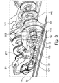
- Fig. 3 shows further optional components.
- the modular device is between a first wheel 21 and a second wheel 22 educated.
- the first wheel 21 is attached to a first axle 11 and the second wheel 22 is attached to a second axle 12.
- the modular device has two coupling modules 121, 122 and two connection modules 131, 132.
- a first coupling module 121 and a first connection module 131 provide the connection from the carrier module 110 to the first axis 11.
- the second coupling module 122 and the second connection module 132 provide a connection from the carrier module 110 to the second axis 12.
- the embodiment of the Fig. 3 a first actuator 201 and a second actuator 202 configured to vertically lower the carrier module 110, such as upon actuation of the brake, so that magnetic segments in the carrier module 110 move toward the rail 30 and at a predetermined distance above the rail 30 are kept.
- the embodiment of the Fig. 3 a first track holder 141 and a second track holder 142, which provide a connection between the carrier module 110 and an opposite carrier module (not shown in FIG Fig. 3 ) produce.
- the first and the second coil holder 141, 142 are designed to hold the carrier module 110 and the further carrier module in a fixed position during a braking operation, so that in particular can not lead to a rotation of the carrier module 110 about an arbitrary axis of rotation. This makes it possible to ensure that all magnet segments remain along the rail track at the predetermined distance, so that efficient braking is ensured.
- the adjusting device 150 is designed to compensate for wear (for example on the wheels with increasing transit time). As already stated, it is important for a reliable functioning of an eddy current brake to maintain a predetermined distance of the magnets from the rail. For example, if the wheels wear over time (ie their radius decreases), the magnet segments should lower less deeply so as to maintain the gap between the rail 30 and the magnet segments at the predetermined constant value. This readjustment can be made by the adjuster 150, which can be adjusted so that the support module 110 when lowering by means of the actuators 201, 202 is lowered only so far that the magnets do not come in direct contact with the rail 30, so as to avoid damage. For the function of a magnetic rail brake, the defined distance can also be zero.
- Fig. 4a-c shows exemplary embodiments of possible suspensions of the support module 110 between a first wheel 21 and a second wheel 22, which are moved on a rail (not shown).
- the first wheel 21 is mounted on a first axle 11 and the second wheel 22 is mounted on a second axle 12.
- a center line M indicates the center position between the first axis 11 and the second axis 12.
- the carrier element 110 can be coupled to the first axis 11 by means of a first coupling module 121, the first coupling module 121 being fastened to the carrier module 110 via a first connecting module 131.
- the carrier module 110 can be coupled to the second axis 12 via a second connection module 132 and a second coupling module 122.
- the first and second connection modules 131, 132 are disposed on opposite sides of the direction of movement of the rail vehicle on the support module 110.
- the support module 110 extends between the first wheel 21 and the second wheel 22 to a maximum possible extent, symmetrical with respect to the center line M.
- the support module 110 extends on a smaller portion between the first wheel 21 and the second wheel 22. Therefore, in the embodiment, the Fig. 4b the first coupling module 121 and the second coupling module 122, for example, of the same length, but have a greater length than the first coupling module 121 and the second coupling module 122 from the Fig. 4a , In the embodiment of the Fig. 4b is a first gap R1 between The support module 110 and the first wheel 11 and a second clearance R2 are formed between the support module 110 and the second wheel 22.
- the first and second gaps R 1, R 2 can be used for other components (not shown).
- the carrier module 110 is not arranged centrally with respect to the center axis M. It is instead shifted to the first wheel 21. Alternatively, it is also possible to move the carrier module 110 toward the second wheel 22. The displacement may be made equal or different on opposite sides of the wheel, that is, on the right side of the rail vehicle, the carrier module 110 may be displaced toward the first axis 11 while being displaced to the left on the second axis 12 (or vice versa). Accordingly, in the embodiment of the Fig. 4c the first coupling module 121 is shorter than the second coupling module 122. In further embodiments, this is reversed, ie, the first coupling module 121 is formed longer than the second coupling module 122nd
- connection modules 121 ', 122' and further coupling modules 131 ', 132' are formed. This ensures that a double-sided coupling of the carrier element 110 to the first axis 11 and / or to the second axis 12 is possible.
- the further connection modules 121 ', 122' may couple between the opposite wheels to the first and / or second axes 11, 12.
- a further first coupling module 121 'and a further first connection module 131' are provided, which effect a coupling between the carrier module 110 and the first axis 11 on one Radaus H- and on a wheel inner side (the other rail track side facing).
- a further second coupling module 122 'and a further second connecting module 132' may be formed to provide a coupling between the carrier module 110 and the second axis 12 to provide, which also takes place at an axis portion which lies between two opposite wheels.
- a two-sided coupling of a wheel axle (i.e., on both sides of the wheel) has the advantage that no or a significantly smaller torque acts on the carrier module during braking or it can be picked up directly from the axle.
- the stresses in the materials are reduced and the track holder 140 is no longer required or can be made much smaller.
- Fig. 5a . b show two possibilities for existing magnet segments and other optional components how the modular device can be attached to a frame.
- the carrier module has a total of 8 magnetic poles, of which four first pole elements 210 (eg, N pole elements) alternately alternate with four second pole elements 220 (eg, S pole elements).
- the pole elements are arranged alternately along the extension direction of the carrier module 110.
- pole elements 210, 220 are arranged alternately along the carrier module 110, namely eight north pole elements and eight south pole elements.
- the number of poles or magnets can be chosen arbitrarily.
- Fig. 5 shown how the carrier module 110 below a frame 80 (eg bogie frame) is arranged and the frame 80 is connected via a spring-loaded suspension 82 to the first axis 11 and the second axis 12 of the rail vehicle.
- the first wheel 21 is in turn attached to the first axle 11 and the second wheel 22 is attached to the second axle 12. It can also be seen how the first wheel 21 and the second wheel 22 are arranged rollably on the rail 30 are.
- the Fig. 6a, b show that the first coupling module 121 may be arranged on a wheel outside (outside the two wheels opposite to each other on an axle) or on a wheel inside (between the two wheels facing one another on an axle).
- the Fig. 6a shows the embodiment where the first coupling module 121 and the second coupling module 122 at a Radau builtseite to the first axis 11 and the second axis 12 couple.
- the embodiment of Fig. 6b shows the possibility that the further first coupling module 121 'on a wheel inner side of the first axis 11 and the further second coupling module unit 122' on a wheel inner side of the second axis 12 couples.
- the first and second coupling modules 121, 122 need not be formed.
- the coupling to the first axis 11 takes place on the radwave side, while the coupling to the second axis 12 takes place on the inside of the wheel (or vice versa).
- the Fig. 7 illustrates the operation of the magnetic force effect, wherein the device is analogous to the embodiment, as shown in the Fig. 5 you can see. A repeated description is therefore not required here.
- the Fig. 7 shows the magnetic brake in a high position, which is left during the braking operation and the support module 110 moves toward the rail 30, until a predetermined air gap 33 between the lower portion of the magnets and the rail 30 is reached.
- the predetermined air gap has, for example, an extension in a range of 5 to 9 mm or in a range between 5 and 15 mm.
- an attraction force is generated by the magnets 210, 220, which may, for example, cause the carrier module 110 to be pulled so strongly toward the rail that it results in a deflection of the carrier module 110 can come. Therefore, it may be necessary that actuation cylinders (which are designed, for example, as air bellows) are present, which make a counter-control as a function of the braking force exerted, so that the air gap 33 is maintained as homogeneously as possible between the carrier module and the rail 30.
- actuation cylinders which are designed, for example, as air bellows
- Embodiments of the present invention now offer the advantage that the cross section of the carrier module 110 or its material can be chosen such that there is no or only a slight bending of the carrier module, so that it is possible to dispense with the annular bellows and still provide sufficient Braking effect and a desired air gap sets.
- the three main assemblies or sub-modules include: the magnetic segment carrier (carrier module 110 as a self-supporting segment carrier), the angle screw connector (connection module 130), and the vertical force transmitter (support arm console or coupling module 120). This provides a flexible and scalable concept solution.
- a Tragarmkonsole 120 can be performed with the support arm 125 as an integrated component.
- the magnet box carrier (the carrier module 110) only partially to equip with magnets.
- the embodiments consider a major trend in the development of new high-speed trains, which consists in a reduction of the axle load.
- the exemplary eddy current brake (ECB) provides an additional mass contribution and increases the axle load of the corresponding swivel chassis (bogie).
- Existing eddy current brakes have a weight to power ratio (at 200 km / h) of about 0.8 kg / kW.
- partial masses of eddy current components should be achievable which allow a weight to power ratio (at 200 km / h) of less than 0.6 kg / kW.
- Another advantage of embodiments is that the new framework concept for a variety of bogies with different center distances and different clearances for the braking device is applicable.
- a fully symmetrical arrangement of magnetic poles or a partially symmetrical arrangement of magnetic poles can be used.
- solenoid coils can be selected depending on the available space between the axes. It is also possible to use an optimized pole spacing of the magnets (since the total length of the carrier module is variable adjustable). Exemplarily, embodiment 8 or 16 include poles or solenoids within a carrier module 110.
- Wirbelstrombremsrahmen on the chassis (Bogie) with an outside bracket and / or with an inside bracket.
- a symmetrical or an asymmetrical arrangement can be chosen freely.
- chassis with outside bracket of the support arm 125 and the Tragarmkonsole 120 is attached to an outside of the wheel.
- the support arm 125 and the Tragarmkonsole 120 is attached to an inner side of the wheel.
Landscapes
- Engineering & Computer Science (AREA)
- Mechanical Engineering (AREA)
- General Engineering & Computer Science (AREA)
- Physics & Mathematics (AREA)
- Electromagnetism (AREA)
- Transportation (AREA)
- Braking Arrangements (AREA)
- Dynamo-Electric Clutches, Dynamo-Electric Brakes (AREA)
Description
- Die vorliegende Erfindung bezieht sich auf eine modulare Vorrichtung zum Koppeln zumindest eines Magnetsegmentes einer Schienenbremse an zumindest eine Achse eines Schienenfahrzeuges. Insbesondere bezieht sich die vorliegende Erfindung auf einen Magnetsegmentträger für Wirbelstrombremsen.
- Insbesondere bei Hochgeschwindigkeitszügen kommen Schienenbremsen wie beispielsweise Wirbelstrombremsen oder Magnetschienenbremsen zum Einsatz. Die Kraftwirkung wird hierbei direkt zwischen der Schiene und einem Rahmenteil (wie beispielsweise dem Drehgestellrahmen) und/oder einer Achse des Schienenfahrzeugs übertragen. Die bei einer Bremsung erzeugte elektromagnetische Kraft weist neben der longitudinal wirkendenden Bremskraft ebenfalls eine Vertikalkraft auf. Für diese Kraftkopplung wird ein Segmentträger und eine Tragarmkonsole genutzt, die bei konventionellen Systemen als ein Integralträger in Form eines monolithischen Stahlgussteils ausgeführt ist. Der Integralträger vereint die Funktionen der Bremskraft- und Vertikalkraft-übertragung zum Drehgestell, der Fixierung der Magnetsysteme und der Bereitstellung des magnetischen Rückschlusses.
- Der Integralträger für konventionelle Magnetsegmentträger weist zwar aufgrund seiner Bauweise eine hohe Stabilität auf, ist aber nicht oder kaum anpassbar an die konkreten Besonderheiten der verschiedenen Schienenfahrzeuge. Daher muss der Integralträger für jedes Schienenfahrzeug separat hergestellt werden und kann nach der Herstellung nicht mehr geändert werden. Wenn sich das Schienenfahrzeug ändern sollte oder wenn im Unterbau weitere Komponenten untergebracht werden sollen, muss ein neuer Integralträger entwickelt werden. Da für jeden Fahrzeugtyp der Integralträger eine Sonderanfertigung darstellt, ist diese Vorgehensweise aufwendig und kostenintensiv.
- In
EP 0 724 997 A1 ist eine bekannte Kopplung eines Magnetsegmentes an eine Achse eines Schienenfahrzeuges offenbart. - Der vorliegenden Erfindung liegt die Aufgabe zugrunde, Alternativen für den konventionellen Stahlgussträger oder in geschweißter Ausführung bereitzustellen.
- Die oben genannte Aufgabe wird durch eine Vorrichtung nach Anspruch 1 gelöst. Die abhängigen Ansprüche beziehen sich auf vorteilhafte Weiterbildungen des Erfindungsgegenstandes.
- Die vorliegende Erfindung bezieht sich auf eine modulare Vorrichtung zum Koppeln eines Magnetsegmentes einer Schienenbremse an zumindest eine Achse eines Schienenfahrzeuges. Die modulare Vorrichtung umfasst die folgenden Merkmale: ein Trägermodul zum Tragen des Magnetsegmentes, zumindest ein Koppelmodul zum Koppeln an zumindest eine Achse des Schienenfahrzeuges und zumindest ein Verbindungsmodul zum Verbinden des Trägermoduls mit dem zumindest einen Koppelmodul. Das Trägermodul, das zumindest eine Koppelmodul und das zumindest eine Verbindungsmodul sind miteinander verbindbar, um eine Kopplung des Magnetsegmentes zu der zumindest einen Achse des Schienenfahrzeuges herzustellen, sodass eine vertikal wirkende Kraft beim Aktivieren der Schienenbremse von dem Trägermodul auf die Achse des Schienenfahrzeuges übertragbar ist. Anstatt an eine Achse kann das Koppelmodul auch an eine Hebeeinrichtung koppeln, um die Schienenbremse anzuheben (z.B. bei einer Deaktivierung). Insbesondere bei Magnetschienenbremsen, bei denen kein vorgegebener Luftspalt zwischen den Magnetsegmenten und der Schiene beim Bremsen erforderlich ist (sie bremsen durch einen direkten Kontakt zur Schiene), kann das zumindest eine Koppelmodul an eine Hebeeinrichtung koppeln, die zum vertikalen Anheben der Schienenbremse ausgebildet ist.
- Somit wird die oben genannte Aufgabe durch den modularen Aufbau gelöst, der eine sehr flexible und skalierbare Konzeptlösung bereitgestellt. Die einzelnen Funktionen sind in separaten Untermodulen verwirklicht. Dabei dient das Trägermodul als ein Magnetsegmentträger und gleichzeitig als ein Schutzkasten für die Magnetspulen oder für die anderen magnetischen Komponenten, die zur Bremsung dienen. Das zumindest eine Koppelmodul dient als Vertikalkraftüberträger und kann optional eine Tragarmkonsole darstellen oder umfassen.
- Das Schienenfahrzeug umfasst zumindest ein Rad zum Führen des Schienenfahrzeuges auf einer Schiene, wobei das zumindest eine Rad an der Achse befestigt ist. Das Schienenfahrzeug kann aber auch eine erste Achse mit zwei Rädern und eine zweite Achse mit zwei Rädern aufweisen, wobei zwischen der ersten Achse und der zweiten Achse die Schienenbremse ausgebildet ist.
- Bei weiteren Ausführungsbeispielen weist das Trägermodul eine längliche Ausdehnung auf, die sich nach einem Anbringen an das Schienenfahrzeug parallel zur Schiene erstreckt. Das zumindest eine Koppelmodul kann optional ausgebildet sein, um an die Achse an zumindest einer der beiden Seiten des Rades zu koppeln. Das Koppelmodul kann aber auch an beiden Seiten des Rades an die entsprechende Achse koppeln. Mit anderen Worten, die Seite, an welcher das Koppelmodul an die Achse koppelt, ist frei wählbar und kann entsprechend den Bedürfnissen ausgewählt werden.
- Im Allgemeinen wird der Magnetsegmentträger jedoch nicht nur an eine Achse befestigt, sondern kann bei weiteren Ausführungsbeispielen an mehreren Achsen koppeln. Daher kann das zumindest eine Verbindungsmodul ein erstes Verbindungsmodul und ein zweites Verbindungsmodul umfassen, die an gegenüberliegenden Seiten des Trägermoduls angeordnet sind. Ebenso kann das zumindest eine Koppelmodul ein erstes Koppelmodul zum Koppeln des ersten Verbindungsmoduls an die erste Achse und ein zweites Koppelmodul zum Koppeln des zweiten Verbindungsmoduls an die zweite Achse umfassen. Das erste und zweite Koppelmodul können optional eine gleiche oder eine unterschiedliche Länge aufweisen, um so eine symmetrische oder eine zu einer der beiden Achsen versetzten Halterung des Trägermoduls zu erlauben.
- Hiermit wird es möglich, das Trägermodul derart zwischen der ersten und zweiten Achse anzuordnen, dass der vorhandene Bauraum optimal ausgenutzt wird. Optional kann hierdurch auch weiterer Platz für weitere Komponenten zwischen den entsprechenden Rädern und dem Trägermodul geschaffen werden. Außerdem braucht nicht notwendigerweise das Trägermodul mit den Magnetspulen in dem gesamten Zwischenraum zwischen den Achsen ausgebildet werden. Wenn beispielsweise ein sehr großer Abstand zwischen den Achsen vorliegt, kann die Schienenbremse optional nur auf einem Teil ausgebildet sein. Ebenso ist es möglich, dass auf der rechten Seite des Schienenfahrzeugs das Trägermodul an einer anderen Stelle entlang der Bewegungsrichtung ausgebildet ist als auf der linken Seite.
- Bei weiteren Ausführungsbeispielen kann das zumindest eine Verbindungsmodul außerdem zumindest ein weiteres Verbindungsmodul und das zumindest eine Koppelmodul zumindest ein weiteres Koppelmodul aufweisen, sodass das Trägermodul mit der ersten Achse (oder mit der zweiten Achse) an zwei Stellen, zwischen denen eines der Räder angeordnet ist, koppelbar ist. Mit einer solchen beidseitigen Kopplung des Koppelmoduls an die Achse wird es möglich, dass ein auftretendes Drehmoment ebenfalls durch die Achse abgestützt werden kann bzw. dass bei einer entsprechend mittigen Anordnung kein Drehmoment auftritt. Dementsprechend kann das weitere Koppelmodul derart an die Achse koppeln, dass die auftretenden Drehmomente bei einem Bremsvorgang minimiert werden, was wiederum zu einer verringerten Materialermüdung führt.
- Bei weiteren Ausführungsbeispielen kann das Trägermodul vertikal beweglich an dem Schienenfahrzeug angebracht sein und das zumindest eine Koppelmodul einen Tragarm umfassen. Der Tragarm kann an die Achse des Schienenfahrzeuges koppeln, um die vertikale Bewegung des Trägermoduls derart zu begrenzen, dass zwischen der Schiene und dem Magnetsegment ein vorbestimmter Luftspalt während eines Bremsvorganges der Schienenbremse aufrechterhalten wird. Bei weiteren Ausführungsbeispielen kann der Tragarm ebenfalls als ein integrales Bauteil des zumindest einen Koppelmoduls ausgebildet sein.
- Bei weiteren Ausführungsbeispielen kann das zumindest eine Koppelmodul sich mit einem lateralen Versatz parallel zu dem Trägermodul erstrecken und das zumindest eine Verbindungsmodul ausgebildet sein, um eine Verbindung zwischen dem lateral zueinander versetzten Trägermodul und dem zumindest einen Koppelmoduls herzustellen. Daher kann das zumindest eine Verbindungsmodul als eine Kröpfung oder ein Winkelschraubverbinder dienen, um den lateralen Versatz zwischen dem Trägermodul (welches parallel oberhalb der Schiene verläuft) und dem Koppelmodul (welches an die Achse neben dem Rad koppelt) zu erreichen.
- Bei weiteren Ausführungsbeispielen kann die Vorrichtung ein Spurhaltemodul aufweisen, das an dem Trägermodul befestigt und ausgebildet ist, um eine Drehmomentstütze zu bilden. Wie oben bereits erwähnt kann auf die Drehmomentstützen verzichtet werden oder sie können kleiner ausgebildet werden, wenn beispielsweise über mehrere Koppelmodule kein oder nur ein geringes Drehmoment während eines Bremsvorganges auftritt. Allerdings kann der vorhandene Bauraum zur Ausbildung weiterer Koppelmodule in einem gegebenen Schienenfahrzeug begrenzt sein, sodass es vorteilhaft sein kann, stattdessen ein Spurhaltemodul auszubilden, um die auftretenden Drehmomente abzufangen.
- Bei weiteren Ausführungsbeispielen kann das Trägermodul eine oder mehrere Magnete einer Wirbelstrombremse oder einer Magnetschienenbremse aufweisen und das Trägermodul kann einen Schutzkasten für den einen oder die mehreren Magnete bilden. Die Anzahl der Magnete, die durch das Trägermodul gehalten und geschützt werden, ist weitestgehend frei wählbar bzw. kann an die Gegebenheiten entsprechend angepasst werden (z.B. um eine gewünschte Bremswirkung zu erreichen).
- Bei weiteren Ausführungsbeispielen kann das Trägermodul einen Querschnitt senkrecht zu seiner Längserstreckung und/oder ein Material aufweisen, sodass während eines Bremsvorganges des Schienenfahrzeuges ein Durchbiegen des Trägermoduls unterdrückt wird, um einen homogenen Luftspalt zwischen dem zumindest einen Magnetsegment und der Schiene während des Bremsvorganges aufrechtzuhalten, ohne einen Ausgleich durch Ausgleichzylinder (z.B. durch separate Ring- oder Luftbälge) zu bedürfen.
- Bei weiteren Ausführungsbeispielen kann das Trägermodul ein erstes Material aufweisen, das Koppelmodul ein zweites Material aufweisen, und das Verbindungsmodul ein drittes Material aufweisen, wobei das erste Material, das zweite Material und das dritte Material ausgewählt sind, um die Funktionen des Trägermoduls, des Koppelmoduls und des Verbindungsmoduls zu erfüllen.
- Die vorliegende Erfindung bezieht sich ebenfalls auf ein System zum Halten von Magnetsegmenten einer Schienenbremse für ein Schienenfahrzeug, wobei das Schienenfahrzeug eine erste Achse mit zwei Rädern und eine zweite Achse mit zwei Rädern aufweist. Das System umfasst eine erste modulare Vorrichtung, wie sie zuvor beschrieben wurde, die zwischen der ersten Achse und der zweiten Achse oberhalb einer ersten Schiene an dem Schienenfahrzeug anbringbar ist. Außerdem umfasst das System eine zweite modulare Vorrichtung, wie sie zuvor beschrieben wurde, die zwischen der ersten Achse und der zweiten Achse oberhalb einer zweiten Schiene an dem Schienenfahrzeug anbringbar ist.
- Optional kann das Trägermodul der ersten modularen Vorrichtung und das Trägermodul der zweiten modularen Vorrichtung in eine Bewegungsrichtung des Schienenfahrzeuges zueinander versetzt angeordnet sein oder unterschiedlich lang sein.
- Die vorliegende Erfindung bezieht sich ebenfalls auf ein Schienenfahrzeug mit: einer Schienenbremse, insbesondere einer Wirbelstrombremse oder einer Magnetschienenbremse, mit Magnetsegmenten, und einem System zum Halten von Magnetsegmenten.
- Bei weiteren Ausführungsbeispielen umfasst das Schienenfahrzeug vier Einzelräder als Losradsätze, die sich um jeweils eine Achse oder Achsabschnitte (Drehachse) drehen. Starre Achsen mit je zwei Rädern sind somit nicht notwendigerweise vorhanden.
- Die genannten Ausführungsbeispiele bieten insbesondere den Vorteil, dass die Vorrichtung als ein Baukasten gefertigt werden kann und an konkrete Schienenfahrzeuge flexibel anpassbar ist. Beispielsweise können verschiedene Koppel- oder Verbindungsmodule mit einem gegebenen Trägermodul kombiniert werden bzw. die Lage des Trägermoduls zwischen den einzelnen Achsen kann variabel entsprechend den Wünschen gewählt werden. Somit treten die Nachteile der konventionellen Integralträger bei Ausführungsbeispielen der vorliegenden Erfindung nicht auf. Ein möglicher Mangel hinsichtlich der Festigkeit des modular aufgebauten Trägers gemäß der vorliegenden Erfindung, kann durch eine geeignete Materialwahl der einzelnen Komponenten kompensiert werden.
- Außerdem kann durch eine geeignete Materialwahl das Gesamtgewicht des Trägermoduls verringert werden. Da mit zunehmend höheren Geschwindigkeiten von Schienenfahrzeugen Material- und somit Gewichtseinsparungen zunehmend an Bedeutung gewinnen, ist der konventionelle Stahlgussträger/Schweißkonstruktion im Vergleich zur vorliegenden Erfindung im Nachteil (bzw. dessen Einsparpotential ist begrenzt).
- Die Ausführungsbeispiele der vorliegenden Erfindung werden besser verstanden von der folgenden detaillierten Beschreibung und den beiliegenden Zeichnungen der unterschiedlichen Ausführungsbeispiele, die jedoch nicht so verstanden werden sollten, dass sie die Offenbarung auf die spezifischen Ausführungsformen einschränkt, sondern lediglich der Erklärung und dem Verständnis dienen.
- Fig. 1
- zeigt eine modulare Vorrichtung gemäß einem Ausführungsbeispiel der vorliegenden Erfindung.
- Fig. 2
- zeigt weitere optionale Komponenten für die modulare Vorrichtung gemäß weiterer Ausführungsbeispiele.
- Fig. 3
- zeigt eine Anbringung der modularen Vorrichtung an einem Schienenfahrzeug zwischen zwei Achsen.
- Fig. 4a-c
- zeigen verschiedene Möglichkeiten einer symmetrischen und asymmetrischen Anordnung des Trägermoduls.
- Fig. 5a-b
- zeigen verschiedene Möglichkeiten hinsichtlich der Anzahl von Magnetsegmenten, die in dem Trägermodul untergebracht sind.
- Fig. 6a-b
- zeigen verschiedene Möglichkeiten der Anbringung des Koppelmoduls an den Achsen des Schienenfahrzeugs.
- Fig. 7
- veranschaulicht die Kraftwirkung während einer Betätigung der Schienenbremse.
-
Fig. 1 zeigt eine modulare Vorrichtung zum Koppeln eines Magnetsegmentes einer Schienenbremse an eine Achse 10 eines Schienenfahrzeuges mit einem Rad 20. Die modulare Vorrichtung umfasst die folgenden Merkmale: ein Trägermodul 110 zum Tragen des Magnetsegmentes; ein Koppelmodul 120 zum Koppeln an zumindest eine Achse des Schienenfahrzeuges; und ein Verbindungsmodul 130 zum Verbinden des Trägermoduls 110 mit dem Koppelmodul 120. Das Trägermodul 110, das Koppelmodul 120 und das Verbindungsmodul 130 sind miteinander verbindbar, um eine Kopplung des Magnetsegmentes zu der Achse 10 des Schienenfahrzeuges herzustellen, sodass eine vertikal wirkende Kraft beim Aktivieren der Schienenbremse von dem Trägermodul 110 auf die Achse 10 und somit auf das Rad 20 des Schienenfahrzeugs übertragbar ist. - Das Trägermodul 110 ist derart an dem Schienenfahrzeug zu befestigen, dass es sich oberhalb der Schiene (nicht zu sehen) befindet. Da das Koppelmodul 120 an die Achse 10 koppelt, wird das Verbindungsmodul 130 genutzt, um eine Kröpfung zu erreichen und das Koppelmodul 120 seitlich (nicht in der lateralen Erstreckungsrichtung des Trägermoduls 110) an dem Trägermodul 110 befestigt ist.
- Die modulare Vorrichtung wird an das Schienenfahrzeug derart befestigt, dass sie vertikal bewegbar ist. Dies kann beispielsweise über spezielle Vertikalbewegungskomponenten erreicht werden. Beim Aktivieren der Schienenbremse wird die modulare Vorrichtung und insbesondere das Trägermodul 110 vertikal abgesenkt, sodass die Magnetsegmente sich auf die Schiene zubewegen. Jedoch kommt es nicht zu einem Kontakt der Magnetsegmente mit den Schienen. Die Magnetsegmente werden vielmehr in einem vorbestimmten Abstand über der Schiene gehalten. Dieser vorbestimmte Abstand sollte groß genug gewählt werden, um einen unbeabsichtigten Kontakt der Magnetsegmente mit den Schienen zu vermeiden (was zu einer Zerstörung der Magnetsegmente führen könnte). Andererseits jedoch sollte der Abstand klein genug gewählt werden, um eine möglichst effiziente magnetische Kopplung zu den Schienen zu erreichen.
- Durch dieses Absenken wird somit ein magnetischer Kontakt zu den Schienen hergestellt und beim Aktivieren werden die Magnetsegmente zur Schiene hin angezogen. Die durch die Schienenbremse verursachten Bremskräfte weisen somit eine Längskomponente, die das Schienenfahrzeug abbremst, und eine vertikale Komponente auf. Die Längskomponente wird über eine Bremskraftübertragungseinheit beispielsweise an einen Rahmen (z.B. den Drehgestellrahmen) des Schienenfahrzeugs direkt weitergeleitet. Die vertikalen Kraftkomponenten werden über das Koppelmodul 120 und über das Verbindungsmodul 130 an die Drehachse 10 des Rades 20 weitergeleitet.
- Daher ist eine Kopplung zwischen dem Koppelmodul 120 und der Achse 10 des Schienenfahrzeugs nur bei der Aktivierung der Schienenbremse erforderlich, so dass keine direkte oder unmittelbare Kopplung zwischen dem Koppelmodul 120 und der Achse 10 während der normalen Fahrweise des Schienenfahrzeugs erforderlich ist (die normalen Rollreibungskräfte werden somit durch die modulare Vorrichtung nicht zusätzlich erhöht). Vielmehr kann die Kopplung des Kopplungsmoduls 120 mit der Achse 10 erst zu dem Zeitpunkt der Absenkung des Trägermoduls 110 bei einem Aktivieren der Schienenbremse erfolgen. Dies kann beispielsweise dadurch geschehen, dass das zumindest eine Koppelmodul 120 eine entsprechende Vertiefung aufweist, die mit der Achse 10 selbst oder mit einem Element, welches mit der Achse verbunden ist, eingreift, um so eine vertikale Kraft an die Achse 10 weiterzuleiten bzw. durch die Achse 10 abgestützt zu werden.
- Damit die bei der Bremsung auftretenden Vertikalkräfte an die Achse 10 zuverlässig weitergeleitet werden können, ist das Verbindungsmodul 130 entsprechend stabil ausgebildet, d.h. es bietet eine belastbare Verbindung zwischen dem Koppelmodul 120 und dem Trägermodul 110 (z.B. eine Schrauben- oder Nietverbindung oder o.ä.).
-
Fig. 2 zeigt ein Ausführungsbeispiel für die modulare Vorrichtung, bei der wiederum nur ein Verbindungsmodul 120 und nur ein Koppelmodul 130 und das Trägermodul 110 als Magnetsegmentträger ausgebildet sind. In dem gezeigten Ausführungsbeispiel ist das Koppelmodul 120 als eine Tragarmkonsole und das Verbindungsmodul 130 in Form einer Kröpfung ausgebildet und stellt die Verbindung zwischen dem Trägermodul 110 und dem Koppelmodul 120 her. - Da die Kopplung des Koppelmoduls 130 an die Achse 10 seitlich versetzt zu dem Trägermodul 110 erfolgen muss, führt dies dazu, dass bei einem Bremsvorgang die damit verbundenen Vertikalkräfte ein Drehmoment auf das Trägermodul 110 erzeugen (z. B. um die Fahrzeuglängsachse, d.h. die x-Achse, herum). Um jedoch eine Verdrehung des Trägermoduls 110 zu vermeiden, sind Drehmomentstützen erforderlich. Beispielsweise kann der gezeigte Spurhalter 140, der an dem Trägermodul 110 befestigt ist, eine solche Drehmomentstütze bieten. Damit wird sicher gestellt, dass das Trägermodul 110 bei einem Bremsvorgang sich weder um die x-Achse herum, noch um die y- oder z-Achse herum drehen kann.
- Beispielsweise kann der Spurhalter 140 zu einem weiteren Trägermodul (in der
Fig. 2 nicht zu sehen) geführt werden, welches zwischen gegenüberliegenden Rädern, die auf dem zweiten Schienenstrang laufen, vorgesehen ist. Wie weiter unten beschrieben wird, ist ein solcher Spurhalter 140 nicht notwendigerweise vorhanden. - Außerdem weist das Ausführungsbeispiel der
Fig. 2 einen Tragarm 125 auf, der an dem Koppelmodul 120 angebracht ist oder ein Teil des Koppelmoduls 120 sein kann. Optional kann der Tragarm 125 integraler Bestandteil des Koppelmoduls 120 sein. Der Tragarm 125 ist ausgebildet, um eine Verbindung oder eine Kopplung zu der Achse 10 des Schienenfahrzeugs herzustellen. Der Tragarm 125 kann beispielsweise in einem Winkelbereich relativ zu dem Koppelmodul 120 drehbar gelagert sein (z.B. über eine Bolzenhalterung). Über die Einstellung des Winkelbereiches wird es möglich, einen vorbestimmten Wert für eine maximale Absenkung des Trägermoduls 110 festzulegen. Beim Erreichen der Maximalabsenkung erreicht der Tragarm einen Anschlag (z.B. mittels eines Teils der Bolzenverbindung), der eine weitere Absenkung verhindert. Damit wird erreicht, dass die Magnetsegmente in dem Trägermodul 110 einen vorbestimmten Abstand zur Schiene (nicht gezeigt inFig. 2 ) einhalten. Der vorbestimmte Abstand ist dabei so gewählt, dass eine effiziente Bremsung mittels der Schienenbremse ermöglicht wird. -
Fig. 3 zeigt weitere optionale Komponenten. In dem gezeigten Ausführungsbeispiel ist die modulare Vorrichtung zwischen einem ersten Rad 21 und einem zweiten Rad 22 ausgebildet. Das erste Rad 21 ist an einer ersten Achse 11 und das zweite Rad 22 ist an einer zweiten Achse 12 befestigt. Außerdem weist die modulare Vorrichtung zwei Koppelmodule 121, 122 und zwei Verbindungsmodule 131, 132 auf. Ein erstes Koppelmodul 121 und ein erstes Verbindungsmodul 131 stellen die Verbindung von dem Trägermodul 110 zu der ersten Achse 11 bereit. Das zweite Koppelmodul 122 und das zweite Verbindungsmodul 132 stellen eine Verbindung von dem Trägermodul 110 zu der zweiten Achse 12 bereit. Außerdem weist das Ausführungsbeispiel derFig. 3 ein erstes Betätigungselement 201 und ein zweites Betätigungselement 202 auf, die ausgebildet sind, um das Trägermodul 110, beispielsweise bei einer Betätigung der Bremse, vertikal abzusenken, sodass Magnetsegmente in dem Trägermodul 110 sich auf die Schiene 30 zubewegen und in einem vorbestimmten Abstand über der Schiene 30 gehalten werden. - Weiter weist das Ausführungsbeispiel der
Fig. 3 einen ersten Spurhalter 141 und einen zweiten Spurhalter 142 auf, die eine Verbindung zwischen dem Trägermodul 110 und einem gegenüberliegenden Trägermodul (nicht gezeigt in derFig. 3 ) herstellen. Der erste und der zweite Spulhalter 141, 142 sind ausgebildet, um das Trägermodul 110 und das weitere Trägermodul bei einem Bremsvorgang positionsfest zu halten, sodass es insbesondere nicht zu einer Verdrehung des Trägermoduls 110 um eine beliebige Drehachse kommen kann. Damit wird erreichbar, dass alle Magnetsegmente entlang des Schienenstranges in dem vorbestimmten Abstand verbleiben, sodass eine effiziente Bremsung sichergestellt ist. - Weiter weist das Ausführungsbeispiel der
Fig. 3 eine Nachstellvorrichtung 150 auf. Die Nachstellvorrichtung 150 ist ausgebildet, um einen Verschleiß (beispielsweise an den Rädern mit zunehmender Laufzeit) zu kompensieren. Wie bereits gesagt, ist es für eine zuverlässige Funktionsweise einer Wirbelstrombremse wichtig, dass ein vorbestimmter Abstand der Magnete von der Schiene eingehalten. Wenn beispielsweise die Räder sich im Laufe der Zeit abnutzen (d.h. dass sich deren Radius verringert), sollen die Magnetsegmente sich weniger tief absenken, um so den Spalt zwischen der Schiene 30 und den Magnetsegmenten auf dem vorbestimmten konstanten Wert zu halten. Diese Nachjustierung kann durch die Nachstellvorrichtung 150 vorgenommen werden, die so eingestellt werden kann, dass das Trägermodul 110 beim Absenken mittels der Betätigungselemente 201, 202 nur soweit abgesenkt wird, dass die Magnete nicht in direktem Kontakt zu der Schiene 30 gelangen, um so Schäden zu vermeiden. Für die Funktion einer Magnetschienenbremse kann der definierte Abstand auch Null sein. -
Fig. 4a-c zeigt Ausführungsbeispiele für mögliche Aufhängungen des Trägermoduls 110 zwischen einem ersten Rad 21 und einem zweiten Rad 22, die auf einer Schiene (nicht gezeigt) bewegt werden. Das erste Rad 21 ist auf einer ersten Achse 11 und das zweite Rad 22 ist auf einer zweiten Achse 12 befestigt. Eine Mittenlinie M zeigt die Mittenposition zwischen der ersten Achse 11 und der zweiten Achse 12 an. - Die drei Ausführungsbeispiele, wie sie in den
Fig. 4 zu sehen sind, unterscheiden sich dadurch, dass das Trägermodul 110 entweder symmetrisch bezüglich der Mittenlinie M angeordnet ist (Ausführungsbeispiele aus denFig. 4a und 4b ) oder asymmetrisch zu der Mittenlinie M angeordnet sind (siehe Ausführungsbeispiel derFig. 4c ). - Bei dem Ausführungsbeispiel der
Fig. 4a ist das Trägerelement 110 mittels eines ersten Koppelmoduls 121 an die erste Achse 11 koppelbar, wobei das erste Koppelmodul 121 über ein erstes Verbindungsmodul 131 an das Trägermodul 110 befestigt ist. Andererseits ist das Trägermodul 110 über ein zweites Verbindungsmodul 132 und ein zweites Koppelmodul 122 an die zweite Achse 12 koppelbar. Das erste und das zweite Verbindungsmodul 131, 132 sind an gegenüberliegenden Seiten bezüglich der Bewegungsrichtung des Schienenfahrzeugs an dem Trägermodul 110 angeordnet. Bei dem Ausführungsbeispiel derFig. 4a erstreckt sich das Trägermodul 110 zwischen dem ersten Rad 21 und dem zweiten Rad 22 auf einer maximal möglichen Ausdehnung, und zwar symmetrisch in Bezug auf die Mittenlinie M. - Bei dem Ausführungsbeispiel der
Fig. 4b erstreckt sich das Trägermodul 110 auf einem geringeren Abschnitt zwischen dem ersten Rad 21 und dem zweiten Rad 22. Daher ist bei dem Ausführungsbeispiel derFig. 4b das erste Koppelmodul 121 und das zweite Koppelmodul 122 beispielsweise gleich lang ausgebildet, aber weisen eine größere Länge auf als das erste Koppelmodul 121 und das zweite Koppelmodul 122 aus derFig. 4a . Bei dem Ausführungsbeispiel derFig. 4b ist ein erster Zwischenraum R1 zwischen dem Trägermodul 110 und dem ersten Rad 11 und ein zweiter Zwischenraum R2 ist zwischen dem Trägermodul 110 und dem zweiten Rad 22 ausgebildet. Der erste und zweite Zwischenraum Rl, R2 können für andere Komponenten (nicht gezeigt) genutzt werden. - Bei dem Ausführungsbeispiel der
Fig. 4c ist das Trägermodul 110 nicht mittig bezüglich der Mittenachse M angeordnet. Es ist stattdessen hin zu dem ersten Rad 21 verschoben. Alternativ ist es ebenfalls möglich, das Trägermodul 110 hin zu dem zweiten Rad 22 zu verschieben. Die Verschiebung kann auf gegenüberliegenden Radseiten gleich oder unterschiedlich vorgenommen werden, d.h. auf der rechten Seite des Schienenfahrzeuges kann das Trägermodul 110 zur ersten Achse 11 verschoben werden, währenddessen es auf der linken Seite hin zu der zweiten Achse 12 verschoben ist (oder umgekehrt). Dementsprechend ist bei dem Ausführungsbeispiel derFig. 4c das erste Koppelmodul 121 kürzer ausgebildet als das zweite Koppelmodul 122. Bei weiteren Ausführungsbeispielen ist dies umgekehrt, d.h. das erste Koppelmodul 121 ist länger ausgebildet als das zweite Koppelmodul 122. - Bei den Ausführungsbeispielen wie sie in den
Fig. 4 zu sehen sind, ist es optional ebenfalls möglich, dass weitere Verbindungsmodule 121', 122' und weitere Koppelmodule 131', 132' ausgebildet sind. Damit wird erreicht, dass eine doppelseitige Kopplung des Trägerelements 110 an die erste Achse 11 und/oder an die zweite Achse 12 möglich wird. Zum Beispiel können die weiteren Verbindungsmodule 121', 122' zwischen den gegenüberliegenden Rädern an die erste und/oder die zweite Achse 11, 12 koppeln. - Diese optionalen weiteren Kopplungselemente 121', 122' sind in der
Fig. 4a bis 4c gestrichelt gezeichnet und können alternative oder als zusätzliche Kopplungen ausgebildet sein. Dementsprechend ist in derFig. 4a optional ein weiteres erstes Koppelmodul 121' und ein weiteres erstes Verbindungsmodul 131' vorhanden, die eine Kopplung zwischen dem Trägermodul 110 und der ersten Achse 11 an einer Radaußen- und an einer Radinnenseite (der dem anderen Schienenstrang zugewandten Seite) bewirken. Optional kann in der gleichen Weise ein weiteres zweites Koppelmodul 122' und ein weiteres zweites Verbindungsmodul 132' ausgebildet sein, um eine Kopplung zwischen dem Trägermodul 110 und der zweiten Achse 12 bereitzustellen, wobei ebenfalls diese Kopplung an einem Achsenabschnitt erfolgt, der zwischen zwei gegenüberliegenden Rädern liegt. - Diese weiteren optionalen Kopplungen können ebenfalls in den Ausführungsbeispielen der
Fig. 4b und 4c ausgebildet werden, was durch die gestrichelten Linien entsprechend dargestellt ist. - Eine beidseitige Kopplung einer Radachse (d.h. auf beiden Seiten des Rades) bietet den Vorteil, dass beim Bremsen kein oder ein deutlich kleineres Drehmoment auf das Trägermodul wirkt bzw. es direkt von der Achse aufgenommen werden kann. Damit werden die Spannungen in den Materialien verringert und der Spurhalter 140 ist nicht mehr erforderlich oder kann deutlich kleiner ausgebildet sein.
-
Fig. 5a ,b zeigen zwei Möglichkeiten für vorhandene Magnetsegmente und weitere optionale Komponenten, wie die modulare Vorrichtung an einem Rahmen befestigt werden kann. - Bei dem Ausführungsbeispiel der
Fig. 5a weist das Trägermodul insgesamt 8 Magnetpole auf, wovon vier erste Pol-Elemente 210 (z.B. N-Pol-Elemente) sich wechselseitig mit vier zweiten Pol-Elementen 220 (z.B. S-Pol-Elemente) abwechseln. Die Pol-Elemente sind entlang der Erstreckungsrichtung des Trägermoduls 110 alternierend angeordnet. - Bei dem Ausführungsbeispiel der
Fig. 5b sind 16 Pol-Elemente 210, 220 alternierend entlang des Trägermoduls 110 angeordnet, und zwar acht Nordpol-Elemente und acht Südpol-Elemente. Die Anzahl der Pole oder Magnete kann beliebig gewählt werden. - Außerdem ist im Ausführungsbeispiel der
Fig. 5 gezeigt, wie das Trägermodul 110 unterhalb eines Rahmens 80 (z.B. Drehgestellrahmen) angeordnet ist und der Rahmen 80 über eine gefederte Radaufhängung 82 mit der ersten Achse 11 und mit der zweiten Achse 12 des Schienenfahrzeuges verbunden ist. Das erste Rad 21 ist wiederum an der ersten Achse 11 und das zweite Rad 22 ist an der zweiten Achse 12 befestigt. Ebenso zu sehen ist, wie das erste Rad 21 und das zweite Rad 22 rollbar auf der Schiene 30 angeordnet sind. - Die
Fig. 6a, b zeigen, dass das erste Koppelmodul 121 auf einer Radaußenseite (außerhalb der beiden auf einer Achse gegenüberliegenden Räder) oder auf einer Radinnenseite (zwischen den beiden auf einer Achse gegenüberliegenden Rädern) angeordnet sein kann. - Die
Fig. 6a zeigt dabei das Ausführungsbeispiel, wo das erste Koppelmodul 121 und das zweite Koppelmodul 122 an einer Radaußenseite an die erste Achse 11 und die zweite Achse 12 koppeln. Das Ausführungsbeispiel derFig. 6b zeigt die Möglichkeit, dass das weitere erste Koppelmodul 121' an einer Radinnenseite der ersten Achse 11 und das weitere zweite Koppelmoduleinheit 122' an einer Radinnenseite der zweiten Achse 12 koppelt. In diesem Beispiel brauchen das erste und zweite Koppelmodul 121, 122 nicht ausgebildet sein. - Bei weiteren Ausführungsbeispielen ist es ebenfalls möglich, dass die Kopplung an die erste Achse 11 radaußerseitig erfolgt, während die Kopplung an die zweite Achse 12 radinnenseitig erfolgt (oder umgekehrt).
- Die
Fig. 7 veranschaulicht die Arbeitsweise der Magnetkraftwirkung, wobei die Vorrichtung analog ist zu dem Ausführungsbeispiel, wie es in derFig. 5 zu sehen ist. Eine wiederholte Beschreibung ist daher hier nicht erforderlich. - Die
Fig. 7 zeigt die Magnetbremse in einer Hochlage, die während des Bremsvorganges verlassen wird und das Trägermodul 110 sich auf die Schiene 30 zu bewegt, und zwar solange, bis ein vorbestimmter Luftspalt 33 zwischen dem unteren Abschnitt der Magnete und der Schiene 30 erreicht ist. Der vorbestimmte Luftspalt hat beispielsweise eine Ausdehnung in einem Bereich von 5 bis 9 mm oder in einem Bereich zwischen 5 und 15 mm. - Nach einem Aktivieren der Magnetbremse, wird eine Anziehungskraft durch die Magnete 210, 220 erzeugt, die beispielsweise dazu führen kann, dass das Trägermodul 110 so stark zur Schiene hingezogen wird, dass es zu einer Verbiegung des Trägermoduls 110 kommen kann. Daher kann es erforderlich sein, dass. Betätigungszylinder (die beispielsweise als Luftbälge ausgebildet sind) vorhanden sind, die eine Gegensteuerung in Abhängigkeit der ausgeübten Bremskraft vornehmen, so dass der Luftspalt 33 möglichst homogen zwischen dem Trägermodul und der Schiene 30 aufrechterhalten wird.
- Da die bisherigen Bremsträger aus Gründen der Gewichtseinsparung und aufgrund ihres Stahlmaterials sich verbogen haben, waren Ringbälge ausgebildet, die pneumatisch eine Entlastung vorgenommen haben, um so den Luftspalt in einer gewünschten Weise einzustellen. Ausführungsbeispiele der vorliegenden Erfindung bieten nun den Vorteil, dass der Querschnitt des Trägermoduls 110 bzw. dessen Material derart gewählt werden kann, dass es zu keiner oder nur zu einer geringen Verbiegung des Trägermoduls kommt, so dass auf die Ringbälge verzichtet werden kann und trotzdem eine ausreichende Bremswirkung und ein gewünschter Luftspalt sich einstellt.
- Wesentliche Aspekte der vorliegenden Erfindung können auch wie folgt zusammengefasst werden.
- Durch eine funktionale Aufteilung des Integralträgers in drei Hauptbaugruppen kann eine funktionsangepasste Auswahl der Materialien und des Herstellungsverfahrens erfolgen. Die drei Hauptbaugruppen oder Untermodule umfassen: den Magnetsegmentträger (Trägermodul 110 als ein selbsttragender Segmentträger), den Winkelschraubverbinder (Verbindungsmodul 130) und den Vertikalkraftüberträger (Tragarmkonsole oder das Koppelmodul 120). Damit wird eine flexible und skalierbare Konzeptlösung bereitgestellt.
- Weitere vorteilhafte Ausgestaltungen bezogen sich darauf, dass eine Tragarmkonsole 120 mit dem Tragarm 125 als ein integriertes Bauteil ausgeführt werden kann. Außerdem war es möglich, die Kröpfung (des Verbindungsmoduls 130) nach innen oder nach außen auszuführen, wobei die konkrete Ausführung der Kröpfung 130 in Abhängigkeit der Position der Radsatzlager erfolgen kann. Ferner ist es gemäß weiteren Ausführungsbeispielen möglich, den Magnetkastenträger (das Trägermodul 110) nur teilweise mit Magneten zu bestücken.
- Somit berücksichtigen die Ausführungsbeispiele einen Haupttrend in der Entwicklung von neuen Hochgeschwindigkeitszügen, der in einer Reduktion der Achslast besteht. Dabei liefert die beispielhafte Wirbelstrombremse (ECB) einen zusätzlichen Massebeitrag und erhöht die Achslast des entsprechenden Drehfahrgestells (Bogie). Insbesondere ist es nicht möglich, die Masse von jeder einzelnen Wirbelstrombremse auf einen gesamten Zug aufzuteilen. Existierende Wirbelstrombremsen haben ein Gewicht-zu-Leistungsverhältnis (bei 200 km/h) von ungefähr 0,8 kg/kW. Wie Analysen gezeigt haben, sollten teilweise Massen von Wirbelstromkomponenten erreichbar sein, die ein Gewicht-zu-Leistungsverhältnis (bei 200 km/h) von weniger als 0,6 kg/kW ermöglichen.
- Bei einer Neugestaltung des Wirbelstrombremsrahmens sollte beachtet werden, dass der Bauraum zur Installation gleich bleibt. Andere Komponenten werden dabei ohne Änderung übernommen (z.B. die Magnetspulen, die Bremskraftübertragungsverbindung, die Luftbälge und der Tragrahmen).
- Ein weiterer Vorteil von Ausführungsbeispielen besteht darin, dass das neue Rahmenkonzept für unterschiedlichste Bogies mit unterschiedlichen Achsabständen und unterschiedlichen Freiräumen für die Bremseinrichtung anwendbar ist. Beispielsweise kann eine vollsymmetrische Anordnung von Magnetpolen oder eine teilweise symmetrische Anordnung von Magnetpolen genutzt werden.
- Die Anzahl der Magnetspulen kann in Abhängigkeit des verfügbaren Raumes zwischen den Achsen gewählt werden. Ebenfalls ist es möglich, einen optimierten Polabstand der Magnete zu nutzen (da die Gesamtlänge des Trägermoduls variable einstellbar ist). Beispielhaft umfassen Aüsführungsbeispiel 8 oder 16 Pole oder Magnetspulen innerhalb eines Trägermoduls 110.
- Es ist weiterhin möglich, den Wirbelstrombremsrahmen auf dem Fahrgestell (Bogie) mit einer außenseitigen Halterung und/oder mit einer innenseitigen Halterung zu installieren. Außerdem kann eine symmetrische oder eine asymmetrischen Anordnung frei gewählt werden. Bei Fahrgestellen mit außenseitiger Halterung wird der Tragarm 125 und die Tragarmkonsole 120 an einer Außenseite des Rades befestigt. Bei einer innenseitigen Halterung wird der Tragarm 125 und die Tragarmkonsole 120 an einer Innenseite des Rades befestigt.
-
- 10
- Achse
- 20, 21, 22
- Räder
- 30
- Schiene
- 33
- Luftspalt
- 80
- Drehgestell
- 82
- gefederte Radaufhängung
- 110
- Trägermodul
- 120, 121, 122, ...
- Koppelmodule
- 120', 121', 122'
- weitere Koppelmodule
- 125
- Tragarm
- 130, 131, 132, ...
- Verbindungsmodule
- 130', 131', 132'
- weitere Verbindungsmodule
- 140
- Spurhalter
- 150
- Nachstellvorrichtung
- 201, 202
- Betätigungselemente
- 210
- erste Magnetpole
- 220
- zweite Magnetpole
- M
- Mittellinie zwischen benachbarten Achsen
Claims (16)
- Modulare Vorrichtung zum Koppeln eines Magnetsegmentes einer Schienenbremse an zumindest eine Achse eines Schienenfahrzeuges, mit folgenden Merkmalen:ein Trägermodul (110) zum Tragen des Magnetsegmentes;zumindest ein Koppelmodul (120) zum Koppeln an zumindest eine Achse des Schienenfahrzeuges oder an eine Hebeeinrichtung; undzumindest ein Verbindungsmodul (130) zum Verbinden des Trägermoduls (110) mit dem zumindest einen Koppelmodul (120),wobei das Trägermodul (110), das zumindest eine Koppelmodul (120) und das zumindest eine Verbindungsmodul (130) miteinander verbindbar sind, um eine Kopplung des Magnetsegmentes zu der zumindest einen Achse (10) des Schienenfahrzeuges herzustellen, sodass eine vertikal wirkende Kraft beim Aktivieren der Schienenbremse von dem Trägermodul (110) auf die Achse (10) übertragbar ist.
- Modulare Vorrichtung nach Anspruch 1, wobei das Schienenfahrzeug zumindest ein Rad (20) zum Führen des Schienenfahrzeuges auf einer Schiene (30) aufweist und das zumindest eine Rad (20) an der Achse (10) befestigt ist,
und wobei das Trägermodul (110) eine längliche Ausdehnung aufweist, die sich nach einem Anbringen an dem Schienenfahrzeug parallel zur Schiene (10) erstreckt und das zumindest eine Koppelmodul (120) ausgebildet ist, um an die Achse (10) an zumindest einer der beiden Seiten des Rades (20) zu koppeln. - Modulare Vorrichtung nach Anspruch 1 oder Anspruch 2, wobei das Schienenfahrzeug eine erste Achse (11) mit zwei Rädern (21) und eine zweite Achse (12) mit zwei Rädern (22) aufweist, und zwischen der ersten Achse (11) und der zweiten Achse (12) die Schienenbremse ausgebildet ist, wobei das zumindest eine Verbindungsmodul (130) ein erstes Verbindungsmodul (131) und ein zweites Verbindungsmodul (132) aufweist, die an gegenüberliegenden Seiten des Trägermoduls (110) angeordnet sind, und das zumindest eine Koppelmodul (120) ein erstes Koppelmodul (121) zum Koppeln des ersten Verbindungsmoduls (131) an die erste Achse (11) und ein zweites Koppelmodul (122) zum Koppeln des zweiten Verbindungsmoduls (132) an die zweite Achse (12) aufweist, und wobei das erste und zweite Koppelmodul (121, 122) eine gleiche oder unterschiedliche Länge aufweisen, um eine symmetrische oder eine zu einer der beiden Achsen versetzten Halterung des Trägermoduls (110) zu erlauben.
- Modulare Vorrichtung nach Anspruch 3, wobei
das zumindest eine Verbindungsmodul (130) außerdem zumindest ein weiteres Verbindungsmodul (130') und das zumindest eine Koppelmodul (120) zumindest ein weiteres Koppelmodul (120') aufweisen, sodass das Trägermodul (110) mit der ersten Achse (11) oder mit der zweiten Achse (12) an zwei Stellen, zwischen denen eines der Räder (20) angeordnet ist, koppelbar ist. - Modulare Vorrichtung nach einem der vorhergehenden Ansprüche, wobei das Trägermodul (110) vertikal beweglich an dem Schienenfahrzeug anbringbar ist und das zumindest eine Koppelmodul (120) einen Tragarm (125) umfasst,
wobei der Tragarm (125) ausgebildet ist, um an die Achse (10) des Schienenfahrzeuges zu koppeln und außerdem die vertikale Bewegung des Trägermoduls (110) derart zu begrenzen, dass zwischen der Schiene (30) und dem Magnetsegment ein vorbestimmter Luftspalt (33) während eines Bremsvorganges der Schienenbremse aufrechterhalten wird. - Modulare Vorrichtung nach Anspruch 5, wobei der Tragarm (125) ein integrales Bauteil des zumindest einen Koppelmoduls (120) ist.
- Modulare Vorrichtung nach einem der vorhergehenden Ansprüche, wobei das zumindest eine Koppelmodul (120) sich mit einem lateralen Versatz parallel zu dem Trägermodul (110) erstreckt und das zumindest eine Verbindungsmodul (130) ausgebildet ist, um eine Verbindung zwischen dem lateral zueinander versetzten Trägermodul (110) und dem zumindest einen Koppelmoduls (120) herzustellen.
- Modulare Vorrichtung nach einem der vorhergehenden Ansprüche, die weiter zumindest ein Spurhaltemodul (140) aufweist, das an dem Trägermodul (110) befestigt ist und ausgebildet ist, um eine Drehmomentstütze zu bilden.
- Modulare Vorrichtung nach einem der vorhergehenden Ansprüche, wobei das Trägermodul (110) ein oder mehrere Magnete einer Wirbelstrombremse oder einer Magnetschienenbremse aufweist und das Trägermodul (110) einen Schutzkasten für das eine oder die mehreren Magnete bildet.
- Modulare Vorrichtung nach einem der vorhergehenden Ansprüche, wobei das Trägermodul (110) einen Querschnitt senkrecht zu seiner Längserstreckung und/oder ein Material aufweist, sodass während eines Bremsvorganges des Schienenfahrzeuges ein Durchbiegen des Trägermoduls (110) unterdrückt wird, um einen homogenen Luftspalt (33) zwischen dem zumindest einen Magnetsegment und der Schiene (30) während des Bremsvorganges aufrechtzuhalten, ohne einen Ausgleich durch Ausgleichzylinder zu bedürfen.
- Modulare Vorrichtung nach einem der vorhergehenden Ansprüche, wobei das Trägermodul (110) ein erstes Material aufweist, das Koppelmodul (120) ein zweites Material aufweist, und das Verbindungsmodul (130) ein drittes Material aufweist und das erste Material, das zweite Material und das dritte Material ausgewählt sind, um die Funktionen des Trägermoduls (110), des Koppelmoduls (120) und des Verbindungsmoduls (130) zu erfüllen.
- Modulare Vorrichtung nach einem der vorhergehenden Ansprüche, wobei die Schienenbremse eine Magnetschienenbremse ist und die Hebeeinrichtung ausgebildet ist, um das Trägermodul (110) beim Deaktivieren der Magnetschienenbremse anzuheben.
- System zum Halten von Magnetsegmenten einer Schienenbremse für ein Schienenfahrzeug, das eine erste Achse (11) mit zwei Rädern (31) und eine zweite Achse (12) mit zwei Rädern (32) aufweist, wobei das System Folgendes umfasst:eine erste modulare Vorrichtung nach einem der Ansprüche 1 bis 12, die zwischen der ersten Achse (11) und der zweiten Achse (12) oberhalb einer ersten Schiene an dem Schienenfahrzeug anbringbar ist; undeine zweite modulare Vorrichtung nach einem der Ansprüche 1 bis 12, die zwischen der ersten Achse (11) und der zweiten Achse (12) oberhalb einer zweiten Schiene an dem Schienenfahrzeug anbringbar ist.
- System nach Anspruch 13, wobei das Trägermodul (110) der ersten modularen Vorrichtung und das Trägermodul (110) der zweiten modularen Vorrichtung in eine Bewegungsrichtung des Schienenfahrzeuges zueinander versetzt angeordnet sind oder unterschiedlich lang sind.
- Schienenfahrzeug mit:einer Schienenbremse, insbesondere einer Wirbelstrombremse oder einer Magnetschienenbremse, mit Magnetsegmenten; undeinem System nach Anspruch 13 oder Anspruch 14.
- Schienenfahrzeug nach Anspruch 15, das weiter vier Einzelräder als Losradsätze umfasst.
Applications Claiming Priority (2)
| Application Number | Priority Date | Filing Date | Title |
|---|---|---|---|
| DE102015107346.3A DE102015107346A1 (de) | 2015-05-11 | 2015-05-11 | Modulare Vorrichtung zum Koppeln eines Magnetsegmentes an zumindest eine Achse eines Schienenfahrzeuges |
| PCT/EP2016/000756 WO2016180528A1 (de) | 2015-05-11 | 2016-05-10 | Modulare vorrichtung zum koppeln eines magnetsegmentes an zumindest eine achse eines schienenfahrzeuges |
Publications (2)
| Publication Number | Publication Date |
|---|---|
| EP3294606A1 EP3294606A1 (de) | 2018-03-21 |
| EP3294606B1 true EP3294606B1 (de) | 2019-02-27 |
Family
ID=56072286
Family Applications (1)
| Application Number | Title | Priority Date | Filing Date |
|---|---|---|---|
| EP16724590.1A Active EP3294606B1 (de) | 2015-05-11 | 2016-05-10 | Modulare vorrichtung zum koppeln eines magnetsegmentes an zumindest eine achse eines schienenfahrzeuges |
Country Status (5)
| Country | Link |
|---|---|
| EP (1) | EP3294606B1 (de) |
| JP (1) | JP6625666B2 (de) |
| CN (1) | CN107635841B (de) |
| DE (1) | DE102015107346A1 (de) |
| WO (1) | WO2016180528A1 (de) |
Families Citing this family (6)
| Publication number | Priority date | Publication date | Assignee | Title |
|---|---|---|---|---|
| CH713901A1 (de) * | 2017-06-20 | 2018-12-28 | Rhaetische Bahn Ag | Drehgestellanbau mit Magnetschienenbremse für ein Schienenfahrzeug. |
| CN107628060A (zh) * | 2017-09-14 | 2018-01-26 | 中车青岛四方车辆研究所有限公司 | 轨道列车用涡流制动器及轨道列车 |
| CN107554550A (zh) * | 2017-09-14 | 2018-01-09 | 中车青岛四方车辆研究所有限公司 | 轨道列车用涡流制动器及轨道列车 |
| CN107539335A (zh) * | 2017-09-14 | 2018-01-05 | 中车青岛四方车辆研究所有限公司 | 轨道列车用涡流制动器及轨道列车 |
| WO2020026913A1 (ja) * | 2018-07-30 | 2020-02-06 | 日本製鉄株式会社 | 渦電流式レールブレーキ装置 |
| CN114228770A (zh) * | 2022-01-20 | 2022-03-25 | 中车长春轨道客车股份有限公司 | 一种安装涡流制动机构的构架装置 |
Family Cites Families (17)
| Publication number | Priority date | Publication date | Assignee | Title |
|---|---|---|---|---|
| US2270425A (en) * | 1940-11-28 | 1942-01-20 | Westinghouse Air Brake Co | Traction increaser apparatus |
| US3506862A (en) * | 1966-07-15 | 1970-04-14 | Japan National Railway | Dynamic and eddy current railway brake device |
| FR1559018A (de) * | 1967-12-28 | 1969-03-07 | ||
| FR2159772A5 (de) * | 1971-11-12 | 1973-06-22 | Creusot Loire | |
| DE2443832A1 (de) * | 1974-09-13 | 1976-03-25 | Knorr Bremse Gmbh | Aufhaengevorrichtung fuer schienenbremsmagnete |
| FR2314852A1 (fr) * | 1975-06-18 | 1977-01-14 | Sncf | Systeme de suspension de frein lineaire a courants de foucault pour vehicule ferroviaire |
| ATE164130T1 (de) * | 1995-02-02 | 1998-04-15 | Knorr Bremse Systeme | Aufhängung einer schienenbremse, insbesondere wirbelstrombremse, an einem drehgestell eines schienenfahrzeuges |
| DE19503381C2 (de) * | 1995-02-02 | 1998-10-29 | Knorr Bremse Systeme | Aufhängung einer Schienenbremse an einem Drehgestell eines Schienenfahrzeuges |
| DE19619578A1 (de) * | 1996-05-15 | 1997-11-20 | Knorr Bremse Systeme | Aufhängung einer Wirbelstrombremse an einem Drehgestell eines Schienenfahrzeuges |
| DE19732482A1 (de) * | 1997-07-29 | 1999-02-04 | Sab Wabco Bsi Verkehrstechnik | Magnetische Bremseinrichtung für Schienenfahrzeuge |
| JP4119103B2 (ja) * | 2001-07-12 | 2008-07-16 | 財団法人鉄道総合技術研究所 | 鉄道車両用輪重制御装置及び方法 |
| DE10154775A1 (de) * | 2001-11-08 | 2003-05-22 | Knorr Bremse Systeme | Magnetspulenanordnung für Schienenfahrzeuge zur Verbesserung der Traktion |
| DE102004018010B3 (de) * | 2004-04-14 | 2005-10-20 | Knorr Bremse Systeme | Magnetschienenbremsvorrichtung |
| JP4431061B2 (ja) * | 2005-01-21 | 2010-03-10 | 財団法人鉄道総合技術研究所 | 脱線防止装置 |
| FR2967635B1 (fr) * | 2010-11-22 | 2012-12-28 | Alstom Transport Sa | Bogie de vehicule ferroviaire comprenant un dispositif de freinage a courants de foucault |
| DE102012014158B4 (de) * | 2012-07-18 | 2014-04-30 | Deutsche Bahn Ag | Verfahren zur Überprüfung von Magnetschienenbremsen und Wirbelstrombremsen für Schienenfahrzeuge sowie Vorrichtungen zur Durchführung der Verfahren |
| WO2016015759A1 (fr) * | 2014-07-30 | 2016-02-04 | Gravity Transport System S.A. | Système de freinage de véhicule sur rail |
-
2015
- 2015-05-11 DE DE102015107346.3A patent/DE102015107346A1/de not_active Ceased
-
2016
- 2016-05-10 CN CN201680027120.8A patent/CN107635841B/zh active Active
- 2016-05-10 WO PCT/EP2016/000756 patent/WO2016180528A1/de not_active Ceased
- 2016-05-10 JP JP2017558974A patent/JP6625666B2/ja active Active
- 2016-05-10 EP EP16724590.1A patent/EP3294606B1/de active Active
Non-Patent Citations (1)
| Title |
|---|
| None * |
Also Published As
| Publication number | Publication date |
|---|---|
| DE102015107346A1 (de) | 2016-11-17 |
| JP6625666B2 (ja) | 2019-12-25 |
| JP2018515385A (ja) | 2018-06-14 |
| EP3294606A1 (de) | 2018-03-21 |
| CN107635841A (zh) | 2018-01-26 |
| CN107635841B (zh) | 2020-03-03 |
| WO2016180528A1 (de) | 2016-11-17 |
Similar Documents
| Publication | Publication Date | Title |
|---|---|---|
| WO2016180528A1 (de) | Modulare vorrichtung zum koppeln eines magnetsegmentes an zumindest eine achse eines schienenfahrzeuges | |
| EP2218662A2 (de) | Hubbalkenförderer | |
| DE102012010316A1 (de) | Reibrollenplanetengetriebe sowie Übersetzungs- und Ausgleichsgetriebe | |
| EP2517905A1 (de) | Federungsanordnung für Radaufhängungen von Kraftfahrzeugen | |
| DE2825176A1 (de) | Aufhaengung fuer voneinander unabhaengige fahrzeugraeder | |
| EP2841318B1 (de) | Vorrichtung zur kraftübertragung zwischen fahrwerk und wagenkasten eines schienenfahrzeugs | |
| EP1161356A1 (de) | Stabilisatoranordnung für das fahrwerk eines fahrzeuges | |
| EP3040219A2 (de) | Modulares niederflurtransportsystem | |
| EP3820798B1 (de) | Transportsystem und transportvorrichtung | |
| EP2195186A2 (de) | Magnetschwebefahrzeug und verfahren zum anheben und/oder absetzen desselben | |
| DE2730963A1 (de) | Scheibenbremse fuer fahrzeuge | |
| DE202015008095U1 (de) | Tandemachse | |
| EP3253637B1 (de) | Transportvorrichtung für schienenfahrzeuge | |
| DE102013004951B4 (de) | Radaufhängung für ein Fahrzeug | |
| EP3451516B1 (de) | Wirkungsveränderliche wirbelstrombremse mit magnetanordnung und induktionsanordnung sowie magnetanordnung und induktionsanordnung hierfür | |
| WO2010040157A1 (de) | Portalkran | |
| EP0800016A2 (de) | Schaltbare, bremswirksame oder kupplungswirksame Vorrichtung, wie eine Reibungsbremse oder eine Reibungskupplung | |
| DE102006042138A1 (de) | Magnetschwebefahrzeug mit Führmagneten | |
| EP3191326B1 (de) | Achseinheit | |
| WO2021239185A1 (de) | Werkstückträgersystem | |
| DE102009039109A1 (de) | Sattelbremse für ein Schienenfahrzeug mit elastischer Bremssattelaufhängung | |
| DE102024104224B3 (de) | Bremseinrichtung für eine Bergbaumaschine | |
| DE102013001474A1 (de) | Teleskopierbare Schiebeholmvorrichtung und Verfahren zu deren Nutzung | |
| DE102011103833B4 (de) | Schienenfahrzeug mit einem Bremssystem | |
| DE102017214235B3 (de) | Kopplungsvorrichtung |
Legal Events
| Date | Code | Title | Description |
|---|---|---|---|
| STAA | Information on the status of an ep patent application or granted ep patent |
Free format text: STATUS: THE INTERNATIONAL PUBLICATION HAS BEEN MADE |
|
| PUAI | Public reference made under article 153(3) epc to a published international application that has entered the european phase |
Free format text: ORIGINAL CODE: 0009012 |
|
| STAA | Information on the status of an ep patent application or granted ep patent |
Free format text: STATUS: REQUEST FOR EXAMINATION WAS MADE |
|
| 17P | Request for examination filed |
Effective date: 20171211 |
|
| AK | Designated contracting states |
Kind code of ref document: A1 Designated state(s): AL AT BE BG CH CY CZ DE DK EE ES FI FR GB GR HR HU IE IS IT LI LT LU LV MC MK MT NL NO PL PT RO RS SE SI SK SM TR |
|
| AX | Request for extension of the european patent |
Extension state: BA ME |
|
| DAV | Request for validation of the european patent (deleted) | ||
| DAX | Request for extension of the european patent (deleted) | ||
| GRAP | Despatch of communication of intention to grant a patent |
Free format text: ORIGINAL CODE: EPIDOSNIGR1 |
|
| STAA | Information on the status of an ep patent application or granted ep patent |
Free format text: STATUS: GRANT OF PATENT IS INTENDED |
|
| INTG | Intention to grant announced |
Effective date: 20180918 |
|
| GRAS | Grant fee paid |
Free format text: ORIGINAL CODE: EPIDOSNIGR3 |
|
| GRAA | (expected) grant |
Free format text: ORIGINAL CODE: 0009210 |
|
| STAA | Information on the status of an ep patent application or granted ep patent |
Free format text: STATUS: THE PATENT HAS BEEN GRANTED |
|
| AK | Designated contracting states |
Kind code of ref document: B1 Designated state(s): AL AT BE BG CH CY CZ DE DK EE ES FI FR GB GR HR HU IE IS IT LI LT LU LV MC MK MT NL NO PL PT RO RS SE SI SK SM TR |
|
| REG | Reference to a national code |
Ref country code: GB Ref legal event code: FG4D Free format text: NOT ENGLISH |
|
| REG | Reference to a national code |
Ref country code: CH Ref legal event code: EP |
|
| REG | Reference to a national code |
Ref country code: DE Ref legal event code: R096 Ref document number: 502016003566 Country of ref document: DE |
|
| REG | Reference to a national code |
Ref country code: AT Ref legal event code: REF Ref document number: 1100887 Country of ref document: AT Kind code of ref document: T Effective date: 20190315 |
|
| REG | Reference to a national code |
Ref country code: IE Ref legal event code: FG4D Free format text: LANGUAGE OF EP DOCUMENT: GERMAN |
|
| REG | Reference to a national code |
Ref country code: CH Ref legal event code: NV Representative=s name: ISLER AND PEDRAZZINI AG, CH |
|
| REG | Reference to a national code |
Ref country code: SE Ref legal event code: TRGR |
|
| REG | Reference to a national code |
Ref country code: NL Ref legal event code: FP |
|
| REG | Reference to a national code |
Ref country code: LT Ref legal event code: MG4D |
|
| PG25 | Lapsed in a contracting state [announced via postgrant information from national office to epo] |
Ref country code: PT Free format text: LAPSE BECAUSE OF FAILURE TO SUBMIT A TRANSLATION OF THE DESCRIPTION OR TO PAY THE FEE WITHIN THE PRESCRIBED TIME-LIMIT Effective date: 20190627 Ref country code: NO Free format text: LAPSE BECAUSE OF FAILURE TO SUBMIT A TRANSLATION OF THE DESCRIPTION OR TO PAY THE FEE WITHIN THE PRESCRIBED TIME-LIMIT Effective date: 20190527 Ref country code: FI Free format text: LAPSE BECAUSE OF FAILURE TO SUBMIT A TRANSLATION OF THE DESCRIPTION OR TO PAY THE FEE WITHIN THE PRESCRIBED TIME-LIMIT Effective date: 20190227 Ref country code: LT Free format text: LAPSE BECAUSE OF FAILURE TO SUBMIT A TRANSLATION OF THE DESCRIPTION OR TO PAY THE FEE WITHIN THE PRESCRIBED TIME-LIMIT Effective date: 20190227 |
|
| PG25 | Lapsed in a contracting state [announced via postgrant information from national office to epo] |
Ref country code: IS Free format text: LAPSE BECAUSE OF FAILURE TO SUBMIT A TRANSLATION OF THE DESCRIPTION OR TO PAY THE FEE WITHIN THE PRESCRIBED TIME-LIMIT Effective date: 20190627 Ref country code: BG Free format text: LAPSE BECAUSE OF FAILURE TO SUBMIT A TRANSLATION OF THE DESCRIPTION OR TO PAY THE FEE WITHIN THE PRESCRIBED TIME-LIMIT Effective date: 20190527 Ref country code: GR Free format text: LAPSE BECAUSE OF FAILURE TO SUBMIT A TRANSLATION OF THE DESCRIPTION OR TO PAY THE FEE WITHIN THE PRESCRIBED TIME-LIMIT Effective date: 20190528 Ref country code: HR Free format text: LAPSE BECAUSE OF FAILURE TO SUBMIT A TRANSLATION OF THE DESCRIPTION OR TO PAY THE FEE WITHIN THE PRESCRIBED TIME-LIMIT Effective date: 20190227 Ref country code: LV Free format text: LAPSE BECAUSE OF FAILURE TO SUBMIT A TRANSLATION OF THE DESCRIPTION OR TO PAY THE FEE WITHIN THE PRESCRIBED TIME-LIMIT Effective date: 20190227 Ref country code: RS Free format text: LAPSE BECAUSE OF FAILURE TO SUBMIT A TRANSLATION OF THE DESCRIPTION OR TO PAY THE FEE WITHIN THE PRESCRIBED TIME-LIMIT Effective date: 20190227 |
|
| PG25 | Lapsed in a contracting state [announced via postgrant information from national office to epo] |
Ref country code: CZ Free format text: LAPSE BECAUSE OF FAILURE TO SUBMIT A TRANSLATION OF THE DESCRIPTION OR TO PAY THE FEE WITHIN THE PRESCRIBED TIME-LIMIT Effective date: 20190227 Ref country code: RO Free format text: LAPSE BECAUSE OF FAILURE TO SUBMIT A TRANSLATION OF THE DESCRIPTION OR TO PAY THE FEE WITHIN THE PRESCRIBED TIME-LIMIT Effective date: 20190227 Ref country code: SK Free format text: LAPSE BECAUSE OF FAILURE TO SUBMIT A TRANSLATION OF THE DESCRIPTION OR TO PAY THE FEE WITHIN THE PRESCRIBED TIME-LIMIT Effective date: 20190227 Ref country code: ES Free format text: LAPSE BECAUSE OF FAILURE TO SUBMIT A TRANSLATION OF THE DESCRIPTION OR TO PAY THE FEE WITHIN THE PRESCRIBED TIME-LIMIT Effective date: 20190227 Ref country code: DK Free format text: LAPSE BECAUSE OF FAILURE TO SUBMIT A TRANSLATION OF THE DESCRIPTION OR TO PAY THE FEE WITHIN THE PRESCRIBED TIME-LIMIT Effective date: 20190227 Ref country code: EE Free format text: LAPSE BECAUSE OF FAILURE TO SUBMIT A TRANSLATION OF THE DESCRIPTION OR TO PAY THE FEE WITHIN THE PRESCRIBED TIME-LIMIT Effective date: 20190227 Ref country code: AL Free format text: LAPSE BECAUSE OF FAILURE TO SUBMIT A TRANSLATION OF THE DESCRIPTION OR TO PAY THE FEE WITHIN THE PRESCRIBED TIME-LIMIT Effective date: 20190227 |
|
| REG | Reference to a national code |
Ref country code: DE Ref legal event code: R097 Ref document number: 502016003566 Country of ref document: DE |
|
| PG25 | Lapsed in a contracting state [announced via postgrant information from national office to epo] |
Ref country code: PL Free format text: LAPSE BECAUSE OF FAILURE TO SUBMIT A TRANSLATION OF THE DESCRIPTION OR TO PAY THE FEE WITHIN THE PRESCRIBED TIME-LIMIT Effective date: 20190227 Ref country code: SM Free format text: LAPSE BECAUSE OF FAILURE TO SUBMIT A TRANSLATION OF THE DESCRIPTION OR TO PAY THE FEE WITHIN THE PRESCRIBED TIME-LIMIT Effective date: 20190227 |
|
| PLBE | No opposition filed within time limit |
Free format text: ORIGINAL CODE: 0009261 |
|
| STAA | Information on the status of an ep patent application or granted ep patent |
Free format text: STATUS: NO OPPOSITION FILED WITHIN TIME LIMIT |
|
| PG25 | Lapsed in a contracting state [announced via postgrant information from national office to epo] |
Ref country code: MC Free format text: LAPSE BECAUSE OF FAILURE TO SUBMIT A TRANSLATION OF THE DESCRIPTION OR TO PAY THE FEE WITHIN THE PRESCRIBED TIME-LIMIT Effective date: 20190227 |
|
| 26N | No opposition filed |
Effective date: 20191128 |
|
| PG25 | Lapsed in a contracting state [announced via postgrant information from national office to epo] |
Ref country code: SI Free format text: LAPSE BECAUSE OF FAILURE TO SUBMIT A TRANSLATION OF THE DESCRIPTION OR TO PAY THE FEE WITHIN THE PRESCRIBED TIME-LIMIT Effective date: 20190227 Ref country code: LU Free format text: LAPSE BECAUSE OF NON-PAYMENT OF DUE FEES Effective date: 20190510 |
|
| PG25 | Lapsed in a contracting state [announced via postgrant information from national office to epo] |
Ref country code: TR Free format text: LAPSE BECAUSE OF FAILURE TO SUBMIT A TRANSLATION OF THE DESCRIPTION OR TO PAY THE FEE WITHIN THE PRESCRIBED TIME-LIMIT Effective date: 20190227 |
|
| PG25 | Lapsed in a contracting state [announced via postgrant information from national office to epo] |
Ref country code: IE Free format text: LAPSE BECAUSE OF NON-PAYMENT OF DUE FEES Effective date: 20190510 |
|
| PG25 | Lapsed in a contracting state [announced via postgrant information from national office to epo] |
Ref country code: CY Free format text: LAPSE BECAUSE OF FAILURE TO SUBMIT A TRANSLATION OF THE DESCRIPTION OR TO PAY THE FEE WITHIN THE PRESCRIBED TIME-LIMIT Effective date: 20190227 |
|
| PG25 | Lapsed in a contracting state [announced via postgrant information from national office to epo] |
Ref country code: HU Free format text: LAPSE BECAUSE OF FAILURE TO SUBMIT A TRANSLATION OF THE DESCRIPTION OR TO PAY THE FEE WITHIN THE PRESCRIBED TIME-LIMIT; INVALID AB INITIO Effective date: 20160510 Ref country code: MT Free format text: LAPSE BECAUSE OF FAILURE TO SUBMIT A TRANSLATION OF THE DESCRIPTION OR TO PAY THE FEE WITHIN THE PRESCRIBED TIME-LIMIT Effective date: 20190227 |
|
| PG25 | Lapsed in a contracting state [announced via postgrant information from national office to epo] |
Ref country code: MK Free format text: LAPSE BECAUSE OF FAILURE TO SUBMIT A TRANSLATION OF THE DESCRIPTION OR TO PAY THE FEE WITHIN THE PRESCRIBED TIME-LIMIT Effective date: 20190227 |
|
| P01 | Opt-out of the competence of the unified patent court (upc) registered |
Effective date: 20230630 |
|
| PGFP | Annual fee paid to national office [announced via postgrant information from national office to epo] |
Ref country code: NL Payment date: 20250526 Year of fee payment: 10 |
|
| PGFP | Annual fee paid to national office [announced via postgrant information from national office to epo] |
Ref country code: DE Payment date: 20250528 Year of fee payment: 10 |
|
| PGFP | Annual fee paid to national office [announced via postgrant information from national office to epo] |
Ref country code: GB Payment date: 20250526 Year of fee payment: 10 |
|
| PGFP | Annual fee paid to national office [announced via postgrant information from national office to epo] |
Ref country code: BE Payment date: 20250526 Year of fee payment: 10 Ref country code: IT Payment date: 20250522 Year of fee payment: 10 |
|
| PGFP | Annual fee paid to national office [announced via postgrant information from national office to epo] |
Ref country code: FR Payment date: 20250526 Year of fee payment: 10 |
|
| PGFP | Annual fee paid to national office [announced via postgrant information from national office to epo] |
Ref country code: CH Payment date: 20250601 Year of fee payment: 10 |
|
| PGFP | Annual fee paid to national office [announced via postgrant information from national office to epo] |
Ref country code: AT Payment date: 20250520 Year of fee payment: 10 |
|
| PGFP | Annual fee paid to national office [announced via postgrant information from national office to epo] |
Ref country code: SE Payment date: 20250526 Year of fee payment: 10 |