EP3294387B1 - Aufsatz für eine oder an einer vorrichtung zum injizieren einer flüssigkeit in oder unter die haut - Google Patents
Aufsatz für eine oder an einer vorrichtung zum injizieren einer flüssigkeit in oder unter die haut Download PDFInfo
- Publication number
- EP3294387B1 EP3294387B1 EP16722653.9A EP16722653A EP3294387B1 EP 3294387 B1 EP3294387 B1 EP 3294387B1 EP 16722653 A EP16722653 A EP 16722653A EP 3294387 B1 EP3294387 B1 EP 3294387B1
- Authority
- EP
- European Patent Office
- Prior art keywords
- attachment
- distal part
- cannula
- distal
- proximal part
- Prior art date
- Legal status (The legal status is an assumption and is not a legal conclusion. Google has not performed a legal analysis and makes no representation as to the accuracy of the status listed.)
- Active
Links
Images







Classifications
-
- A—HUMAN NECESSITIES
- A61—MEDICAL OR VETERINARY SCIENCE; HYGIENE
- A61M—DEVICES FOR INTRODUCING MEDIA INTO, OR ONTO, THE BODY; DEVICES FOR TRANSDUCING BODY MEDIA OR FOR TAKING MEDIA FROM THE BODY; DEVICES FOR PRODUCING OR ENDING SLEEP OR STUPOR
- A61M5/00—Devices for bringing media into the body in a subcutaneous, intra-vascular or intramuscular way; Accessories therefor, e.g. filling or cleaning devices, arm rests
- A61M5/46—Devices for bringing media into the body in a subcutaneous, intra-vascular or intramuscular way; Accessories therefor, e.g. filling or cleaning devices, arm rests having means for controlling depth of insertion
-
- A—HUMAN NECESSITIES
- A61—MEDICAL OR VETERINARY SCIENCE; HYGIENE
- A61K—PREPARATIONS FOR MEDICAL, DENTAL OR TOILETRY PURPOSES
- A61K38/00—Medicinal preparations containing peptides
- A61K38/16—Peptides having more than 20 amino acids; Gastrins; Somatostatins; Melanotropins; Derivatives thereof
- A61K38/43—Enzymes; Proenzymes; Derivatives thereof
- A61K38/46—Hydrolases (3)
- A61K38/48—Hydrolases (3) acting on peptide bonds (3.4)
- A61K38/4886—Metalloendopeptidases (3.4.24), e.g. collagenase
- A61K38/4893—Botulinum neurotoxin (3.4.24.69)
-
- A—HUMAN NECESSITIES
- A61—MEDICAL OR VETERINARY SCIENCE; HYGIENE
- A61K—PREPARATIONS FOR MEDICAL, DENTAL OR TOILETRY PURPOSES
- A61K9/00—Medicinal preparations characterised by special physical form
- A61K9/0012—Galenical forms characterised by the site of application
- A61K9/0019—Injectable compositions; Intramuscular, intravenous, arterial, subcutaneous administration; Compositions to be administered through the skin in an invasive manner
-
- A—HUMAN NECESSITIES
- A61—MEDICAL OR VETERINARY SCIENCE; HYGIENE
- A61M—DEVICES FOR INTRODUCING MEDIA INTO, OR ONTO, THE BODY; DEVICES FOR TRANSDUCING BODY MEDIA OR FOR TAKING MEDIA FROM THE BODY; DEVICES FOR PRODUCING OR ENDING SLEEP OR STUPOR
- A61M5/00—Devices for bringing media into the body in a subcutaneous, intra-vascular or intramuscular way; Accessories therefor, e.g. filling or cleaning devices, arm rests
- A61M5/178—Syringes
- A61M5/31—Details
- A61M5/32—Needles; Details of needles pertaining to their connection with syringe or hub; Accessories for bringing the needle into, or holding the needle on, the body; Devices for protection of needles
- A61M5/34—Constructions for connecting the needle, e.g. to syringe nozzle or needle hub
- A61M5/344—Constructions for connecting the needle, e.g. to syringe nozzle or needle hub using additional parts, e.g. clamping rings or collets
- A61M5/345—Adaptors positioned between needle hub and syringe nozzle
-
- A—HUMAN NECESSITIES
- A61—MEDICAL OR VETERINARY SCIENCE; HYGIENE
- A61M—DEVICES FOR INTRODUCING MEDIA INTO, OR ONTO, THE BODY; DEVICES FOR TRANSDUCING BODY MEDIA OR FOR TAKING MEDIA FROM THE BODY; DEVICES FOR PRODUCING OR ENDING SLEEP OR STUPOR
- A61M2205/00—General characteristics of the apparatus
- A61M2205/58—Means for facilitating use, e.g. by people with impaired vision
- A61M2205/583—Means for facilitating use, e.g. by people with impaired vision by visual feedback
- A61M2205/584—Means for facilitating use, e.g. by people with impaired vision by visual feedback having a color code
Definitions
- the invention relates to an attachment for or on a device for injecting a liquid into or under the skin, for example botulinum toxin in a human patient.
- botox botulinum toxin
- the administration of botox can be difficult because the treating physician has to skillfully set the depth of injection of the syringe by hand at an injection angle of between 45 ° and 90 °.
- a puncture is made subcutaneously with a puncture angle of less than 25 °, it is from the DE 10 2010 001 506 A1 known to lock a cannula for the injection of the liquid to be administered in two positions, the cannula being extended further in the first position and the second position being reached by retracting the cannula.
- a distal part is provided with an internal thread and a proximal part of the attachment is provided with an external thread at its distal end.
- the distal part is screwed onto the external thread of the proximal part.
- a scale is provided in front of the external thread on the proximal part, which, depending on the extent of its covering, shows different maximum numerical values.
- a disadvantage of this arrangement is the low hold of the distal part, if the cannula should protrude little and a maximum number of the scale can be read.
- Another disadvantage is that no discrete positions can be set, and the setting can only be checked optically and not tactilely and acoustically.
- Another disadvantage is that the numerical values on the scale do not indicate the depth of injection, but the shortening of the inserted cannula.
- a further disadvantage is the potential for errors that result from the possibility of selecting different cannulas for use with the device.
- the WO 2013/121307 A1 shows several stable locking positions of the distal part.
- the WO 2012/029082 A1 also shows a two-part attachment for a syringe, wherein a needle of the syringe penetrates both attachment parts when the syringe is supported on the proximal, inner attachment part. The penetration depth can be adjusted by rotating the proximal attachment part in relation to the distal attachment part. This also has the disadvantage of poor stability of the arrangement.
- a syringe for insulin drives on a sled opposite a housing.
- the process is carried out by means of a gear unit which comprises a large ring gear outside the slide and a small ring gear on a rotatable cylinder as part of the slide.
- a screw nut is provided on a syringe attachment, which is also provided as a seat for an apron on the needle-side end of the syringe.
- the DE 200 135 79 U1 further discloses a refillable dosing and injection device in which an insertion depth of a cannula can be determined by means of an adjusting nut.
- an insertion depth of a cannula can be determined by means of an adjusting nut.
- it is from the WO 98/50094 A1 known to hold the needle on an inner body which is provided with an external thread which is rotatable in an internal thread of an outer body. The rotation is done by actuating an adjusting ring.
- the needle is withdrawn from one end and at the same time moved out of the liquid reservoir for the liquid to be injected. If necessary, the liquid reservoir can be replenished by manual actuation become.
- the disadvantage of this is that the entire device is very complex and prone to errors.
- EP 2 388 033 A1 discloses a tube attachment which can be coupled to a syringe and which comprises a decoupling body and a control tube.
- the head tube is coupled to the upper end of the syringe and is slidably movable on the coupling body.
- the head tube also has a hole through which the tip cannula can pass.
- the invention has for its object to provide reliable technical help in the delivery of botox in and under the skin of a human patient.
- an attachment for or on a device for injecting a liquid into or under the skin for example botulinum toxin in a human patient
- the attachment having a proximal part which connects to the Device can be coupled or connected to it, and which carries a cannula
- the attachment furthermore having a distal part which surrounds the cannula at least in sections and wherein the proximal part and the distal part can be rotated relative to one another in such a way that a degree of protrusion of the cannula is changeable from the distal part.
- a stop position is a position in which the movement out of the stop position is restricted in at least one direction by a resistance.
- the resistance can preferably be overcome by applying force.
- the movement is restricted both in a direction which causes the cannula to be driven into the distal part and in a direction which causes the cannula to be moved out into the distal part.
- the resistance is realized by a locking mechanism.
- a locking mechanism is provided, which provides a plurality of locking positions, which correspond to a different extent of the protrusion of the cannula from the distal part.
- the attending physician is able to have the cannula protrude from the distal part over a defined length.
- This length corresponds to the later puncture depth when the puncture is performed until the distal part, for example with a suitably designed end face, touches the skin.
- Providing the stopping positions enables the attending physician to feel the tactile or tactile and possibly also the acoustic length of the extension of the cannula.
- readjustment can be possible in the case of a cannula already inserted into the human patient, in that the next or a further locking position is now assumed by rotating the proximal part relative to the distal part. It can also be possible to move out by rotating in the opposite direction.
- the locking positions are successively passed through in the same direction of rotation when the distal part is rotated, and the extent of the protrusion of the cannula is either continuously increased or continuously reduced.
- toothed ring is formed on the proximal part and it is arranged closer to the cannula than a thread which enables the rotational movement of the distal part relative to the proximal part, then it can be achieved that the distal part is held more stable on the proximal part than if the thread is formed further forward, that is, further distally. In addition, the locking is more stable if it takes place in the vicinity of the cannula and thus the patient.
- the preferred attachment according to the invention comprises a spiral groove on the outside of the proximal part, into which the distal part engages.
- the distal part surrounds the proximal part as a whole and can simply be put on for assembly.
- the ring gear formed on the proximal part which is closer to the cannula than the spiral groove
- the distal part and the proximal part are each of circular cross section, and the ring gear has a maximum radial extension, which is smaller is the radial distance of a bottom of the spiral groove.
- the proximal part is less thick at its distal end than at the end facing the device for injecting liquid.
- a fine, thin tip creates a precision tool that can be used for very fine puncturing and that does not cover the puncture site widely during the puncture, so that the injection fluid can be administered very precisely and precisely.
- the spiral groove can advantageously be designed in such a way that an information-carrying section (i.e. raised between the spiral grooves) is arranged between its different sections, in particular a section with a number, a letter, a symbol, a scale line, a gray value from one Gray scale or a color from a color scale or a combination of one or more of these aforementioned elements.
- the spiral groove is stretched over a greater axial length, where with fewer rotations a larger axial area can be passed through the distal part, i.e. the cannula can be exposed and lengthened with relatively few rotations, or can be shortened in reverse, which is the extent of it Outstanding.
- This embodiment can be optimally designed by providing the latching mechanism with a plurality or even a plurality of latching positions.
- the respective puncture depth or the extent of the protrusion of the cannula from the distal part can preferably be read as information.
- the preferred attachment according to the invention comprises an internal thread in an inner cavity of the proximal part, into which a shaft of the distal part engages.
- the outer surface of the proximal part can be designed more freely.
- a plurality of teeth with spaces can be provided, wherein an elastic locking member engages in an intermediate space (groove) when it takes up a locking position, wherein it is elastically movable in the axial direction.
- the elastic loading in the axial direction ensures increased stability when injecting.
- Sections of the spiral groove are axially consecutive such raised portions of the proximal part spaced from each other, which carry information which is indicated by means of numbers, letters, symbols, scale lines and / or a gray or color scale or a combination of one or more of these aforementioned elements.
- the respective puncture depth or the extent of the protrusion of the cannula from the distal part can preferably be read as information.
- the spiral groove runs through a relatively large axial distance with only a slight rotation.
- the scale which in particular shows the information on how far the cannula protrudes, is provided between the sections of the spiral groove.
- the spiral groove extends over an axial section of between 20% and 60% of the total axial extent of a body of the proximal part carrying the cannula.
- a very large proportion of the proximal part is used to provide the spiral groove, as a result of which the penetration depth (the extent of the protrusion of the cannula) can be varied very greatly in relation to the overall size of the attachment.
- an attachment for or on a device for injecting a liquid into or under the skin, in particular botulinum toxin into a human patient, the attachment having a proximal part which can be coupled to or with the device this is connected, which has a cannula and has a spiral groove on its outside in one section.
- a distal part engages in the spiral groove and surrounds the cannula at least in sections.
- the distal part and the proximal part can be rotated relative to one another in such a way that the extent to which the cannula protrudes from the distal part can be varied.
- the spiral groove extends over an axial section of between 20% and 60% of the total axial extent of a body of the proximal part carrying the cannula. A very large proportion of the proximal part is thus used for the spiral groove, so that the extent of the protrusion of the cannula can be varied very greatly in relation to the overall size of the attachment.
- a device is preferably provided on the distal part, by means of which the distal part can be held in position on the proximal part, this preferably being a position in which the cannula does not extend the distal part protrudes. So for a needle prick protection before the injection when putting on the device for injecting or after Retracting the cannula and when changing the device for injection.
- This device for example in the form of a locking button - can preferably achieve an even more stable hold in the position than with the aid of the locking mechanism.
- an attachment for or on a device for injecting a liquid into or under the skin, for example botulinum toxin into a human patient, the attachment having a proximal part which can be coupled to or connected to the device and that carries a cannula.
- a distal part surrounds the cannula at least in sections and is translationally movable with respect to the proximal part, so that the extent to which the cannula protrudes from the proximal part can be changed.
- a set screw engages in a thread on the proximal or distal part and has a handle outside the other part, for example with a corrugation, for engaging. If such an adjusting screw is provided for moving the distal part relative to the proximal part, the screw itself ensures a stable hold.
- the distal part preferably comprises at least one section made of an elastic, yielding material, so that the distal part can be compressed by a user to such an extent that the proximal part can be grasped. This makes handling easier.
- the distal part has an end face which is flat.
- a flat or curved end face it is possible to place the distal part stably on the skin of a human patient, and in particular it represents a suitable end point of the injection movement.
- the preferred penetration angle of between 45 ° and 90 ° for an injection of botox can be easier to achieve for the attending physician if the end face is suitably designed.
- the distal part can be pointed at its distal (free) end, preferably tapered, which facilitates a visual inspection when piercing.
- the distal part is at least at its distal end in sections (for example only over a partial circumference) or completely transparent. This can cause the cannula to be injected into the skin and Subsequently, a visual check is carried out in the facial muscles by the attending doctor.
- a transparent window optionally with a magnifying glass, an opening or else an electrically operated display device is preferably provided in the distal part.
- An underlying scale particularly on the proximal part, can be read through the window, the magnifying glass or the opening.
- the electrically operated display can also provide information about the penetration depth (or the extent to which the cannula protrudes from the distal part).
- the attachment may have a coupling on its proximal part for coupling to the device for injecting into the liquid, e.g. in the form of a Luer Lock®, a Luer Slip®, a cone for coupling a syringe or a hose connection.
- a coupling on its proximal part for coupling to the device for injecting into the liquid, e.g. in the form of a Luer Lock®, a Luer Slip®, a cone for coupling a syringe or a hose connection.
- the attachment can be provided separately and flexibly coupled to different types of devices for injecting a liquid.
- the attachment can be integral with the device for integrating a liquid, so that the attending physician does not have to attach it himself and the device for injecting a liquid can be stored compactly with the attachment.
- the attachment can be integrated in an ultrasound head for an ultrasound device / an ultrasound device.
- botulinum toxin with the aid of a syringe (traversing piston in the liquid reservoir) is to be made easier, in particular first of all the precise depth adjustment of the injection is to be facilitated and the pricking is too shallow or too deep. Furthermore, several quick, repetitive injections in succession to the same depth are to be facilitated.
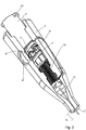
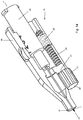
- Fig. 1 shows a first embodiment of an attachment 1 according to the invention with a proximal part 2, which carries a cannula 3, and with a distal part 4.
- the cannula 3 is axially guided through the entire proximal part and protrudes on its distal side.
- the distal part 4 surrounds the proximal part 2 and in particular also the cannula 3 at least in sections, that is to say over at least a partial circumference and / or a partial length measured in the axial direction.
- the proximal part 2 comprises a spiral groove 5 into which two guide tips or pins 6 and 7 of the distal part 4 engage.
- the spiral groove 5 extends over a total length d 2 of a base body of the proximal part 2 with the axial extension d 1 and enables the cannula 3 to be moved out by a length d 3 when the guide tips 6 and 7 slide in the spiral groove 5, see Fig. 2 ,
- the scale is designed in such a way that an indication of the respective penetration depth can be read through the magnifying lens 8 as information.
- the ratio of d 2 to d 1 is 40%.
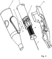
- a lamella 15 is arranged on the distal part 4, the tip 16 of which engages in the spaces 14 between the teeth 13. If the distal part 4 is rotated relative to the proximal part 2, the metal lamella 15 is bent elastically until its tip 16 leaves an intermediate space 14 and engages in the next, adjacent intermediate space 14.
- the in the Fig. 1 and 2 partially visible end face 17 can be flat or concave or convex, whereby even with a curvature a relatively small angle of less than 15 ° is provided at the edge relative to the area around the exit point of the cannula 3.
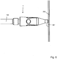
- the syringe 100 with the attachment 1 can be placed in a stable manner at an angle of 90 ° or deviate slightly from an angle a that is at most 45 ° from 90 °.
- the Fig. 8 shows a section of the proximal part with a locking button 18, which belongs to the distal part, the rest of which in Fig. 8 is not shown.
- a locking projection 19 can be released, which can engage in a recess 20 of a plate 21.
- the in Fig. 9 shown release position can be achieved and the distal part 4 are rotated relative to the proximal part 2 to extend the cannula.
- Fig. 12 shows a second, not claimed embodiment of an attachment 1a, in which the proximal part 2a has recesses 24 in the area of its groove 5a, which are triangular, so that there is a sequence of teeth 23 into which the guide tip 6 can snap.
- the latching option is thus predetermined by the groove 5a itself.
- the cylindrical body 10 with the ring gear is no longer required, and instead a spring element 25 is provided which is supported on an annular seat 26 of the distal part 4a.
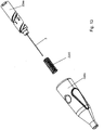
- Fig. 13 shows this embodiment in an exploded view.
- the attachment 1 can be connected to a syringe or can instead be integrated into an ultrasound head for observing the location where the syringe is to be inserted.
- Fig. 16 is a dosing regulator attachment for a syringe combined with attachment 1 or 1b according to one of the embodiments of the inventions.
- the distal part 4 or 4a, 4b can be made of very soft plastic, which enables the distal part to be compressed and the proximal part 2, 2a, 2b to be held immediately.
- the cylindrical jacket 34 is preferably transparent in the region of the end face 17, so that the end of the cannula 3 can also be seen during the spraying process.
- the cannula 3 is suitably bevelled, compare for example as in Fig. 14 seen to facilitate precise placement of the cannula in or under the skin or facial skin of a human patient and then further into a facial muscle, subcutis or other organ or tissue.
Landscapes
- Health & Medical Sciences (AREA)
- Life Sciences & Earth Sciences (AREA)
- Veterinary Medicine (AREA)
- Public Health (AREA)
- General Health & Medical Sciences (AREA)
- Animal Behavior & Ethology (AREA)
- Engineering & Computer Science (AREA)
- Heart & Thoracic Surgery (AREA)
- Hematology (AREA)
- Biomedical Technology (AREA)
- Anesthesiology (AREA)
- Vascular Medicine (AREA)
- Pharmacology & Pharmacy (AREA)
- Chemical & Material Sciences (AREA)
- Medicinal Chemistry (AREA)
- Epidemiology (AREA)
- Bioinformatics & Cheminformatics (AREA)
- Immunology (AREA)
- Gastroenterology & Hepatology (AREA)
- Proteomics, Peptides & Aminoacids (AREA)
- Dermatology (AREA)
- Infusion, Injection, And Reservoir Apparatuses (AREA)
Description
- Die Erfindung betrifft einen Aufsatz für eine oder an einer Vorrichtung zum Injizieren einer Flüssigkeit in oder unter die Haut, zum Beispiel von Botulinumtoxin in einen menschlichen Patienten.
- Die Verabreichung von Botox (Botulinumtoxin) kann schwierig sein, da der behandelnde Arzt die Einstichtiefe der Spritze bei einem Einstichwinkel von zwischen 45° und 90° mit großem Geschick von Hand einstellen muss. Auf dem Gebiet dermaler Zugangsvorrichtungen, bei denen ein Einstich subkutan mit einem Einstichwinkel von weniger als 25° erfolgt, ist es aus der
DE 10 2010 001 506 A1 bekannt, eine Kanüle für die Injektion der zu verabreichenden Flüssigkeit in zwei Stellungen zu verrasten, wobei bei der ersten Stellung die Kanüle weiter ausgefahren ist und die zweite Stellung durch Zurückfahren der Kanüle erreicht wird. Aus derWO 2009/107945 A2 , derUS 8,858,498 B2 , derWO 2013/121307 A1 , derDE 72 42 473 U undWO 2012/029082 A1 ist es bekannt, mehrteilige Aufsätze für Spritzen bereit zu stellen, wobei ein distales Teil gegenüber einem proximalen Teil beweglich ist, wobei durch die Bewegung ein Ausmaß des Herausragens einer Kanüle aus dem distalen Teil veränderbar ist. - Im Falle der Vorrichtung gemäß der
WO 2009/107945 A2 ist ein distales Teil mit einem Innengewinde versehen und ein proximales Teil des Aufsatzes mit einem Außengewinde an seinem distalen Ende versehen. Das distale Teil wird auf das Außengewinde des proximalen Teiles aufgeschraubt. Vor dem Außengewinde an dem proximalen Teil ist eine Skala vorgesehen, die je nach Ausmaß ihrer Bedeckung unterschiedliche maximale Zahlenwerte sichtbar lässt. Nachteilig an dieser Anordnung ist der geringe Halt des distalen Teils, wenn die Kanüle nur wenig herausstehen soll und eine maximale Zahl der Skala ablesbar ist. Weiterhin nachteilig ist, dass keine diskreten Positionen einstellbar sind, und die Einstellung nur optisch zu kontrollieren ist und nicht taktil und akustisch. Weiterhin nachteilig ist, dass die Zahlenwerte auf der Skala nicht die Injektionstiefe angeben, sondern die Verkürzung der eingeschobenen Kanüle. Weiterhin nachteilig sind potenzielle Fehlermöglichkeiten, die sich durch die Möglichkeit ergeben, verschiedenen Kanülen für die Benutzung mit dem Gerät auszuwählen. - Bei dem Aufsatz der
US 8,858,498 B2 sind zwei oder mehr stabile Positionen vorgesehen, die das distale Teil gegenüber dem proximalen Teil stabil einnehmen kann. DieWO 2013/121307 A1 zeigt mehrere stabile Raststellungen des distalen Teils. Im Falle der Stichtiefeneinstellung aus derDE 72 42 473 U ist es bekannt, auf einer Achse aufeinanderfolgend Sägezahnstrukturen vorzusehen, durch die der Aufsatz gegenüber einer Spritze stabil verrastbar ist. DieWO 2012/029082 A1 zeigt ebenfalls einen zweiteiligen Aufsatz für eine Spritze, wobei eine Nadel der Spritze beide Aufsatzteile durchdringt, wenn sich die Spritze an dem proximalen, inneren Aufsatzteil abstützt. Durch Drehung des proximalen Aufsatzteiles gegenüber dem distalen Aufsatzteil kann die Stichtiefe eingestellt werden. Auch hieran ist nachteilig eine geringe Stabilität der Anordnung. - Es ist ferner das Konzept bekannt, die Spritze im Ganzen gegenüber einem Aufsatz zu verschieben. Im Falle einer Einstichtiefeneinstellung aus der
EP 2 523 707 B1 fährt beispielsweise eine Spritze für Insulin auf einem Schlitten gegenüber einem Gehäuse. Das Verfahren erfolgt über ein Getriebe, das einen großen Zahnkranz außerhalb des Schlittens und eine kleinen Zahnkranz auf einem drehbaren Zylinder als Teil des Schlittens umfasst. In derUS 2001/0047151 A1 ist an einem Spritzenaufsatz eine Schraubenmutter vorgesehen, die zugleich als Sitz für eine Schürze an dem nadelseitigen Ende der Spritze vorgesehen ist. DieDE 200 135 79 U1 offenbart ferner ein nachfüllbares Dosier- und Injektionsgerät, bei dem mittels einer Stellmutter eine Einstichtiefe einer Kanüle festlegbar ist. Zur Regelung der Einstichtiefe einer Nadel ist es aus derWO 98/50094 A1 -
EP 0 904 790 A2 offenbart eine Stiftnadel, die einen Extender aufweist, der drehbar an einem Hub auf der Stiftnadel angebracht ist, um die Stiftnadel auf eine gewünschte Injektionslänge einzustellen. Der Extender kann in verschiedene vordefinierte Stellungen gebracht werden, wobei jede Stellung einer vordefinierten Injektionslänge entspricht. -
EP 2 388 033 A1 offenbart einen an eine Spritze ankoppelbaren Rohraufsatz, der einen Entkopplungskörper und ein Steuerrohr umfasst. Das Steuerrohr wird an das obere Ende der Spritze angekoppelt und ist auf dem Kopplungskörper gleitend bewegbar. Das Steuerrohr weist auch ein Loch auf, durch das die Kanüle der Spitze treten kann. - Der Erfindung liegt die Aufgabe zugrunde, eine zuverlässige technische Hilfe beim Zuführen von Botox in und unter die Haut eines menschlichen Patienten bereitzustellen.
- Die der Erfindung zugrundeliegende Aufgabe wird durch einen Aufsatz für eine oder an einer Vorrichtung zum Injizieren einer Flüssigkeit in oder unter die Haut, zum Beispiel von Botulinumtoxin in einen menschlichen Patienten, nach Anspruch 1 gelöst, wobei der Aufsatz ein proximales Teil aufweist, das an die Vorrichtung ankoppelbar oder mit dieser verbunden ist, und das eine Kanüle trägt, wobei der Aufsatz ferner ein distales Teil aufweist, das die Kanüle zumindest abschnittsweise umgibt und wobei das proximale Teil und das distale Teil derart zueinander drehbeweglich sind, dass ein Ausmaß des Herausragens der Kanüle aus dem distalen Teil veränderbar ist. Die Drehbeweglichkeit beinhaltet, dass bei der Drehbewegung von proximalem zu distalem Teil oder umgekehrt eine diskrete Anzahl von Haltestellungen erreicht werden kann. Eine Haltestellung ist eine Stellung, in der die Bewegung aus der Haltestellung heraus in zumindest eine Richtung durch einen Widerstand beschränkt ist. Der Widerstand ist Vorzugsweise durch Aufwenden von Kraft überwindbar.
- Die Bewegung ist sowohl in eine Richtung beschränkt, die ein Hereinfahren der Kanüle in das distale Teil bewirkt, als auch in eine Richtung, die ein Herausfahren der Kanüle in das distale Teil bewirkt. Der Widerstand ist durch einen Rastmechanismus verwirklicht. Es gibt mindestens zwei, besonders mindestens drei, weiter vorzugsweise mindestens fünf, und im höchsten Maß vorzugsweise mindestens zehn solcher Haltestellungen, wobei beispielsweise pro Millimeter Ausfahrlänge der Kanüle aus dem distalen Teil zwischen einer und zwanzig, beispielsweise mindestens drei, vier, fünf oder zehn Haltestellungen durchlaufen werden. Es ist ein Rastmechanismus vorgesehen, der eine Mehrzahl von Raststellungen bereitstellt, denen ein unterschiedliches Ausmaß des Herausragens der Kanüle aus dem distalen Teil entspricht. Eine Raststellung im Sinne der vorliegenden Anmeldung kann durch Formschluss bereitgestellt sein, alternativ aber auch mittels Kraftschluss erzielt werden, z.B. ist durch eine lokale Änderung des Materials oder der Oberflächenrauigkeit erzielbar, dass ein Reibwiderstand variiert. Die Rasteinrichtung weist eine oder mehrere Nut(en) und mindestens eine in die Nut(en) eingreifendes elastisches Rastglied auf.
- Mit der Erfindung ist es dem behandelnden Arzt möglich, die Kanüle über eine definierte Länge aus dem distalen Teil herausragen zu lassen. Diese Länge entspricht der späteren Einstichtiefe, wenn eingestochen wird, bis das distale Teil, beispielsweise mit einer geeignet ausgebildeten Stirnfläche, die Haut berührt. Durch das Vorsehen der Haltestellungen ist dem behandelnden Arzt eine haptische oder taktile und gegebenenfalls auch akustische Erfassung der Ausfahrlänge der Kanüle ermöglicht. Ferner kann bei bereits in den menschlichen Patienten eingestochener Kanüle noch eine Nachregelung möglich sein, indem die nächste oder eine weitere Raststellung durch Drehen nunmehr des proximalen Teils gegenüber dem distalen Teil eingenommen wird. Ebenso kann auch ein Herausfahren durch Drehung in Gegenrichtung möglich sein.
- Vorteilhafte Aus- oder Weiterbildungen, welche einzeln oder in Kombination miteinander eingesetzt werden können, sind Gegenstand der abhängigen Ansprüche betreffend den ersten Aspekt der Erfindung.
- Vorzugsweise ist bei dem Aufsatz vorgesehen, dass die Raststellungen beim Drehen des distalen Teiles in dieselbe Drehrichtung sukzessive durchlaufen werden und sich hierbei das Ausmaß des Herausragens der Kanüle entweder ständig weiter vergrößert oder ständig weiter verkleinert. Eine solche Lösung ist mechanisch sehr einfach umsetzbar.
- Der Aufsatz umfasst einen Zahnkranz aus axial verlaufenden Zähnen mit dazwischen liegenden axial verlaufenden Nuten und weist ferner ein elastisches Rastglied auf, das in einer Raststellung in eine der Nuten eingreift. Somit kann der Zahnkranz gedreht werden, wenn das proximale oder wenn das distale Teil gedreht wird. Die Raststellungen werden dann beim Drehen auf natürliche Weise durchlaufen. Wird das elastische Rastglied - wie vorzugsweise vorgesehen - als metallene Lamelle ausgebildet, ist es einerseits sehr einfach bereitzustellen, sorgt aber andererseits für eine stabile Verrastung.
- Wenn der Zahnkranz an dem proximalen Teil ausgebildet ist und er näher an der Kanüle angeordnet ist als ein Gewinde, das die Drehbewegung des distalen Teils gegenüber dem proximalen Teil ermöglicht, dann ist erreichbar, dass das distale Teil stabiler an dem proximalen Teil gehalten ist als wenn das Gewinde weiter vorne, das heißt, weiter distal, ausgebildet ist. Zudem ist die Verrastung stabiler, wenn sie im Nahbereich der Kanüle und damit des Patienten erfolgt.
- Wenn der Zahnkranz an einer Innenseite des distalen Teiles ausgebildet ist, ist erreichbar, dass eine größere Anzahl von Rastpositionen bei vorgegebenem Außenumfang des Aufsatzes eingenommen werden können als wenn der Zahnkranz an der Außenseite des proximalen Teils ausgebildet ist.
- Der bevorzugte erfindungsgemäße Aufsatz umfasst außen an dem proximalen Teil eine Spiralnut, in die das distale Teil eingreift. Auf diese Weise ist erreichbar, dass das distale Teil das proximale Teil als Ganzes umgeben und zur Montage einfach aufgesetzt werden kann. Weiter bevorzugt ist es, dass bei an dem proximalen Teil ausgebildetem Zahnkranz, der näher an der Kanüle ist als es die Spiralnut ist, das distale Teil und das proximale Teil jeweils von kreisrundem Querschnitt sind, und der Zahnkranz eine maximale radiale Erstreckung hat, welche kleiner ist als der radiale Abstand eines Grundes der Spiralnut. Mit anderen Worten ist das proximale Teil an seinem distalen Ende weniger dick als an der Vorrichtung zum Injizieren von Flüssigkeit zugewandten Ende. So wird durch eine feine, dünne Spitze ein Präzisionswerkzeug geschaffen, mit dem sehr fein punktiert werden kann, und das die Punktionsstelle während der Punktion nicht breit abdeckt, so dass die Injektionsflüssigkeit sehr gezielt und präzise verabreicht werden kann.
- Die Spiralnut kann in vorteilhafter Weise derart ausgebildet sein, dass zwischen ihren verschiedenen Abschnitten ein eine Information tragender Abschnitt (also erhaben zwischen den Spiralnuten) angeordnet ist, insbesondere ein Abschnitt mit einer Zahl, einem Buchstaben, einem Symbol, einem Skalenstrich, einem Grauwert aus einer Grauskala oder einer Farbe aus einer Farbskala oder einer Kombination aus einem oder mehreren dieser vorgenannten Elemente. Somit wird die Spiralnut über eine größere axiale Länge gestreckt, wo mit weniger Drehungen ein größerer axialer Bereich durch das distale Teil durchlaufen werden kann, die Kanüle also mit relativ wenigen Drehungen freigelegt und verlängert werden kann bzw. umgekehrt verkürzt werden kann, was das Ausmaß ihres Herausragens angeht. Diese Ausführungsform kann durch geeignetes Vorsehen des Rastmechanismus mit einer Mehrzahl oder gar Vielzahl von Raststellungen optimal ausgebildet werden. Als Information ist vorzugsweise die jeweilige Einstichtiefe beziehungsweise das Ausmaß des Herausragens der Kanüle aus dem distalen Teil ablesbar.
- Der bevorzugte erfindungsgemäße Aufsatz umfasst alternativ zu der Spiralnut an dem proximalen Teil außen in einem inneren Hohlraum des proximalen Teils ein Innengewinde, in welches ein Schaft des distalen Teils eingreift. In diesem Fall lässt sich die Außenfläche des proximalen Teils freier gestalten.
- Als Alternative zu dem Zahnkranz aus axial verlaufenden Zähnen kann eine Mehrzahl von Zähnen mit Zwischenräumen (Nuten) bereitgestellt sein, wobei ein elastisches Rastglied in einen Zwischenraum (Nut) eingreift, wenn es eine Raststellung einnimmt, wobei es in axialer Richtung elastisch bewegbar ist. Die elastische Beaufschlagung in axialer Richtung sorgt in erhöhtem Maße für eine Stabilität beim Injizieren.
- Bei einer dritten Alternative ist unter Verzicht auf einen gesonderten Zahnkranz im Bereich einer außen an dem proximalen Teil vorgesehene Spiralnut, in die das distale Teil eingreift, eine Mehrzahl von Rastvertiefungen vorgesehen, wobei diese konkav und rund sein können oder als eckige Aussparungen bzw. Vertiefungen ausgebildet sein können. Diese Ausführungsform hat den Vorteil einer hohen Kompaktheit.
- Gemäß einem zweiten Aspekt der Erfindung ist ein Aufsatz für eine oder an einer Vorrichtung zum Injizieren einer Flüssigkeit in oder unter die Haut, zum Beispiel von Botulinumtoxin in einen menschlichen Patienten bereitgestellt, wobei der Aufsatz ein proximales Teil aufweist, welches an die Vorrichtung ankoppelbar oder mit dieser verbunden ist, und das eine Kanüle trägt, wobei das proximale Teil in einem Abschnitt eine Spiralnut auf seiner Außenseite aufweist. In die Spiralnut greift ein distales Teil ein, welches die Kanüle zumindest abschnittsweise umgibt, wobei das proximale Teil und das distale Teil derart zueinander drehbeweglich sind, dass das Ausmaß des Herausragens der Kanüle aus dem distalen Teil veränderbar ist. Es sind axial aufeinanderfolgend Abschnitte der Spiralnut durch solche erhabenen Abschnitte des proximalen Teils voneinander beabstandet, welche eine Information tragen, die mit Hilfe von Zahlen, Buchstaben, Symbolen, Skalenstrichen und/oder einer Grau- oder Farbskala angegeben ist oder einer Kombination aus einem oder mehreren dieser vorgenannten Elemente. Als Information ist vorzugsweise die jeweilige Einstichtiefe beziehungsweise das Ausmaß des Herausragens der Kanüle aus dem distalen Teil ablesbar. Mit anderen Worten ist hier vorgesehen, dass die Spiralnut bei nur geringer Drehung eine relativ große axiale Strecke durchläuft. Um den Platz optimal zu nutzen, ist eben die Skala, welche insbesondere die Information wiedergibt, wie weit die Kanüle heraussteht, zwischen den Abschnitten der Spiralnut vorgesehen.
- Vorzugsweise ist insbesondere vorgesehen, dass sich die Spiralnut über einen axialen Abschnitt von zwischen 20 % und 60 % der axialen Gesamterstreckung eines die Kanüle tragenden Körpers des proximalen Teils erstreckt. Mit anderen Worten wird ein sehr großer Anteil des proximalen Teils dazu verwendet, die Spiralnut bereitzustellen, wodurch die Einstichtiefe (das Ausmaß des Herausragens der Kanüle) im Verhältnis zur Gesamtgröße des Aufsatzes sehr stark variiert werden kann.
- Gemäß einem dritten Aspekt der Erfindung ist ein Aufsatz für eine oder an einer Vorrichtung zum Injizieren einer Flüssigkeit in oder unter die Haut, insbesondere von Botulinumtoxin in einen menschlichen Patienten, bereitgestellt, wobei der Aufsatz ein proximales Teil aufweist, das an die Vorrichtung ankoppelbar oder mit dieser verbunden ist, das eine Kanüle aufweist und in einem Abschnitt eine Spiralnut auf seiner Außenseite aufweist. In die Spiralnut greift ein distales Teil ein, das die Kanüle zumindest abschnittsweise umgibt. Das distale Teil und das proximale Teil sind derart zueinander drehbeweglich, dass das Ausmaß des Herausragens der Kanüle aus dem distalen Teil veränderbar ist. Die Spiralnut erstreckt sich über einen axialen Abschnitt von zwischen 20 % und 60 % der axialen Gesamterstreckung eines die Kanüle tragenden Körpers des proximalen Teils. Hier wird somit ein sehr großer Anteil des proximalen Teils für die Spiralnut genutzt, so dass im Verhältnis zur Gesamtgröße des Aufsatzes das Ausmaß des Herausragens der Kanüle sehr stark variiert werden kann.
- Bei dem Aufsatz gemäß allen drei Aspekten ist vorzugsweise eine Einrichtung an dem distalen Teil vorgesehen, mit Hilfe derer das distale Teil an dem proximalen Teil in einer Stellung festhaltbar ist, wobei es sich hierbei vorzugsweise um eine solche Stellung handelt, in der die Kanüle nicht aus dem distalen Teil herausragt. So wird für einen Nadelstichschutz vor der Injektion beim Aufsetzen der Vorrichtung zum Injizieren oder auch nach dem Einfahren der Kanüle und bei einem Wechsel der Vorrichtung zum Injizieren gesorgt. Durch diese Einrichtung - etwa in Form einer Arretierungstaste - ist vorzugsweise ein noch stabilerer Halt in der Stellung erzielbar als mit Hilfe des Rastmechanismus.
- Gemäß einem vierten Aspekt ist ein Aufsatz für eine oder an einer Vorrichtung zum Injizieren einer Flüssigkeit in oder unter die Haut, zum Beispiel von Botulinumtoxin in einen menschlichen Patienten bereitgestellt, wobei der Aufsatz ein proximales Teil aufweist, das an die Vorrichtung ankoppelbar oder mit dieser verbunden ist, und das eine Kanüle trägt. Ein distales Teil umgibt die Kanüle zumindest abschnittsweise und ist gegenüber dem proximalen Teil translatorisch beweglich, so dass ein Ausmaß des Herausragens der Kanüle aus dem proximalen Teil veränderbar ist. Eine Stellschraube greift in ein Gewinde an dem proximalen oder dem distalen Teil ein und weist außerhalb des anderen Teils einen Griff, beispielsweise mit einer Riffelung, zum Angreifen auf. Beim Vorsehen einer solchen Stellschraube zum Verfahren des distalen Teils gegenüber dem proximalen Teil ist durch die Schraube selbst für einen stabilen Halt gesorgt.
- Bei allen vier genannten Aspekten des erfindungsgemäßen Aufsatzes umfasst vorzugsweise das distale Teil zumindest einen Abschnitt aus einem elastischen nachgebenden Material, so dass durch einen Benutzer das distale Teil soweit zusammendrückbar ist, dass das proximale Teil fassbar ist. Dadurch ist die Handhabung erleichtert.
- In einer Ausführungsform umfasst das distale Teil eine Stirnfläche auf, welche flach ist. Alternativ kann eine solche Stirnfläche vorhanden sein, welche gewölbt ist, zum Beispiel im Ganzen konvex oder im Ganzen konkav ist. Durch eine flache oder gewölbte Stirnfläche ist es möglich, das distale Teil stabil auf die Haut eines menschlichen Patienten aufzusetzen, wobei sie insbesondere einen geeigneten Endpunkt der Injizierbewegung darstellt. Der für eine Injektion von Botox bevorzugte Einstechwinkel von zwischen 45° und 90° kann bei geeigneter Ausbildung der Stirnfläche für den behandelnden Arzt leichter erzielbar sein. Weiter alternativ kann das distale Teil an seinem distalen (freien) Ende spitz ausgebildet sein, vorzugsweise konisch zulaufen, was eine Sichtkontrolle beim Einstechen erleichtert.
- Bei einer bevorzugten Ausführungsform in allen vier genannten Aspekten ist das distale Teil zumindest an seinem distalen Ende abschnittsweise (z.B. nur über einen Teilumfang) oder vollständig transparent. Dadurch kann beim Injizieren der Kanüle in die Haut und nachfolgend in den Gesichtsmuskel eine Sichtkontrolle durch den behandelnden Arzt erfolgen.
- Ferner ist bei allen Aspekten der Erfindung vorzugsweise in dem distalen Teil ein transparentes Fenster, gegebenenfalls mit einem Vergrößerungsglas, eine Öffnung oder auch eine elektrisch betriebene Anzeigevorrichtung vorgesehen. Durch das Fenster, das Vergrößerungsglas oder die Öffnung ist eine darunter liegende Skala, insbesondere auf dem proximalen Teil, ablesbar. Die elektrisch betriebene Anzeige kann ebenfalls eine Information über die Einstichtiefe (bzw. das Ausmaß des Herausragens der Kanüle aus dem distalen Teil) geben.
- Der Aufsatz kann auf verschiedene Weise bereitgestellt sein.
- Der Aufsatz kann auf seinem proximalen Teil eine Kupplung zum Ankoppeln an die Vorrichtung zum Injizieren an der Flüssigkeit aufweisen, z.B. in Form eines Luer Lock®, eines Luer Slip®, eines Konus zum Ankoppeln einer Spritze oder eines Schlauchanschlusses. Dadurch kann der Aufsatz gesondert bereitgestellt werden und flexibel an unterschiedliche Arten von Vorrichtungen zum Injizieren einer Flüssigkeit angekoppelt werden.
- Alternativ kann der Aufsatz integral mit der Vorrichtung zum Integrieren einer Flüssigkeit sein, so dass der behandelnde Arzt ihn nicht selbst anbringen muss und die Vorrichtung zum Injizieren einer Flüssigkeit mit dem Aufsatz kompakt lagerbar ist.
- Weiter alternativ kann der Aufsatz in einem Ultraschallkopf für ein Ultraschallgerät / eines Ultraschallgerätes integriert sein.
- Schließlich kann auch der Aufsatz in oder an einem Dosier-Regler-Aufsatz für eine Vorrichtung zum Injizieren einer Flüssigkeit ausgebildet sein, d.h. man kann gleich zwei Aufsatzeinheiten gemeinsam vorsehen.
- Die Erfindung wird im Folgenden anhand schematischer Zeichnungen in weiteren Einzelheiten näher erläutert. Es zeigen:
- Fig. 1:
- einen Aufsatz gemäß einem ersten Ausführungsbeispiel in perspektivischer, teilweise offener Ansicht, wobei die Kanüle nicht aus dem Aufsatz hervorsteht;
- Fig. 2:
- den Aufsatz aus
Fig. 1 in einer Stellung, in der die Kanüle um einen Abstand d3 herausragt; - Fig. 3:
- eine Explosionsansicht des Aufsatzes aus
Fig. 1 ; - Fig. 4:
- den Aufsatz aus
Fig. 1 , abgeschnitten an der Linie IV-IV in perspektivischer Ansicht; - Fig. 5:
- den Schnitt IV-IV aus
Fig. 1 ; - Fig. 6:
- den Aufsatz aus
Fig. 1 mit daran angesetzter Spritze, wobei der Aufsatz in einem Winkel von 90° auf einer eine Patientenhaut schematisch darstellenden Ebene steht; - Fig. 7:
- den Aufsatz aus
Fig. 6 , nur um einen Winkel von kleiner als 45° gedreht; - Fig. 8:
- einen perspektivischen Teilausschnitt des proximalen Teils mit einer zum distalen Teil gehörigen Arretierungstaste gemäß einer ersten Ausführungsform in einer Verriegelungsstellung und
- Fig. 9:
- die Darstellung aus
Fig. 8 in entriegelter Stellung; - Fig. 10:
- einen perspektivischen Teilausschnitt des proximalen Teils mit einer zum distalen Teil gehörigen Arretierungstaste gemäß einer zweiten Ausführungsform in einer Verriegelungsstellung und
- Fig. 11
- die Darstellung aus
Fig. 10 in entriegelter Stellung; - Fig. 12:
- einen Aufsatz gemäß eines zweiten Ausführungsbeispiels in perspektivischer, teilweise offener Ansicht, wobei die Kanüle nicht aus dem Aufsatz hervorsteht;
- Fig. 13:
- eine Explosionsdarstellung des Aufsatzes aus
Fig. 12 ; - Fig. 14:
- einen Aufsatz gemäß eines dritten Ausführungsbeispiels in perspektivischer, teilweise offener Ansicht, wobei die Kanüle nicht aus dem Aufsatz hervorsteht;
- Fig. 15:
- den Aufsatz aus
Fig. 14 im Längsschnitt XV-XV; - Fig. 16:
- einen Dosier-Regler-Aufsatz bei dem die Erfindung in einem Aspekt ebenfalls verwirklicht ist.
- Das Verabreichen von Botulinumtoxin (Botox) mithilfe einer Spritze (Verfahrkolben in Flüssigkeitsreservoir) soll erleichtert werden, und zwar soll insbesondere zunächst die präzise Tiefeneinstellung der Injektion erleichtert und ein zu flaches oder zu tiefes Einstechen verhindert werden. Ferner sollen mehrere, schnelle, repetitive Injektionen hintereinander in die gleiche Tiefe erleichtert werden.
-
Fig. 1 zeigt ein erstes Ausführungsbeispiel eines erfindungsgemäßen Aufsatzes 1 mit einem proximalen Teil 2, welches eine Kanüle 3 trägt, und mit einem distalen Teil 4. Die Kanüle 3 ist durch das gesamte proximale Teil axial geführt und steht an dessen distaler Seite heraus. Das distale Teil 4 umgibt das proximale Teil 2 und insbesondere auch die Kanüle 3 zumindest abschnittsweise, also über zumindest einen Teilumfang und/oder eine in axialer Richtung gemessene Teillänge. Das proximale Teil 2 umfasst eine Spiralnut 5, in die zwei Führungsspitzen oder -zapfen 6 und 7 des distalen Teils 4 eingreifen. Zwischen den Führungsspitzen 6 und 7 befindet sich eine Vergrößerungslinse 8, durch die hindurch ein zwischen zwei Abschnitten der Spiralnut 5 befindlicher erhabener Teil 9, der eine Skala, vorliegend in Form von Zahlwerten, trägt, sichtbar ist. Die Spiralnut 5 erstreckt sich über eine Gesamtlänge d2 eines Grundkörpers des proximalen Teils 2 mit der axialen Erstreckung d1 und ermöglicht bei einem Gleiten der Führungsspitzen 6 und 7 in der Spiralnut 5 ein Herausfahren der Kanüle 3 um eine Länge d3, sieheFig. 2 . Die Skala ist derart gestaltet, dass durch die Vergrößerungslinse 8 als Information eine Angabe der jeweiligen Einstichtiefe ablesbar ist. - Das Verhältnis von d2 zu d1 beträgt 40 %.
- An den die Spiralnut 5 tragenden Grundkörper, zu dem die axiale Erstreckung d1 definiert ist, schließt sich ein vom Grundkörper verschiedener zylindrischer Abschnitt 10 an, der einen Zahnkranz mit Zähnen 13 trägt, zwischen denen sich Zwischenräume in Form axialer Nuten 14 befinden, s.
Fig. 3 bis 5 . Am distalen Teil 4 ist eine Lamelle 15 angeordnet, deren Spitze 16 in die Zwischenräume 14 zwischen den Zähnen 13 eingreift. Wird das distale Teil 4 gegenüber dem proximalen Teil 2 gedreht, dann wird die Metalllamelle 15 elastisch gebogen, bis ihre Spitze 16 einen Zwischenraum 14 verlässt und in den nächsten, benachbarten Zwischenraum 14 einrastet. Auf diese Weise kann das distale Teil 4 stabil gegenüber dem proximalen Teil 2 gehalten werden und dennoch eine Einstichtiefe der Kanüle 3, also das Ausmaß d3 ihres Herausstehens, sukzessive vergrößert oder verkleinert werden. Insbesondere kann die Situation an den zu spritzenden Patienten angepasst werden. - Die
Fig. 6 zeigt den Aufsatz 10 mit daran angekoppeltem Spritzenkörper 100 als einer Vorrichtung zum Injizieren von Flüssigkeit in oder unter die Haut, insbesondere von Botulinumtoxin in Gesichtsmuskeln eines menschlichen Patienten. Die Haut ist inFig. 6 schematisch durch eine Ebene 200 angedeutet. Die Spritze wird mit Hilfe eines an dem proximalen Teil 2 vorgesehenen Luer Lock ® 33 (sieheFig. 1 ,Fig. 2 ) an dem Aufsatz 1 befestigt. - Die in den
Fig. 1 und2 teilweise sichtbare Stirnfläche 17 kann flach oder konkav oder konvex gewölbt sein, wobei auch bei einer Wölbung ein relativ kleiner Winkel von unter 15° am Rand gegenüber den Bereich um den Austrittspunkt der Kanüle 3 herum vorgesehen ist. Wie aus denFig. 6 und7 zu sehen, kann dadurch die Spritze 100 mit dem Aufsatz 1 stabil in einem Winkel von 90° aufgesetzt werden oder geringfügig um einen Winkel a, der höchstens 45° beträgt, von 90° abweichen. - Insbesondere dann, wenn die Situation gemäß
Fig. 1 gegeben ist, also die Kanüle 3 nicht aus dem distalen Teil 4 herausragt, ist es erwünscht, dass das distale Teil 4 stabil gegenüber dem proximalen Teil 2 verrastet, was einen Nadelstichschutz während des Aufsteckens der Spritze sowie nach dem Zurückfahren der Kanüle bietet. DieFig. 8 zeigt hierzu einen Ausschnitt des proximalen Teils mit einer Arretierungstaste 18, welche zum distalen Teil gehört, das im Übrigen inFig. 8 nicht gezeigt ist. Durch Betätigen der Arretierungstaste 18 kann ein Rastvorsprung 19 freigegeben werden, der in einer Aussparung 20 eines Tellers 21 eingreifen kann. Durch Betätigen der Arretierungstaste 18, bei der sich selbige um eine Welle 22 dreht, kann die inFig. 9 gezeigte Freigabestellung erzielt werden und das distale Teil 4 gegenüber dem proximalen Teil 2 gedreht werden, um die Kanüle herauszufahren. - Während im Falle der
Fig. 8 und 9 durch den Rastvorsprung 19 eine Drehbewegung des distalen Teils gegenüber dem proximalen Teil unterbunden ist, ist im Falle der Ausführungsformen gemäßFig. 10 und 11 eine axiale Bewegung des distalen Teils gegenüber dem proximalen Teil unterbunden, was einen Nadelstichschutz während des Aufsteckens der Spritze sowie nach dem Zurückfahren der Kanüle bietet. -
Fig. 12 zeigt ein zweites, nicht beanspruchtes Ausführungsbeispiel eines Aufsatzes 1a, bei dem das proximale Teil 2a im Bereich seiner Nut 5a Aussparungen 24 aufweist, die dreieckig sind, so dass sich eine Folge von Zähnen 23 ergibt, in die die Führungsspitze 6 einrasten kann. Hier ist somit durch die Nut 5a selbst die Rastmöglichkeit vorgegeben. Der zylindrische Körper 10 mit dem Zahnkranz ist nicht mehr erforderlich, und stattdessen ist ein Federelement 25 vorgesehen, welches sich an einem ringförmigen Sitz 26 des distalen Teils 4a abstützt.Fig. 13 zeigt diese Ausführungsform in Explosionsansicht. -
Fig. 14 zeigt ein drittes nicht beanspruchtes Ausführungsbeispiel eines Aufsatzes 1b, bei dem an das proximale Teil 2b ein Ansatz 28 angeformt ist und an das distale Teil 4b ein Ansatz 27 angeformt ist. Eine Stellschraube 29 ist durch beide Ansätze 27 und 28 geführt und greift insbesondere in ein inFig. 14 durch Strichlierung angedeutetes Innengewinde des Ansatzes 28 ein. Gegebenenfalls kann auch im Ansatz 27 ein Innengewinde vorgesehen sein. Ein Kopf 30 der Stellschraube 29 ist mit einer Riffelung 31 zur leichteren Handhabung versehen: Eine Bedienperson kann an dem Kopf 30 drehen und dadurch bewirken, dass die Stellschraube das proximale Teil 2b axial gegenüber dem distalen Teil 4b verschiebt. Diese translatorische Bewegung hat etwa zur Folge, dass die Kanüle 3 aus der Stirnfläche 17 des distalen Teils 4b austritt. - Der Aufsatz 1 kann außer über dem Luer Lock ® 33 mit einer Spritze verbunden sein oder auch stattdessen in einen Ultraschallkopf zur Beobachtung der Stelle, wo die Spritze eingebracht werden soll, integriert sein. Im Falle der
Fig. 16 ist ein Dosier-Regler-Aufsatz für eine Spritze mit dem Aufsatz 1 oder 1b gemäß einer der Ausführungsformen der Erfindungen kombiniert. - Bei allen Ausführungsformen kann das distale Teil 4 oder 4a, 4b aus sehr weichem Kunststoff bestehen, wodurch ein Zusammendrücken des distalen Teils und ein unmittelbarer Halt des proximalen Teils 2, 2a, 2b ermöglicht ist. Vorzugsweise ist im Bereich der Stirnfläche 17 der zylindrische Mantel 34 transparent, so dass man das Ende der Kanüle 3 auch beim Vorgang des Spritzens erkennen kann. Die Kanüle 3 ist geeignet abgeschrägt, vergleiche zum Beispiel wie in
Fig. 14 zu sehen, um ein präzises Setzen der Kanüle in oder unter die Haut oder Gesichtshaut eines menschlichen Patienten und weiter dann in einen Gesichtsmuskel, in die Subkutis oder ein anderes Organ oder Gewebe zu erleichtern. - Die in der vorstehenden Beschreibung, den Ansprüchen und den Zeichnungen offenbarten Merkmale können sowohl einzeln als auch in beliebiger Kombination für die Verwirklichung der Erfindung in ihren verschiedenen Ausgestaltungen von Bedeutung sein.
Claims (21)
- Aufsatz (1, 1a) für eine oder an einer Vorrichtung (100) zum Injizieren einer Flüssigkeit in oder unter die Haut (200), wobei der Aufsatz (1, 1a) aufweist: ein proximales Teil (2, 2a), das an die Vorrichtung (100) ankoppelbar oder mit dieser verbunden ist, und das eine Kanüle (3) trägt, ein distales Teil (4, 4a) das die Kanüle (3) zumindest abschnittsweise umgibt und wobei das proximale Teil (2, 2a) und das distale Teil (4, 4a) derart zueinander drehbeweglich sind, dass ein Ausmaß (d3) des Herausragens der Kanüle (3) aus dem distalen Teil (4, 4a) veränderbar ist, wobei eine diskrete Anzahl an Haltestellungen bezüglich der Drehbewegung bereitgestellt ist, denen ein unterschiedliches Ausmaß des Herausragens der Kanüle (3) aus dem distalen Teil (4, 4a) entspricht, dadurch gekennzeichnet, dass der Aufsatz einen Rastmechanismus (10) mit einem Zahnkranz aus axial verlaufenden Zähnen (13) mit dazwischen axial verlaufenden Nuten (14) und mit einem elastischen Rastglied (15), das in einer Raststellung in einer der Nuten (14) eingreift, aufweist, die diskrete Anzahl an Haltestellungen durch eine Mehrzahl von Raststellungen bereitzustellen.
- Aufsatz (1) nach Anspruch 1, dadurch gekennzeichnet, dass die Raststellungen beim Drehen des distalen Teils (4, 4a) in dieselbe Drehrichtung sukzessive durchlaufen werden und sich hierbei das Ausmaß (d3) des Herausragens der Kanüle (3) entweder ständig weiter vergrößert oder ständig weiter verkleinert.
- Aufsatz (1) nach Anspruch 2, dadurch gekennzeichnet, dass das elastische Rastglied (15) als Lamelle ausgebildet ist.
- Aufsatz (1) nach Anspruch 3, dadurch gekennzeichnet, dass der Zahnkranz (13) an dem proximalen Teil (2) ausgebildet ist und näher an der Kanüle (3) angeordnet ist als ein Gewinde (5), das die Drehbewegung des distalen Teils (4) gegenüber dem proximalen Teil (2) ermöglicht.
- Aufsatz (1) nach Anspruch 3, dadurch gekennzeichnet, dass der Zahnkranz an einer Innenseite des distalen Teils ausgebildet ist.
- Aufsatz (1, 1a) nach einem der Ansprüche 1 bis 5, dadurch gekennzeichnet, dass außen an dem proximalen Teil (2, 2a) eine Spiralnut (5, 5a) vorgesehen ist, in die das distale Teil (4, 4a) eingreift.
- Aufsatz (1) nach Anspruch 6 in dessen Rückbezug auf Anspruch 5, dadurch gekennzeichnet, dass das distale Teil (4) und das proximale Teil (2) jeweils einen kreisrunden Querschnitt aufweisen, dass der Zahnkranz (13) eine maximale radiale Erstreckung hat, welcher kleiner ist als das radiale Abstand eines Grundes der Spiralnut (5) vom Mittelpunkt des kreisrunden Querschnitts.
- Aufsatz (1, 1a) nach Anspruch 6 oder Anspruch 7, dadurch gekennzeichnet, dass zwischen verschiedenen Abschnitten der Spiralnut (5, 5a) ein eine Information tragender Abschnitt (9) angeordnet ist, mit zumindest einem Element aus einer Zahl, einem Buchstaben, einem Symbol, einem Skalenstrich, einem Grauwert auf einer Grauskala oder einer Farbe auf einer Farbskala, oder mit einer Kombination aus einem oder mehreren dieser Elemente.
- Aufsatz nach einem der Ansprüche 1 bis 5, dadurch gekennzeichnet, dass in einem axial zur distalen Seite hin offenen Hohlraum des proximalen Teils ein Innengewinde ausgebildet ist, in das ein Schaft des distalen Teils eingreift.
- Aufsatz nach Anspruch 1, dadurch gekennzeichnet, dass eine Mehrzahl von Zähnen mit Zwischenräumen bereitgestellt ist, in die ein elastisches Rastglied eingreift, wobei das Rastglied, wenn es eine Raststellung einnimmt, in axialer Richtung elastisch bewegbar ist.
- Aufsatz (1a) nach Anspruch 1, dadurch gekennzeichnet, dass außen an dem proximalen Teil (2a) eine Spiralnut (5a) vorgesehen ist, in die das distale Teil (4a) eingreift, wobei an oder in der Spiralnut (5a) Rastvertiefungen (24) ausgebildet sind.
- Aufsatz (1) nach einem der vorhergehenden Ansprüche, gekennzeichnet durch eine Einrichtung (18, 18a) an dem distalen Teil (4), mit Hilfe der es an dem proximalen Teil (2) in einer vorbestimmten Stellung festhaltbar ist, in der die Kanüle (3) gar nicht aus dem distalen Teil (4) herausragt, um für einen Nadelstichschutz vor der Injektion beim Aufsetzen der Vorrichtung (100) zum Injizieren oder nach einem Einfahren der Kanüle oder bei einem Wechsel der Vorrichtung (100) zum Injizieren zu sorgen.
- Aufsatz (1, 1a, 1b) nach einem der vorhergehenden Ansprüche, dadurch gekennzeichnet, dass das distale Teil (4, 4a, 4b) zumindest einen Abschnitt aus einem elastisch nachgebenden Material umfasst, so dass durch einen Benutzer das distale Teil (4, 4a, 4b) soweit zusammendrückbar ist, dass das proximale Teil fassbar ist.
- Aufsatz (1, 1a, 1b) nach einem der vorhergehenden Ansprüche, dadurch gekennzeichnet, dass das distale Teil (4, 4a, 4b) eine Stirnfläche (17) aufweist, welche flach oder gewölbt ist, vorzugsweise im Ganzen konvex oder im Ganzen konkav ist.
- Aufsatz (1, 1a, 1b) nach einem der Ansprüche 1 bis 13, dadurch gekennzeichnet, dass das distale Teil (4, 4a, 4b) an seinem distalen Ende konisch zuläuft.
- Aufsatz (1, 1a, 1b) nach einem der vorhergehenden Ansprüche, dadurch gekennzeichnet, dass das distale Teil an zumindest seinem distalen Ende (34) zumindest abschnittsweise transparent ist.
- Aufsatz (1, 1a, 1b) nach einem der vorhergehenden Ansprüche, dadurch gekennzeichnet, dass ein transparentes Fenster, ein Vergrößerungsglas (7), eine Öffnung oder eine elektrisch betriebene Anzeige in bzw. an dem distalen Teil (4, 4a, 4b) bereitgestellt ist.
- Aufsatz (1, 1a, 1b) nach einem der Ansprüche 1 bis 17, dadurch gekennzeichnet, dass der Aufsatz (1, 1a, 1b) an seinem proximalen Teil (2, 2a, 2b) eine Kupplung (33) zum Ankoppeln an die Vorrichtung (100) zum Injizieren einer Flüssigkeit aufweist, insbesondere in Form eines Konus zum Ankoppeln einer Spritze oder eines Schlauchanschlusses aufweist.
- Aufsatz nach einem der Ansprüche 1 bis 17, dadurch gekennzeichnet, dass der Aufsatz mit der Vorrichtung zum Injizieren einer Flüssigkeit integral ist.
- Aufsatz nach einem der Ansprüche 1 bis 17, dadurch gekennzeichnet, dass der Aufsatz in einen Ultraschallkopf für ein Ultraschallgerät oder eines Ultraschallgerätes integriert ist.
- Aufsatz nach einem der Ansprüche 1 bis 17, dadurch gekennzeichnet, dass der Aufsatz in oder an einem Dosier-Regler-Aufsatz für eine Vorrichtung zum Injizieren an der Flüssigkeit ausgebildet ist.
Applications Claiming Priority (2)
| Application Number | Priority Date | Filing Date | Title |
|---|---|---|---|
| DE102015107613.6A DE102015107613A1 (de) | 2015-05-13 | 2015-05-13 | Aufsatz für eine oder an einer Vorrichtung zum Injizieren einer Flüssigkeit in oder unter die Haut |
| PCT/EP2016/060692 WO2016180924A1 (de) | 2015-05-13 | 2016-05-12 | Aufsatz für eine oder an einer vorrichtung zum injizieren einer flüssigkeit in oder unter die haut |
Publications (2)
| Publication Number | Publication Date |
|---|---|
| EP3294387A1 EP3294387A1 (de) | 2018-03-21 |
| EP3294387B1 true EP3294387B1 (de) | 2020-02-05 |
Family
ID=55969147
Family Applications (1)
| Application Number | Title | Priority Date | Filing Date |
|---|---|---|---|
| EP16722653.9A Active EP3294387B1 (de) | 2015-05-13 | 2016-05-12 | Aufsatz für eine oder an einer vorrichtung zum injizieren einer flüssigkeit in oder unter die haut |
Country Status (6)
| Country | Link |
|---|---|
| US (1) | US20180264206A1 (de) |
| EP (1) | EP3294387B1 (de) |
| CN (1) | CN107921223A (de) |
| DE (1) | DE102015107613A1 (de) |
| ES (1) | ES2785567T3 (de) |
| WO (1) | WO2016180924A1 (de) |
Families Citing this family (1)
| Publication number | Priority date | Publication date | Assignee | Title |
|---|---|---|---|---|
| CA3158194A1 (en) * | 2019-10-16 | 2021-04-22 | Novosanis Nv | Needle adaptor and assembly for forming an injection device for administering a fluid to a subject |
Family Cites Families (17)
| Publication number | Priority date | Publication date | Assignee | Title |
|---|---|---|---|---|
| DE7242473U (de) | 1972-11-18 | 1973-02-15 | Haselmeier W | Stichtiefeneinstellung zu einem injektor fuer diabetiker |
| US4356822A (en) * | 1980-10-17 | 1982-11-02 | Winstead Hall Deborah | Syringe assembly |
| DE3715258C2 (de) * | 1987-05-08 | 1996-10-31 | Haselmeier Wilhelm Fa | Injektionsgerät |
| FR2762790B1 (fr) | 1997-05-05 | 1999-08-13 | Stephane Dreystadt | Systeme d'injection a longueur d'aiguille variable |
| US5944700A (en) * | 1997-09-26 | 1999-08-31 | Becton, Dickinson And Company | Adjustable injection length pen needle |
| US6482176B1 (en) * | 1997-11-27 | 2002-11-19 | Disetronic Licensing Ag | Method and device for controlling the introduction depth of an injection needle |
| US20010047151A1 (en) | 2000-02-02 | 2001-11-29 | Yongming Xian | Depth controller for epidural needle |
| DE20013579U1 (de) | 2000-08-08 | 2001-05-03 | Adamaszek, Franz-Heinz, 70193 Stuttgart | Dosier- und automatisches Injektionsgerät |
| NZ554828A (en) * | 2004-12-06 | 2010-07-30 | Washington Biotech Corp | Medicine injection devices and methods |
| KR20090008677U (ko) | 2008-02-25 | 2009-08-28 | 최재영 | 주사기 바늘의 노출길이 조절기구 |
| KR101106495B1 (ko) * | 2009-01-14 | 2012-01-20 | 방시열 | 주사바늘길이조절용관조립체 |
| DE202010000846U1 (de) * | 2010-01-13 | 2010-04-15 | Dieter Hölzle Technik-Projekte GmbH | Einstechtiefeneinstellung |
| DE102010001506A1 (de) | 2010-02-02 | 2011-08-04 | Vosseler, Michael, 78073 | Dermale Zugangsvorrichtung |
| EP2571554B1 (de) * | 2010-05-17 | 2021-02-17 | Becton, Dickinson and Company | Nadelanordnung mit einstellung der nadelinjektionstiefe |
| IT1401642B1 (it) | 2010-08-31 | 2013-08-02 | Offidani | Dispositivo iniettivo per siringhe intradermiche. |
| ITMO20120040A1 (it) | 2012-02-16 | 2013-08-17 | Lameplast Spa | Dispositivo per il controllo della profondita' di penetrazione di un ago per iniezioni |
| PL234202B1 (pl) * | 2013-09-30 | 2020-01-31 | Htl Strefa Spolka Akcyjna | Urządzenie igły bezpiecznej |
-
2015
- 2015-05-13 DE DE102015107613.6A patent/DE102015107613A1/de not_active Withdrawn
-
2016
- 2016-05-12 CN CN201680039791.6A patent/CN107921223A/zh active Pending
- 2016-05-12 US US15/572,827 patent/US20180264206A1/en not_active Abandoned
- 2016-05-12 ES ES16722653T patent/ES2785567T3/es active Active
- 2016-05-12 WO PCT/EP2016/060692 patent/WO2016180924A1/de not_active Ceased
- 2016-05-12 EP EP16722653.9A patent/EP3294387B1/de active Active
Non-Patent Citations (1)
| Title |
|---|
| None * |
Also Published As
| Publication number | Publication date |
|---|---|
| US20180264206A1 (en) | 2018-09-20 |
| WO2016180924A1 (de) | 2016-11-17 |
| DE102015107613A1 (de) | 2016-11-17 |
| CN107921223A (zh) | 2018-04-17 |
| ES2785567T3 (es) | 2020-10-07 |
| EP3294387A1 (de) | 2018-03-21 |
Similar Documents
| Publication | Publication Date | Title |
|---|---|---|
| DE69526893T2 (de) | Stiftförmige Vorrichtung zur Verabreichung von Medikamenten mit unterschiedlich inkrementierter Dosierskala | |
| DE60127387T2 (de) | Verstellbare spitze für lanzettenvorrichtung | |
| DE69214670T2 (de) | Automatische, stiftförmige spritze | |
| DE69330374T2 (de) | Injektor und dessen anwendung | |
| EP1970084B1 (de) | Insertionsvorrichtung für einen Insertionskopf, insbesondere für ein Infusionsset | |
| EP0565970B1 (de) | Blutlanzettenvorrichtung zur Entnahme von Blut für Diagnosezwecke | |
| EP0581788B1 (de) | Injektionsgerät | |
| EP1032445B1 (de) | Verfahren und vorrichtung zur steuerung der eindringtiefe einer injektionsnadel | |
| DE69711139T2 (de) | Nadelvorrichtung mit einhändig aktiviertem Nadelschutz | |
| DE60308042T2 (de) | Stiftförmige medikamentenspritze | |
| DE68907690T2 (de) | Schutzvorrichtung für medizinische Nadeln. | |
| DE69812542T2 (de) | Sicherheitseinwegspritze | |
| DE69812588T2 (de) | Medizinischer injektor | |
| EP0525525A1 (de) | Injektor | |
| DE69812019T2 (de) | Injektionsnadel mit einstellbarer Injektionslänge für eine stiftförmige Spritze | |
| EP1711218A2 (de) | Injektionsgerät mit verrastbarem dosierglied | |
| DE3638984A1 (de) | Injektionsgeraet | |
| EP2413799B1 (de) | Blutlanzettenvorrichtung mit stechtiefeneinstellung | |
| WO2007140632A1 (de) | Anordnung zum zuführen einer flüssigkeit in den körper eines patienten | |
| DE102004025651A1 (de) | Vorrichtung zum schmerzfreien Eindringen eines Stechmittels in ein Gewebe | |
| EP2078535A1 (de) | Implantatspritze | |
| DE102019005101A1 (de) | Haltevorrichtung zum Betätigen einer Spritze | |
| EP1419748A1 (de) | Linseneinführvorrichtung mit Fingerring | |
| DE102004055298A1 (de) | Linear angetriebene Abmischvorrichtung | |
| DE19732909A1 (de) | Dosierbare Spritze |
Legal Events
| Date | Code | Title | Description |
|---|---|---|---|
| STAA | Information on the status of an ep patent application or granted ep patent |
Free format text: STATUS: THE INTERNATIONAL PUBLICATION HAS BEEN MADE |
|
| PUAI | Public reference made under article 153(3) epc to a published international application that has entered the european phase |
Free format text: ORIGINAL CODE: 0009012 |
|
| STAA | Information on the status of an ep patent application or granted ep patent |
Free format text: STATUS: REQUEST FOR EXAMINATION WAS MADE |
|
| 17P | Request for examination filed |
Effective date: 20171115 |
|
| AK | Designated contracting states |
Kind code of ref document: A1 Designated state(s): AL AT BE BG CH CY CZ DE DK EE ES FI FR GB GR HR HU IE IS IT LI LT LU LV MC MK MT NL NO PL PT RO RS SE SI SK SM TR |
|
| AX | Request for extension of the european patent |
Extension state: BA ME |
|
| DAV | Request for validation of the european patent (deleted) | ||
| DAX | Request for extension of the european patent (deleted) | ||
| GRAP | Despatch of communication of intention to grant a patent |
Free format text: ORIGINAL CODE: EPIDOSNIGR1 |
|
| STAA | Information on the status of an ep patent application or granted ep patent |
Free format text: STATUS: GRANT OF PATENT IS INTENDED |
|
| RIC1 | Information provided on ipc code assigned before grant |
Ipc: A61K 38/48 20060101ALI20190705BHEP Ipc: A61K 9/00 20060101ALI20190705BHEP Ipc: A61M 5/46 20060101AFI20190705BHEP Ipc: A61M 5/34 20060101ALI20190705BHEP |
|
| INTG | Intention to grant announced |
Effective date: 20190813 |
|
| GRAS | Grant fee paid |
Free format text: ORIGINAL CODE: EPIDOSNIGR3 |
|
| GRAA | (expected) grant |
Free format text: ORIGINAL CODE: 0009210 |
|
| STAA | Information on the status of an ep patent application or granted ep patent |
Free format text: STATUS: THE PATENT HAS BEEN GRANTED |
|
| AK | Designated contracting states |
Kind code of ref document: B1 Designated state(s): AL AT BE BG CH CY CZ DE DK EE ES FI FR GB GR HR HU IE IS IT LI LT LU LV MC MK MT NL NO PL PT RO RS SE SI SK SM TR |
|
| REG | Reference to a national code |
Ref country code: GB Ref legal event code: FG4D Free format text: NOT ENGLISH |
|
| REG | Reference to a national code |
Ref country code: AT Ref legal event code: REF Ref document number: 1229478 Country of ref document: AT Kind code of ref document: T Effective date: 20200215 |
|
| REG | Reference to a national code |
Ref country code: DE Ref legal event code: R096 Ref document number: 502016008624 Country of ref document: DE |
|
| REG | Reference to a national code |
Ref country code: IE Ref legal event code: FG4D Free format text: LANGUAGE OF EP DOCUMENT: GERMAN |
|
| REG | Reference to a national code |
Ref country code: CH Ref legal event code: EP |
|
| REG | Reference to a national code |
Ref country code: CH Ref legal event code: NV Representative=s name: HEPP WENGER RYFFEL AG, CH |
|
| REG | Reference to a national code |
Ref country code: NL Ref legal event code: FP |
|
| PG25 | Lapsed in a contracting state [announced via postgrant information from national office to epo] |
Ref country code: FI Free format text: LAPSE BECAUSE OF FAILURE TO SUBMIT A TRANSLATION OF THE DESCRIPTION OR TO PAY THE FEE WITHIN THE PRESCRIBED TIME-LIMIT Effective date: 20200205 Ref country code: NO Free format text: LAPSE BECAUSE OF FAILURE TO SUBMIT A TRANSLATION OF THE DESCRIPTION OR TO PAY THE FEE WITHIN THE PRESCRIBED TIME-LIMIT Effective date: 20200505 Ref country code: PT Free format text: LAPSE BECAUSE OF FAILURE TO SUBMIT A TRANSLATION OF THE DESCRIPTION OR TO PAY THE FEE WITHIN THE PRESCRIBED TIME-LIMIT Effective date: 20200628 Ref country code: RS Free format text: LAPSE BECAUSE OF FAILURE TO SUBMIT A TRANSLATION OF THE DESCRIPTION OR TO PAY THE FEE WITHIN THE PRESCRIBED TIME-LIMIT Effective date: 20200205 |
|
| REG | Reference to a national code |
Ref country code: LT Ref legal event code: MG4D |
|
| PG25 | Lapsed in a contracting state [announced via postgrant information from national office to epo] |
Ref country code: GR Free format text: LAPSE BECAUSE OF FAILURE TO SUBMIT A TRANSLATION OF THE DESCRIPTION OR TO PAY THE FEE WITHIN THE PRESCRIBED TIME-LIMIT Effective date: 20200506 Ref country code: BG Free format text: LAPSE BECAUSE OF FAILURE TO SUBMIT A TRANSLATION OF THE DESCRIPTION OR TO PAY THE FEE WITHIN THE PRESCRIBED TIME-LIMIT Effective date: 20200505 Ref country code: HR Free format text: LAPSE BECAUSE OF FAILURE TO SUBMIT A TRANSLATION OF THE DESCRIPTION OR TO PAY THE FEE WITHIN THE PRESCRIBED TIME-LIMIT Effective date: 20200205 Ref country code: IS Free format text: LAPSE BECAUSE OF FAILURE TO SUBMIT A TRANSLATION OF THE DESCRIPTION OR TO PAY THE FEE WITHIN THE PRESCRIBED TIME-LIMIT Effective date: 20200605 Ref country code: SE Free format text: LAPSE BECAUSE OF FAILURE TO SUBMIT A TRANSLATION OF THE DESCRIPTION OR TO PAY THE FEE WITHIN THE PRESCRIBED TIME-LIMIT Effective date: 20200205 Ref country code: LV Free format text: LAPSE BECAUSE OF FAILURE TO SUBMIT A TRANSLATION OF THE DESCRIPTION OR TO PAY THE FEE WITHIN THE PRESCRIBED TIME-LIMIT Effective date: 20200205 |
|
| REG | Reference to a national code |
Ref country code: ES Ref legal event code: FG2A Ref document number: 2785567 Country of ref document: ES Kind code of ref document: T3 Effective date: 20201007 |
|
| PG25 | Lapsed in a contracting state [announced via postgrant information from national office to epo] |
Ref country code: CZ Free format text: LAPSE BECAUSE OF FAILURE TO SUBMIT A TRANSLATION OF THE DESCRIPTION OR TO PAY THE FEE WITHIN THE PRESCRIBED TIME-LIMIT Effective date: 20200205 Ref country code: SK Free format text: LAPSE BECAUSE OF FAILURE TO SUBMIT A TRANSLATION OF THE DESCRIPTION OR TO PAY THE FEE WITHIN THE PRESCRIBED TIME-LIMIT Effective date: 20200205 Ref country code: LT Free format text: LAPSE BECAUSE OF FAILURE TO SUBMIT A TRANSLATION OF THE DESCRIPTION OR TO PAY THE FEE WITHIN THE PRESCRIBED TIME-LIMIT Effective date: 20200205 Ref country code: RO Free format text: LAPSE BECAUSE OF FAILURE TO SUBMIT A TRANSLATION OF THE DESCRIPTION OR TO PAY THE FEE WITHIN THE PRESCRIBED TIME-LIMIT Effective date: 20200205 Ref country code: DK Free format text: LAPSE BECAUSE OF FAILURE TO SUBMIT A TRANSLATION OF THE DESCRIPTION OR TO PAY THE FEE WITHIN THE PRESCRIBED TIME-LIMIT Effective date: 20200205 Ref country code: EE Free format text: LAPSE BECAUSE OF FAILURE TO SUBMIT A TRANSLATION OF THE DESCRIPTION OR TO PAY THE FEE WITHIN THE PRESCRIBED TIME-LIMIT Effective date: 20200205 Ref country code: SM Free format text: LAPSE BECAUSE OF FAILURE TO SUBMIT A TRANSLATION OF THE DESCRIPTION OR TO PAY THE FEE WITHIN THE PRESCRIBED TIME-LIMIT Effective date: 20200205 |
|
| REG | Reference to a national code |
Ref country code: DE Ref legal event code: R097 Ref document number: 502016008624 Country of ref document: DE |
|
| PLBE | No opposition filed within time limit |
Free format text: ORIGINAL CODE: 0009261 |
|
| STAA | Information on the status of an ep patent application or granted ep patent |
Free format text: STATUS: NO OPPOSITION FILED WITHIN TIME LIMIT |
|
| 26N | No opposition filed |
Effective date: 20201106 |
|
| PG25 | Lapsed in a contracting state [announced via postgrant information from national office to epo] |
Ref country code: MC Free format text: LAPSE BECAUSE OF FAILURE TO SUBMIT A TRANSLATION OF THE DESCRIPTION OR TO PAY THE FEE WITHIN THE PRESCRIBED TIME-LIMIT Effective date: 20200205 |
|
| PG25 | Lapsed in a contracting state [announced via postgrant information from national office to epo] |
Ref country code: PL Free format text: LAPSE BECAUSE OF FAILURE TO SUBMIT A TRANSLATION OF THE DESCRIPTION OR TO PAY THE FEE WITHIN THE PRESCRIBED TIME-LIMIT Effective date: 20200205 Ref country code: SI Free format text: LAPSE BECAUSE OF FAILURE TO SUBMIT A TRANSLATION OF THE DESCRIPTION OR TO PAY THE FEE WITHIN THE PRESCRIBED TIME-LIMIT Effective date: 20200205 |
|
| PG25 | Lapsed in a contracting state [announced via postgrant information from national office to epo] |
Ref country code: LU Free format text: LAPSE BECAUSE OF NON-PAYMENT OF DUE FEES Effective date: 20200512 |
|
| PG25 | Lapsed in a contracting state [announced via postgrant information from national office to epo] |
Ref country code: IE Free format text: LAPSE BECAUSE OF NON-PAYMENT OF DUE FEES Effective date: 20200512 |
|
| PGFP | Annual fee paid to national office [announced via postgrant information from national office to epo] |
Ref country code: FR Payment date: 20210528 Year of fee payment: 6 Ref country code: NL Payment date: 20210601 Year of fee payment: 6 Ref country code: IT Payment date: 20210526 Year of fee payment: 6 |
|
| PGFP | Annual fee paid to national office [announced via postgrant information from national office to epo] |
Ref country code: AT Payment date: 20210527 Year of fee payment: 6 Ref country code: BE Payment date: 20210527 Year of fee payment: 6 Ref country code: CH Payment date: 20210623 Year of fee payment: 6 Ref country code: ES Payment date: 20210618 Year of fee payment: 6 Ref country code: GB Payment date: 20210528 Year of fee payment: 6 |
|
| PGFP | Annual fee paid to national office [announced via postgrant information from national office to epo] |
Ref country code: DE Payment date: 20210527 Year of fee payment: 6 |
|
| PG25 | Lapsed in a contracting state [announced via postgrant information from national office to epo] |
Ref country code: TR Free format text: LAPSE BECAUSE OF FAILURE TO SUBMIT A TRANSLATION OF THE DESCRIPTION OR TO PAY THE FEE WITHIN THE PRESCRIBED TIME-LIMIT Effective date: 20200205 Ref country code: MT Free format text: LAPSE BECAUSE OF FAILURE TO SUBMIT A TRANSLATION OF THE DESCRIPTION OR TO PAY THE FEE WITHIN THE PRESCRIBED TIME-LIMIT Effective date: 20200205 Ref country code: CY Free format text: LAPSE BECAUSE OF FAILURE TO SUBMIT A TRANSLATION OF THE DESCRIPTION OR TO PAY THE FEE WITHIN THE PRESCRIBED TIME-LIMIT Effective date: 20200205 |
|
| PG25 | Lapsed in a contracting state [announced via postgrant information from national office to epo] |
Ref country code: MK Free format text: LAPSE BECAUSE OF FAILURE TO SUBMIT A TRANSLATION OF THE DESCRIPTION OR TO PAY THE FEE WITHIN THE PRESCRIBED TIME-LIMIT Effective date: 20200205 Ref country code: AL Free format text: LAPSE BECAUSE OF FAILURE TO SUBMIT A TRANSLATION OF THE DESCRIPTION OR TO PAY THE FEE WITHIN THE PRESCRIBED TIME-LIMIT Effective date: 20200205 |
|
| REG | Reference to a national code |
Ref country code: DE Ref legal event code: R119 Ref document number: 502016008624 Country of ref document: DE |
|
| REG | Reference to a national code |
Ref country code: CH Ref legal event code: PL |
|
| REG | Reference to a national code |
Ref country code: NL Ref legal event code: MM Effective date: 20220601 |
|
| REG | Reference to a national code |
Ref country code: AT Ref legal event code: MM01 Ref document number: 1229478 Country of ref document: AT Kind code of ref document: T Effective date: 20220512 |
|
| REG | Reference to a national code |
Ref country code: BE Ref legal event code: MM Effective date: 20220531 |
|
| GBPC | Gb: european patent ceased through non-payment of renewal fee |
Effective date: 20220512 |
|
| PG25 | Lapsed in a contracting state [announced via postgrant information from national office to epo] |
Ref country code: LI Free format text: LAPSE BECAUSE OF NON-PAYMENT OF DUE FEES Effective date: 20220531 Ref country code: CH Free format text: LAPSE BECAUSE OF NON-PAYMENT OF DUE FEES Effective date: 20220531 Ref country code: AT Free format text: LAPSE BECAUSE OF NON-PAYMENT OF DUE FEES Effective date: 20220512 |
|
| PG25 | Lapsed in a contracting state [announced via postgrant information from national office to epo] |
Ref country code: FR Free format text: LAPSE BECAUSE OF NON-PAYMENT OF DUE FEES Effective date: 20220531 |
|
| PG25 | Lapsed in a contracting state [announced via postgrant information from national office to epo] |
Ref country code: GB Free format text: LAPSE BECAUSE OF NON-PAYMENT OF DUE FEES Effective date: 20220512 Ref country code: DE Free format text: LAPSE BECAUSE OF NON-PAYMENT OF DUE FEES Effective date: 20221201 Ref country code: BE Free format text: LAPSE BECAUSE OF NON-PAYMENT OF DUE FEES Effective date: 20220531 |
|
| REG | Reference to a national code |
Ref country code: ES Ref legal event code: FD2A Effective date: 20230628 |
|
| PG25 | Lapsed in a contracting state [announced via postgrant information from national office to epo] |
Ref country code: NL Free format text: LAPSE BECAUSE OF NON-PAYMENT OF DUE FEES Effective date: 20220601 |
|
| PG25 | Lapsed in a contracting state [announced via postgrant information from national office to epo] |
Ref country code: IT Free format text: LAPSE BECAUSE OF NON-PAYMENT OF DUE FEES Effective date: 20220512 Ref country code: ES Free format text: LAPSE BECAUSE OF NON-PAYMENT OF DUE FEES Effective date: 20220513 |