EP3293372A1 - Système de cycle de rankine - Google Patents
Système de cycle de rankine Download PDFInfo
- Publication number
- EP3293372A1 EP3293372A1 EP17178970.4A EP17178970A EP3293372A1 EP 3293372 A1 EP3293372 A1 EP 3293372A1 EP 17178970 A EP17178970 A EP 17178970A EP 3293372 A1 EP3293372 A1 EP 3293372A1
- Authority
- EP
- European Patent Office
- Prior art keywords
- cooling liquid
- heat
- passage
- rankine cycle
- heat exchanger
- Prior art date
- Legal status (The legal status is an assumption and is not a legal conclusion. Google has not performed a legal analysis and makes no representation as to the accuracy of the status listed.)
- Withdrawn
Links
Images


Classifications
-
- F—MECHANICAL ENGINEERING; LIGHTING; HEATING; WEAPONS; BLASTING
- F01—MACHINES OR ENGINES IN GENERAL; ENGINE PLANTS IN GENERAL; STEAM ENGINES
- F01K—STEAM ENGINE PLANTS; STEAM ACCUMULATORS; ENGINE PLANTS NOT OTHERWISE PROVIDED FOR; ENGINES USING SPECIAL WORKING FLUIDS OR CYCLES
- F01K25/00—Plants or engines characterised by use of special working fluids, not otherwise provided for; Plants operating in closed cycles and not otherwise provided for
- F01K25/08—Plants or engines characterised by use of special working fluids, not otherwise provided for; Plants operating in closed cycles and not otherwise provided for using special vapours
-
- F—MECHANICAL ENGINEERING; LIGHTING; HEATING; WEAPONS; BLASTING
- F01—MACHINES OR ENGINES IN GENERAL; ENGINE PLANTS IN GENERAL; STEAM ENGINES
- F01K—STEAM ENGINE PLANTS; STEAM ACCUMULATORS; ENGINE PLANTS NOT OTHERWISE PROVIDED FOR; ENGINES USING SPECIAL WORKING FLUIDS OR CYCLES
- F01K23/00—Plants characterised by more than one engine delivering power external to the plant, the engines being driven by different fluids
- F01K23/02—Plants characterised by more than one engine delivering power external to the plant, the engines being driven by different fluids the engine cycles being thermally coupled
- F01K23/06—Plants characterised by more than one engine delivering power external to the plant, the engines being driven by different fluids the engine cycles being thermally coupled combustion heat from one cycle heating the fluid in another cycle
- F01K23/065—Plants characterised by more than one engine delivering power external to the plant, the engines being driven by different fluids the engine cycles being thermally coupled combustion heat from one cycle heating the fluid in another cycle the combustion taking place in an internal combustion piston engine, e.g. a diesel engine
-
- F—MECHANICAL ENGINEERING; LIGHTING; HEATING; WEAPONS; BLASTING
- F01—MACHINES OR ENGINES IN GENERAL; ENGINE PLANTS IN GENERAL; STEAM ENGINES
- F01K—STEAM ENGINE PLANTS; STEAM ACCUMULATORS; ENGINE PLANTS NOT OTHERWISE PROVIDED FOR; ENGINES USING SPECIAL WORKING FLUIDS OR CYCLES
- F01K23/00—Plants characterised by more than one engine delivering power external to the plant, the engines being driven by different fluids
- F01K23/02—Plants characterised by more than one engine delivering power external to the plant, the engines being driven by different fluids the engine cycles being thermally coupled
- F01K23/06—Plants characterised by more than one engine delivering power external to the plant, the engines being driven by different fluids the engine cycles being thermally coupled combustion heat from one cycle heating the fluid in another cycle
- F01K23/10—Plants characterised by more than one engine delivering power external to the plant, the engines being driven by different fluids the engine cycles being thermally coupled combustion heat from one cycle heating the fluid in another cycle with exhaust fluid of one cycle heating the fluid in another cycle
Definitions
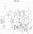
- the first heat exchanger heats the refrigerant of the heat pump cycle by using the cooling liquid having a comparatively high-temperature
- the second heat exchanger heats the heat medium by using the cooling liquid having a comparatively high temperature.
- the engine 2 is, for example, a gas engine that converts energy generated by burning 13A-town gas or the like into mechanical power.
- the engine 2 is connected to the compressor 5 via a transmission mechanism (not shown), such as a crank shaft or a belt drive device.
- a transmission mechanism such as a crank shaft or a belt drive device.
- the mechanical power generated by the engine 2 is transmitted to the compressor 5 to drive the compressor 5.
- Exhaust gas is generated when a fuel is burned in the engine 2.
- the exhaust gas is discharged to the outside of the engine 2.
- the exhaust gas generated by the engine 2 is led to the heater 6, cooled by exchanging heat with a working fluid flowing through the heater 6 in the Rankine cycle passage 3, and then discharged to external air.
- the engine 2 may be another machine that generates mechanical power by burning a gas fuel that is not town gas or by burning a liquid fuel, such as gasoline or heavy oil.
- the first heat exchanger 15 and the second heat exchanger 24 are parallelly disposed in the cooling liquid passage 7 downstream of a position (engine jacket 9) where the cooling liquid cools the engine 2 in the flow of the cooling liquid.
- the cooling liquid of the engine 2 can be used to heat either or both of the refrigerant flowing in the heat pump cycle passage 4 and the heat medium.
- the pipe that connects the flow divider valve 20 to the flow divider valve 23, a pipe that connects a cooling liquid inlet of the second heat exchanger 24 to the flow divider valve 23, and a pipe that connects a cooling liquid inlet of the second radiator 10 to the flow divider valve 23 are connected to the flow divider valve 23.
- a cooling liquid outlet of the first heat exchanger 15 is connected to a position in the cooling liquid passage 7 between a cooling liquid outlet of the second radiator 10 and the inlet of the cooling liquid pump 8.
- a cooling liquid outlet of the second heat exchanger 24 is connected to a position in the cooling liquid passage 7 between the cooling liquid outlet of the second radiator 10 and the inlet of the cooling liquid pump 8.
- water, oil, or a coolant is used as the heat medium that flows in the heat medium passage 26.
- the cooling liquid flowing in the cooling liquid passage 7 is heated by the engine 2 via the engine jacket 9.
- the cooling liquid passes through the flow divider valve 20 and is led to the flow divider valve 23.
- the heat pump cycle passage 4 need not receive the heat of the cooling liquid of the engine 2. Therefore, usually, the flow divider valve 20 is controlled so that the entire amount of the cooling liquid is led to the flow divider valve 23.
- the flow divider valve 20 may be controlled so that a part of the cooling liquid is led to the first heat exchanger 15. In such a case, the heat of the cooling liquid of the engine 2 is transferred to the refrigerant flowing in the heat pump cycle passage 4. Then, the outdoor heat exchanger 14 releases the heat.
- the flow divider valve 23 divides the flow of the cooling liquid that has passed through the flow divider valve 20 into, for example, a flow toward the second radiator 10 and a flow toward the second heat exchanger 24. If there is a demand for heating the heat medium by using the second heat exchanger 24, at least a part of the cooling liquid that has passed through the flow divider valve 20 is supplied to the second heat exchanger 24 as illustrated in Fig. 3A .
- the second heat exchanger 24 exchanges heat between the cooling liquid supplied thereto and the heat medium (for example, water) flowing in the heat medium passage 26, thereby cooling the cooling liquid.
- the second heat exchanger 24 heats the heat medium. If the heat medium is water, the temperature of hot water is increased.
- the flow divider valve 23 is controlled so that a large amount of cooling liquid flows toward the second heat exchanger 24. In some cases, the flow divider valve 23 may be controlled so that the entire amount of the cooling liquid that has passed through the flow divider valve 20 is led to the second heat exchanger 24. If demand for hot water is low, the flow divider valve 23 is controlled so that a large amount of cooling liquid flows toward the second radiator 10. If it is not necessary to heat the heat medium by using the second heat exchanger 24, the flow divider valve 23 may be controlled so that the entire amount of the cooling liquid that has passed through the flow divider valve 20 is led to the second radiator 10.
- the cooling liquid of the engine 2 which has a comparatively high temperature, is supplied to at least one of the first heat exchanger 15 and the second heat exchanger 24. Subsequently, the second radiator 10 releases heat from the cooling liquid of the engine 2. Therefore, the first heat exchanger 15 heats the refrigerant flowing in the heat pump cycle passage 4 by using the cooling liquid having a comparatively high temperature, or the second heat exchanger 24 heats the heat medium by using the cooling liquid having a comparatively high temperature.
- Patent Document 1 has room for increasing annual power output by using a Rankine cycle and room for improving power generation efficiency. In addition, the technology has room for reducing the size of the Rankine cycle.
- a second embodiment provides a Rankine cycle system that increases annual power output, that improves power generation efficiency, and that is advantageous in reduction in size.
- the inventors examined a Rankine cycle system that drives a compressor of a heat pump cycle, which is used for air conditioning, by using an engine and that operates a Rankine cycle by using exhaust heat from the engine, in order to enable the Rankin cycle system to perform year-round power generation.
- the inventors found that it is possible to perform year-round power generation and to increase annual power output by releasing heat of the working fluid discharged from the expander of the Rankine cycle to the cooling liquid for cooling the engine.
- the inventors found that it is possible to easily cool the working fluid and to easily improve the power generation efficiency by releasing heat of the working fluid of the Rankine cycle to the cooling liquid of the engine.
- the inventors found that it is possible to easily reduce the size of a radiator, which is to be disposed in the Rankine cycle, by releasing heat of the working fluid discharged from the expander of the Rankine cycle to the cooling liquid for cooling the engine.
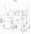
- the Rankine cycle system according to any one of the seventh to ninth aspects further includes an air-cooled radiator that is disposed in the Rankine cycle passage between an outlet of the expander and an inlet of the pump and that releases heat of the working fluid to external air.
- an air-cooled radiator that is disposed in the Rankine cycle passage between an outlet of the expander and an inlet of the pump and that releases heat of the working fluid to external air.
- the three-way valve 30 is capable of adjusting the flow rate of the cooling liquid supplied to the second radiator 10 and the first heat exchanger 15. For example, when a cooling operation is performed in the heat pump cycle passage 4, the three-way valve 30 is controlled so that the cooling liquid that has passed through the three-way valve 30 flows toward the second radiator 10. When a heating operation is performed in the heat pump cycle passage 4, the three-way valve 30 is controlled so that the cooling liquid that has passed through the three-way valve 30 flows toward the first heat exchanger 15. The first heat exchanger 15 exchanges heat between the cooling liquid and the refrigerant, thereby cooling the cooling liquid. The cooling liquid that has passed through the second radiator 10 or the first heat exchanger 15 is led to the third radiator 31.
- the compressor 5 is connected to the engine 2 via a power transmission mechanism, and the engine 2 drives the compressor 5.
- the compressor 5 is, for example, a positive-displacement compressor.
- Examples of the positive-displacement compressor includes a scroll compressor, a rotary compressor, a screw compressor, and a reciprocating compressor.
- the four pipes are connected to the four-way valve 11.
- the four pipes include a pair of inflow pipes through which a refrigerant flows into the four-way valve 11 and a pair of outflow pipes through which the refrigerant flows out of the four-way valve 11.
- the four-way valve 11 allows the refrigerant that has flowed into the four-way valve 11 through one of the pair of inflow pipes to flow out to one of the pair of outflow pipes; and the four-way valve 11 allows the refrigerant that has flowed into the four-way valve 11 through the other of the pair of inflow pipes to flow out to the other of the pair of outflow pipes.
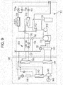
- the first heat exchanger 15 exchanges heat between the cooling liquid flowing in the cooling liquid passage 7 and the refrigerant flowing in the heat pump cycle passage 4, thereby heating the refrigerant.
- the position of the first heat exchanger 15 in the heat pump cycle passage 4 is not limited to a particular position.
- the heat pump cycle passage 4 is divided into two portions by the expansion valve 13 and the compressor, and the first heat exchanger 15 is disposed in one of the two portions that includes the outdoor heat exchanger 14. In this case, the first heat exchanger 15 is disposed, for example, between the refrigerant suction hole of the compressor 5 or the four-way valve 11 and the outdoor heat exchanger 14.
- Examples of a halogenated hydrocarbon that can be used as the organic working fluid that flows in the Rankine cycle passage 3 include R-134a, R-245fa, R-1234ze, and R-356mfc.
- Examples of a hydrocarbon that can be used as the organic working fluid that flows in the Rankine cycle passage 3 include propane, butane, pentane, and isopentane.
- One organic compound may be used as the organic working fluid, or a mixture of two or more organic compounds may be used as the organic working fluid.
- an inorganic compound such as water, carbon dioxide, or ammonia, may be used as the working fluid that flows in the Rankine cycle passage 3.
- the chain-line arrows represent flow of the refrigerant in the heat pump cycle passage 4
- the solid-line arrows represent flow of the working fluid in the Rankine cycle passage 3
- the two-dot-chain-line arrows represent flow of the cooling liquid in the cooling liquid passage 7.
Applications Claiming Priority (2)
| Application Number | Priority Date | Filing Date | Title |
|---|---|---|---|
| JP2016145398A JP2018017412A (ja) | 2016-07-25 | 2016-07-25 | ランキンサイクルシステム |
| JP2016145424A JP2018017132A (ja) | 2016-07-25 | 2016-07-25 | ランキンサイクルシステム |
Publications (1)
| Publication Number | Publication Date |
|---|---|
| EP3293372A1 true EP3293372A1 (fr) | 2018-03-14 |
Family
ID=59294924
Family Applications (1)
| Application Number | Title | Priority Date | Filing Date |
|---|---|---|---|
| EP17178970.4A Withdrawn EP3293372A1 (fr) | 2016-07-25 | 2017-06-30 | Système de cycle de rankine |
Country Status (1)
| Country | Link |
|---|---|
| EP (1) | EP3293372A1 (fr) |
Cited By (1)
| Publication number | Priority date | Publication date | Assignee | Title |
|---|---|---|---|---|
| CN111255595A (zh) * | 2018-11-30 | 2020-06-09 | 长城汽车股份有限公司 | 具有低压egr的发动机系统及车辆 |
Citations (5)
| Publication number | Priority date | Publication date | Assignee | Title |
|---|---|---|---|---|
| US4347702A (en) * | 1978-03-23 | 1982-09-07 | Co-Gen, Inc. | Power system |
| JP2012242015A (ja) | 2011-05-20 | 2012-12-10 | Aisin Seiki Co Ltd | エンジン駆動式空気調和装置 |
| FR3002279A1 (fr) * | 2013-02-20 | 2014-08-22 | Renault Sa | Systeme de recuperation de chaleur des gaz d'echappement dans un moteur a combustion interne |
| WO2015064302A1 (fr) * | 2013-10-30 | 2015-05-07 | いすゞ自動車株式会社 | Système de refroidissement de moteur |
| EP2930319A1 (fr) * | 2012-12-06 | 2015-10-14 | Panasonic Intellectual Property Management Co., Ltd. | Dispositif à cycle de rankine, système de cogénération et procédé de fonctionnement d'un dispositif à cycle de rankine |
-
2017
- 2017-06-30 EP EP17178970.4A patent/EP3293372A1/fr not_active Withdrawn
Patent Citations (5)
| Publication number | Priority date | Publication date | Assignee | Title |
|---|---|---|---|---|
| US4347702A (en) * | 1978-03-23 | 1982-09-07 | Co-Gen, Inc. | Power system |
| JP2012242015A (ja) | 2011-05-20 | 2012-12-10 | Aisin Seiki Co Ltd | エンジン駆動式空気調和装置 |
| EP2930319A1 (fr) * | 2012-12-06 | 2015-10-14 | Panasonic Intellectual Property Management Co., Ltd. | Dispositif à cycle de rankine, système de cogénération et procédé de fonctionnement d'un dispositif à cycle de rankine |
| FR3002279A1 (fr) * | 2013-02-20 | 2014-08-22 | Renault Sa | Systeme de recuperation de chaleur des gaz d'echappement dans un moteur a combustion interne |
| WO2015064302A1 (fr) * | 2013-10-30 | 2015-05-07 | いすゞ自動車株式会社 | Système de refroidissement de moteur |
Cited By (2)
| Publication number | Priority date | Publication date | Assignee | Title |
|---|---|---|---|---|
| CN111255595A (zh) * | 2018-11-30 | 2020-06-09 | 长城汽车股份有限公司 | 具有低压egr的发动机系统及车辆 |
| CN111255595B (zh) * | 2018-11-30 | 2021-06-18 | 长城汽车股份有限公司 | 具有低压egr的发动机系统及车辆 |
Similar Documents
| Publication | Publication Date | Title |
|---|---|---|
| JP5551508B2 (ja) | ランキンサイクルに従って動作する閉じた循環路内を循環する作動流体の制御装置及びその使用方法 | |
| US10364708B2 (en) | Rankine cycle apparatus, combined heat and power system, and rankine cycle apparatus operation method | |
| WO2013059687A1 (fr) | Moteur thermique et systèmes et procédés chaleur-électricité avec commande de la gestion de la masse de fluide de travail | |
| JP2006266238A (ja) | 膨張機付き流体ポンプおよびそれを用いたランキンサイクル | |
| JP5621721B2 (ja) | ランキンサイクル | |
| JP2005240740A (ja) | 車両用排熱回収システム | |
| US11300010B2 (en) | Cooling equipment, combined cycle plant comprising same, and cooling method | |
| WO2013046853A1 (fr) | Système de récupération de la chaleur perdue | |
| Shu et al. | Potential of a thermofluidic feed pump on performance improvement of the dual-loop Rankine cycle using for engine waste heat recovery | |
| JP2008127017A (ja) | 車両室内を空調するための冷却回路とランキン回路との組み合わせ | |
| JPWO2008139528A1 (ja) | 冷却サイクル系統、天然ガス液化設備、冷却サイクル系統の運転方法及び改造方法 | |
| EP3293372A1 (fr) | Système de cycle de rankine | |
| JP2010286135A (ja) | 熱供給システム | |
| JP4976426B2 (ja) | 冷凍サイクル系統、天然ガス液化設備、及び冷凍サイクル系統の改造方法 | |
| JP2005325746A (ja) | 車両用排熱回収システム | |
| JP2005273543A (ja) | 廃熱利用装置 | |
| EP3303781B1 (fr) | Procédé et appareil permettant d'abaisser la commande enthalpique de fluide actif cyclique dans un appareil de récupération de chaleur perdue | |
| JP5951593B2 (ja) | 排熱回収装置、排熱回収型船舶推進装置および排熱回収方法 | |
| US20190024538A1 (en) | Combined heat and power system and operating method of combined heat and power system | |
| KR102348113B1 (ko) | 폐열회수용 팽창장치 및 이를 포함하는 폐열회수시스템 | |
| JP6775185B2 (ja) | ランキンサイクルシステム及び発電方法 | |
| JP2006349211A (ja) | 複合サイクル装置およびその制御方法 | |
| JP2013160076A (ja) | ランキンサイクル装置 | |
| JP2018017132A (ja) | ランキンサイクルシステム | |
| JP2018017412A (ja) | ランキンサイクルシステム |
Legal Events
| Date | Code | Title | Description |
|---|---|---|---|
| PUAI | Public reference made under article 153(3) epc to a published international application that has entered the european phase |
Free format text: ORIGINAL CODE: 0009012 |
|
| AK | Designated contracting states |
Kind code of ref document: A1 Designated state(s): AL AT BE BG CH CY CZ DE DK EE ES FI FR GB GR HR HU IE IS IT LI LT LU LV MC MK MT NL NO PL PT RO RS SE SI SK SM TR |
|
| AX | Request for extension of the european patent |
Extension state: BA ME |
|
| 17P | Request for examination filed |
Effective date: 20180914 |
|
| RBV | Designated contracting states (corrected) |
Designated state(s): AL AT BE BG CH CY CZ DE DK EE ES FI FR GB GR HR HU IE IS IT LI LT LU LV MC MK MT NL NO PL PT RO RS SE SI SK SM TR |
|
| STAA | Information on the status of an ep patent application or granted ep patent |
Free format text: STATUS: THE APPLICATION HAS BEEN WITHDRAWN |
|
| 18W | Application withdrawn |
Effective date: 20190222 |