BACKGROUND
1. Technical Field
-
The present disclosure relates to a Rankine cycle system.
2. Description of the Related Art
-
To date, Rankin cycle systems that are equipped with a Rankine cycle device for generating electric power have been used. Examples of the Rankine cycle system include a system that operates a Rankin cycle device by using exhaust heat from an engine as a heat source.
-
For example,
Japanese Unexamined Patent Application Publication No. 2012-242015 (hereinafter referred to as Patent Document 1) describes an engine-driven air conditioner including a Rankine
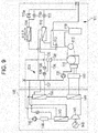
cycle circuit 140 shown in
Fig. 9. The engine-driven air conditioner includes an air-
conditioning circuit 111 and a cooling
liquid circuit 130. During a cooling operation, the Rankine
cycle circuit 140 heats a working fluid by using exhaust heat from a
gas engine 110 and recovers mechanical power. The Rankine
cycle circuit 140 includes a second
auxiliary heat exchanger 133, a
plate heat exchanger 141, an
expander 142, a Rankine
cycle radiator 143, a
receiver 144, and a
pump 145. The
expander 142 expands the working fluid that has passed through the
plate heat exchanger 141 and generates mechanical power. A
generator 146 is mechanically connected to the
expander 142, and the
generator 146 converts mechanical energy (mechanical power) generated by the
expander 142 into electrical energy. The working fluid that has flowed out of the
expander 142 is condensed in the Rankine
cycle radiator 143 by exchanging heat with outdoor air.
-
The air-conditioning circuit 111 forms a channel along which a refrigerant discharged from a compressor 112, which is driven by the gas engine 110, flows until the refrigerant is sucked into the compressor 112. The air-conditioning circuit 111 includes a four-way valve 113, an outdoor unit heat exchanger 114, a check valve 115a, an electronic expansion valve 115b, an expansion valve, an indoor unit heat exchanger, a first auxiliary heat exchanger 116, an electronic expansion valve 117, and an accumulator 118. The first auxiliary heat exchanger 116 and the second auxiliary heat exchanger 133 are disposed in a first cooling liquid supply passage 136 and a second cooling liquid supply passage 137, each of which is capable of supplying a cooling liquid and which are independent from each other. A first electronic expansion valve 138 and a second electronic expansion valve 139 are disposed in the first cooling liquid supply passage 136 and the second cooling liquid supply passage 137.
-
The cooling liquid circuit 130 includes a water pump 131, the first auxiliary heat exchanger 116, the second auxiliary heat exchanger 133, a thermostat 135, and the like. The cooling liquid circuit 130 includes a bypass channel 134.
-
During a cooling operation, if the cooling liquid temperature T is higher than a lower temperature T1 and lower than or equal to a higher temperature T2, a cooling liquid, which has been pumped by the water pump 131 and passed through the gas engine 110, mainly flows through the second auxiliary heat exchanger 133 and returns to the water pump 131. In this case, the second auxiliary heat exchanger 133 uses exhaust heat from the gas engine 110 to increase the pressure of the working fluid of the Rankine cycle circuit 140 via the cooling liquid. As a result, the mechanical-power-recovery efficiency of the Rankine cycle circuit 140 is improved.
-
During a heating operation, if the cooling liquid temperature T is higher than the lower temperature T1 and lower than or equal to the higher temperature T2, the cooling liquid, which has been pumped by the water pump 131 and passed through the gas engine 110, flows through the first auxiliary heat exchanger 116 and returns to the water pump 131. In this case, the first auxiliary heat exchanger 116 uses exhaust heat from the gas engine 110 to heat and evaporate the refrigerant of the air-conditioning circuit 111 via the cooling liquid. As a result, the heating efficiency of the air-conditioning circuit 111 is improved. During a heating operation, if the cooling liquid temperature T is higher than the higher temperature T2, the Rankine cycle radiator 143, which is in an unused state, releases heat from the cooling liquid to the outside. Thus, exhaust heat from the gas engine 110 is released to the outside.
SUMMARY
-
The technology described in Patent Document 1 has room for improvement in exhaust-heat utilization efficiency while enabling year-round power generation using a Rankine cycle.
-
One non-limiting and exemplary embodiment provides a Rankine cycle system that is capable of performing year-round power generation by using a Rankine cycle and that is advantageous in improving exhaust-heat utilization efficiency.
-
In one general aspect, the techniques disclosed here feature a Rankine cycle system including a heat pump cycle passage in which a refrigerant flows; a Rankine cycle passage in which a working fluid flows; a cooling liquid passage in which a cooling liquid flows; a compressor that is disposed in the heat pump cycle passage and that compresses the refrigerant; an engine that is connected to the compressor to drive the compressor and that is cooled by the cooling liquid flowing in the cooling liquid passage; a pump that is disposed in the Rankine cycle passage and that pumps the working fluid; a heater that is disposed in the Rankine cycle passage and that heats the working fluid pumped by the pump by using exhaust heat from the engine; and an expander that is disposed in the Rankine cycle passage and that expands the working fluid heated by the heater.
-
The Rankine cycle system is capable of performing year-round power generation by using the Rankine cycle and is advantageous in improving exhaust-heat utilization efficiency.
-
It should be noted that general or specific embodiments may be implemented as a system, a method, an integrated circuit, a computer program, a storage medium or any selective combination thereof.
-
Additional benefits and advantages of the disclosed embodiments will become apparent from the specification and drawings. The benefits and/or advantages may be individually obtained by the various embodiments and features of the specification and drawings, which need not all be provided in order to obtain one or more of such benefits and/or advantages.
BRIEF DESCRIPTION OF THE DRAWINGS
-
- Fig. 1 illustrates an example of a Rankine cycle system according to a first embodiment of the present disclosure;
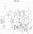
- Fig. 2A illustrates the Rankine cycle system of Fig. 1 during a cooling operation;
- Fig. 2B illustrates of the Rankine cycle system of Fig. 1 during a heating operation;
- Fig. 3A illustrates the Rankine cycle system of Fig. 1 when heating a heat medium;
- Fig. 3B illustrates the Rankine cycle system of Fig. 1 when heating a refrigerant;
- Fig. 4 illustrates a Rankine cycle system according to a modification;
- Fig. 5 illustrates a Rankine cycle system according to another modification;
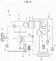
- Fig. 6 illustrates an example of a Rankine cycle system according to a second embodiment of the present disclosure;
- Fig. 7A illustrates the Rankine cycle system of Fig. 6 during a cooling operation;
- Fig. 7B illustrates the Rankine cycle system of Fig. 6 during a heating operation;
- Fig. 8 illustrates a Rankine cycle system according to a modification; and
- Fig. 9 illustrates an engine-driven air conditioner including an existing Rankine cycle circuit.
DETAILED DESCRIPTION
First Embodiment
Underlying Knowledge Forming Basis of the Present Disclosure
-
The inventors examined a Rankine cycle system that drives a compressor of a heat pump cycle, which is used for air conditioning, by using an engine and that operates a Rankine cycle by using exhaust heat from the engine, in order to enable the Rankin cycle system to perform year-round power generation. In addition, the inventors examined how to improve the exhaust-heat utilization efficiency of the Rankine cycle system. As a result, the inventors found providing a heat medium passage and enabling heat exchange between a cooling liquid for cooling the engine and a refrigerant of the heat pump cycle. In addition, the inventors found enabling heat exchange between the cooling liquid for cooling the engine and a heat medium while enabling a working fluid, which has been expanded by the expander, to release heat of a working fluid to the heat medium. Thus, the inventors found that it is possible to provide a Rankine cycle system that is capable of performing year-round power generation and that is advantageous in improving exhaust-heat utilization efficiency.
-
Based on such new findings, the inventors devised a Rankine cycle system according to the present disclosure. With the technology described in Patent Document 1, during a cooling operation, the Rankine cycle radiator 143 releases exhaust heat from the Rankine cycle circuit 140 to outdoor air. Therefore, exhaust heat from the Rankine cycle circuit 140 is not efficiently used. During a heating operation, the Rankine cycle radiator 143 releases exhaust heat from the gas engine 110 that is not used by the air-conditioning circuit 111 from the cooling liquid to the outside (outdoor air). Therefore, during the heating operation, exhaust heat from the gas engine 110 is not efficiently used and the Rankine cycle circuit 140 cannot be operated. Thus, the technology described in Patent Document 1 has a problem in that the technology is not capable of efficiently using exhaust heat from the Rankine cycle circuit 140 and exhaust heat from the gas engine 110.
-
According to a first aspect of the present disclosure, a Rankine cycle system includes:
- a heat pump cycle passage in which a refrigerant flows;
- a Rankine cycle passage in which a working fluid flows;
- a cooling liquid passage in which a cooling liquid flows;
- a compressor that is disposed in the heat pump cycle passage and that compresses the refrigerant;
- an engine that is connected to the compressor to drive the compressor and that is cooled by the cooling liquid flowing in the cooling liquid passage;
- a pump that is disposed in the Rankine cycle passage and that pumps the working fluid;
- a heater that is disposed in the Rankine cycle passage and that heats the working fluid pumped by the pump by using exhaust heat from the engine; and
- an expander that is disposed in the Rankine cycle passage and that expands the working fluid heated by the heater.
-
According to a second aspect of the present disclosure, the Rankine cycle system according to first aspect further includes:
- a heat medium passage in which a heat medium flows;
- a first heat exchanger that is disposed in the cooling liquid passage and the heat pump cycle passage and that exchanges heat between the cooling liquid and the refrigerant;
- a second heat exchanger that is disposed in the cooling liquid passage and the heat medium passage and that exchanges heat between the cooling liquid and the heat medium; and
- a first radiator that is disposed in the Rankine cycle passage and the heat medium passage and that releases heat of the working fluid expanded in the expander to the heat medium.
-
With the second aspect, the first radiator can recover exhaust heat from the Rankine cycle by using the heat medium. Thus, exhaust heat from the Rankine cycle can be recovered by using the heat medium, and the amount of recovered exhaust heat is large. Moreover, the first heat exchanger can exchange heat between the cooling liquid of the engine and the refrigerant of the heat pump cycle; and the second heat exchanger can exchange heat between the cooling liquid of the engine and the heat medium. Therefore, exhaust heat from the engine can be used to heat the refrigerant flowing in the heat pump cycle passage and to heat the heat medium. Therefore, it is possible to increase the amount of exhaust heat from the Rankine cycle that is recovered while performing power generation by using the Rankine cycle and to improve the efficiency of utilizing exhaust heat from the engine. Moreover, heat of the heat medium heated by exhaust heat from the Rankine cycle can be released to the cooling liquid of the engine, and exhaust heat from the Rankine cycle can be used to heat the refrigerant flowing in the heat pump cycle passage. Furthermore, the Rankine cycle can be operated during a heating operation, and therefore it is possible to perform year-round power generation by using the Rankine cycle.
-
According to a third aspect of the present disclosure, in the Rankine cycle system according to the second aspect, the first heat exchanger and the second heat exchanger are parallelly disposed in the cooling liquid passage downstream of a position where the cooling liquid cools the engine in a flow of the cooling liquid. With the third aspect, the cooling liquid of the engine can be used to heat either or both of the refrigerant flowing in the heat pump cycle passage and the heat medium. When the first heat exchanger heats the refrigerant flowing in the heat pump cycle passage by using the cooling liquid of the engine and the second heat exchanger heats the heat medium by using the cooling liquid of the engine, the temperature of the cooling liquid supplied to the first heat exchanger and the temperature of the cooling liquid supplied to the second heat exchanger become substantially the same as each other. Therefore, it is possible to supply a cooling liquid having a stable temperature to the first heat exchanger and the second heat exchanger and to enhance the use of exhaust heat. Thus, the efficiency of utilizing exhaust heat from the engine can be improved easily.
-
According to a fourth aspect of the present disclosure, in the Rankine cycle system according to the second aspect, the first heat exchanger and the second heat exchanger are serially disposed downstream of a position where the cooling liquid cools the engine in a flow of the cooling liquid, and a cooling liquid outlet of the first heat exchanger is located upstream of a cooling liquid inlet of the second heat exchanger in the flow of the cooling liquid. With the fourth aspect, the cooling liquid that has passed through the first heat exchanger is supplied to the second heat exchanger. Therefore, the temperature of the cooling liquid supplied to second heat exchanger is low. Therefore, the second heat exchanger can easily heat the cooling liquid by using the heat medium. The cooling liquid heated by the second heat exchanger cools the engine, and then the cooling liquid is supplied to the first heat exchanger. Therefore, it is possible to easily use exhaust heat from the Rankine cycle to heat the refrigerant flowing in the heat pump cycle passage via the heat medium and the cooling liquid.
-
According to a fifth aspect of the present disclosure, the Rankine cycle system according to any one of the second to fourth aspects further includes a second radiator that is disposed in the cooling liquid passage downstream of a position where the cooling liquid cools the engine in a flow of the cooling liquid and that releases heat of the cooling liquid. At least one of the first heat exchanger and the second heat exchanger is disposed in the cooling liquid passage between the position where the cooling liquid cools the engine and a cooling liquid inlet of the second radiator. With the fifth aspect, the cooling liquid of the engine, having a comparatively high-temperature, is supplied to at least one of the first heat exchanger and the second heat exchanger. Subsequently, the second radiator releases the heat of the cooling liquid of the engine. Therefore, the first heat exchanger heats the refrigerant of the heat pump cycle by using the cooling liquid having a comparatively high-temperature, or the second heat exchanger heats the heat medium by using the cooling liquid having a comparatively high temperature. Thus, for example, it is easy to increase the temperature of the refrigerant sucked into the compressor, or it is possible to respond to demand for high-temperature heat medium and to enhance the use of exhaust heat. As a result, the efficiency of utilizing exhaust heat from the engine can be easily improved while performing power generation by using the Rankine cycle.
-
According to a sixth aspect of the present disclosure, the Rankine cycle system according to any one of the second to fifth aspects further includes an air-cooled radiator that is disposed in the Rankine cycle passage between an outlet of the expander and an inlet of the pump and that releases heat of the working fluid to external air. With the sixth aspect, when the demand for the heat medium is zero or small, the Rankine cycle can generate a large amount of electric power, because the air-cooled radiator releases heat of the working fluid. By using the air-cooled radiator in this way, it is possible to increase the amount of electric power generated by the Rankine cycle while reducing the amount of exhaust heat from the Rankine cycle recovered by using the heat medium. As a result, it is possible to change the ratio of the amount of energy of the working fluid of the Rankine cycle that is used as electrical energy to the amount of heat energy of the working fluid of the Rankine cycle that is recovered by the heat medium. Thus, the efficiency of utilizing exhaust heat from the engine can be increased more easily.
-
Hereinafter, a first embodiment of the present disclosure will be described with reference to the drawings. Note that the present disclosure is not limited to the following description.
-
Referring to Fig. 1, a Rankine cycle system 1a includes a heat pump cycle passage 4, a Rankine cycle passage 3, a cooling liquid passage 7, a heat medium passage 26, a compressor 5, an engine 2, a first heat exchanger 15, a second heat exchanger 24, a pump 17, a heater 6, an expander 16, and a first radiator 22. The heat pump cycle passage 4 is a passage in which a refrigerant flows. The Rankine cycle passage 3 is a passage in which a working fluid flows. The cooling liquid passage 7 is a passage in which a cooling liquid flows. The heat medium passage 26 is a passage in which a heat medium flows. The compressor 5 is disposed in the heat pump cycle passage 4 and compresses the refrigerant. The engine 2 is connected to the compressor 5 to drive the compressor 5. The engine 2 is cooled by the cooling liquid flowing in the cooling liquid passage 7. The first heat exchanger 15 is disposed in the cooling liquid passage 7 and the heat pump cycle passage 4 and exchanges heat between the cooling liquid and the refrigerant. The second heat exchanger 24 is disposed in the cooling liquid passage 7 and the heat medium passage 26 and exchanges heat between the cooling liquid and the heat medium. The pump 17 is disposed in the Rankine cycle passage 3 and pumps the working fluid. The heater 6 is disposed in the Rankine cycle passage 3 and heats the working fluid, which has been pumped by the pump 17, by using exhaust heat from the engine 2. The expander 16 is disposed in the Rankine cycle passage 3 and expands the working fluid heated by the heater 6. The first radiator 22 is disposed in the Rankine cycle passage 3 and the heat medium passage 26 and releases heat of the working fluid, which has been expanded by the expander 16, to the heat medium.
-
The engine 2 is, for example, a gas engine that converts energy generated by burning 13A-town gas or the like into mechanical power. The engine 2 is connected to the compressor 5 via a transmission mechanism (not shown), such as a crank shaft or a belt drive device. Thus, the mechanical power generated by the engine 2 is transmitted to the compressor 5 to drive the compressor 5. Exhaust gas is generated when a fuel is burned in the engine 2. The exhaust gas is discharged to the outside of the engine 2. For example, the exhaust gas generated by the engine 2 is led to the heater 6, cooled by exchanging heat with a working fluid flowing through the heater 6 in the Rankine cycle passage 3, and then discharged to external air. The engine 2 may be another machine that generates mechanical power by burning a gas fuel that is not town gas or by burning a liquid fuel, such as gasoline or heavy oil.
-
The cooling liquid passage 7 is a passage in which the cooling liquid for cooing the engine 2 flows. Referring to Fig. 1, the Rankine cycle system 1a further includes, for example, a second radiator 10. The second radiator 10 is disposed in the cooling liquid passage 7 downstream of a position where the cooling liquid cools the engine 2 in the flow of the cooling liquid. The second radiator 10 releases heat of the cooling liquid.
-
In the cooling liquid passage 7, for example, a cooling liquid pump 8, an engine jacket 9, and the second radiator 10 are disposed. These components are sequentially connected in a loop shape through pipes so as to form a closed circuit. The cooling liquid, which is pumped by the cooling liquid pump 8, absorbs heat generated by the engine 2 while passing through the engine jacket 9. The second radiator 10 releases the heat of the cooling liquid to external air. Subsequently, the cooling liquid returns to the cooling liquid pump 8. The temperature of the engine 2 is maintained in a desirable range, because the cooling liquid cools engine 2 via the engine jacket 9.
-
Referring to Fig. 1, the first heat exchanger 15 and the second heat exchanger 24 are parallelly disposed in the cooling liquid passage 7 downstream of a position (engine jacket 9) where the cooling liquid cools the engine 2 in the flow of the cooling liquid. Thus, the cooling liquid of the engine 2 can be used to heat either or both of the refrigerant flowing in the heat pump cycle passage 4 and the heat medium. When the first heat exchanger 15 heats the refrigerant flowing in the heat pump cycle passage 4 by using the cooling liquid of the engine 2 and the second heat exchanger 24 heats the heat medium by using the cooling liquid of the engine 2, the temperature of the cooling liquid supplied to the first heat exchanger 15 and the temperature of the cooling liquid supplied to the second heat exchanger 24 become substantially the same as each other.
-
For example, a flow divider valve 20 and a flow divider valve 23 are disposed in the cooling liquid passage 7. The flow divider valve 20 and the flow divider valve 23 are disposed, for example, in the cooling liquid passage 7 between an outlet of the engine jacket 9 and an inlet of the cooling liquid pump 8. For example, the flow divider valve 23 is disposed in the cooling liquid passage 7 downstream of the flow divider valve 20 in the flow of the cooling liquid. A pipe that connects the outlet of the engine jacket 9 to the flow divider valve 20, a pipe that connects a cooling liquid inlet of the first heat exchanger 15 to the flow divider valve20, and a pipe that connects the flow divider valve 23 to the flow divider valve 20 are connected to the flow divider valve20. The pipe that connects the flow divider valve 20 to the flow divider valve 23, a pipe that connects a cooling liquid inlet of the second heat exchanger 24 to the flow divider valve 23, and a pipe that connects a cooling liquid inlet of the second radiator 10 to the flow divider valve 23 are connected to the flow divider valve 23. A cooling liquid outlet of the first heat exchanger 15 is connected to a position in the cooling liquid passage 7 between a cooling liquid outlet of the second radiator 10 and the inlet of the cooling liquid pump 8. A cooling liquid outlet of the second heat exchanger 24 is connected to a position in the cooling liquid passage 7 between the cooling liquid outlet of the second radiator 10 and the inlet of the cooling liquid pump 8.
-
For example, a cooling liquid that has flowed out of the engine jacket 9 flows through the flow divider valve 20 toward at least one of the first heat exchanger 15 and the flow divider valve 23. When the cooling liquid is supplied to the first heat exchanger 15, the cooling liquid flowing in the cooling liquid passage 7 and the refrigerant flowing in the heat pump cycle passage 4 exchange heat. Thus, the refrigerant is heated and the cooling liquid is cooled. The cooling liquid that has passed through the first heat exchanger 15 is led to a position in the cooling liquid passage 7 between the cooling liquid outlet of the second radiator 10 and the inlet of the cooling liquid pump 8.
-
The cooling liquid that has passed through the flow divider valve 20 and flowed toward the flow divider valve 23 passes through the flow divider valve 23 and flows toward at least one of the second heat exchanger 24 and the second radiator 10. When the cooling liquid is supplied to the second heat exchanger 24, the cooling liquid flowing in the cooling liquid passage 7 and the heat medium flowing in the heat medium passage 26 exchange heat. Thus, if the temperature of the cooling liquid is higher than the temperature of the heat medium, the heat medium is heated and the cooling liquid is cooled. If the temperature of the cooling liquid is lower than the temperature of the heat medium, the cooling liquid is heated and the heat medium is cooled. The cooling liquid that has passed through the second heat exchanger 24 is led to a position in the cooling liquid passage 7 between the cooling liquid outlet of the second radiator 10 and the inlet of the cooling liquid pump 8.
-
Each of the first heat exchanger 15 and the second heat exchanger 24 is an existing heat exchanger, such as a plate heat exchanger or a double-pipe heat exchanger.
-
The flow divider valve 20 and the flow divider valve 23 are, for example, flow control valves that can adjust the flow rate of the cooling liquid supplied to the first heat exchanger 15 and the second heat exchanger 24. Each of the flow divider valve 20 and the flow divider valve 23 is an existing flow control valve, such as a needle valve. Each of the flow divider valve 20 and the flow divider valve 23 may be an on-off valve, such as a ball valve.
-
Referring to Fig. 1, for example, the compressor 5, a four-way valve 11, an indoor heat exchanger 12, an expansion valve 13, and an outdoor heat exchanger 14 are disposed in the heat pump cycle passage 4. These components are sequentially connected in a loop shape through pipes so as to form a closed circuit.
-
As described above, the compressor 5 is connected to the engine 2 via a power transmission mechanism, and the engine 2 drives the compressor 5. The compressor 5 is, for example, a positive-displacement compressor. Examples of the positive-displacement compressor includes a scroll compressor, a rotary compressor, a screw compressor, and a reciprocating compressor.
-
Four pipes are connected to the four-way valve 11. The four pipes include a pair of inflow pipes through which a refrigerant flows into the four-way valve 11 and a pair of outflow pipes through which the refrigerant flows out of the four-way valve 11. The four-way valve 11 allows the refrigerant that has flowed into the four-way valve 11 through one of the pair of inflow pipes to flow out to one of the pair of outflow pipes; and the four-way valve 11 allows the refrigerant that has flowed into the four-way valve 11 through the other of the pair of inflow pipes to flow out to the other of the pair of outflow pipes. The four-way valve 11 is capable of changing the direction (channel) in which the refrigerant flows out of the four-way valve 11 by switching the flow path inside the four-way valve 11. For example, the four pipes connected to the four-way valve 11 include a first pipe, a second pipe, a third pipe, and a fourth pipe. The first pipe forms at a least a part of the heat pump cycle passage 4 that connects a refrigerant discharge hole of the compressor 5 to the four-way valve 11. The second pipe forms at a least a part of the heat pump cycle passage 4 that connects the four-way valve 11 to the indoor heat exchanger 12. The third pipe forms at a least a part of the heat pump cycle passage 4 that connects the four-way valve 11 to the outdoor heat exchanger 14. The fourth pipe forms at a least a part of the heat pump cycle passage 4 that connects the four-way valve 11 to a refrigerant suction hole of the compressor 5. The four-way valve 11 is capable of selectively switching between a state A and a state B by switching between the channels therein. The state A is a state in which the four-way valve 11 connects the inside of the first pipe to the inside of the second pipe and connects the inside of the third pipe to the inside of the fourth pipe. The state B is a state in which the four-way valve 11 connects the inside of the first pipe to the inside of the third pipe and connects the inside of the second pipe to the inside of the fourth pipe.
-
The indoor heat exchanger 12 is disposed, for example, inside of a building. The indoor heat exchanger 12 exchanges heat between the refrigerant flowing in the heat pump cycle passage 4 and indoor air, thereby cooling or heating the refrigerant. An existing heat exchanger, such as a finned-tube heat exchanger, can be used as the indoor heat exchanger 12. When the refrigerant flowing in the heat pump cycle passage 4 passes through the expansion valve 13, the refrigerant is depressurized and expanded and the pressure and the temperature of the refrigerant decrease. The outdoor heat exchanger 14 is disposed, for example, outside of a building. The outdoor heat exchanger 14 exchanges heat between the refrigerant flowing in the heat pump cycle passage 4 and external air, thereby cooling or heating the refrigerant. An existing heat exchanger, such as a finned-tube heat exchanger, can be used as the outdoor heat exchanger 14.
-
The first heat exchanger 15 exchanges heat between the cooling liquid flowing in the cooling liquid passage 7 and the refrigerant flowing in the heat pump cycle passage 4, thereby heating the refrigerant. The position of the first heat exchanger 15 in the heat pump cycle passage 4 is not limited to a particular position. The heat pump cycle passage 4 is divided into two portions by the compressor 5 and the expansion valve 13, and the first heat exchanger 15 is disposed in one of the two portions that includes a refrigerant channel of the outdoor heat exchanger 14. In this case, the first heat exchanger 15 is disposed, for example, between the refrigerant suction hole of the compressor 5 or the four-way valve 11 and the outdoor heat exchanger 14.
-
Referring to Fig. 1, for example, the Rankine cycle system 1 a further includes an air-cooled radiator 19. The air-cooled radiator 19 is disposed between an outlet of the expander 16 and an inlet of the pump 17 in the Rankine cycle passage 3 and releases heat of the working fluid to external air.
-
Referring to Fig. 1, for example, in the Rankine cycle passage 3, the expander 16, the first radiator 22, the pump 17, and the heater 6 are sequentially connected in a loop shape so as to form a closed circuit. For example, the air-cooled radiator 19 and the first radiator 22 are parallelly disposed. For example, a flow divider valve 25 is disposed in the Rankine cycle passage 3 between the outlet of the expander 16 and a working fluid inlet of the first radiator 22. A pipe that connects the outlet of the expander 16 to the flow divider valve 25, a pipe that connects the working fluid inlet of the first radiator 22 to the flow divider valve 25, and a pipe that connects the working fluid inlet of the air-cooled radiator 19 to the flow divider valve 25 are connected to the flow divider valve 25. The working fluid outlet of the air-cooled radiator 19 is connected to a portion of the Rankine cycle passage 3 between the working fluid outlet of the first radiator 22 and the inlet of the pump 17.
-
The expander 16 converts the energy of the working fluid into rotational power by expanding the working fluid. A generator 21 is connected to the rotary shaft of the expander 16, and the expander 16 drives the generator 21. The expander 16 is, for example, a positive-displacement expander or a velocity-type expander. Examples of a positive-displacement expander that can be used as the expander 16 include a scroll expander, a rotary expander, a screw expander, and a reciprocating expander. Examples of a velocity-type expander that can be used as the expander 16 include an expansion turbine.
-
Preferably, the expander 16 is a positive-displacement expander. Typically, a positive-displacement expander has high expander efficiency in a rotation speed range wider than that of a velocity-type expander. For example, a positive-displacement expander can be operated at a rotation speed lower than or equal to a half of the rated rotation speed while maintaining high expander efficiency. That is, it is possible to reduce power generation amount to a level lower than or equal to a half of the rated power generation amount while maintaining high expander efficiency. By using the positive-displacement expander having such characteristics as the expander 16, the Rankine cycle system 1a can satisfy a need for flexibly changing the power generation amount in response to a change in heat demand. In addition, by using a positive-displacement expander as the expander 16, it is possible to change the power generation amount in response to a change in electric power demand while maintaining high expander efficiency.
-
The first radiator 22 exchanges heat between the working fluid discharged from the expander 16 and the heat medium flowing in the heat medium passage 26, thereby cooling the working fluid and heating the heat medium. The first radiator 22 is an existing heat exchanger, such as a plate heat exchanger or a double-pipe heat exchanger.
-
The air-cooled radiator 19 releases, to external air, heat of the working fluid that has been discharged from the expander 16 and passed through the flow divider valve 25 toward the air-cooled radiator 19. Thus, the working fluid is cooled. The air-cooled radiator 19 is an existing heat exchanger, such as a finned-tube heat exchanger.
-
The pump 17 sucks the working fluid that has flowed out of the first radiator 22 or the air-cooled radiator 19 thereinto and pumps the working fluid toward the heater 6. A positive-displacement pump or a velocity-type pump can be used as the pump 17. Examples of a positive-displacement pump that can be used as the pump 17 include a piston pump, a gear pump, a vane pump, and a rotary pump. Examples of a velocity-type pump that can be used as the pump 17 include a centrifugal pump, a mixed flow pump, and an axial flow pump.
-
The heater 6 is a heat exchanger that absorbs heat energy of exhaust gas generated in the engine 2. An existing heat exchanger, such as a plate heat exchanger or a finned-tube heat exchanger, can be used as the heater 6. The heater 6 exchanges heat between the exhaust gas supplied from the engine 2 and the working fluid flowing in the Rankine cycle passage 3. Thus, the working fluid flowing in the Rankine cycle passage 3 is heated and evaporated.
-
Preferably, the working fluid flowing in the Rankine cycle passage 3 is an organic working fluid made of a predetermined organic compound. In many cases, the boiling point of an organic working fluid is low. Therefore, by using an organic working fluid as the working fluid that flows in the Rankine cycle passage 3, the Rankine cycle system 1a can generate electric power with high efficiency even when the temperature of exhaust gas supplied from the engine 2 is in the range of about 200°C to 400°C. An organic compound, such as a halogenated hydrocarbon or a hydrocarbon, can be used as the organic working fluid that flows in the Rankine cycle passage 3. Examples of a halogenated hydrocarbon that can be used as the organic working fluid that flows in the Rankine cycle passage 3 include R-134a, R-245fa, R-1234ze, and R-356mfc. Examples of a hydrocarbon that can be used as the organic working fluid that flows in the Rankine cycle passage 3 include propane, butane, pentane, and isopentane. One organic compound may be used as the organic working fluid, or a mixture of two or more organic compounds may be used as the organic working fluid. In some cases, an inorganic compound, such as water, carbon dioxide, or ammonia, may be used as the working fluid that flows in the Rankine cycle passage 3.
-
The heat medium that flows in the heat medium passage 26 is, for example, water. For example, hot water is generated while water passes through the heat medium passage 26, and the hot water is supplied through the heat medium passage 26 to be used as it is or to be used for heating air. In the heat medium passage 26, a pump (not shown), the first radiator 22, the second heat exchanger 24, and a hot water tank (not shown) are disposed. These components are sequentially connected in a loop shape through pipes so as to form a closed circuit.
-
While water that has been discharged from the pump (not shown) disposed in the heat medium passage 26 passes through the first radiator 22, the water absorbs heat of the working fluid flowing in the Rankine cycle passage 3. Moreover, while the water passes through the second heat exchanger 24, the water exchanges heat with the cooling liquid flowing in the cooling liquid passage 7. Subsequently, hot water that has passed through the second heat exchanger 24 flows into the hot water tank (not shown) to be stored. The hot water stored in the hot water tank is supplied to be used as it is or to be used for heating air so as to respond to heat demand. When the heat medium passes through the second heat exchanger 24, the heat medium is heated if the temperature of the cooling liquid supplied to the second heat exchanger 24 is higher than the temperature of the heat medium. The heat medium is cooled if the temperature of the cooling liquid supplied to the second heat exchanger 24 is lower than the temperature of the heat medium.
-
For example, water, oil, or a coolant is used as the heat medium that flows in the heat medium passage 26.
-
An exemplary operation of the Rankine cycle system 1 a will be described. When the pump 17 of the Rankine cycle passage 3 pumps the working fluid, the working fluid is pressurized and flows into the heater 6. When the engine 2 is operating, the heater 6 exchanges heat between the working fluid flowing in the Rankine cycle passage 3 and exhaust gas generated in the engine 2, thereby heating and evaporating the working fluid. Thus, the working fluid becomes a high-temperature and high-pressure vapor. The high-temperature and high-pressure working fluid that has flowed out of the heater 6 flows into the expander 16. The expander 16 converts the pressure energy of the working fluid into mechanical energy to drive the generator 21. Thus, the generator 21 generates electric power. The working fluid discharged from the expander 16 passes through the flow divider valve 25 and flows into the first radiator 22. The first radiator 22 releases the heat of the working fluid, which has been expanded by the expander, to the heat medium (for example, water) flowing in the heat medium passage 26. Thus, the working fluid is cooled and condensed.
-
If the first radiator 22 is not capable of sufficiently cooling the working fluid by using the heat medium flowing in the heat medium passage 26, the flow divider valve 25 may be controlled so that a part of the working fluid is led to the air-cooled radiator 19, and the air-cooled radiator 19 may release heat of the part of the working fluid. By doing so, as necessary, it is possible to make up for the deficiency in the ability of the first radiator 22 to cool the working fluid. The working fluid that has flowed out of the first radiator 22 and the air-cooled radiator 19 becomes a low-temperature and low-pressure liquid and is led to the pump 17. Electric power generated by the generator 21 is consumed in, for example, the heat pump cycle passage 4, the engine 2, and the Rankine cycle passage 3. In some cases, flow of electric power generated by the generator 21 may be reversed by using a power converter in order to sell the electric power to an electric power company.
-
Next, an exemplary operation of the Rankine cycle system 1a when a cooling operation is performed in the heat pump cycle passage 4 will be described. Referring to Fig. 2A, during the cooling operation, the engine 2 rotates the compressor 5 and the compressor 5 sucks a refrigerant thereinto, and thereby the refrigerant is compressed to become a high-temperature and high-pressure vapor and led to the four-way valve 11. During the cooling operation, the four-way valve 11 is in the state B. The refrigerant, which has been discharged from the compressor 5, passes through the four-way valve 11 and the first heat exchanger 15, and flows into the outdoor heat exchanger 14. The outdoor heat exchanger 14 exchanges heat between the refrigerant and external air, and thereby the refrigerant becomes a low-temperature and high-pressure refrigerant and is led to the expansion valve 13. The expansion valve 13 decompresses and expands the refrigerant, and thereby the refrigerant becomes a low-temperature and low-pressure refrigerant. Subsequently, the refrigerant is supplied to the indoor heat exchanger 12. The indoor heat exchanger 12 exchanges heat between the refrigerant and indoor air, thereby heating the refrigerant. Thus, the indoor air is cooled and the indoor space is cooled. The refrigerant, which has passed through the indoor heat exchanger 12, passes through the four-way valve 11 and flows into the compressor 5 from the suction hole of the compressor 5. In Figs. 2A, 2B, 3A, and 3B, the chain-line arrows represent flow of the refrigerant in the heat pump cycle passage 4, the solid-line arrows represent flow of the working fluid in the Rankine cycle passage 3, the two-dot-chain-line arrows represent flow of the cooling liquid in the cooling liquid passage 7, and the broken-line arrows represent flow of the heat medium in the heat medium passage 26.
-
Referring to Fig. 2A, in the first radiator 22, the heat medium flowing in the heat medium passage 26 absorbs heat of the working fluid flowing in the Rankine cycle passage 3. Moreover, in the second heat exchanger 24, the heat medium absorbs heat of the cooling liquid of the engine 2 flowing in the cooling liquid passage 7. Thus, for example, hot water is generated.
-
Referring to Fig. 2A, the cooling liquid flowing in the cooling liquid passage 7 is heated by the engine 2 via the engine jacket 9. The cooling liquid passes through the flow divider valve 20 and is led to the flow divider valve 23. During the cooling operation, the heat pump cycle passage 4 need not receive the heat of the cooling liquid of the engine 2. Therefore, usually, the flow divider valve 20 is controlled so that the entire amount of the cooling liquid is led to the flow divider valve 23. In some cases, during a cooling operation, the flow divider valve 20 may be controlled so that a part of the cooling liquid is led to the first heat exchanger 15. In such a case, the heat of the cooling liquid of the engine 2 is transferred to the refrigerant flowing in the heat pump cycle passage 4. Then, the outdoor heat exchanger 14 releases the heat.
-
The flow divider valve 23 divides the flow of the cooling liquid that has passed through the flow divider valve 20 into, for example, a flow toward the second radiator 10 and a flow toward the second heat exchanger 24. If there is a demand for heating the heat medium by using the second heat exchanger 24, at least a part of the cooling liquid that has passed through the flow divider valve 20 is supplied to the second heat exchanger 24 as illustrated in Fig. 3A. The second heat exchanger 24 exchanges heat between the cooling liquid supplied thereto and the heat medium (for example, water) flowing in the heat medium passage 26, thereby cooling the cooling liquid. The second heat exchanger 24 heats the heat medium. If the heat medium is water, the temperature of hot water is increased.
-
If heat demand is high, that is, if the heat medium is water and high-temperature hot water or a large amount of hot water is necessary, the flow divider valve 23 is controlled so that a large amount of cooling liquid flows toward the second heat exchanger 24. In some cases, the flow divider valve 23 may be controlled so that the entire amount of the cooling liquid that has passed through the flow divider valve 20 is led to the second heat exchanger 24. If demand for hot water is low, the flow divider valve 23 is controlled so that a large amount of cooling liquid flows toward the second radiator 10. If it is not necessary to heat the heat medium by using the second heat exchanger 24, the flow divider valve 23 may be controlled so that the entire amount of the cooling liquid that has passed through the flow divider valve 20 is led to the second radiator 10.
-
Referring to Fig. 2A, during the cooling operation, the working fluid absorbs heat of exhaust gas from the engine 2 in the heater 6 and flows in the Rankine cycle passage 3 while changing its phase as described above. Thus, power generation is performed.
-
Next, an exemplary operation of the Rankine cycle system 1a when a heating operation is performed in the heat pump cycle passage 4 will be described. Referring to Fig. 2B, during the heating operation, the engine 2 rotates the compressor 5 and the compressor 5 sucks a refrigerant thereinto, and thereby the refrigerant is compressed to become a high-temperature and high-pressure vapor and led to the four-way valve 11. During the heating operation, the four-way valve 11 is in the state A. The refrigerant, which has been discharged from the compressor 5, passes through the four-way valve 11 and is supplied to the indoor heat exchanger 12. The indoor heat exchanger 12 exchanges heat between the refrigerant and indoor air, and thereby the refrigerant is cooled and becomes a low-temperature and high-pressure refrigerant. Subsequently, the refrigerant flows toward the expansion valve 13. Thus, the indoor air is heated and the indoor space is heated. The expansion valve 13 depressurizes and expands the refrigerant, and thereby the refrigerant becomes a low-temperature and low-pressure refrigerant. Subsequently, the refrigerant is supplied to the outdoor heat exchanger 14. The outdoor heat exchanger 14 exchanges heat between the refrigerant and external air, thereby heating the refrigerant. Subsequently, the refrigerant is supplied to the first heat exchanger 15. In the first heat exchanger 15, the refrigerant receives heat of the cooling liquid flowing in the cooling liquid passage 7. Subsequently, the refrigerant passes through the four-way valve 11 and is sucked into the compressor 5.
-
Referring to Fig. 2B, during the heating operation, in the same way as in a cooling operation, the pump 17 pumps and pressurizes the working fluid, and the working fluid flows into the heater 6. As described above, the working fluid flows in the Rankine cycle passage 3 while changing its phase. Thus, power generation is performed.
-
Referring to Fig. 2B, in the first radiator 22, the heat medium flowing in the heat medium passage 26 absorbs heat of the working fluid flowing in the Rankine cycle passage 3. Moreover, in the second heat exchanger 24, the heat medium absorbs heat of the cooling liquid of the engine 2 flowing in the cooling liquid passage 7. Thus, for example, hot water is generated.
-
Referring to Fig. 2B, the cooling liquid flowing in the cooling liquid passage 7 is heated by the engine 2 via the engine jacket 9. Then, the cooling liquid is led by the flow divider valve 20 to the first heat exchanger 15 and the flow divider valve 23. The first heat exchanger 15 exchanges heat between the cooling liquid, which has passed through the flow divider valve 20 and has been supplied to the first heat exchanger 15, and the refrigerant flowing in the heat pump cycle passage 4, thereby cooling the cooling liquid. At this time, the refrigerant is heated. The flow divider valve 23, for example, divides the flow of the cooling liquid that has passed through the flow divider valve 20 into a flow toward the second radiator 10 and a flow toward the second heat exchanger 24. The second radiator 10 exchanges heat between the cooling liquid supplied to the second radiator 10 and external air, thereby cooling the cooling liquid. The second heat exchanger 24 exchanges heat between the cooling liquid supplied thereto and the heat medium (for example, water) flowing in the heat medium passage 26, thereby cooling the cooling liquid. At the same time, the second heat exchanger 24 heats the heat medium. If the heat medium is water, the temperature of hot water is increased.
-
During the heating operation, the flow divider valve 20 and the flow divider valve 23 are controlled on the basis of the ratio of heat demand for heating the refrigerant flowing in the heat pump cycle passage 4 by using the first heat exchanger 15 to heat demand for hot water to be generated in the heat medium passage 26. Thus, it is possible to adjust the flow rates of the cooling liquid to be supplied the first heat exchanger 15 and the second heat exchanger 24.
-
There is a case where the demand for heating the refrigerant flowing in the heat pump cycle passage 4 by using the first heat exchanger 15 is low or a case where the ratio of the demand for heating the refrigerant to the demand for heating the heat medium is high. In such a case, the flow divider valve 20 is controlled so that the flow rate of the cooling liquid supplied to the first heat exchanger 15 is low and the flow rate of the cooling liquid that flows toward the flow divider valve 23 is high. In addition, the flow divider valve 23 is controlled so that the flow rate of the cooling liquid supplied to the second heat exchanger 24 is high. Thus, the amount of heat energy supplied, for example, as hot water can be increased.
-
If the demand for heating the refrigerant flowing in the heat pump cycle passage 4 by using the first heat exchanger 15 is high, the flow divider valve 20 is controlled so that the flow rate of the cooling liquid supplied to the first heat exchanger 15 is high. In particular, when the temperature of outdoor air is low, the demand for heating the refrigerant flowing in the heat pump cycle passage 4 by using the first heat exchanger 15 is high. In this case, for example, the flow divider valve 20 may be controlled so that the entire amount of the cooling liquid that has passed through the flow divider valve 20 is led to the first heat exchanger 15. For example, the Rankine cycle system 1a includes a temperature sensor (not shown) for detecting the temperature of the refrigerant that is sucked into the compressor 5. If the temperature detected by the temperature sensor is lower than or equal to a predetermined threshold, the flow divider valve 20 is controlled so that the entire amount of the cooling liquid that has passed through the flow divider valve 20 is led to the first heat exchanger 15.
-
In some cases, the Rankine cycle system 1a can be operated so that heat released from the working fluid flowing in the Rankine cycle passage 3 is used to heat the refrigerant flowing in the heat pump cycle passage 4. An exemplary operation of the Rankine cycle system 1a in such a case will be described.
-
Referring to Fig. 3B, the first radiator 22 heats a heat medium flowing in the heat medium passage 26 by using the working fluid. The heat medium heated by the first radiator 22 flows toward the second heat exchanger 24. The cooling liquid flowing in the cooling liquid passage 7 cools the engine 2 via the engine jacket 9 and is led to the flow divider valve 20. The flow divider valve 20 divides the flow of the cooling liquid into a flow toward the first heat exchanger 15 and a flow toward the flow divider valve 23. The flow divider valve 23 guides a part of the cooling liquid to the second heat exchanger 24. The temperature of the cooling liquid supplied to the second heat exchanger 24 is lower than the temperature of the heat medium. Therefore, the second heat exchanger 24 heats the cooling liquid by using the heat medium. A part of the cooling liquid heated in the second heat exchanger 24 passes through the cooling liquid pump 8, the engine jacket 9, and the flow divider valve 20 and is led to the first heat exchanger 15. The first heat exchanger 15 heats the refrigerant flowing in the heat pump cycle passage 4 by using the cooling liquid. In this way, heat that is released from the working fluid flowing in the Rankine cycle passage 3 (exhaust heat from the Rankine cycle) is used to heat the refrigerant flowing in the heat pump cycle passage 4.
-
The Rankine cycle system 1a can heat the heat medium by using exhaust heat from the Rankine cycle and can generate, for example, hot water. Thus, it is possible to recover exhaust heat from the Rankine cycle by using the heat medium (for example, water), so that a large amount of exhaust heat is recovered. In addition, it is possible to use exhaust heat from the engine 2, which has been recovered by using the cooling liquid, to heat either or both of the refrigerant flowing in the heat pump cycle passage 4 and the heat medium recovered from exhaust heat from the Rankine cycle. For example, it is possible to use exhaust heat from the engine 2, which has been recovered by using the cooling liquid, in accordance with the ratio of heat demand for heating the refrigerant flowing in the heat pump cycle passage 4 to heat demand for heating the heat medium passing through the heat medium passage 26 and supplied. Thus, it is possible to increase the amount of exhaust heat recovered while performing power generation by using the Rankine cycle and to increase the efficiency of utilizing exhaust heat from the engine 2.
-
The Rankine cycle system 1a can adjust the flow rate of the working fluid supplied to the first radiator 22 and the air-cooled radiator 19 by using the flow divider valve 25 disposed in the Rankine cycle passage 3. Thus, it is possible to supply a large amount of working fluid to the first radiator 22 by adjusting the flow divider valve 25 when the heat demand is high, and therefore the Rankine cycle system 1 a can respond to high heat demand. In addition, if the heat demand is low, it is possible to increase the amount of electric power generated by the Rankine cycle by increasing the flow rate of the working fluid supplied to the air-cooled radiator 19. Therefore, it is possible to perform power generation by using the Rankine cycle, regardless of the operating condition, such as a cooling operation or a heating operation, in the heat pump cycle passage 4. In addition, it is possible to use exhaust heat from the engine 2, which has been recovered by the cooling liquid, to heat the refrigerant flowing in the heat pump cycle passage 4 or the heat medium flowing in the heat medium passage 26, and therefore the Rankine cycle system 1 a can flexibly respond to various heat demands. As a result, the efficiency of utilizing exhaust heat from the engine 2 can be improved.
-
In the cooling liquid passage 7 of the Rankine cycle system 1a, the flow divider valve 20 is disposed between the first heat exchanger 15 and the outlet of the engine jacket 9, and the flow divider valve 20 and the flow divider valve 23 are disposed between the second heat exchanger 24 and the outlet of the engine jacket 9. Thus, the refrigerant flowing in the heat pump cycle passage 4 and the heat medium flowing in the heat medium passage 26 can receive heat from the cooling liquid of the engine 2, which has a comparatively high temperature. In this way, the refrigerant or the heat medium can receive a large amount of heat from the cooling liquid of the engine 2, and therefore, for example, the Rankine cycle system 1 a can respond to demand for high-temperature hot water. Therefore, it is possible to enhance the use of exhaust heat and to further improve the efficiency of utilizing exhaust heat from the engine while generating electric power by using the Rankine cycle passage 3.
Modifications
-
The Rankine cycle system 1 a can be modified in various ways. Figs. 4 and 5 respectively illustrate a Rankine cycle system 1b and a Rankine cycle system 1c, which are modifications of the Rankine cycle system 1a. Unless otherwise noted, the Rankine cycle systems 1b and 1 c are structured in the same way as the Rankine cycle system 1 a. Elements of the Rankine cycle systems 1b and 1 c that are the same as or correspond to those of the Rankine cycle system 1a will be denoted by the same numerals and detailed descriptions of such elements will be omitted. Unless technically contradictory, descriptions of the Rankine cycle system 1a apply to the Rankine cycle systems 1b and 1 c.
-
Referring to Fig. 4, in the Rankine cycle system 1 b, at least one of the first heat exchanger 15 and the second heat exchanger 24 is disposed in the cooling liquid passage 7 between a position (engine jacket 9) where the cooling liquid cools the engine 2 and the cooling liquid inlet of the second radiator 10. For example, the cooling liquid outlet of the first heat exchanger 15 and the cooling liquid outlet of the second heat exchanger 24 are connected to positions in the cooling liquid passage 7 between the flow divider valve 23 and the cooling liquid inlet of the second radiator 10.
-
In the Rankine cycle system 1b, the cooling liquid of the engine 2, which has a comparatively high temperature, is supplied to at least one of the first heat exchanger 15 and the second heat exchanger 24. Subsequently, the second radiator 10 releases heat from the cooling liquid of the engine 2. Therefore, the first heat exchanger 15 heats the refrigerant flowing in the heat pump cycle passage 4 by using the cooling liquid having a comparatively high temperature, or the second heat exchanger 24 heats the heat medium by using the cooling liquid having a comparatively high temperature. Thus, for example, it is possible to respond to demand for a high-temperature heat medium and to enhance the use of exhaust heat. As a result, it is possible to more easily improve the efficiency of utilizing exhaust heat from the engine 2 while performing power generation by using the Rankine cycle.
-
In the Rankine cycle system 1c, the first heat exchanger 15 and the second heat exchanger 24 are serially disposed in the cooling liquid passage 7 downstream of a position (engine jacket 9) where the cooling liquid cools the engine 2 in the flow of the cooling liquid. In addition, the cooling liquid outlet of the first heat exchanger 15 is located upstream of the cooling liquid inlet of the second heat exchanger 24 in the flow of the cooling liquid.
-
The Rankine cycle system 1 c can supply a low-temperature cooling liquid, which has released heat in the first heat exchanger 15, to the second heat exchanger 24. Thus, for example, during a heating operation, when heating the refrigerant in the heat pump cycle passage 4 by using the cooling liquid of the engine 2, the temperature of the cooling liquid supplied to the second heat exchanger 24 tends to become low. Therefore, the second heat exchanger 24 can easily heat the cooling liquid by using the heat medium. The cooling liquid heated by the second heat exchanger 24 cools the engine 2, and then the cooling liquid is supplied to the first heat exchanger 15. Thus, exhaust heat from the Rankine cycle can be used to heat the refrigerant flowing in the heat pump cycle passage 4 via the heat medium and the cooling liquid.
-
In the Rankine cycle system 1c, there is a case where heat demand for heating the refrigerant flowing in the heat pump cycle passage 4 is low or a case where the ratio of heat demand for heating the heat medium to heat demand for heating the refrigerant needs to be high. In this case, for example, the flow divider valve 20 is controlled so that the flow rate of the cooling liquid supplied to the first heat exchanger 15 is low and the flow rate of the cooling liquid led to the flow divider valve 23 is high. In addition, the flow divider valve 23 is controlled so that the flow rate of the cooling liquid that flows to the second heat exchanger 24 is high. Thus, the second heat exchanger 24 can heat the heat medium flowing in the heat medium passage 26 by using the cooling liquid, and can generate, for example, hot water.
-
As with the Rankine cycle system 1 a, the Rankine cycle system 1c can perform power generation by using the Rankine cycle regardless of the operating condition, such as a cooling operation and a heating operation, in the heat pump cycle passage 4. In addition, the Rankine cycle system 1c can use the heat of the cooling liquid of the engine 2 to heat the refrigerant flowing in the heat pump cycle passage 4 and to heat the heat medium and can more flexibly respond to various heat demands. As a result, the efficiency of utilizing exhaust heat from the engine 2 can be improved.
Second Embodiment
-
The technology described in Patent Document 1 has room for increasing annual power output by using a Rankine cycle and room for improving power generation efficiency. In addition, the technology has room for reducing the size of the Rankine cycle. A second embodiment provides a Rankine cycle system that increases annual power output, that improves power generation efficiency, and that is advantageous in reduction in size.
-
The Rankine cycle system according to the second embodiment can increase annual power output, can improve power generation efficiency, and is advantageous in reduction in size.
Underlying Knowledge Forming Basis of the Present Disclosure
-
The inventors examined a Rankine cycle system that drives a compressor of a heat pump cycle, which is used for air conditioning, by using an engine and that operates a Rankine cycle by using exhaust heat from the engine, in order to enable the Rankin cycle system to perform year-round power generation. As a result, the inventors found that it is possible to perform year-round power generation and to increase annual power output by releasing heat of the working fluid discharged from the expander of the Rankine cycle to the cooling liquid for cooling the engine. In addition, the inventors found that it is possible to easily cool the working fluid and to easily improve the power generation efficiency by releasing heat of the working fluid of the Rankine cycle to the cooling liquid of the engine. Moreover, the inventors found that it is possible to easily reduce the size of a radiator, which is to be disposed in the Rankine cycle, by releasing heat of the working fluid discharged from the expander of the Rankine cycle to the cooling liquid for cooling the engine.
-
Based on such new findings, the inventors devised a Rankine cycle system according to the present disclosure. With the technology described in Patent Document 1, during a heating operation, the Rankine cycle radiator 143 releases exhaust heat from the gas engine 110 that is not used by the air-conditioning circuit 111 from the cooling liquid to the outside (outdoor air). In this way, during the heating operation, the Rankine cycle circuit 140 is not operated, and the Rankine cycle radiator 143 is used to release exhaust heat from the gas engine 110 to outdoor air. In addition, the Rankine cycle radiator 143 releases exhaust heat from the Rankine cycle circuit 140 to outdoor air. Moreover, it is difficult to reduce the size of the Rankine cycle radiator 143, which is an air-cooled heat exchanger.
-
According to a seventh aspect of the present disclosure, the Rankine cycle system according to the first aspect further includes:
- a third radiator that is disposed in the Rankine cycle passage and the cooling liquid passage and that releases heat of the working fluid discharged from the expander to the cooling liquid.
-
With the seventh aspect, the third radiator releases the heat of the working fluid discharged from the expander of the Rankine cycle to the cooling liquid for cooling the engine. That is, the cooling liquid for cooling the engine can be used as the low-temperature heat source of the Rankine cycle. With the seventh aspect, regardless of whether a cooling operation or a heating operation is performed in the heat pump cycle passage, the cooling liquid for cooling the engine can be used as the low-temperature heat source of the Rankine cycle. Therefore, with the seventh aspect, year-round power generation can be performed by using the Rankine cycle. As a result, with the seventh aspect, the annual power output of the Rankine cycle can be increased. Moreover, it is possible to easily cool the working fluid and to easily increase the power generation efficiency of the Rankine cycle, because the third radiator cools the working fluid by using the cooling liquid flowing in the cooling liquid passage. In addition, for example, a plate heat exchanger can be used as the third radiator, and, compared with a case where the working fluid is cooled by air by using a finned-tube heat exchanger, it is possible to easily improve the heat exchange efficiency of the first heat exchanger. Therefore, the size of the first heat exchanger can be reduced easily.
-
According to an eighth aspect of the present disclosure, the Rankine cycle system according to the seventh aspect further includes a second radiator that is disposed in the cooling liquid passage downstream of a position where the cooling liquid cools the engine in a flow of the cooling liquid and that releases heat of the cooling liquid. The third radiator is disposed in the cooling liquid passage downstream of the second radiator in the flow of the cooling liquid. With the eighth aspect, the cooling liquid that has released heat in the second radiator is led to the third radiator. Therefore, the temperature of the cooling liquid supplied to the third radiator can be reduced easily. As a result, it is the possible to easily reduce temperature of the low-temperature heat source of the Rankine cycle and to easily improve the power generation efficiency of the Rankine cycle.
-
According to a ninth aspect of the present disclosure, the Rankine cycle system according to the seventh or eighth aspect further includes a first heat exchanger that is disposed in the cooling liquid passage and the heat pump cycle passage and that exchanges heat between the cooling liquid and the refrigerant. With the ninth aspect, for example, a part of heat of the cooling liquid can be transferred to the refrigerant when a heating operation is performed in the heat pump cycle passage. Therefore, the cooling liquid is cooled by the refrigerant, and it is easy to reduce the temperature of the cooling liquid supplied to the third radiator. As a result, it is possible to easily reduce the temperature of the low-temperature heat source of the Rankine cycle and to easily increase the power generation efficiency of the Rankine cycle.
-
According to a tenth aspect of the present disclosure, the Rankine cycle system according to any one of the seventh to ninth aspects further includes an air-cooled radiator that is disposed in the Rankine cycle passage between an outlet of the expander and an inlet of the pump and that releases heat of the working fluid to external air. With the tenth aspect, both of the third radiator and the air-cooled radiator can release the heat of the working fluid discharged from the expander of the Rankine cycle. Therefore, even if the third radiator is not capable of releasing a sufficient amount of heat from the working fluid, the power generation efficiency of the Rankine cycle can be increased because the air-cooled radiator releases the heat of the working fluid.
-
According to an eleventh aspect of the present disclosure, in the Rankine cycle system according to the tenth aspect, the air-cooled radiator is disposed in the Rankine cycle passage downstream of the third radiator in a flow of the working fluid. For example, for a short time after the engine is started, it is necessary to adjust the temperature of the cooling liquid flowing in the cooling liquid passage so that the temperature may not decrease excessively. In this case, it may occur that the temperature of the cooling liquid supplied to the third radiator is comparatively high and the third radiator cannot release a sufficient amount of heat from the working fluid. With the eleventh aspect, even if the temperature of the working fluid supplied to the third radiator is high, the third radiator can release the heat from the working fluid to a certain extent. In addition, because the working fluid that has passed through the third radiator releases heat in the air-cooled radiator, a sufficient amount of heat is released from the working fluid. As a result, the power generation efficiency of the Rankine cycle can be increased.
-
Hereinafter, a second embodiment of the present disclosure will be described with reference to the drawings. Note that the present disclosure is not limited to the following description.
-
Referring to Fig. 6, a Rankine cycle system 1d includes a heat pump cycle passage 4, a Rankine cycle passage 3, a cooling liquid passage 7, a compressor 5, an engine 2, a pump 17, a heater 6, an expander 16, and a third radiator 31 (Rankine-cycle-passage-cooling-liquid-passage radiator 31). The heat pump cycle passage 4 is a passage in which a refrigerant flows. The Rankine cycle passage 3 is a passage in which a working fluid flows. The cooling liquid passage 7 is a passage in which a cooling liquid flows. The compressor 5 is disposed in the heat pump cycle passage 4 and compresses the refrigerant. The engine 2 is connected to the compressor 5 to drive the compressor 5. The engine 2 is cooled by the cooling liquid flowing in the cooling liquid passage 7. The pump 17 is disposed in the Rankine cycle passage 3 and pumps the working fluid. The heater 6 is disposed in the Rankine cycle passage 3 and heats the working fluid, which has been pumped by the pump 17, by using exhaust heat from the engine 2. The expander 16 is disposed in the Rankine cycle passage 3 and expands the working fluid heated by the heater 6. The third radiator 31 is disposed in the Rankine cycle passage 3 and the cooling liquid passage 7 and releases heat of the working fluid, which has been expanded by the expander 16, to the cooling liquid.
-
The engine 2 is, for example, a gas engine that converts energy generated by burning 13A-town gas or the like into mechanical power. The engine 2 is connected to the compressor 5 via a transmission mechanism (not shown), such as a crank shaft or a belt drive device. Thus, the mechanical power generated by the engine 2 is transmitted to the compressor 5 to drive the compressor 5. Exhaust gas is generated when a fuel is burned in the engine 2. The exhaust gas is discharged to the outside of the engine 2. For example, the exhaust gas generated by the engine 2 is led to the heater 6, cooled by exchanging heat with a working fluid flowing through the heater 6 in the Rankine cycle passage 3, and then discharged to external air. The engine 2 may be another machine that generates mechanical power by burning a gas fuel that is not town gas or by burning a liquid fuel, such as gasoline or heavy oil.
-
The cooling liquid passage 7 is a passage in which the cooling liquid for cooing the engine 2 flows. Referring to Fig. 6, the Rankine cycle system 1d further includes, for example, a second radiator 10. The second radiator 10 is disposed in the cooling liquid passage 7 downstream of a position where the cooling liquid cools the engine 2 in the flow of the cooling liquid. The second radiator 10 releases heat of the cooling liquid. The third radiator 31 is disposed in the cooling liquid passage 7 downstream of the second radiator 10 in the flow of the cooling liquid. For example, the second radiator 10 releases heat of the cooling liquid to external air. That is, the second radiator 10 is, for example, an air-cooled heat exchanger. The second radiator 10 is an existing heat exchanger, such as a finned-tube heat exchanger.
-
In the cooling liquid passage 7, for example, a cooling liquid pump 8, an engine jacket 9, the second radiator 10, and the third radiator 31 are disposed. These components are sequentially connected in a loop shape through pipes so as to form a closed circuit. The cooling liquid, which is pumped by the cooling liquid pump 8, absorbs heat generated by the engine 2 while passing through the engine jacket 9. For example, the second radiator 10 releases the heat of the cooling liquid to external air. Then, the cooling liquid, which has passed through the second radiator 10, is suppled to the third radiator 31. The third radiator 31 exchanges heat between the cooling liquid and the working fluid flowing in the Rankine cycle passage 3, thereby releasing the heat of the working fluid to the cooling liquid. Subsequently, the cooling liquid flows out of the third radiator 31 and returns to the cooling liquid pump 8. The temperature of the engine 2 is maintained in a desirable range, because the cooling liquid cools the engine 2 via the engine jacket 9.
-
Referring to Fig. 6, the Rankine cycle system 1 d further includes, for example, a first heat exchanger 15. The first heat exchanger 15 is disposed in the cooling liquid passage 7 and the heat pump cycle passage 4 and exchanges heat between the cooling liquid and the refrigerant. The first heat exchanger 15 is an existing heat exchanger, such as a plate heat exchanger or a double-pipe heat exchanger.
-
For example, a three-way valve 30 is disposed in the cooling liquid passage 7. The three-way valve 30 is disposed in the cooling liquid passage 7 between an outlet of the engine jacket 9 and a cooling liquid inlet of the third radiator 31. Referring to Fig. 6, the three-way valve 30 may be disposed in the cooling liquid passage 7 between the outlet of the engine jacket 9 and the cooling liquid inlet of the second radiator 10. For example, a first pipe, a second pipe, and a third pipe are connected to the three-way valve 30. The first pipe forms at least a part of the cooling liquid passage 7 between the outlet of the engine jacket 9 and the three-way valve 30. The second pipe extends from the three-way valve 30 toward the third radiator 31, or toward the second radiator 10. The second pipe forms at least a part of the cooling liquid passage 7 between the three-way valve 30 and the cooling liquid inlet of the third radiator 31. This part of the cooling liquid passage 7 does not include a channel of the cooling liquid in the first heat exchanger 15. The third pipe extends from the three-way valve 30 to the first heat exchanger 15. The third pipe forms at least a part of the cooling liquid passage 7 between the three-way valve 30 and the cooling liquid inlet of the first heat exchanger 15. The cooling liquid outlet of the first heat exchanger 15 is connected to a part of the cooling liquid passage 7 between the three-way valve 30 and the cooling liquid inlet of the third radiator 31, including the part formed by the second pipe. For example, the cooling liquid outlet of the first heat exchanger 15 is connected to a part of the cooling liquid passage 7 between the cooling liquid outlet of the second radiator 10 and the cooling liquid inlet of the third radiator 31.
-
The three-way valve 30 is capable of adjusting the flow rate of the cooling liquid supplied to the second radiator 10 and the first heat exchanger 15. For example, when a cooling operation is performed in the heat pump cycle passage 4, the three-way valve 30 is controlled so that the cooling liquid that has passed through the three-way valve 30 flows toward the second radiator 10. When a heating operation is performed in the heat pump cycle passage 4, the three-way valve 30 is controlled so that the cooling liquid that has passed through the three-way valve 30 flows toward the first heat exchanger 15. The first heat exchanger 15 exchanges heat between the cooling liquid and the refrigerant, thereby cooling the cooling liquid. The cooling liquid that has passed through the second radiator 10 or the first heat exchanger 15 is led to the third radiator 31.
-
Referring to Fig. 6, for example, the compressor 5, a four-way valve 11, an indoor heat exchanger 12, an expansion valve 13, and an outdoor heat exchanger 14 are disposed in the heat pump cycle passage 4. These components are sequentially connected in a loop shape through pipes so as to form a closed circuit.
-
As described above, the compressor 5 is connected to the engine 2 via a power transmission mechanism, and the engine 2 drives the compressor 5. The compressor 5 is, for example, a positive-displacement compressor. Examples of the positive-displacement compressor includes a scroll compressor, a rotary compressor, a screw compressor, and a reciprocating compressor.
-
Four pipes are connected to the four-way valve 11. The four pipes include a pair of inflow pipes through which a refrigerant flows into the four-way valve 11 and a pair of outflow pipes through which the refrigerant flows out of the four-way valve 11. The four-way valve 11 allows the refrigerant that has flowed into the four-way valve 11 through one of the pair of inflow pipes to flow out to one of the pair of outflow pipes; and the four-way valve 11 allows the refrigerant that has flowed into the four-way valve 11 through the other of the pair of inflow pipes to flow out to the other of the pair of outflow pipes. The four-way valve 11 is capable of changing the direction (channel) in which the refrigerant flows out of the four-way valve 11 by switching the flow path inside the four-way valve 11. For example, the four pipes connected to the four-way valve 11 include a first pipe, a second pipe, a third pipe, and a fourth pipe. The first pipe forms at a least a part of the heat pump cycle passage 4 that connects a refrigerant discharge hole of the compressor 5 to the four-way valve 11. The second pipe forms at a least a part of the heat pump cycle passage 4 that connects the four-way valve 11 to the indoor heat exchanger 12. The third pipe forms at a least a part of the heat pump cycle passage 4 that connects the four-way valve 11 to the outdoor heat exchanger 14. The fourth pipe forms at a least a part of the heat pump cycle passage 4 that connects the four-way valve 11 to a refrigerant suction hole of the compressor 5. The four-way valve 11 is capable of selectively switching between a state A and a state B by switching between the channels therein. The state A is a state in which the four-way valve 11 connects the inside of the first pipe to the inside of the second pipe and connects the inside of the third pipe to the inside of the fourth pipe. The state B is a state in which the four-way valve 11 connects the inside of the first pipe to the inside of the third pipe and connects the inside of the second pipe to the inside of the fourth pipe.
-
The indoor heat exchanger 12 is disposed, for example, inside of a building. The indoor heat exchanger 12 exchanges heat between the refrigerant flowing in the heat pump cycle passage 4 and indoor air, thereby cooling or heating the refrigerant. An existing heat exchanger, such as a finned-tube heat exchanger, can be used as the indoor heat exchanger 12. When the refrigerant flowing in the heat pump cycle passage 4 passes through the expansion valve 13, the refrigerant is depressurized and expanded and the temperature and the pressure of the refrigerant decrease. The outdoor heat exchanger 14 is disposed, for example, outside of a building. The outdoor heat exchanger 14 exchanges heat between the refrigerant flowing in the heat pump cycle passage 4 and external air, thereby cooling or heating the refrigerant. An existing heat exchanger, such as a finned-tube heat exchanger, can be used as the outdoor heat exchanger 14.
-
The first heat exchanger 15 exchanges heat between the cooling liquid flowing in the cooling liquid passage 7 and the refrigerant flowing in the heat pump cycle passage 4, thereby heating the refrigerant. The position of the first heat exchanger 15 in the heat pump cycle passage 4 is not limited to a particular position. The heat pump cycle passage 4 is divided into two portions by the expansion valve 13 and the compressor, and the first heat exchanger 15 is disposed in one of the two portions that includes the outdoor heat exchanger 14. In this case, the first heat exchanger 15 is disposed, for example, between the refrigerant suction hole of the compressor 5 or the four-way valve 11 and the outdoor heat exchanger 14.
-
Referring to Fig. 6, for example, in the Rankine cycle passage 3, the expander 16, the third radiator 31, the pump 17, and the heater 6 are sequentially connected in a loop shape so as to form a closed circuit.
-
The expander 16 converts the energy of the working fluid into rotational power by expanding the working fluid. A generator 21 is connected to the rotary shaft of the expander 16, and the expander 16 drives the generator 21. The expander 16 is, for example, a positive-displacement expander or a velocity-type expander. Examples of a positive-displacement expander that can be used as the expander 16 include a scroll expander, a rotary expander, a screw expander, and a reciprocating expander. Examples of a velocity-type expander that can be used as the expander 16 include an expansion turbine.
-
Preferably, the expander 16 is a positive-displacement expander. Typically, a positive-displacement expander has high expander efficiency in a rotation speed range wider than that of a velocity-type expander. For example, a positive-displacement expander can be operated at a rotation speed lower than or equal to a half of the rated rotation speed while maintaining high expander efficiency. That is, it is possible to reduce power generation amount to a level lower than or equal to a half of the rated power generation amount while maintaining high expander efficiency. By using the positive-displacement expander having such characteristics as the expander 16, the Rankine cycle system 1d can satisfy a need for flexibly changing the power generation amount in response to a change in heat demand. In addition, by using a positive-displacement expander as the expander 16, it is possible to change the power generation amount in response to a change in electric power demand while maintaining high expander efficiency.
-
The third radiator 31 exchanges heat between the working fluid discharged from the expander 16 and the cooling liquid flowing in the cooling liquid passage 7, thereby cooling the working fluid and heating the cooling liquid. The third radiator 31 is an existing heat exchanger, such as a plate heat exchanger or a double-pipe heat exchanger.
-
The pump 17 sucks the working fluid that has flowed out of the third radiator 31 thereinto and pumps the working fluid toward the heater 6. A positive-displacement pump or a velocity-type pump can be used as the pump 17. Examples of a positive-displacement pump that can be used as the pump 17 include a piston pump, a gear pump, a vane pump, and a rotary pump. Examples of a velocity-type pump that can be used as the pump 17 include a centrifugal pump, a mixed flow pump, and an axial flow pump.
-
The heater 6 is a heat exchanger that absorbs heat energy of exhaust gas generated in the engine 2. An existing heat exchanger, such as a plate heat exchanger or a finned-tube heat exchanger, can be used as the heater 6. The heater 6 exchanges heat between the exhaust gas supplied from the engine 2 and the working fluid flowing in the Rankine cycle passage 3. Thus, the working fluid flowing in the Rankine cycle passage 3 is heated and evaporated.
-
Preferably, the working fluid flowing in the Rankine cycle passage 3 is an organic working fluid made of a predetermined organic compound. In many cases, the boiling point of an organic working fluid is low. Therefore, by using an organic working fluid as the working fluid that flows in the Rankine cycle passage 3, the Rankine cycle of the Rankine cycle system 1 d can generate electric power with high efficiency even when the temperature of exhaust gas supplied from the engine 2 is in the range of about 200°C to 400°C. An organic compound, such as a halogenated hydrocarbon or a hydrocarbon, can be used as the organic working fluid that flows in the Rankine cycle passage 3. Examples of a halogenated hydrocarbon that can be used as the organic working fluid that flows in the Rankine cycle passage 3 include R-134a, R-245fa, R-1234ze, and R-356mfc. Examples of a hydrocarbon that can be used as the organic working fluid that flows in the Rankine cycle passage 3 include propane, butane, pentane, and isopentane. One organic compound may be used as the organic working fluid, or a mixture of two or more organic compounds may be used as the organic working fluid. In some cases, an inorganic compound, such as water, carbon dioxide, or ammonia, may be used as the working fluid that flows in the Rankine cycle passage 3.
-
An exemplary operation of the Rankine cycle system 1 d will be described. First, an exemplary operation of the Rankine cycle system 1d when a cooling operation is performed in the heat pump cycle passage 4 will be described. Referring to Fig. 7A, during the cooling operation, the engine 2 rotates the compressor 5 and the compressor 5 sucks a refrigerant thereinto, and thereby the refrigerant is compressed to become a high-temperature and high-pressure vapor and led to the four-way valve 11. During the cooling operation, the four-way valve 11 is in the state B. The refrigerant, which has been discharged from the compressor 5 and passed through the four-way valve 11, is supplied to the first heat exchanger 15. Referring to Fig. 7A, during the cooling operation, the three-way valve 30 is controlled so that the entire amount of the cooling liquid in the cooling liquid passage 7 is supplied to the second radiator 10. That is, during the cooling operation, the cooling liquid is not supplied to the first heat exchanger 15. Therefore, the refrigerant passes through the first heat exchanger 15 without receiving heat from the cooling liquid flowing in the cooling liquid passage 7. Subsequently, the refrigerant flows into the outdoor heat exchanger 14. The outdoor heat exchanger 14 exchanges heat between the refrigerant and external air, and thereby the refrigerant becomes a low-temperature and high-pressure refrigerant and is led to the expansion valve 13. The expansion valve 13 decompresses and expands the refrigerant, and thereby the refrigerant becomes a low-temperature and low-pressure refrigerant. Subsequently, the refrigerant is supplied to the indoor heat exchanger 12. The indoor heat exchanger 12 exchanges heat between the refrigerant and indoor air, thereby heating the refrigerant. Thus, the indoor air is cooled and the indoor space is cooled. The refrigerant, which has passed through the indoor heat exchanger 12, passes through the four-way valve 11 and flows into the compressor 5 from the suction hole of the compressor 5. In Figs. 7A and 7B, the chain-line arrows represent flow of the refrigerant in the heat pump cycle passage 4, the solid-line arrows represent flow of the working fluid in the Rankine cycle passage 3, and the two-dot-chain-line arrows represent flow of the cooling liquid in the cooling liquid passage 7.
-
Referring to Fig. 7A, during the cooling operation, the pump 17 pumps and pressurizes the working fluid, and the working fluid flows into the heater 6. The heater 6 exchanges heat between the working fluid and the exhaust gas from the engine 2, which has been generated by burning a fuel in the engine 2, thereby heating and evaporating the working fluid. Thus, the working fluid becomes a high-temperature and high-pressure vapor. The high-temperature and high-pressure working fluid flows out of the heater 6 and flows into the expander 16. The expander 16 converts the pressure energy of the working fluid into mechanical energy to drive the generator 21. Thus, the generator 21 generates electric power. The working fluid discharged from the expander 16 flows into the third radiator 31. The third radiator 31 cools the working fluid by using the cooling liquid flowing in the cooling liquid passage 7 and condenses all or a part of the working fluid. Thus, the third radiator 31 heats the cooling liquid flowing in the cooling liquid passage 7 by using the working fluid. The working fluid flows out of the third radiator 31, becomes a low-temperature and low-pressure liquid, and flows toward the pump 17.
-
During the cooling operation, the three-way valve 30 is controlled so that the cooling liquid that has passed through the engine jacket 9 in the cooling liquid passage 7 is led to the second radiator 10. The second radiator 10 releases heat of the cooling liquid to external air, so that the temperature of the cooling liquid decreases while the cooling liquid passes through the second radiator 10. Since the second radiator 10 releases heat from the cooling liquid, low-temperature cooling liquid can be easily led to the third radiator 31. Therefore, the Rankine cycle can easily generate electric power with high efficiency.
-
Next, an exemplary operation of the Rankine cycle system 1d when a heating operation is performed in the heat pump cycle passage 4 will be described. Referring to Fig. 7B, during the heating operation, the engine 2 rotates the compressor 5 and the compressor 5 sucks a refrigerant thereinto, and thereby the refrigerant is compressed to become a high-temperature and high-pressure vapor and led to the four-way valve 11. During the heating operation, the four-way valve 11 is in the state A. The refrigerant, which has been discharged from the compressor 5, passes through the four-way valve 11 and is supplied to the indoor heat exchanger 12. The indoor heat exchanger 12 exchanges heat between the refrigerant and indoor air, and thereby the refrigerant is cooled and becomes a low-temperature and high-pressure refrigerant. Subsequently, the refrigerant flows toward the expansion valve 13. Thus, the indoor air is heated and the indoor space is heated. The expansion valve 13 depressurizes and expands the refrigerant, and thereby the refrigerant becomes a low-temperature and low-pressure refrigerant. Subsequently, the refrigerant is supplied to the outdoor heat exchanger 14. The outdoor heat exchanger 14 exchanges heat between the refrigerant and external air, thereby heating the refrigerant. Subsequently, the refrigerant is supplied to the first heat exchanger 15. In the first heat exchanger 15, the refrigerant receives heat of the cooling liquid flowing in the cooling liquid passage 7. Subsequently, the refrigerant passes through the four-way valve 11 and is sucked into the compressor 5.
-
Referring to Fig. 7B, during the heating operation, in the same way as a cooling operation, the pump 17 pumps and pressurizes the working fluid, and the working fluid flows into the heater 6. The heater 6 exchanges heat between the working fluid and the exhaust gas from the engine 2, thereby heating and evaporating the working fluid. Thus, the working fluid becomes a high-temperature and high-pressure vapor. The high-temperature and high-pressure working fluid flows out of the heater 6 and flows into the expander 16. The expander 16 converts the pressure energy of the working fluid into mechanical energy to drive the generator 21. Thus, the generator 21 generates electric power. The working fluid discharged from the expander 16 is supplied to the third radiator 31. The third radiator 31 cools the working fluid by using the cooling liquid flowing in the cooling liquid passage 7 and condenses all or a part of the working fluid. Thus, the third radiator 31 heats the cooling liquid flowing in the cooling liquid passage 7 by using the working fluid. The working fluid flows out of the third radiator 31, becomes a low-temperature and low-pressure liquid, and flows toward the pump 17.
-
During the heating operation, the three-way valve 30 is controlled so that the cooling liquid that has passed through the engine jacket 9 in the cooling liquid passage 7 is led to the first heat exchanger 15. The first heat exchanger 15 cools the cooling liquid by using the refrigerant flowing in the heat pump cycle passage 4. Therefore, the temperature of the cooling liquid decreases while passing through the first heat exchanger 15. Since the first heat exchanger 15 cools the cooling liquid, low-temperature cooling liquid can be easily led to the third radiator 31. Therefore, the Rankine cycle can easily generate electric power with high efficiency.
-
The Rankine cycle system 1d can use the exhaust gas from the engine 2 as the high-temperature heat source of the Rankine cycle and to use cooling liquid flowing in the cooling liquid passage 7 as the low-temperature heat source of the Rankine cycle. Thus, regardless of whether a cooling operation is performed or a heating operation is performed in the heat pump cycle passage 4, the Rankine cycle system 1d can release heat of the working fluid discharged from the expander 16 of the Rankine cycle passage 3 to the cooling liquid flowing in the cooling liquid passage 7. As a result, the Rankine cycle system 1 d can perform year-round power generation. Moreover, the working fluid can be easily cooled, because the third radiator 31 cools the working fluid discharged from the expander 16 by using the cooling liquid. Therefore, the Rankine cycle system 1d can easily generate electric power with high efficiency by using the Rankine cycle. In addition, because the third radiator 31 exchanges heat between the working fluid and the cooling liquid, for example, a plate heat exchanger can be used as the third radiator 31. Therefore, the third radiator 31 has higher heat exchange efficiency than a finned-tube heat exchanger that exchanges heat between the working fluid and air, and the size of the third radiator 31 can easily reduced.
-
In the Rankine cycle system 1d, the first heat exchanger 15 is disposed in the heat pump cycle passage 4 between the outdoor heat exchanger 14 and the refrigerant suction hole of the compressor 5. Thus, in particular, when a heating operation is performed in the heat pump cycle passage 4, heat of the cooling liquid in cooling liquid passage 7 can be released to the refrigerant that flows in the heat pump cycle passage 4 toward the suction hole of the compressor 5. When a heating operation is performed in the heat pump cycle passage 4, the temperature of the refrigerant at the suction hole of the compressor 5 is low and is lower than the temperature of outdoor air in winter. Therefore, the temperature of the cooling liquid in the cooling liquid passage 7, which is the low-temperature heat source of the Rankine cycle, can be made lower. Thus, with the Rankine cycle system 1d, the power generation efficiency of the Rankine cycle can be easily increased, and the output power of the Rankine cycle can be increased. In addition, because the heat of the cooling liquid in the cooling liquid passage 7 can be used to heat the refrigerant flowing toward the suction hole of the compressor 5 in the heat pump cycle passage 4, heating efficiency can be increased when a heating operation is performed in the heat pump cycle passage 4.
Modifications
-
The Rankine cycle system 1d can be modified in various ways. Fig. 8 illustrates a Rankine cycle system 1e, which is a modification of the Rankine cycle system 1d. Unless otherwise noted, the Rankine cycle system 1e is structured in the same way as the Rankine cycle system 1d. Elements of the Rankine cycle system 1e that are the same as or correspond to those of the Rankine cycle system 1d will be denoted by the same numerals and detailed descriptions of such elements will be omitted. Unless technically contradictory, descriptions of the Rankine cycle system 1d apply to the Rankine cycle system 1 e.
-
Referring to Fig. 8, the Rankine cycle system 1e further includes an air-cooled radiator 18. The air-cooled radiator 18 is disposed in the Rankine cycle passage 3 between the outlet of the expander 16 and the inlet of the pump 17 and releases heat of the working fluid to external air. The air-cooled radiator 18 is an existing heat exchanger, such as a finned-tube heat exchanger. With the Rankine cycle system 1e, both of the third radiator 31 and the air-cooled radiator 18 can release heat of the working fluid discharged from the expander 16. Therefore, even if the third radiator 31 is not capable of releasing sufficient amount of heat from the working fluid, the air-cooled radiator can release the heat of the working fluid, and thereby the power generation efficiency of the Rankine cycle can be increased.
-
Referring to Fig. 8, the air-cooled radiator 18 is disposed, for example, in the Rankine cycle passage 3 downstream of the third radiator 31 in the flow of the working fluid. Thus, the working fluid passed through the third radiator 31 is led to the air-cooled radiator 18. For example, for a short time after the engine 2 is started, it is necessary to adjust the temperature of the cooling liquid flowing in the cooling liquid passage 7 so that the temperature may not decrease excessively. In this case, it may occur that the temperature of the cooling liquid supplied to the third radiator 31 is comparatively high and the third radiator 31 cannot release a sufficient amount of heat from the working fluid. With the Rankine cycle system 1 e, even if the temperature of the working fluid supplied to the third radiator 31 is high, the third radiator 31 can release heat from the working fluid to the cooling liquid to a certain extent. In addition, the air-cooled radiator 18 can reduce the temperature of the working fluid that has passed through the third radiator 31 by releasing heat from the working fluid, and the power generation efficiency of the Rankine cycle can be increased.
-
The technology described in the specification of the present application can be advantageously used for a Rankine cycle system that generates electric power by effectively using exhaust heat from an engine used in an apparatus, such as an engine-driven air conditioner.