EP3293080B1 - Landwirtschaftliche arbeitsmaschine - Google Patents
Landwirtschaftliche arbeitsmaschine Download PDFInfo
- Publication number
- EP3293080B1 EP3293080B1 EP17168177.8A EP17168177A EP3293080B1 EP 3293080 B1 EP3293080 B1 EP 3293080B1 EP 17168177 A EP17168177 A EP 17168177A EP 3293080 B1 EP3293080 B1 EP 3293080B1
- Authority
- EP
- European Patent Office
- Prior art keywords
- assembly
- chassis
- centring
- centering
- working machine
- Prior art date
- Legal status (The legal status is an assumption and is not a legal conclusion. Google has not performed a legal analysis and makes no representation as to the accuracy of the status listed.)
- Active
Links
- 230000000712 assembly Effects 0.000 claims description 17
- 238000000429 assembly Methods 0.000 claims description 17
- 238000000034 method Methods 0.000 claims description 5
- 238000000605 extraction Methods 0.000 claims 1
- 239000003921 oil Substances 0.000 description 19
- 238000006073 displacement reaction Methods 0.000 description 8
- 238000009527 percussion Methods 0.000 description 3
- 239000000725 suspension Substances 0.000 description 3
- 238000012423 maintenance Methods 0.000 description 2
- 230000008878 coupling Effects 0.000 description 1
- 238000010168 coupling process Methods 0.000 description 1
- 238000005859 coupling reaction Methods 0.000 description 1
- 230000001419 dependent effect Effects 0.000 description 1
- 210000003746 feather Anatomy 0.000 description 1
- 238000009434 installation Methods 0.000 description 1
- 239000010705 motor oil Substances 0.000 description 1
Images

Classifications
-
- B—PERFORMING OPERATIONS; TRANSPORTING
- B62—LAND VEHICLES FOR TRAVELLING OTHERWISE THAN ON RAILS
- B62D—MOTOR VEHICLES; TRAILERS
- B62D21/00—Understructures, i.e. chassis frame on which a vehicle body may be mounted
- B62D21/12—Understructures, i.e. chassis frame on which a vehicle body may be mounted assembled from readily detachable parts
-
- B—PERFORMING OPERATIONS; TRANSPORTING
- B62—LAND VEHICLES FOR TRAVELLING OTHERWISE THAN ON RAILS
- B62D—MOTOR VEHICLES; TRAILERS
- B62D65/00—Designing, manufacturing, e.g. assembling, facilitating disassembly, or structurally modifying motor vehicles or trailers, not otherwise provided for
- B62D65/02—Joining sub-units or components to, or positioning sub-units or components with respect to, body shell or other sub-units or components
- B62D65/024—Positioning of sub-units or components with respect to body shell or other sub-units or components
-
- F—MECHANICAL ENGINEERING; LIGHTING; HEATING; WEAPONS; BLASTING
- F16—ENGINEERING ELEMENTS AND UNITS; GENERAL MEASURES FOR PRODUCING AND MAINTAINING EFFECTIVE FUNCTIONING OF MACHINES OR INSTALLATIONS; THERMAL INSULATION IN GENERAL
- F16B—DEVICES FOR FASTENING OR SECURING CONSTRUCTIONAL ELEMENTS OR MACHINE PARTS TOGETHER, e.g. NAILS, BOLTS, CIRCLIPS, CLAMPS, CLIPS OR WEDGES; JOINTS OR JOINTING
- F16B19/00—Bolts without screw-thread; Pins, including deformable elements; Rivets
- F16B19/02—Bolts or sleeves for positioning of machine parts, e.g. notched taper pins, fitting pins, sleeves, eccentric positioning rings
Definitions
- the invention relates to an agricultural work machine, in particular a tractor, with a chassis according to the preamble of claim 1, and a method for disassembling an assembly of a chassis according to claim 7.
- Modern agricultural machines such as tractors usually have a chassis, which is at least partially formed by a plurality of interconnected assemblies.
- Assemblies can be, for example, a drive motor or a gearbox of the working machine.
- Such interconnected assemblies form part of the chassis and contribute significantly to its rigidity and load capacity.
- an oil pan which can form part of the assembly "drive motor” to connect such with the drive motor and at least one adjacent module, that this also forms a supporting component of the chassis of the machine.
- Connecting means for connecting components are known from NL7611626A and the DE102008021905A1 known.
- Such connected to a drive motor oil pan is from the DE 699 29 394 T2 known.
- an engine block and an oil pan are bolted together and with a front suspension.
- the engine forms a part of the chassis of the tractor
- the front suspension forms a front extension of the chassis, to which, inter alia, the front wheels and the steering mechanism are fastened.
- a gap is provided between the front suspension and the oil pan, which is bridged by the use of arranged in the Vorderachsaufh Kunststoffung sleeves, so as to make a tolerance compensation during assembly can.
- the disadvantage here is that a tolerance compensation between the components, although in the longitudinal direction can be made, but no alignment of the components to each other in a direction transverse to the longitudinal direction, whereby, for example, a precise alignment of a front PTO is difficult.
- a disassembly of individual components of the chassis without disassembly of the entire chassis is made impossible by the fixed installation and the arrangement of the sleeves.
- An agricultural working machine in particular a tractor, comprises a chassis which has at least a first assembly and a second assembly, wherein an assembly comprises at least one component, and wherein the chassis has at least one centering means, which in a mounted state of the chassis in a Centering between two juxtaposed, and in particular releasably interconnected, assemblies is arranged, wherein in the centering the centering is at least partially accommodated in the juxtaposed assemblies in recesses formed therefor.
- the centering means in the mounted state of the chassis, can be moved from the centering position into a disassembling position, in which the centering means is received in only one of the assemblies.
- centering means when the chassis is mounted, a more precise alignment of the assemblies, in particular transversely to a longitudinal direction of the chassis and / or the working machine, can take place relative to each other.
- the introduction of the centering in the disassembly position with mounted chassis also allows disassembly of individual components of an assembly, such as the oil pan, without the associated assembly or the chassis must be completely disassembled. This has the advantage that in addition to an improved assembly by more precise alignment of the modules to each other even easier maintenance of an agricultural machine can be guaranteed.
- a recess for completely receiving the centering in one of the modules is formed as a through hole. Due to the configuration of the recess for completely receiving the centering means as a through hole through a component and / or an assembly, can be manufactured together with the access to the centering means also cost-effective, the recess for complete reception of the centering means.
- the centering radially on the inside and / or end a connection profile, through which the centering means can be connected to a pulling device.
- the connection profile of the centering means enables a connection of the centering means with a pulling device, in particular a positive and / or positive connection. This offers the advantage that the centering means is axially displaceable in both directions, so for example not only beaten in one direction but can also be pulled with the pulling device in the disassembly position.
- the centering means has an at least partially rotationally symmetrical cross-section, and is designed in particular in the form of a sleeve or a cylindrical pin. Due to the rotationally symmetrical shape, both the centering means and the recesses can be produced inexpensively. In addition, the use of, for example, standardized sleeves or cylindrical pins offers the possibility of further reducing costs.
- the centering means has an at least partially rotationally asymmetrical cross-section.
- a centering means may have, at least in sections, a rotationally asymmetric cross section.
- This rotationally asymmetrical cross section can cooperate with a correspondingly formed recess, whereby a rotation of the centering means about a longitudinal axis by positive engagement with the recess, in particular during a displacement, can be avoided.
- This has the advantage that a displacement of the centering can also be done with a simple pulling device.
- the centering means is displaceable in an assembled state of the chassis from the disassembly position to the centering position.
- the pulling device in the form of a threaded rod, a screw or in the form of a Abziehwerkmaschinees, in particular with a striking handle formed.
- a simple pulling device may, for example, be a screw or a threaded rod with a nut, which is positively and / or non-positively connected to the centering means. This has the advantage that a displacement of the centering can be done without special tools.
- a so-called puller, in particular with a percussion handle, which can be positively and / or positively connected to a centering means, has the advantage that a displacement of the centering can be done without great expenditure of time.
- the invention relates to a method for disassembling an assembly or a component of an assembly of a chassis of an agricultural machine, comprising the steps of connecting a pulling device each having a arranged in a centering centering a chassis of an agricultural machine; Displacing the at least one centering means from the centering position to a disassembling position; and dismantling the assembly and / or the component of the assembly.
- a centering centering means when the chassis is mounted, a more precise alignment of the assemblies, in particular transversely to a longitudinal direction of the chassis and / or the working machine, can take place relative to each other.
- the introduction of the centering in the disassembly position with mounted chassis also has the advantage that disassembly of individual components of an assembly, such as the oil pan, can be done without the associated assembly or the chassis must be completely disassembled.
- a connecting a pulling device each with a arranged in a disassembly position centering of the mounted chassis and a displacement of the at least one centering of the disassembly position are provided in the centering position.
- Fig. 1 is shown in a side view of a chassis 10 of an agricultural machine according to the invention in the form of a tractor.
- the working machine has a drive motor 12 which is connected at the bottom to an oil pan 14 and at the rear to a coupling housing 16.
- the drive motor 12, the oil pan 14 and the clutch housing 16 thereby form a first assembly 18 of the chassis 10.
- the drive motor 12, the oil pan 14 and the clutch housing 16 are components of the first assembly 18.
- a second assembly 20 of the chassis 10 is replaced by a Front axle assembly formed, of which only a front frame 22 is shown, on which, for example, a front axle of the working machine can be arranged.
- a gear block 24 is arranged, which forms a third assembly 26 of the chassis 10.
- the assemblies 18, 20, 26 are detachably connected to each other, for example by screw 28, and form a supporting part of the chassis 10.
- the second assembly 20 is arranged on the first assembly 18, that the front frame 22 is fixed by means of screw 28 to the drive motor 12 and the oil pan 14.
- the centering means 30 is arranged between the first assembly 18 and the second assembly 20 in a centering position 32, in which the centering means 30 in each of the first and second assembly 18, 20 is partially arranged. In this way, a precise alignment of the first and second assembly 18, 20, in particular transversely to a longitudinal direction, can be effected.
- the centering means 30 can be brought in a mounted state of the chassis 10 of the centering position 32 in a disassembly position in which the centering means 30 is received only in one of the assemblies 18, 20.
- the centering means 30 is shown arranged in the centering position 32 adjacent to a screw 28.
- the centering means 30 may bridge a gap 34 in the centering position 32, which may be formed, for example, to compensate for tolerances in the longitudinal direction between the first and second component 18, 20.
- the centering means 30 is accessible via a through-bore 36.
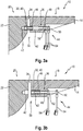
- the through bore 36 ( Fig. 2b ) is in the first assembly 18, in particular the oil pan 14 is formed. Through a cover 38, the through hole 36 is closed to prevent the ingress of dirt.
- the centering means 30 may, for example, have a rotationally symmetrical cross-section and be formed in the form of a sleeve or a cylindrical pin 40.
- the centering means 30 in the form of a cylindrical pin 40 bridges in the centering position 32 the gap 34 between the first and the second assembly 18, 20.
- the centering means 30 is in each case partially in a recess 42 of the first and second assembly 18, 20, in particular the oil pan 14 and the front frame 22.
- the recess 42 in the front frame 22 is formed in the form of a blind hole, in which the centering means 30 can be inserted, for example, during assembly of the chassis 10.
- the recess 42 in the oil pan is formed as a through hole 36, which has areas with different diameters.
- the recess 42 in the first assembly 18, in particular the oil pan 14, is designed such that the centering means 30 at least at one of the second assembly 20 facing the end is fully absorbable.
- the complete inclusion of the centering means 30 in an assembly 18, 20, 26 in an assembled state of the chassis 10 allows disassembly of individual components 12, 14, 16, 22 of an assembly 18, 20, 26 without the chassis 10 and / or assemblies 18th , 20, 26 have to be completely dismantled. As a result, for example, disassembly and repair or replacement of the oil pan 14 can take place without the first assembly 18 having to be completely separated from the chassis 10.
- connection profile 46 which is in the form of an internal thread.
- a connection profile 46 can also be arranged at the end on the centering means 30 in order to enable a non-positive and / or positive connection with a pulling device 44.
- the illustrated pulling device 44 is designed in the form of a screw 48, which is connected through the through-bore 36 with the connecting profile 46, that is to say the internal thread, of the centering means 30.
- the screw 48 has at its end a screw head 50, and on the thread of the screw 48, a nut 52 is movably arranged.
- the screw head 50 and the nut 52 can be actuated by tools 54, in particular wrench, or fixed in a rotationally fixed manner.
- the mother 50 in FIG. 3b can thereby be brought into abutment with the first assembly 18, in particular the oil pan 14 and while holding the screw head 52 non-rotatably, the screw 48 and thus the centering means 30 can be moved out of the through-bore 36.
- the centering means 30 is thereby until the complete inclusion in the recess 42 in the first assembly 18, in particular the oil pan 14, displaced and thus in a disassembly position 56 can be brought.
- oil pan 14 can be disassembled as a single component of the first assembly 18. It is particularly advantageous if, during a subsequent assembly of, for example, the oil pan 14, it is first aligned precisely with the other components 22 and / or assemblies 18, 20 prior to tightening the screw connections 28. This can be achieved by a displacement of the centering means 30 from the disassembly position 56 into the centering position 32, whereby the component 14 can be precisely aligned even after disassembly again.
- a centering means 30 may at least partially have a rotationally asymmetric cross section, for example, by a, at least partially, oval or polygonal cross section.
- This rotationally asymmetrical cross section can cooperate in a form-fitting manner with the recess 42 of an assembly 18, 20, 26 in order to prevent the centering means 30 from rotating.
- the centering means 30 may be formed in one piece or several pieces, and, for example, to generate a rotationally asymmetric cross-section circumferentially have a feather key, which can act positively with a correspondingly formed recess 42 together.
- An alternative pulling device 44 may be in the form of a so-called peeling tool, which is likewise connectable to the centering means 30 via a screw connection.
- a percussion handle is used, which is moved along the Abziehwerkmaschinees up to a stop, which can be pulled out by the impact of the percussion handle on the stop the Abziehwerkmaschine with the centering of a recess 42.
Description
- Die Erfindung betrifft eine landwirtschaftliche Arbeitsmaschine, insbesondere einen Traktor, mit einem Fahrgestell gemäß dem Oberbegriff des Anspruches 1, sowie ein Verfahren zur Demontage einer Baugruppe eines Fahrgestells gemäß Anspruch 7.
- Moderne landwirtschaftliche Arbeitsmaschinen wie Traktoren weisen üblicherweise ein Fahrgestell auf, welches zumindest zum Teil durch mehrere miteinander verbundene Baugruppen gebildet wird. Baugruppen können dabei beispielsweise ein Antriebsmotor oder ein Getriebe der Arbeitsmaschine sein. Derart miteinander verbundene Baugruppen bilden einen Teil des Fahrgestells und tragen wesentlich zu dessen Steifigkeit und Tragfähigkeit bei. Bekannt ist auch, eine Ölwanne, welche einen Teil der Baugruppe "Antriebsmotor" bilden kann, derart mit dem Antriebsmotor und zumindest einer angrenzenden Baugruppe zu verbinden, dass diese ebenfalls ein tragendes Bauteil des Fahrgestells der Arbeitsmaschine bildet. Verbindungsmittel zum Verbinden von Bauteilen sind aus der
NL7611626A DE102008021905A1 bekannt. - Eine derartig mit einem Antriebsmotor verbundene Ölwanne ist aus der
DE 699 29 394 T2 bekannt. Hierbei sind ein Motorblock und eine Ölwanne miteinander und mit einer Vorderradaufhängung verschraubt. Der Motor bildet dabei einen Teil des Fahrgestells des Traktors, wobei die Vorderradaufhängung eine vordere Fortsetzung des Fahrgestells bildet, an der unter anderem die Vorderräder und deren Lenkungsmechanismus befestig sind. Zum Ausgleich von Toleranzen in Längsrichtung des Traktors ist zwischen der Vorderradaufhängung und der Ölwanne ein Spalt vorgesehen, welcher durch den Einsatz von in der Vorderachsaufhängung angeordneten Hülsen überbrückt wird, um so bei der Montage einen Toleranzausgleich vornehmen zu können. Nachteilig ist hierbei, dass ein Toleranzausgleich zwischen den Bauteilen zwar in Längsrichtung vorgenommen werden kann, jedoch keine Ausrichtung der Bauteile zueinander in einer Richtung quer zu der Längsrichtung, wodurch beispielsweise eine genaue Ausrichtung einer Frontzapfwelle erschwert wird. Zudem wird durch den festen Einbau und die Anordnung der Hülsen eine Demontage einzelner Bauteile des Fahrgestells ohne Demontage des gesamten Fahrgestells unmöglich gemacht. - Es ist daher die Aufgabe der vorliegenden Erfindung, eine Vorrichtung und ein Verfahren bereitzustellen, welche eine verbesserte Montage und Wartung einer landwirtschaftlichen Arbeitsmaschine ermöglichen.
- Die Lösung der Aufgabe erfolgt erfindungsgemäß durch die kennzeichnenden Merkmale der Ansprüche 1 und 7. Vorteilhafte Ausgestaltungen der Erfindung sind in den Unteransprüchen angegeben.
- Eine landwirtschaftliche Arbeitsmaschine, insbesondere ein Traktor, umfasst ein Fahrgestell, welches mindestens eine erste Baugruppe und eine zweite Baugruppe aufweist, wobei eine Baugruppe jeweils mindestens ein Bauteil umfasst, und wobei das Fahrgestell mindestens ein Zentriermittel aufweist, welches in einem montierten Zustand des Fahrgestells in einer Zentrierposition zwischen zwei aneinander angeordneten, und insbesondere lösbar miteinander verbundenen, Baugruppen angeordnet ist, wobei in der Zentrierposition das Zentriermittel jeweils zumindest teilweise in den aneinander angeordneten Baugruppen in dafür ausgebildeten Aussparungen aufgenommen ist. Gemäß der Erfindung ist das Zentriermittel in dem montierten Zustand des Fahrgestells von der Zentrierposition in eine Demontageposition verbringbar, in welcher das Zentriermittel nur in einer der Baugruppen aufgenommen ist. Durch das Zentriermittel kann bei einer Montage des Fahrgestells eine präzisere Ausrichtung der Baugruppen, insbesondere quer zu einer Längsrichtung des Fahrgestells und/oder der Arbeitsmaschine, zueinander erfolgen. Das Verbringen des Zentriermittels in die Demontageposition bei montiertem Fahrgestell ermöglicht darüber hinaus eine Demontage einzelner Bauteile einer Baugruppe, beispielsweise der Ölwanne, ohne dass die zugeordnete Baugruppe oder das Fahrgestell vollständig demontiert werden müssen. Dies hat den Vorteil, dass neben einer verbesserten Montage durch präzisere Ausrichtung der Baugruppen zueinander auch eine einfachere Wartung einer landwirtschaftlichen Arbeitsmaschine gewährleistet werden kann.
- In einer bevorzugten Ausgestaltung der Erfindung ist eine Aussparung zur vollständigen Aufnahme des Zentriermittels in einer der Baugruppen als Durchgangsbohrung ausgebildet. Durch die Ausgestaltung der Aussparung zur vollständigen Aufnahme des Zentriermittels als Durchgangsbohrung durch ein Bauteil und/oder eine Baugruppe, kann zusammen mit dem Zugang zu dem Zentriermittel auch kostengünstig die Aussparung zur vollständigen Aufnahme des Zentriermittels gefertigt werden.
- In einer besonders bevorzugten Ausgestaltung der Erfindung weist das Zentriermittel radial innenseitig und/oder endseitig ein Verbindungsprofil auf, durch welches das Zentriermittel mit einer Ziehvorrichtung verbindbar ist. Das Verbindungsprofil des Zentriermittels ermöglicht eine, insbesondere kraftschlüssige und/oder formschlüssige, Verbindung des Zentriermittels mit einer Ziehvorrichtung. Dies bietet den Vorteil, dass das Zentriermittel axial in beide Richtungen verlagerbar ist, also beispielsweise nicht nur in eine Richtung geschlagen sondern auch mit der Ziehvorrichtung in die Demontageposition gezogen werden kann.
- In einer weiteren bevorzugten Ausgestaltung der Erfindung weist das Zentriermittel einen zumindest teilweise rotationssymmetrisch ausgebildeten Querschnitt auf, und ist insbesondere in Form einer Hülse oder eines Zylinderstiftes ausgebildet. Aufgrund der rotationssymmetrischen Form können sowohl das Zentriermittel als auch die Aussparungen kostengünstig hergestellt werden. Zudem bietet der Einsatz von beispielsweise standardisierten Hülsen oder Zylinderstiften die Möglichkeit Kosten weiter zu reduzieren.
- Vorteilhafterweise weist das Zentriermittel einen zumindest teilweise rotationsunsymmetrisch ausgebildeten Querschnitt auf. Entlang seiner Längserstreckung kann ein Zentriermittel zumindest abschnittsweise einen rotationsunsymmetrischen Querschnitt aufweisen. Dieser rotationsunsymmetrische Querschnitt kann mit einer entsprechend ausgebildeten Aussparung zusammenwirken, wodurch eine Rotation des Zentriermittels um eine Längsachse durch Formschluss mit der Aussparung, insbesondere bei einer Verlagerung, vermieden werden kann. Dies hat den Vorteil, dass eine Verlagerung des Zentriermittels auch mit einer einfachen Ziehvorrichtung erfolgen kann.
- In einer weiterhin bevorzugten Ausführungsform ist das Zentriermittel in einem montierten Zustand des Fahrgestells von der Demontageposition in die Zentrierposition verlagerbar. Durch eine Verlagerung des Zentriermittels in die Zentrierposition kann eine präzise Ausrichtung beispielsweise eines ausgebauten oder ausgetauschten Bauteils erfolgen, bevor dieses vollständig an den angrenzenden Baugruppen befestigt wird.
- Dies hat den Vorteil, dass auch nach einem Austausch oder einer Reparatur ein Bauteil so präzise wie bei der Erstmontage ausgerichtet werden kann, wodurch beispielsweise ein erhöhter Verschleiß aufgrund einer unpräzisen Ausrichtung vermieden werden kann.
- In einer weiteren vorteilhaften Ausgestaltung der Erfindung ist die Ziehvorrichtung in Form einer Gewindestange, einer Schraube oder in Form eines Abziehwerkzeuges, insbesondere mit einem Schlaggriff, ausgebildet. Eine einfache Ziehvorrichtung kann beispielsweise eine Schraube oder eine Gewindestange mit einer Mutter sein, welche form- und/oder kraftschlüssig mit dem Zentriermittel verbunden ist. Dies hat den Vorteil, dass ohne spezielle Werkzeuge eine Verlagerung des Zentriermittels erfolgen kann. Ein sogenanntes Abziehwerkzeug, insbesondere mit einem Schlaggriff, welches kraft- und/oder formschlüssig mit einem Zentriermittel verbunden werden kann, hat den Vorteil, dass eine Verlagerung des Zentriermittels ohne großen Zeitaufwand erfolgen kann.
- Weiterhin betrifft die Erfindung ein Verfahren zur Demontage einer Baugruppe oder eines Bauteils einer Baugruppe eines Fahrgestells einer landwirtschaftlichen Arbeitsmaschine, umfassend die Schritte Verbinden einer Ziehvorrichtung mit jeweils einem in einer Zentrierposition angeordneten Zentriermittel eines Fahrgestells einer landwirtschaftlichen Arbeitsmaschine; Verlagern des mindestens einen Zentriermittels von der Zentrierposition in eine Demontageposition; und Demontieren der Baugruppe und/oder des Bauteils der Baugruppe. Durch das Zentriermittel kann bei einer Montage des Fahrgestells eine präzisere Ausrichtung der Baugruppen, insbesondere quer zu einer Längsrichtung des Fahrgestells und/oder der Arbeitsmaschine, zueinander erfolgen. Das Verbringen des Zentriermittels in die Demontageposition bei montiertem Fahrgestell hat darüber hinaus den Vorteil, dass eine Demontage einzelner Bauteile einer Baugruppe, beispielsweise der Ölwanne, erfolgen kann, ohne dass die zugeordnete Baugruppe oder das Fahrgestell vollständig demontiert werden müssen.
- In einer vorteilhaften Weiterbildung des Verfahrens sind ein Verbinden einer Ziehvorrichtung mit jeweils einem in einer Demontageposition angeordneten Zentriermittel des montierten Fahrgestells und ein Verlagern des mindestens einen Zentriermittels von der Demontageposition in die Zentrierposition vorgesehen. Dies hat den Vorteil, dass auch nach einem Austausch oder einer Reparatur ein Bauteil so präzise wie bei der Erstmontage ausgerichtet werden kann.
- Nachfolgend wird die Erfindung unter Bezugnahme auf die anliegenden Zeichnungen näher erläutert.
- Es zeigt:
- Fig. 1:
- eine schematische Seitenansicht eines Fahrgestells einer landwirtschaftlichen Arbeitsmaschine;
- Fig. 2a,b:
- eine schematische Darstellung einer ersten Baugruppe und einer zweiten Baugruppe eines Fahrgestells;
- Fig. 3a:
- eine schematische Schnittansicht eines Zentriermittels in einer Zentrierposition; und
- Fig. 3b:
- eine schematische Schnittansicht eines Zentriermittels aus
Fig. 3a in einer Demontageposition. - In
Fig. 1 ist in einer Seitenansicht ein Fahrgestell 10 einer erfindungsgemäßen landwirtschaftlichen Arbeitsmaschine in Form eines Traktors dargestellt. Die Arbeitsmaschine weist einen Antriebsmotor 12 auf, welcher bodenseitig mit einer Ölwanne 14 und rückseitig mit einem Kupplungsgehäuse 16 verbunden ist. Der Antriebsmotor 12, die Ölwanne 14 und das Kupplungsgehäuse 16 bilden dabei eine erste Baugruppe 18 des Fahrgestells 10. Der Antriebsmotor 12, die Ölwanne 14 und das Kupplungsgehäuse 16 sind dabei Bauteile der ersten Baugruppe 18. Eine zweite Baugruppe 20 des Fahrgestells 10 wird durch eine Vorderachsbaugruppe gebildet, von der lediglich ein Frontrahmen 22 dargestellt ist, an dem beispielsweise eine Vorderachse der Arbeitsmaschine angeordnet sein kann. Rückseitig der ersten Baugruppe 18 ist ein Getriebeblock 24 angeordnet, welcher eine dritte Baugruppe 26 des Fahrgestells 10 bildet. Die Baugruppen 18, 20, 26 sind lösbar miteinander verbunden, beispielsweise durch Schraubverbindungen 28, und bilden einen tragenden Teil des Fahrgestells 10. Die zweite Baugruppe 20 ist dabei derart an der ersten Baugruppe 18 angeordnet, dass der Frontrahmen 22 mittels Schraubverbindungen 28 an dem Antriebsmotor 12 und der Ölwanne 14 befestigt ist. Zum präzisen Ausrichten der Baugruppen 18, 20, 26 zueinander bei der Montage ist zumindest ein Zentriermittel 30 vorgesehen. Das Zentriermittel 30 ist dabei zwischen der ersten Baugruppe 18 und der zweiten Baugruppe 20 in einer Zentrierposition 32 angeordnet, in der das Zentriermittel 30 jeweils in der ersten und zweiten Baugruppe 18, 20 teilweise angeordnet ist. Hierdurch kann eine präzise Ausrichtung der ersten und zweiten Baugruppe 18, 20, insbesondere quer zu einer Längsrichtung, bewirkt werden. - Gemäß der Erfindung ist das Zentriermittel 30 in einem montierten Zustand des Fahrgestells 10 von der Zentrierposition 32 in eine Demontageposition verbringbar, in welcher das Zentriermittel 30 nur in einer der Baugruppen 18, 20 aufgenommen ist. In
Figur 2a ist das Zentriermittel 30 in der Zentrierposition 32 benachbart zu einer Schraubverbindung 28 angeordnet dargestellt. Das Zentriermittel 30 kann dabei in der Zentrierposition 32 einen Spalt 34 überbrücken, welcher beispielsweise zum Ausgleich von Toleranzen in Längsrichtung zwischen dem ersten und zweiten Bauteil 18, 20 ausgebildet sein kann. Zur Verlagerung ist das Zentriermittel 30 über eine Durchgangsbohrung 36 zugänglich. Die Durchgangsbohrung 36 (Fig. 2b ) ist dabei in der ersten Baugruppe 18, insbesondere der Ölwanne 14, ausgebildet. Durch eine Abdeckung 38 ist die Durchgangsbohrung 36 verschließbar, um das Eindringen von Schmutz zu vermeiden. - Das Zentriermittel 30 (
Fig. 3a ) kann beispielsweise einen rotationssymmetrischen Querschnitt aufweisen und in Form einer Hülse oder eines Zylinderstiftes 40 ausgebildet sein. Das Zentriermittel 30 in Form eines Zylinderstiftes 40 überbrückt in der Zentrierposition 32 den Spalt 34 zwischen der ersten und der zweiten Baugruppe 18, 20. Gelagert ist das Zentriermittel 30 dabei jeweils teilweise in einer Aussparung 42 der ersten und zweiten Baugruppe 18, 20, insbesondere in der Ölwanne 14 und dem Frontrahmen 22. Die Aussparung 42 in dem Frontrahmen 22 ist dabei in Form eines Sackloches ausgebildet, in welches das Zentriermittel 30 beispielsweise bei der Montage des Fahrgestells 10 gesteckt werden kann. Die Aussparung 42 in der Ölwanne ist dabei als Durchgangsbohrung 36 ausgebildet, welche Bereiche mit unterschiedlichen Durchmessern aufweist. Die Aussparung 42 in der ersten Baugruppe 18, insbesondere der Ölwanne 14, ist dabei derart ausgebildet, dass das Zentriermittel 30 zumindest an einem der zweiten Baugruppe 20 zugewandten Ende vollständig aufnehmbar ist. Die vollständige Aufnahme des Zentriermittels 30 in einer Baugruppe 18, 20, 26 in einem montierten Zustand des Fahrgestells 10 ermöglicht eine Demontage einzelner Bauteile 12, 14, 16, 22 einer Baugruppe 18, 20, 26 ohne dass das Fahrgestell 10 und/oder Baugruppen 18, 20, 26 vollständig demontiert werden müssen. Hierdurch kann beispielsweise eine Demontage und eine Reparatur oder Austausch der Ölwanne 14 erfolgen, ohne dass die erste Baugruppe 18 vollständig von dem Fahrgestell 10 getrennt werden muss. - Durch die Durchgangsbohrung 36 hindurch kann das Zentriermittel 30 mit einer Ziehvorrichtung 44 verbunden werden. Hierfür weist das Zentriermittel 30 ein Verbindungsprofil 46 auf, welche in Form eines Innengewindes ausgebildet ist. Ein Verbindungsprofil 46 kann dabei auch endseitig an dem Zentriermittel 30 angeordnet sein, um eine kraft- und/oder formschlüssige Verbindung mit einer Ziehvorrichtung 44 zu ermöglichen. Die dargestellte Ziehvorrichtung 44 ist in Form einer Schraube 48 ausgebildet, welche durch die Durchgangsbohrung 36 mit dem Verbindungsprofil 46, also dem Innengewinde, des Zentriermittels 30 verbunden ist. Die Schraube 48 weist endseitig einen Schraubenkopf 50 auf, und auf dem Gewinde der Schraube 48 ist eine Mutter 52 beweglich angeordnet. Der Schraubenkopf 50 und die Mutter 52 können durch Werkzeug 54, insbesondere Schraubenschlüssel, betätigt oder drehfest fixiert werden.
- Die Mutter 50 in
Figur 3b kann dabei mit der ersten Baugruppe 18, insbesondere der Ölwanne 14, in Anlage gebracht werden und bei gleichzeitigem drehfesten halten des Schraubenkopfes 52 kann die Schraube 48 und damit das Zentriermittel 30 aus der Durchgangsbohrung 36 heraus bewegt werden. Das Zentriermittel 30 ist dadurch bis zur vollständigen Aufnahme in der Aussparung 42 in der ersten Baugruppe 18, insbesondere der Ölwanne 14, verlagerbar und somit in eine Demontageposition 56 verbringbar. Durch lösen der Schraubverbindungen 28 kann somit Ölwanne 14 als einzelnes Bauteil der ersten Baugruppe 18 demontiert werden. Besonders vorteilhaft ist es, wenn bei einer anschließenden Montage beispielsweise der Ölwanne 14 diese vor einem festziehen der Schraubverbindungen 28 zunächst präzises zu den anderen Bauteilen 22 und/oder Baugruppen 18, 20 ausgerichtet wird. Dies kann durch eine Verlagerung des Zentriermittels 30 von der Demontageposition 56 in die Zentrierposition 32 erfolgen, wodurch das Bauteil 14 auch nach einer Demontage wieder präzise ausgerichtet werden kann. - Ein Zentriermittel 30 kann zumindest teilweise einen rotationsunsymmetrischen Querschnitt aufweisen, beispielsweise durch einen, zumindest abschnittsweise, ovalen oder eckigen Querschnitt. Dieser rotationsunsymmetrische Querschnitt kann mit der Aussparung 42 einer Baugruppe 18, 20, 26 formschlüssig zusammenwirken, um ein Verdrehen des Zentriermittels 30 zu vermeiden. Dies hat den Vorteil, dass beispielsweise das zweite Werkzeug 54 zum fixieren des Schraubenkopfes 50 entfallen könnte. Das Zentriermittel 30 kann einstückig oder mehrstückig ausgebildet sein, und beispielsweise zur Erzeugung eines rotationsunsymmetrischen Querschnittes umfangsseitig eine Passfeder aufweise, welche mit einer entsprechend ausgebildeten Aussparung 42 formschlüssig zusammen wirken kann. Eine alternative Ziehvorrichtung 44 kann in Form eines sogenannten Abziehwerkzeuges ausgebildet sein, welches ebenfalls über eine Schraubverbindung mit dem Zentriermittel 30 verbindbar ist. Zum Ziehen des Zentriermittels 30 wird jedoch ein Schlaggriff verwendet, welcher entlang des Abziehwerkzeuges bis zu einem Anschlag bewegt wird, wobei durch den Aufprall des Schlaggriffes auf den Anschlag das Abziehwerkzeug mit dem Zentriermittel aus einer Aussparung 42 herausgezogen werden kann.
-
- 10
- Fahrgestell
- 12
- Antriebsmotor
- 14
- Ölwanne
- 16
- Kupplungsgehäuse
- 18
- erste Baugruppe
- 20
- zweite Baugruppe
- 22
- Frontrahmen
- 24
- Getriebeblock
- 26
- dritte Baugruppe
- 28
- Schraubverbindung
- 30
- Zentriermittel
- 32
- Zentrierposition
- 34
- Spalt
- 36
- Durchgangsbohrung
- 38
- Abdeckung
- 40
- Zylinderstift
- 42
- Aussparung
- 44
- Ziehvorrichtung
- 46
- Verbindungsprofil
- 48
- Schraube
- 50
- Schraubenkopf
- 52
- Mutter
- 54
- Werkzeug
- 56
- Demontageposition
Claims (7)
- Landwirtschaftliche Arbeitsmaschine, insbesondere Traktor, mit einem Fahrgestell (10), welches mindestens eine erste Baugruppe (18) und eine zweite Baugruppe (20) aufweist, wobei eine Baugruppe (18, 20, 26) jeweils mindestens ein Bauteil (12, 14, 16, 22, 24) umfasst, und wobei das Fahrgestell (10) mindestens ein Zentriermittel (30) aufweist, welches in einem montierten Zustand des Fahrgestells (10) in einer Zentrierposition (32) zwischen zwei aneinander angeordneten Baugruppen (18, 20, 26) angeordnet ist, wobei in der Zentrierposition (32) das Zentriermittel (30) jeweils zumindest teilweise in den aneinander angeordneten Baugruppen (18, 20, 26) in dafür ausgebildeten Aussparungen (42) aufgenommen ist, dadurch gekennzeichnet, dass das Zentriermittel (30) in dem montierten Zustand des Fahrgestells (10) von der Zentrierposition (32) in eine Demontageposition (56) verbringbar ist, in welcher das Zentriermittel (30) nur in einer der Baugruppen (18, 20, 26) aufgenommen ist, wobei das Zentriermittel (30) radial innenseitig und/oder endseitig ein Verbindungsprofil (46) aufweist, durch welches das Zentriermittel (30) mit einer Ziehvorrichtung (44) verbindbar ist.
- Arbeitsmaschine nach Anspruch 1, dadurch gekennzeichnet, dass eine Aussparung (42) zur vollständigen Aufnahme des Zentriermittels (30) in einer der Baugruppen (18, 20, 26) als Durchgangsbohrung (36) ausgebildet ist.
- Arbeitsmaschine nach Anspruch 1 oder 2, dadurch gekennzeichnet, dass das Zentriermittel (30) einen zumindest teilweise rotationssymmetrisch ausgebildeten Querschnitt aufweist, und insbesondere in Form einer Hülse oder eines Zylinderstiftes (40) ausgebildet ist.
- Arbeitsmaschine nach einem der vorherigen Ansprüche, dadurch gekennzeichnet, dass das Zentriermittel (30) einen zumindest teilweise rotationsunsymmetrisch ausgebildeten Querschnitt aufweist.
- Arbeitsmaschine nach einem der vorherigen Ansprüche, dadurch gekennzeichnet, dass das Zentriermittel (30) in einem montierten Zustand des Fahrgestells (10) von der Demontageposition (56) in die Zentrierposition (32) verlagerbar ist.
- Arbeitsmaschine nach einem der vorherigen Ansprüche, dadurch gekennzeichnet, dass die Ziehvorrichtung (44) in Form einer Gewindestange, einer Schraube (48) oder in Form eines Abziehwerkzeuges, insbesondere mit einem Schlaggriff, ausgebildet ist.
- Verfahren zur Demontage einer Baugruppe oder eines Bauteils einer Baugruppe eines Fahrgestells (10) einer landwirtschaftlichen Arbeitsmaschine, insbesondere nach einem der Ansprüche 1 bis 6, umfassend die Schritte- Verbinden einer Ziehvorrichtung (44) mit jeweils einem in einer Zentrierposition (32) angeordneten Zentriermittel (30) eines Fahrgestells (30) einer landwirtschaftlichen Arbeitsmaschine;- Verlagern des mindestens einen Zentriermittels (30) von der Zentrierposition (32) in eine Demontageposition (56);- Demontieren der Baugruppe (18, 20, 26) und/oder eines Bauteils (12, 14, 16, 22) der Baugruppe (18, 20, 26).- Verbinden einer Ziehvorrichtung (44) mit jeweils einem in einer Demontageposition (56) angeordneten Zentriermittel (30) des montierten Fahrgestells (10);- Verlagern des mindestens einen Zentriermittels (30) von der Demontageposition (56) in die Zentrierposition (32).
Applications Claiming Priority (1)
| Application Number | Priority Date | Filing Date | Title |
|---|---|---|---|
| DE102016117000.3A DE102016117000A1 (de) | 2016-09-09 | 2016-09-09 | Landwirtschaftliche Arbeitsmaschine |
Publications (2)
| Publication Number | Publication Date |
|---|---|
| EP3293080A1 EP3293080A1 (de) | 2018-03-14 |
| EP3293080B1 true EP3293080B1 (de) | 2019-09-25 |
Family
ID=58638713
Family Applications (1)
| Application Number | Title | Priority Date | Filing Date |
|---|---|---|---|
| EP17168177.8A Active EP3293080B1 (de) | 2016-09-09 | 2017-04-26 | Landwirtschaftliche arbeitsmaschine |
Country Status (2)
| Country | Link |
|---|---|
| EP (1) | EP3293080B1 (de) |
| DE (1) | DE102016117000A1 (de) |
Family Cites Families (5)
| Publication number | Priority date | Publication date | Assignee | Title |
|---|---|---|---|---|
| FR2328869A1 (fr) * | 1975-10-22 | 1977-05-20 | Stein Industrie | Dispositif d'assemblage de deux brides planes de flexibilites differentes ou non |
| GB9824341D0 (en) | 1998-11-07 | 1998-12-30 | New Holland Uk Ltd | Securing spaced elements to one other |
| DE102008021905A1 (de) * | 2007-05-25 | 2008-11-27 | Heidelberger Druckmaschinen Ag | Zentrierbuchse |
| US20130322985A1 (en) * | 2012-05-31 | 2013-12-05 | United Technologies Corporation | Retention assembly including sleeve |
| FR2995372A1 (fr) * | 2012-09-13 | 2014-03-14 | Lisi Aerospace | Dispositif de fixation |
-
2016
- 2016-09-09 DE DE102016117000.3A patent/DE102016117000A1/de not_active Withdrawn
-
2017
- 2017-04-26 EP EP17168177.8A patent/EP3293080B1/de active Active
Non-Patent Citations (1)
| Title |
|---|
| None * |
Also Published As
| Publication number | Publication date |
|---|---|
| DE102016117000A1 (de) | 2018-03-15 |
| EP3293080A1 (de) | 2018-03-14 |
Similar Documents
| Publication | Publication Date | Title |
|---|---|---|
| EP1936109B1 (de) | Drehantriebsanordnung für ein Bohrgestänge | |
| EP2008774B1 (de) | Vorrichtung zum Ausziehen einer Einspritzdüse | |
| EP1690700B1 (de) | Vorrichtung zur variablen Demontage und Montage von Achsbauteilen | |
| DE3135689C2 (de) | Kupplung zum lösbaren Verbinden einer unterteilten Antriebswelle eines Kraftfahrzeuges | |
| EP3156666A1 (de) | Befestigungssystem für ein maschinenelement | |
| DE102010017592B4 (de) | Verfahren und Vorrichtung zur spanlosen axial umformenden Ausbildung einer Verzahnung mit angeformten Spitzen an einem Werkstück | |
| EP3293080B1 (de) | Landwirtschaftliche arbeitsmaschine | |
| DE102012012293B4 (de) | Vorrichtung zum Umformen eines Werkstücks | |
| DE102007011617A1 (de) | Verfahren zur Befestigung einer Gewindebuchse in einer Platte sowie das Werkzeug hierzu | |
| DE102010039980A1 (de) | Zentriervorrichtung für eine Kraftstoffeinspritzdüse | |
| EP3275597A1 (de) | Werkzeug und verfahren zum ein- und ausziehen von bauteilen | |
| EP3611404B1 (de) | Kettenzahnrad | |
| DE102005011843B4 (de) | Verfahren zum Bruchtrennen und Crackeinheit | |
| DE20316274U1 (de) | Vorrichtung zur Montage einer Ölspritzdüse | |
| DE102009052141A1 (de) | Manipulator für Schmiedemaschinen | |
| EP2505838B1 (de) | Kolbenverdichter | |
| EP0567750B1 (de) | Bodenbearbeitungsmaschine, insbesondere Kreiselegge | |
| DE202018101550U1 (de) | Stellhebel für ein Motorgerät | |
| EP1452758B1 (de) | Wellenflanschverbindung und Verfahren zum Herstellen einer derartigen Wellenflanschverbindung | |
| DE19611526C1 (de) | Vorrichtung zur gelenkigen Verbindung | |
| DE102016219823B3 (de) | Schneckenmaschine-Getriebe-Anordnung und Verfahren zur Wartung von Schneckenwellen einer derartigen Schneckenmaschine-Getriebe-Anordnung | |
| DE102008058384A1 (de) | Zahnradanordnung | |
| EP1555072B1 (de) | Axialgewinderollkopf | |
| DE102008027494A1 (de) | Mehrteilige Walze | |
| DE102014223082A1 (de) | Getriebegehäuse mit abnehmbarem Nebengehäuseteil zur erleichterten Gummilagermontage |
Legal Events
| Date | Code | Title | Description |
|---|---|---|---|
| PUAI | Public reference made under article 153(3) epc to a published international application that has entered the european phase |
Free format text: ORIGINAL CODE: 0009012 |
|
| STAA | Information on the status of an ep patent application or granted ep patent |
Free format text: STATUS: THE APPLICATION HAS BEEN PUBLISHED |
|
| AK | Designated contracting states |
Kind code of ref document: A1 Designated state(s): AL AT BE BG CH CY CZ DE DK EE ES FI FR GB GR HR HU IE IS IT LI LT LU LV MC MK MT NL NO PL PT RO RS SE SI SK SM TR |
|
| AX | Request for extension of the european patent |
Extension state: BA ME |
|
| STAA | Information on the status of an ep patent application or granted ep patent |
Free format text: STATUS: REQUEST FOR EXAMINATION WAS MADE |
|
| 17P | Request for examination filed |
Effective date: 20180914 |
|
| RBV | Designated contracting states (corrected) |
Designated state(s): AL AT BE BG CH CY CZ DE DK EE ES FI FR GB GR HR HU IE IS IT LI LT LU LV MC MK MT NL NO PL PT RO RS SE SI SK SM TR |
|
| GRAP | Despatch of communication of intention to grant a patent |
Free format text: ORIGINAL CODE: EPIDOSNIGR1 |
|
| STAA | Information on the status of an ep patent application or granted ep patent |
Free format text: STATUS: GRANT OF PATENT IS INTENDED |
|
| INTG | Intention to grant announced |
Effective date: 20190627 |
|
| GRAS | Grant fee paid |
Free format text: ORIGINAL CODE: EPIDOSNIGR3 |
|
| GRAA | (expected) grant |
Free format text: ORIGINAL CODE: 0009210 |
|
| STAA | Information on the status of an ep patent application or granted ep patent |
Free format text: STATUS: THE PATENT HAS BEEN GRANTED |
|
| AK | Designated contracting states |
Kind code of ref document: B1 Designated state(s): AL AT BE BG CH CY CZ DE DK EE ES FI FR GB GR HR HU IE IS IT LI LT LU LV MC MK MT NL NO PL PT RO RS SE SI SK SM TR |
|
| REG | Reference to a national code |
Ref country code: GB Ref legal event code: FG4D Free format text: NOT ENGLISH |
|
| REG | Reference to a national code |
Ref country code: CH Ref legal event code: EP |
|
| REG | Reference to a national code |
Ref country code: AT Ref legal event code: REF Ref document number: 1183560 Country of ref document: AT Kind code of ref document: T Effective date: 20191015 |
|
| REG | Reference to a national code |
Ref country code: IE Ref legal event code: FG4D Free format text: LANGUAGE OF EP DOCUMENT: GERMAN |
|
| REG | Reference to a national code |
Ref country code: DE Ref legal event code: R096 Ref document number: 502017002373 Country of ref document: DE |
|
| REG | Reference to a national code |
Ref country code: NL Ref legal event code: MP Effective date: 20190925 |
|
| PG25 | Lapsed in a contracting state [announced via postgrant information from national office to epo] |
Ref country code: HR Free format text: LAPSE BECAUSE OF FAILURE TO SUBMIT A TRANSLATION OF THE DESCRIPTION OR TO PAY THE FEE WITHIN THE PRESCRIBED TIME-LIMIT Effective date: 20190925 Ref country code: LT Free format text: LAPSE BECAUSE OF FAILURE TO SUBMIT A TRANSLATION OF THE DESCRIPTION OR TO PAY THE FEE WITHIN THE PRESCRIBED TIME-LIMIT Effective date: 20190925 Ref country code: SE Free format text: LAPSE BECAUSE OF FAILURE TO SUBMIT A TRANSLATION OF THE DESCRIPTION OR TO PAY THE FEE WITHIN THE PRESCRIBED TIME-LIMIT Effective date: 20190925 Ref country code: BG Free format text: LAPSE BECAUSE OF FAILURE TO SUBMIT A TRANSLATION OF THE DESCRIPTION OR TO PAY THE FEE WITHIN THE PRESCRIBED TIME-LIMIT Effective date: 20191225 Ref country code: NO Free format text: LAPSE BECAUSE OF FAILURE TO SUBMIT A TRANSLATION OF THE DESCRIPTION OR TO PAY THE FEE WITHIN THE PRESCRIBED TIME-LIMIT Effective date: 20191225 Ref country code: FI Free format text: LAPSE BECAUSE OF FAILURE TO SUBMIT A TRANSLATION OF THE DESCRIPTION OR TO PAY THE FEE WITHIN THE PRESCRIBED TIME-LIMIT Effective date: 20190925 |
|
| REG | Reference to a national code |
Ref country code: LT Ref legal event code: MG4D |
|
| PG25 | Lapsed in a contracting state [announced via postgrant information from national office to epo] |
Ref country code: RS Free format text: LAPSE BECAUSE OF FAILURE TO SUBMIT A TRANSLATION OF THE DESCRIPTION OR TO PAY THE FEE WITHIN THE PRESCRIBED TIME-LIMIT Effective date: 20190925 Ref country code: GR Free format text: LAPSE BECAUSE OF FAILURE TO SUBMIT A TRANSLATION OF THE DESCRIPTION OR TO PAY THE FEE WITHIN THE PRESCRIBED TIME-LIMIT Effective date: 20191226 Ref country code: LV Free format text: LAPSE BECAUSE OF FAILURE TO SUBMIT A TRANSLATION OF THE DESCRIPTION OR TO PAY THE FEE WITHIN THE PRESCRIBED TIME-LIMIT Effective date: 20190925 |
|
| PG25 | Lapsed in a contracting state [announced via postgrant information from national office to epo] |
Ref country code: ES Free format text: LAPSE BECAUSE OF FAILURE TO SUBMIT A TRANSLATION OF THE DESCRIPTION OR TO PAY THE FEE WITHIN THE PRESCRIBED TIME-LIMIT Effective date: 20190925 Ref country code: NL Free format text: LAPSE BECAUSE OF FAILURE TO SUBMIT A TRANSLATION OF THE DESCRIPTION OR TO PAY THE FEE WITHIN THE PRESCRIBED TIME-LIMIT Effective date: 20190925 Ref country code: EE Free format text: LAPSE BECAUSE OF FAILURE TO SUBMIT A TRANSLATION OF THE DESCRIPTION OR TO PAY THE FEE WITHIN THE PRESCRIBED TIME-LIMIT Effective date: 20190925 Ref country code: IT Free format text: LAPSE BECAUSE OF FAILURE TO SUBMIT A TRANSLATION OF THE DESCRIPTION OR TO PAY THE FEE WITHIN THE PRESCRIBED TIME-LIMIT Effective date: 20190925 Ref country code: RO Free format text: LAPSE BECAUSE OF FAILURE TO SUBMIT A TRANSLATION OF THE DESCRIPTION OR TO PAY THE FEE WITHIN THE PRESCRIBED TIME-LIMIT Effective date: 20190925 Ref country code: PT Free format text: LAPSE BECAUSE OF FAILURE TO SUBMIT A TRANSLATION OF THE DESCRIPTION OR TO PAY THE FEE WITHIN THE PRESCRIBED TIME-LIMIT Effective date: 20200127 Ref country code: PL Free format text: LAPSE BECAUSE OF FAILURE TO SUBMIT A TRANSLATION OF THE DESCRIPTION OR TO PAY THE FEE WITHIN THE PRESCRIBED TIME-LIMIT Effective date: 20190925 Ref country code: AL Free format text: LAPSE BECAUSE OF FAILURE TO SUBMIT A TRANSLATION OF THE DESCRIPTION OR TO PAY THE FEE WITHIN THE PRESCRIBED TIME-LIMIT Effective date: 20190925 |
|
| PG25 | Lapsed in a contracting state [announced via postgrant information from national office to epo] |
Ref country code: SM Free format text: LAPSE BECAUSE OF FAILURE TO SUBMIT A TRANSLATION OF THE DESCRIPTION OR TO PAY THE FEE WITHIN THE PRESCRIBED TIME-LIMIT Effective date: 20190925 Ref country code: SK Free format text: LAPSE BECAUSE OF FAILURE TO SUBMIT A TRANSLATION OF THE DESCRIPTION OR TO PAY THE FEE WITHIN THE PRESCRIBED TIME-LIMIT Effective date: 20190925 Ref country code: IS Free format text: LAPSE BECAUSE OF FAILURE TO SUBMIT A TRANSLATION OF THE DESCRIPTION OR TO PAY THE FEE WITHIN THE PRESCRIBED TIME-LIMIT Effective date: 20200224 Ref country code: CZ Free format text: LAPSE BECAUSE OF FAILURE TO SUBMIT A TRANSLATION OF THE DESCRIPTION OR TO PAY THE FEE WITHIN THE PRESCRIBED TIME-LIMIT Effective date: 20190925 |
|
| REG | Reference to a national code |
Ref country code: DE Ref legal event code: R097 Ref document number: 502017002373 Country of ref document: DE |
|
| PG2D | Information on lapse in contracting state deleted |
Ref country code: IS |
|
| PG25 | Lapsed in a contracting state [announced via postgrant information from national office to epo] |
Ref country code: DK Free format text: LAPSE BECAUSE OF FAILURE TO SUBMIT A TRANSLATION OF THE DESCRIPTION OR TO PAY THE FEE WITHIN THE PRESCRIBED TIME-LIMIT Effective date: 20190925 Ref country code: IS Free format text: LAPSE BECAUSE OF FAILURE TO SUBMIT A TRANSLATION OF THE DESCRIPTION OR TO PAY THE FEE WITHIN THE PRESCRIBED TIME-LIMIT Effective date: 20200126 |
|
| PLBE | No opposition filed within time limit |
Free format text: ORIGINAL CODE: 0009261 |
|
| STAA | Information on the status of an ep patent application or granted ep patent |
Free format text: STATUS: NO OPPOSITION FILED WITHIN TIME LIMIT |
|
| 26N | No opposition filed |
Effective date: 20200626 |
|
| PG25 | Lapsed in a contracting state [announced via postgrant information from national office to epo] |
Ref country code: MC Free format text: LAPSE BECAUSE OF FAILURE TO SUBMIT A TRANSLATION OF THE DESCRIPTION OR TO PAY THE FEE WITHIN THE PRESCRIBED TIME-LIMIT Effective date: 20190925 Ref country code: SI Free format text: LAPSE BECAUSE OF FAILURE TO SUBMIT A TRANSLATION OF THE DESCRIPTION OR TO PAY THE FEE WITHIN THE PRESCRIBED TIME-LIMIT Effective date: 20190925 |
|
| REG | Reference to a national code |
Ref country code: CH Ref legal event code: PL |
|
| PG25 | Lapsed in a contracting state [announced via postgrant information from national office to epo] |
Ref country code: LU Free format text: LAPSE BECAUSE OF NON-PAYMENT OF DUE FEES Effective date: 20200426 Ref country code: CH Free format text: LAPSE BECAUSE OF NON-PAYMENT OF DUE FEES Effective date: 20200430 Ref country code: LI Free format text: LAPSE BECAUSE OF NON-PAYMENT OF DUE FEES Effective date: 20200430 |
|
| REG | Reference to a national code |
Ref country code: BE Ref legal event code: MM Effective date: 20200430 |
|
| PG25 | Lapsed in a contracting state [announced via postgrant information from national office to epo] |
Ref country code: BE Free format text: LAPSE BECAUSE OF NON-PAYMENT OF DUE FEES Effective date: 20200430 |
|
| PG25 | Lapsed in a contracting state [announced via postgrant information from national office to epo] |
Ref country code: IE Free format text: LAPSE BECAUSE OF NON-PAYMENT OF DUE FEES Effective date: 20200426 |
|
| GBPC | Gb: european patent ceased through non-payment of renewal fee |
Effective date: 20210426 |
|
| PG25 | Lapsed in a contracting state [announced via postgrant information from national office to epo] |
Ref country code: GB Free format text: LAPSE BECAUSE OF NON-PAYMENT OF DUE FEES Effective date: 20210426 |
|
| PG25 | Lapsed in a contracting state [announced via postgrant information from national office to epo] |
Ref country code: TR Free format text: LAPSE BECAUSE OF FAILURE TO SUBMIT A TRANSLATION OF THE DESCRIPTION OR TO PAY THE FEE WITHIN THE PRESCRIBED TIME-LIMIT Effective date: 20190925 Ref country code: MT Free format text: LAPSE BECAUSE OF FAILURE TO SUBMIT A TRANSLATION OF THE DESCRIPTION OR TO PAY THE FEE WITHIN THE PRESCRIBED TIME-LIMIT Effective date: 20190925 Ref country code: CY Free format text: LAPSE BECAUSE OF FAILURE TO SUBMIT A TRANSLATION OF THE DESCRIPTION OR TO PAY THE FEE WITHIN THE PRESCRIBED TIME-LIMIT Effective date: 20190925 |
|
| PG25 | Lapsed in a contracting state [announced via postgrant information from national office to epo] |
Ref country code: MK Free format text: LAPSE BECAUSE OF FAILURE TO SUBMIT A TRANSLATION OF THE DESCRIPTION OR TO PAY THE FEE WITHIN THE PRESCRIBED TIME-LIMIT Effective date: 20190925 |
|
| REG | Reference to a national code |
Ref country code: AT Ref legal event code: MM01 Ref document number: 1183560 Country of ref document: AT Kind code of ref document: T Effective date: 20220426 |
|
| P01 | Opt-out of the competence of the unified patent court (upc) registered |
Effective date: 20230516 |
|
| PG25 | Lapsed in a contracting state [announced via postgrant information from national office to epo] |
Ref country code: AT Free format text: LAPSE BECAUSE OF NON-PAYMENT OF DUE FEES Effective date: 20220426 |
|
| PGFP | Annual fee paid to national office [announced via postgrant information from national office to epo] |
Ref country code: FR Payment date: 20230424 Year of fee payment: 7 Ref country code: DE Payment date: 20230420 Year of fee payment: 7 |