EP3292958B1 - Ausziehverfahren für eine sicherungsschraube und auszieher zur anwendung des verfahrens - Google Patents
Ausziehverfahren für eine sicherungsschraube und auszieher zur anwendung des verfahrens Download PDFInfo
- Publication number
- EP3292958B1 EP3292958B1 EP16315008.9A EP16315008A EP3292958B1 EP 3292958 B1 EP3292958 B1 EP 3292958B1 EP 16315008 A EP16315008 A EP 16315008A EP 3292958 B1 EP3292958 B1 EP 3292958B1
- Authority
- EP
- European Patent Office
- Prior art keywords
- extractor
- screw
- head
- rod
- drill
- Prior art date
- Legal status (The legal status is an assumption and is not a legal conclusion. Google has not performed a legal analysis and makes no representation as to the accuracy of the status listed.)
- Active
Links
- 238000000034 method Methods 0.000 title claims description 27
- 238000005553 drilling Methods 0.000 claims description 18
- 238000000605 extraction Methods 0.000 claims description 16
- 238000009527 percussion Methods 0.000 claims description 13
- 229930040373 Paraformaldehyde Natural products 0.000 claims description 7
- 229920006324 polyoxymethylene Polymers 0.000 claims description 7
- UONOETXJSWQNOL-UHFFFAOYSA-N tungsten carbide Chemical compound [W+]#[C-] UONOETXJSWQNOL-UHFFFAOYSA-N 0.000 claims description 6
- -1 polyoxymethylene Polymers 0.000 claims description 4
- KWGRBVOPPLSCSI-WPRPVWTQSA-N (-)-ephedrine Chemical compound CN[C@@H](C)[C@H](O)C1=CC=CC=C1 KWGRBVOPPLSCSI-WPRPVWTQSA-N 0.000 description 7
- 208000031968 Cadaver Diseases 0.000 description 4
- 229910000831 Steel Inorganic materials 0.000 description 3
- 238000003780 insertion Methods 0.000 description 3
- 230000037431 insertion Effects 0.000 description 3
- 239000010959 steel Substances 0.000 description 3
- 230000008901 benefit Effects 0.000 description 2
- 235000020303 café frappé Nutrition 0.000 description 2
- 230000014759 maintenance of location Effects 0.000 description 2
- 239000000463 material Substances 0.000 description 2
- 239000003973 paint Substances 0.000 description 2
- 230000000717 retained effect Effects 0.000 description 2
- 239000002966 varnish Substances 0.000 description 2
- 229910000760 Hardened steel Inorganic materials 0.000 description 1
- 238000010009 beating Methods 0.000 description 1
- 230000007423 decrease Effects 0.000 description 1
- 229940082150 encore Drugs 0.000 description 1
- 239000007769 metal material Substances 0.000 description 1
- 238000000926 separation method Methods 0.000 description 1
Images

Classifications
-
- B—PERFORMING OPERATIONS; TRANSPORTING
- B25—HAND TOOLS; PORTABLE POWER-DRIVEN TOOLS; MANIPULATORS
- B25B—TOOLS OR BENCH DEVICES NOT OTHERWISE PROVIDED FOR, FOR FASTENING, CONNECTING, DISENGAGING OR HOLDING
- B25B27/00—Hand tools, specially adapted for fitting together or separating parts or objects whether or not involving some deformation, not otherwise provided for
- B25B27/14—Hand tools, specially adapted for fitting together or separating parts or objects whether or not involving some deformation, not otherwise provided for for assembling objects other than by press fit or detaching same
- B25B27/18—Hand tools, specially adapted for fitting together or separating parts or objects whether or not involving some deformation, not otherwise provided for for assembling objects other than by press fit or detaching same withdrawing broken threaded parts or twist drills
-
- B—PERFORMING OPERATIONS; TRANSPORTING
- B25—HAND TOOLS; PORTABLE POWER-DRIVEN TOOLS; MANIPULATORS
- B25B—TOOLS OR BENCH DEVICES NOT OTHERWISE PROVIDED FOR, FOR FASTENING, CONNECTING, DISENGAGING OR HOLDING
- B25B23/00—Details of, or accessories for, spanners, wrenches, screwdrivers
- B25B23/02—Arrangements for handling screws or nuts
- B25B23/08—Arrangements for handling screws or nuts for holding or positioning screw or nut prior to or during its rotation
- B25B23/10—Arrangements for handling screws or nuts for holding or positioning screw or nut prior to or during its rotation using mechanical gripping means
- B25B23/105—Arrangements for handling screws or nuts for holding or positioning screw or nut prior to or during its rotation using mechanical gripping means the gripping device being an integral part of the driving bit
- B25B23/108—Arrangements for handling screws or nuts for holding or positioning screw or nut prior to or during its rotation using mechanical gripping means the gripping device being an integral part of the driving bit the driving bit being a Philips type bit, an Allen type bit or a socket
Definitions
- the invention lies in the field of processes and tooling for automobile mechanics and concerns in particular the methods and tools for dismounting vehicle wheels, for example motor vehicles.
- This specific tool is usually present in the vehicle. However, it may happen that this tool is lost or damaged preventing the user of the vehicle to change his wheel in case of puncture. The user must then call a professional mechanic who will either have the appropriate tool, or will have to find a solution to remove the security screw. It may also happen that the specific imprint shown by the screw head is damaged and therefore unusable, or that the tool has broken on the screw head and remains partly fixed on the latter so that the specific imprint is no longer accessible.
- the object of the invention is to meet at least one of the disadvantages presented by the prior art by proposing a method and tools for disassembling vehicle wheels that have a universal character in that they are likely to be used. on safety screws of different models or which are broken.
- step (b) of fitting comprises the use of a striking mandrel disposed between the extractor and the percussion tool and one end of which has a shape imprint conjugated to that of the head of the extractor.
- the invention consists in substituting the security screw head or broken, the head of an extractor that can be manipulated by standard tools. To do this, the invention will couple in rotation the extractor with the screw to be loosened by forcing it into a bore in said screw.
- the presence of the head and possibly a sleeve on the extractor forming a shoulder limits the depression of the extractor in the screw by abutment of the head of the screw on the head of the extractor or on the shoulder formed by the sleeve. This limitation of the depression of the rod of the extractor makes it possible to confine the rod of the extractor inside the screw and not to risk coming to hook the hub of the wheel while allowing the fitting of a rod of significant length in said screw.
- the use of a typing mandrel makes it possible to hold the extractor in position for its fitting.
- the tool set may also include an extraction mandrel for unhooking the extractor of the screw into which it is fitted.
- the extractor comprises a sleeve disposed at the base of the head, the sleeve having a diameter greater than that of the stem and less than that of the head so as to form a shoulder with the rod.
- the head of the extractor is hexagonal. More preferably, the extractor is steel.
- the extractor according to the invention is remarkable in that it makes it possible to have a straight fitting having a large contact surface with the screw to be loosened, making it possible to apply a loosening torque of up to 160 Nm or more for loosening the screw.
- the fitting of the extractor until the abutment of the head or the shoulder presented by the sleeve makes it possible firstly to be able to control the length of insertion of the rod and to constrain it not to exceed of the screw rod.
- the abutment avoids the beats during the manipulation of the extractor which would affect its retention in the screw, the head or the sleeve being placed in abutment against the screw.
- the invention relates to the use of an assembly as defined above for the extraction of a safety screw or a broken screw on a vehicle wheel.
- understand is synonymous with “include” and is not limiting in that it allows the presence of other elements in the device or the vehicle to which it refers. It is understood that the term “understand” includes the words “consist of”.
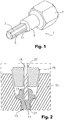
- the extractor 1 used for the implementation of the method of extracting a screw such as a safety screw or a broken screw.
- the extractor 1 according to the invention comprises a toothed rod 3 whose teeth, in the form of protruding ribs, extend longitudinally along the length of the rod 3, so that a cross section of the rod shows a configuration of star.
- the extractor 1 also has a head 7 which is preferably hexagonal in shape so that it can be handled by the standard keys.
- the extractor 1 is advantageously made of steel.
- the head 7 and the rod 3 are fixed to each other irreversibly so that during the insertion of the rod 3 into the screw the head can serve as a stop to limit the depression of the extractor and support to avoid beatings during manipulations as we will see later.
- the extractor 1 comprises a sleeve 9 disposed at the base of the head 7 and having a diameter greater than that of the rod 3 and less than that of the head 7 so as to form a shoulder 11 with the rod 3.
- the method according to the invention comprises the steps according to claim 1.
- the step a) of drilling a bore is represented on the figure 2 in the context of the extraction of a security screw 13 called "reentrant" in that it is disposed at the bottom of a cavity presented by the rim 15 of the wheel.
- This step therefore comprises drilling a bore 17 in the screw 13 to be loosened in the longitudinal direction thereof by means of a drill 19 of diameter less than the diameter of the rod 21 of the screw 13.
- the security screw is shown with a round head 23. The drilling operation is in progress so that the bore has not yet reached the screw shank. Nevertheless, in the process according to the invention, the screw shank is hollowed along all or part of its length.
- the length of the bore made in the screw is greater than 10 mm for example between 10 and 20 mm depending on the screw models considered.
- This length of the bore will allow to receive an extractor whose rod has a corresponding length and which therefore provides a large contact surface. This large contact surface will allow the application of sufficient torque for the loosening of the screw.
- the drilling is carried out by means of a drill 19.
- the step (a) of drilling the bore is done by means of a drill comprising a tungsten carbide tip.
- a drill comprising a tungsten carbide tip.
- Such a drill can for example be obtained by slitting the tip of a traditional steel drill bit to insert a tungsten carbide insert. The use of such a drill makes it easier to drill safety screws when they are made of a hardened steel.
- the diameter of the drill is equal to the diameter of the rod of the extractor so that the rod of the extractor can be engaged and be retained in the bore dug in the screw. It will be understood that the bore 17 must be central relative to the head 23 of the screw since it then extends into the rod 21 of this screw. Also according to a preferred embodiment of the invention, and as represented on the figure 2 , the step (a) of drilling the bore is performed using a centralizer 25 for positioning and guiding the drill.
- this centraliser can come in different forms.
- the screw is a so-called "re-entrant” screw because it is positioned at the bottom of a cavity presented by the rim
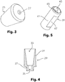
- the "reentrant screw” centralizer 25 will advantageously be in the form of a truncated cone pierced by a central duct on crossing on both sides in its longitudinal direction.
- Such a centraliser is represented in figure 3 .
- the led 27 has a diameter greater than that of the drill and has the function of positioning and guiding this drill.
- the figure 4 presents another embodiment of a centralizer 29 according to the invention for centering and guiding the drill in the case of so-called "outgoing" screws, in that they are in relief on the rim.
- the centralizer 29 "with outgoing screws” will then be in the form of a hollow socket, of cylindrical or frustoconical body 31, and traversed by a central duct 35 in communication with an internal cavity 33 opening on one of the ends of the body 31.
- the inner cavity 33 has an inner conical shape so that its diameter decreases along its length from its mouth. This configuration will allow the centraliser to cap the screw head and be retained on the latter.
- the central duct 35 of diameter greater than that of the drill shaft (and therefore of the extractor rod) is used for positioning and guiding said drill bit.
- the centralizer 29 has at the end opposite to that opening on the inner cavity 33 a protrusion 37 reproducing the shape of the head of the extractor, said protuberance 37 being traversed by said duct 35.
- This protuberance 37 allows the user to use a chuck to come to position and drive the centralizer 29 on the head of the screw.
- This impression centering device is in the form of a cylindrical body socket 41, and having on at least one of its ends an impression 43 of shape conjugated to a hexagonal screw head.
- the body 41 has a central duct 45 passing therethrough on both sides in its longitudinal direction.
- the conduit 45 has a diameter greater than that of the drill rod (and therefore the rod of the extractor) and is used for positioning and guiding the drill.
- the impression 43 will hold the head in position and prevent it from rotating under the action of the drill during the drilling operation.
- the body 31 has two diametrically opposite plates 47 to facilitate gripping and retention in position of the centraliser. More preferably, the centraliser has a fingerprint conjugated to a hexagonal screw head at each of its ends, said fingerprints having different dimensions.
- At least one of the centralizers is made of plastic material, for example polyoxymethylene (POM) to limit the risk of damaging the paint and varnish rims. Nevertheless, it is also possible to produce them in metallic materials.
- plastic material for example polyoxymethylene (POM)
- the extractor according to the invention can be put in place.
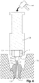
- the rod of the extractor is force-fitted into said bore during a step b) of fitting shown in FIG. figure 6 .
- the fitting is made by longitudinal sliding along the bore and this sliding is generated by percussion on the head of the extractor by means of a percussion tool, for example a hammer.
- the fitting of the extractor into the screw will couple in rotation the extractor and the screw.
- the step (b) of fitting is carried out by placing a striking mandrel 51 between the extractor 1 and the hammer 49.
- the striking mandrel 51 according to the invention comprises an end having a footprint 53 of shape conjugated to that of the head 7 of the extractor 1. The use of such a mandrel keeps the extractor in position for its fitting.
- the extractor 1 is fitted until the base of its head comes into abutment against the head 27 of the screw, or when the extractor has a sleeve 9 against the shoulder 11 formed by the sleeve 9 with the 3.
- This limitation of the depression of the extractor 1 ensures that the rod 3 thereof remains in the rod 21 of the screw 13. In fact, if the rod of the extractor exceeded the end of the screw shank, it would cling to the hub of the wheel which would make the loosening of the screw more difficult.
- step c) extraction (not shown) by means of a key cooperating with the head of the extractor .
- the straight character of the fitting associated with the extended contact surface makes it possible to obtain a loosening torque of at least 160 Nm, necessary for the loosening of the safety screws of the vehicle wheels.
- the step (c) of extracting the screw is followed by a step (d) of unhooking the extractor of the screw into which it has been fitted, preferably by use of a stall chuck 55 as shown in FIG. figure 7 .
- the separation of the screw 13 and the extractor 1 allows to reuse said extractor 1 for the extraction of another screw 13.
- the stall operation can be performed when the extractors 1 have a sleeve 9 defining a space between the head 23 of the screw 13 and the head 7 of the extractor 1.
- the stalling mandrel 55 has at one of its ends a fork 57 comprising two parallel teeth 59 of increasing thickness between their point 61 and their base 63.
- the spacing between the teeth 59 of the stalling mandrel 55 is chosen to be greater than the diameter of the sleeve 9 and less than the diameter of the head 7 of the extractor. In the case where the stall chuck is used with an extractor having no sleeve, the spacing between the teeth of the stall chuck must be greater than the diameter of the rod of said extractor.
- Step d) is illustrated on the figure 8 .
- the screw 13 is held by the jaws 65 of a vise.
- the stalling mandrel 55 is positioned to place the sleeve of the extractor 1 between its teeth 59.
- the sleeve is then pressed between the teeth 59 of the fork by percussion.
- the teeth 59 having an increasing height which at the base of said teeth is greater than the height of the sleeve, the depression of the extractor 1 will lift said extractor 1 to partially out of the screw 13.
Landscapes
- Engineering & Computer Science (AREA)
- Mechanical Engineering (AREA)
- Earth Drilling (AREA)
- Hand Tools For Fitting Together And Separating, Or Other Hand Tools (AREA)
Claims (13)
- Extraktionsverfahren einer Sicherheitsschraube oder einer gebrochenen Schraube, wobei die genannte Schraube (13) einen Stift (21) und eventuell einen Kopf (23) umfasst, wobei das Verfahren die folgenden Schritte umfasst:a) Bohren einer Ausbohrung (17) in der Schraube (13) gemäß der Längsrichtung derselben mittels einer Bohrnadel (19) mit einem Durchmesser des Stiftes (21) der Schraube (13);b) Einsetzen eines Extraktors (1) in die genannte Bohrung (17), wobei der Extraktor (1) einen gezahnten Stift (3) umfasst, dessen Zahnung die Form von länglichen Rippungen (5) und einen Kopf (7) aufweist, der an einem der Enden des genannten Stifts (3) befestigt ist, wobei das Einsetzen per Einfügen des Stifts (3) des Extraktors (1) in die genannte Ausbohrung (17) und per Stoßkraft auf den Kopf (7) des genannten Extraktors (1) mittels eines Stoßkraftwerkzeugs (49) derart erhalten wird, dass der Extraktor (1) und die Schraube (13) in Rotation gekoppelt werden;c) Extraktion der Schraube (13) per Lösen derselben mittels eines Schlüssels, der mit dem Kopf (7) des Extraktors zusammenwirkt;wobei das Verfahren dadurch gekennzeichnet ist, dass der Einsetzschritt (b) das Verwenden eines Schlag-Bohrfutters (51) umfasst, das zwischen dem Extraktor (1) und dem Stoßkraft-Werkzeug (49) angeordnet ist und dessen eines Ende eine Vertiefung (53) in einer Form aufweist, die mit der des Kopfes (7) des Extraktors (1) zusammenwirkt.
- Verfahren gemäß Anspruch 1, dadurch gekennzeichnet, dass der Schritt (a) zum Bohren der Ausbohrung (17) umfasst:- die Verwendung einer Bohrnadel (19), umfassend eine Spitze aus Wolframkarbid und / oder- dem ein Schritt zum Einsetzen eines Zentrierers (25, 29, 39) auf der Schraube (13) für die Positionierung und die Führung der Bohrnadel (19) vorangeht.
- Verfahren gemäß einem der Ansprüche 1 oder 2, dadurch gekennzeichnet, dass der Extraktor (1) einen Stutzen (9) umfasst, der an der Basis des Kopfes (7) angeordnet ist und einen größeren Durchmesser aufweist als den seines Stiftes (3) und einen kleineren als den seines Kopfes (7) derart, dass mit dem Stift (3) ein Ansatz (11) gebildet wird und dass der Schritt (b) zum Einsetzen das Einsetzen des Stiftes (3) des Extraktors (1) in die Schraube (13) umfasst, bis der genannte Ansatz (11) gegen die Schraube (13) im Anschlag platziert wird.
- Verfahren gemäß einem der Ansprüche 1 bis 3, dadurch gekennzeichnet, dass auf den Schritt (c) zum Extrahieren der Schraube (13) ein Schritt (c) zum Abnehmen des Extraktors (1) der Schraube (13) folgt, in dem er per Verwendung eines Abnehmstutzens (55) eingesetzt wird.
- Werkzeuggruppe zum Umsetzen des Verfahrens gemäß einem der Ansprüche 1 bis 4, umfassend:- wenigstens einen Extraktor (1), umfassend einen gezahnten Stift (3), dessen Zahnung (5) die Form von länglichen Rippungen (5) aufweist, und einen Kopf (7), der an einem der Enden des genannten Stiftes (3) befestigt ist;- wenigstens eine Bohrnadel (19) mit einem ähnlichen Durchmesser des Stiftes (3) des Extraktors (1) zum Bohren einer Ausbohrung (17) in der Schraube (13);- wenigstens ein Stoßkraftwerkzeug (49), das zum Stoßen des Kopfes (7) des genannten Extraktors (1) konfiguriert ist;- wenigstens einen Schlüssel, der zum Zusammenwirkenmit dem Kopf (7) des Extraktors (1) gestaltet ist; dadurch gekennzeichnet, dass die Werkzeuggruppe darüber hinaus umfasst:- ein Schlag-Bohrfutter (51) zum Einsetzen des Extraktors (1) in eine Ausbohrung (17), die in der Schraube (13) durchbohrt wird, wobei das genannte Schlag-Bohrfutter (51) an einem seiner Enden eine Vertiefung (53) in einer Form, die mit dem Kopf (7) des Extraktors (1) zusammenwirkt, aufweist;- einen oder mehrere Zentrierer (25, 29, 39) für die Positionierung und die Führung der Bohrnadeln (19) bei den Bohrarbeiten.
- Werkzeuggruppe gemäß Anspruch 5, dadurch gekennzeichnet, dass der Extraktor (1) darüber hinaus einen Stutzen (9) umfasst, der an der Basis des Kopfes (7) angeordnet ist, wobei der Stutzen (9) einen größeren Durchmesser aufweist als den des Stiftes (3) und einen kleineren als den des Kopfes (7) derart, dass mit dem Stift (3) ein Ansatz (11) gebildet wird; und / oder dass der Kopf (7) des Extraktors sechseckig ist.
- Gruppe gemäß Anspruch 5 oder 6, umfassend wenigstens eine Bohrnadel (19) mit einem ähnlichen Durchmesser als den Durchmesser des Stiftes (3) des Extraktors (1) zum Bohren einer Ausbohrung (17) in der Schraube (13), wobei die Gruppe dadurch gekennzeichnet ist, dass wenigstens eine der Bohrnadeln (19) eine Spitze aus Wolframkarbid aufweist.
- Werkzeuggruppe gemäß einem der Ansprüche 5 bis 7, umfassend wenigstens einen Zentrierer (25) für die Positionierung und die Führung einer Bohrnadel, wobei die Gruppe dadurch gekennzeichnet ist, dass wenigstens einer der Zentrierer (25) die Form eines kegelstumpfartigen Kegels aufweist, der auf jeder Seite gemäß der Längsrichtung durch einen zentralen Kanal (27) durchquert wird, wobei der genannte Kanal (27) einen größeren Durchmesser aufweist als den der Bohrnadel (19).
- Werkzeuggruppe gemäß einem der Ansprüche 5 bis 8, umfassend wenigstens einen Zentrierer (29) für die Positionierung und die Führung einer Bohrnadel, wobei die Gruppe dadurch gekennzeichnet ist, dass wenigstens einer der Zentrierer (29) die Form einer hohlen Buchse mit einem zylindrischen oder kegelstumpfartigen Körper aufweist, die von einem zentralen Kanal (35) mit einem größeren Durchmesser als dem der Bohrnadel (19) durchquert wird; wobei der genannte zentrale Kanal (35) mit einer internen Ausnehmung (33) in Verbindung steht, die auf einem der Enden des Körpers (31) münden, wobei die Mündung der internen Ausnehmung bemessen ist; um den Schraubenkopf zu überragen, der Zentrierer (29) bevorzugt an seinem Ende, das sich zur internen Ausnehmung (33) öffnet, eine Protuberanz (37) aufweist, die die Form des Kopfes (7) des Extraktors (1) wiedergibt, wobei die genannte Protuberanz (37) durch den genannten Kanal (35) durchquert wird.
- Werkzeuggruppe gemäß einem der Ansprüche 5 bis 9, umfassend wenigstens einen Zentrierer (39) für die Positionierung und die Führung einer Bohrnadel, wobei die Gruppe dadurch gekennzeichnet ist, dass wenigstens einer der Zentrierer (39) die Form eines zylindrischen Körpers (41) aufweist und an wenigstens einem seiner Enden eine Vertiefung (43) in einer Form aufweist, die mit dem Kopf der sechseckigen Schraube zusammenwirkt und gemäß seiner Länge von einem zentralen Kanal (45) durchquert wird, wobei der genannte Kanal (45) einen größeren Durchmesser aufweist als der der Bohrnadel (19), der zylindrische Körper bevorzugt zwei diametral entgegensetzte Platten aufweist.
- Werkzeuggruppe gemäß einem der Ansprüche 7 bis 10, dadurch gekennzeichnet, dass wenigstens einer der Zentrierer (25, 29, 39) aus Plastikmaterial, bevorzugt aus Polyoxymethylen (POM) ist.
- Werkzeuggruppe gemäß einem der Ansprüche 5 bis 11, umfassend ein Extraktions-Bohrfutter (55) zum Abnehmen des Extraktors (1) der Schraube (13), in der er eingesetzt ist, wobei die Gruppe dadurch gekennzeichnet ist, dass das genannte Extraktions-Bohrfutter (55) an einem seiner Enden eine Gabel (57) aufweist, die zwei Zähne (59) einer zwischen ihrer Spitze (61) und ihrer Basis (63) ansteigenden Dicke und die bevorzugt zwischen ihnen parallel sind, aufweist und dass die Beabstandung zwischen den Zähnen (59) des Abnehm-Bohrfutters (55) kleiner ist als der Durchmesser des Kopfes (7) des Extraktors (1).
- Verwendung einer Werkzeuggruppe gemäß einem der Ansprüche 5 bis 12 für die Extraktion einer Sicherheitsschraube oder einer gebrochenen Schraube auf einem Fahrzeugrad.
Priority Applications (8)
| Application Number | Priority Date | Filing Date | Title |
|---|---|---|---|
| DE16315008.9T DE16315008T1 (de) | 2016-09-09 | 2016-09-09 | Ausziehverfahren für eine sicherungsschraube und auszieher zur anwendung des verfahrens |
| EP16315008.9A EP3292958B1 (de) | 2016-09-09 | 2016-09-09 | Ausziehverfahren für eine sicherungsschraube und auszieher zur anwendung des verfahrens |
| ES16315008T ES2774470T3 (es) | 2016-09-09 | 2016-09-09 | Procedimiento de extracción de tornillos y extractor para la implementación del procedimiento |
| DK16315008.9T DK3292958T3 (da) | 2016-09-09 | 2016-09-09 | Fremgangsmåde til udtrækning af en skrue samt udtrækker til udøvelse af fremgangsmåden |
| FR1770354A FR3055823B3 (fr) | 2016-09-09 | 2017-04-07 | Procede d’extraction de vis de securite pour roues de vehicule automobile et extracteur pour la mise en œuvre du procede |
| BE20175246A BE1024703B1 (fr) | 2016-09-09 | 2017-04-07 | Procede d’extraction de vis de securite pour roues de vehicule automobile et extracteur pour la mise en oeuvre du procede |
| TW106130846A TWI746632B (zh) | 2016-09-09 | 2017-09-08 | 用於取出車輪用安全螺絲的方法、執行該方法的取出器及工具組以及取出器及工具組的用途 |
| US15/699,608 US10478952B2 (en) | 2016-09-09 | 2017-09-08 | Process for extracting security screw for wheels of motor vehicle and extractor for executing the process |
Applications Claiming Priority (1)
| Application Number | Priority Date | Filing Date | Title |
|---|---|---|---|
| EP16315008.9A EP3292958B1 (de) | 2016-09-09 | 2016-09-09 | Ausziehverfahren für eine sicherungsschraube und auszieher zur anwendung des verfahrens |
Publications (2)
| Publication Number | Publication Date |
|---|---|
| EP3292958A1 EP3292958A1 (de) | 2018-03-14 |
| EP3292958B1 true EP3292958B1 (de) | 2019-11-20 |
Family
ID=57047145
Family Applications (1)
| Application Number | Title | Priority Date | Filing Date |
|---|---|---|---|
| EP16315008.9A Active EP3292958B1 (de) | 2016-09-09 | 2016-09-09 | Ausziehverfahren für eine sicherungsschraube und auszieher zur anwendung des verfahrens |
Country Status (8)
| Country | Link |
|---|---|
| US (1) | US10478952B2 (de) |
| EP (1) | EP3292958B1 (de) |
| BE (1) | BE1024703B1 (de) |
| DE (1) | DE16315008T1 (de) |
| DK (1) | DK3292958T3 (de) |
| ES (1) | ES2774470T3 (de) |
| FR (1) | FR3055823B3 (de) |
| TW (1) | TWI746632B (de) |
Families Citing this family (4)
| Publication number | Priority date | Publication date | Assignee | Title |
|---|---|---|---|---|
| US20220040834A1 (en) * | 2016-04-27 | 2022-02-10 | Grip Holdings Llc | Fastener Extractor Device |
| JP7198467B2 (ja) * | 2018-08-21 | 2023-01-04 | グリップ・ホールディングズ・エルエルシー | ファスナー・エキストラクター |
| USD878882S1 (en) * | 2018-08-29 | 2020-03-24 | Chia-Hao Huang | Bolt extractor |
| CN112692788A (zh) * | 2021-03-01 | 2021-04-23 | 王伟 | 一种取锈死断螺丝方法 |
Family Cites Families (27)
| Publication number | Priority date | Publication date | Assignee | Title |
|---|---|---|---|---|
| US1875484A (en) * | 1932-09-06 | Schew extractor | ||
| US1798944A (en) * | 1930-09-11 | 1931-03-31 | Elmer F Jackman | Tool for removing broken stud bolts and the like |
| US4007795A (en) * | 1976-02-13 | 1977-02-15 | Skil Corporation | Attachment for a rotary-hammer tool |
| AU7062087A (en) * | 1986-05-09 | 1987-11-12 | Polonsky, E. | Removing broken threaded fasteners |
| US4688315A (en) * | 1986-05-28 | 1987-08-25 | Jannke Thomas E | Screw extractor and method of using same |
| US5031487A (en) | 1989-11-02 | 1991-07-16 | Alden Corporation | Broken bolt extractor |
| US5649791A (en) * | 1994-05-17 | 1997-07-22 | Connolly; Matthew | Apparatus and method for boring a hole in a broken bolt |
| DE19809252C2 (de) * | 1998-03-05 | 2000-04-06 | Robert Schroeder Gmbh & Co | Schraubenausdreher |
| US6098499A (en) * | 1998-07-16 | 2000-08-08 | The Lisle Corporation | Bolt extraction tool |
| US6602027B2 (en) * | 2001-09-26 | 2003-08-05 | Simp'l Products, Inc | Guides for centering screws and drill bits in countersink holes |
| US6575057B1 (en) * | 2002-04-18 | 2003-06-10 | Lisle Corporation | Broken heater hose coupler removal tool and method of use |
| US6978697B2 (en) * | 2003-04-25 | 2005-12-27 | Eazypower, Corporation | Damaged bolt and screw removing devices |
| US20060101949A1 (en) * | 2003-04-25 | 2006-05-18 | Burton Kozak | Damaged bolt and screw removing devices |
| US7007573B2 (en) * | 2004-05-12 | 2006-03-07 | Eazypower Corporation | Impact driver and fastener removal device |
| US20060060031A1 (en) * | 2004-09-23 | 2006-03-23 | Ron Morris | Broken bolt extractor apparatus and method |
| US7152509B2 (en) * | 2005-02-25 | 2006-12-26 | Irwin Industrial Tool Company | Fastener extractor |
| TWM290452U (en) * | 2005-11-09 | 2006-05-11 | Cosda Manu Facturing Company | Eject removing tool for bolt post |
| TWI333448B (en) * | 2008-03-27 | 2010-11-21 | Bo Shen Chen | New screw driver for removing broken screw |
| IT1393210B1 (it) | 2009-03-11 | 2012-04-11 | Groppo | Dispositivo di bloccaggio antifurto e suo metodo di realizzazione. |
| DE102011050671A1 (de) * | 2011-05-27 | 2012-11-29 | Wohn-t-räume UG (haftungsbeschränkt) | Hilfswerkzeug zum Einschlagen von Nägeln |
| US9839995B2 (en) * | 2011-09-26 | 2017-12-12 | Magna Industries, Inc. | Drain removal tool |
| TWM440846U (en) * | 2012-04-20 | 2012-11-11 | Li-Hua Huang | Connection rod structure with screw head removing function |
| TWM441553U (en) * | 2012-05-10 | 2012-11-21 | Giant Brand Entpr Co Ltd | A bit for removing damaged screws |
| DE102012104298B4 (de) * | 2012-05-18 | 2014-02-27 | Hafu Werkzeugfabrik H. J. Fuhrmann Gmbh | Werkzeug |
| TWM442238U (en) * | 2012-08-01 | 2012-12-01 | Shao-Hsien Hsu | Screw head capable of removing a dead screw |
| TWI436863B (zh) * | 2013-01-18 | 2014-05-11 | Fu Hua Lin | 拆卸工具 |
| US9352459B2 (en) * | 2014-04-04 | 2016-05-31 | Marvin Thomas | Broken bolt extractor |
-
2016
- 2016-09-09 EP EP16315008.9A patent/EP3292958B1/de active Active
- 2016-09-09 ES ES16315008T patent/ES2774470T3/es active Active
- 2016-09-09 DK DK16315008.9T patent/DK3292958T3/da active
- 2016-09-09 DE DE16315008.9T patent/DE16315008T1/de active Pending
-
2017
- 2017-04-07 BE BE20175246A patent/BE1024703B1/fr active IP Right Grant
- 2017-04-07 FR FR1770354A patent/FR3055823B3/fr not_active Expired - Fee Related
- 2017-09-08 US US15/699,608 patent/US10478952B2/en active Active
- 2017-09-08 TW TW106130846A patent/TWI746632B/zh active
Non-Patent Citations (1)
| Title |
|---|
| None * |
Also Published As
| Publication number | Publication date |
|---|---|
| US10478952B2 (en) | 2019-11-19 |
| FR3055823B3 (fr) | 2018-12-07 |
| BE1024703B1 (fr) | 2018-06-07 |
| EP3292958A1 (de) | 2018-03-14 |
| TWI746632B (zh) | 2021-11-21 |
| US20180071903A1 (en) | 2018-03-15 |
| ES2774470T3 (es) | 2020-07-21 |
| BE1024703A1 (fr) | 2018-05-29 |
| DK3292958T3 (da) | 2020-03-02 |
| TW201815525A (zh) | 2018-05-01 |
| FR3055823A3 (fr) | 2018-03-16 |
| DE16315008T1 (de) | 2019-01-03 |
Similar Documents
| Publication | Publication Date | Title |
|---|---|---|
| EP3292958B1 (de) | Ausziehverfahren für eine sicherungsschraube und auszieher zur anwendung des verfahrens | |
| EP0712667B1 (de) | Zentrifuge mit abnehmbarem Rotor und einer Einrichtung zur axialen Verriegelung des Rotors auf der Antriebswelle | |
| CH644049A5 (fr) | Manche destine a etre utilise en liaison avec un outil en forme de ''l''. | |
| FR2815386A1 (fr) | Dispositif d'ecrous anti-desserrage | |
| WO2009138627A1 (fr) | Dispositif de fixation antivol de solidarisation d'une roue sur le moyeu d'un vehicule automobile | |
| FR2963269A1 (fr) | Dispositif d'extraction et d'insertion d'une goupille, procedes d'extraction et d'insertion associes | |
| FR2792042A3 (fr) | Clou | |
| EP0573766A1 (de) | Universalspannfutter für eine Schachtofenabstichbohrmaschine | |
| EP0706442A1 (de) | Werkzeug zum anziehen von befestigungsmitteln, insbesondere schraubendreher | |
| CH643323A5 (fr) | Adaptateur utilisable pour enfoncer des tuyaux dans le sol. | |
| WO2015159034A2 (fr) | Dispositif de fixation antivol de solidarisation d'une roue sur le moyeu d'un véhicule automobile | |
| US20120000320A1 (en) | Spinning lug stud socket | |
| FR2832656A1 (fr) | Mors de serrage pour mandrin de percage, en particulier pour mandrin de perceuse a percussion | |
| EP0615819A1 (de) | Schlagwerkzeuggriffschutz und sein Montageverfahren | |
| FR2766163A1 (fr) | Bouchon a extraction facile et son extracteur | |
| EP1722929B1 (de) | Greifklemmende für eine schraubvorrichtung | |
| FR2589959A1 (fr) | Dispositif pour bloquer de facon detachable l'assemblage d'une piece cylindrique concave et d'une piece cylindrique convexe | |
| FR3055919A1 (fr) | Dispositif de forage de sol pour la realisation d'essais d'expansion en forage d'un sol in situ | |
| FR3055236B1 (fr) | Outil d’entrainement en rotation de vis filetee | |
| EP0314544A1 (de) | Spannfutter, insbesondere für Maschinen mit automatischem Vorschub | |
| FR2955907A1 (fr) | Dispositif de fixation antivol de solidarisation d'une roue sur le moyeu d'un vehicule automobile. | |
| FR2972131A1 (fr) | Dispositif d'assemblage | |
| FR3128145A1 (fr) | Installation pour le maintien d’un engin roulant à deux ou trois roues en vue d’une intervention sur ledit engin | |
| FR2509449A1 (fr) | Dispositif d'accouplement d'une tige de percage du trou de coulee d'un four a cuve a l'outil de travail d'une machine de percage | |
| WO2013128090A2 (fr) | Pince de maintien constitutive d'un dispositif de verrouillage et/ou de déverrouillage d'une tête d'un outil, tel qu'un carottier |
Legal Events
| Date | Code | Title | Description |
|---|---|---|---|
| PUAI | Public reference made under article 153(3) epc to a published international application that has entered the european phase |
Free format text: ORIGINAL CODE: 0009012 |
|
| STAA | Information on the status of an ep patent application or granted ep patent |
Free format text: STATUS: THE APPLICATION HAS BEEN PUBLISHED |
|
| AK | Designated contracting states |
Kind code of ref document: A1 Designated state(s): AL AT BE BG CH CY CZ DE DK EE ES FI FR GB GR HR HU IE IS IT LI LT LU LV MC MK MT NL NO PL PT RO RS SE SI SK SM TR |
|
| AX | Request for extension of the european patent |
Extension state: BA ME |
|
| STAA | Information on the status of an ep patent application or granted ep patent |
Free format text: STATUS: REQUEST FOR EXAMINATION WAS MADE |
|
| RBV | Designated contracting states (corrected) |
Designated state(s): AL AT BE BG CH CY CZ DE DK EE ES FI FR GB GR HR HU IE IS IT LI LT LU LV MC MK MT NL NO PL PT RO RS SE SI SK SM TR |
|
| 17P | Request for examination filed |
Effective date: 20180911 |
|
| REG | Reference to a national code |
Ref document number: 602016024615 Country of ref document: DE Ref country code: DE Ref legal event code: R210 |
|
| STAA | Information on the status of an ep patent application or granted ep patent |
Free format text: STATUS: EXAMINATION IS IN PROGRESS |
|
| 17Q | First examination report despatched |
Effective date: 20190415 |
|
| RIC1 | Information provided on ipc code assigned before grant |
Ipc: B25B 27/18 20060101AFI20190717BHEP Ipc: B25B 23/10 20060101ALI20190717BHEP |
|
| GRAP | Despatch of communication of intention to grant a patent |
Free format text: ORIGINAL CODE: EPIDOSNIGR1 |
|
| STAA | Information on the status of an ep patent application or granted ep patent |
Free format text: STATUS: GRANT OF PATENT IS INTENDED |
|
| INTG | Intention to grant announced |
Effective date: 20190827 |
|
| GRAA | (expected) grant |
Free format text: ORIGINAL CODE: 0009210 |
|
| STAA | Information on the status of an ep patent application or granted ep patent |
Free format text: STATUS: THE PATENT HAS BEEN GRANTED |
|
| GRAS | Grant fee paid |
Free format text: ORIGINAL CODE: EPIDOSNIGR3 |
|
| REG | Reference to a national code |
Ref country code: DE Ref legal event code: R082 Ref document number: 602016024615 Country of ref document: DE |
|
| AK | Designated contracting states |
Kind code of ref document: B1 Designated state(s): AL AT BE BG CH CY CZ DE DK EE ES FI FR GB GR HR HU IE IS IT LI LT LU LV MC MK MT NL NO PL PT RO RS SE SI SK SM TR |
|
| REG | Reference to a national code |
Ref country code: GB Ref legal event code: FG4D Free format text: NOT ENGLISH |
|
| REG | Reference to a national code |
Ref country code: CH Ref legal event code: EP |
|
| REG | Reference to a national code |
Ref country code: IE Ref legal event code: FG4D Free format text: LANGUAGE OF EP DOCUMENT: FRENCH |
|
| REG | Reference to a national code |
Ref country code: DE Ref legal event code: R096 Ref document number: 602016024615 Country of ref document: DE |
|
| REG | Reference to a national code |
Ref country code: AT Ref legal event code: REF Ref document number: 1203672 Country of ref document: AT Kind code of ref document: T Effective date: 20191215 |
|
| REG | Reference to a national code |
Ref country code: DK Ref legal event code: T3 Effective date: 20200225 |
|
| REG | Reference to a national code |
Ref country code: NL Ref legal event code: FP |
|
| REG | Reference to a national code |
Ref country code: LT Ref legal event code: MG4D |
|
| PG25 | Lapsed in a contracting state [announced via postgrant information from national office to epo] |
Ref country code: FI Free format text: LAPSE BECAUSE OF FAILURE TO SUBMIT A TRANSLATION OF THE DESCRIPTION OR TO PAY THE FEE WITHIN THE PRESCRIBED TIME-LIMIT Effective date: 20191120 Ref country code: LT Free format text: LAPSE BECAUSE OF FAILURE TO SUBMIT A TRANSLATION OF THE DESCRIPTION OR TO PAY THE FEE WITHIN THE PRESCRIBED TIME-LIMIT Effective date: 20191120 Ref country code: BG Free format text: LAPSE BECAUSE OF FAILURE TO SUBMIT A TRANSLATION OF THE DESCRIPTION OR TO PAY THE FEE WITHIN THE PRESCRIBED TIME-LIMIT Effective date: 20200220 Ref country code: SE Free format text: LAPSE BECAUSE OF FAILURE TO SUBMIT A TRANSLATION OF THE DESCRIPTION OR TO PAY THE FEE WITHIN THE PRESCRIBED TIME-LIMIT Effective date: 20191120 Ref country code: NO Free format text: LAPSE BECAUSE OF FAILURE TO SUBMIT A TRANSLATION OF THE DESCRIPTION OR TO PAY THE FEE WITHIN THE PRESCRIBED TIME-LIMIT Effective date: 20200220 Ref country code: LV Free format text: LAPSE BECAUSE OF FAILURE TO SUBMIT A TRANSLATION OF THE DESCRIPTION OR TO PAY THE FEE WITHIN THE PRESCRIBED TIME-LIMIT Effective date: 20191120 Ref country code: GR Free format text: LAPSE BECAUSE OF FAILURE TO SUBMIT A TRANSLATION OF THE DESCRIPTION OR TO PAY THE FEE WITHIN THE PRESCRIBED TIME-LIMIT Effective date: 20200221 |
|
| PG25 | Lapsed in a contracting state [announced via postgrant information from national office to epo] |
Ref country code: HR Free format text: LAPSE BECAUSE OF FAILURE TO SUBMIT A TRANSLATION OF THE DESCRIPTION OR TO PAY THE FEE WITHIN THE PRESCRIBED TIME-LIMIT Effective date: 20191120 Ref country code: RS Free format text: LAPSE BECAUSE OF FAILURE TO SUBMIT A TRANSLATION OF THE DESCRIPTION OR TO PAY THE FEE WITHIN THE PRESCRIBED TIME-LIMIT Effective date: 20191120 Ref country code: IS Free format text: LAPSE BECAUSE OF FAILURE TO SUBMIT A TRANSLATION OF THE DESCRIPTION OR TO PAY THE FEE WITHIN THE PRESCRIBED TIME-LIMIT Effective date: 20200320 |
|
| PG25 | Lapsed in a contracting state [announced via postgrant information from national office to epo] |
Ref country code: AL Free format text: LAPSE BECAUSE OF FAILURE TO SUBMIT A TRANSLATION OF THE DESCRIPTION OR TO PAY THE FEE WITHIN THE PRESCRIBED TIME-LIMIT Effective date: 20191120 |
|
| REG | Reference to a national code |
Ref country code: ES Ref legal event code: FG2A Ref document number: 2774470 Country of ref document: ES Kind code of ref document: T3 Effective date: 20200721 |
|
| PG25 | Lapsed in a contracting state [announced via postgrant information from national office to epo] |
Ref country code: CZ Free format text: LAPSE BECAUSE OF FAILURE TO SUBMIT A TRANSLATION OF THE DESCRIPTION OR TO PAY THE FEE WITHIN THE PRESCRIBED TIME-LIMIT Effective date: 20191120 Ref country code: RO Free format text: LAPSE BECAUSE OF FAILURE TO SUBMIT A TRANSLATION OF THE DESCRIPTION OR TO PAY THE FEE WITHIN THE PRESCRIBED TIME-LIMIT Effective date: 20191120 Ref country code: EE Free format text: LAPSE BECAUSE OF FAILURE TO SUBMIT A TRANSLATION OF THE DESCRIPTION OR TO PAY THE FEE WITHIN THE PRESCRIBED TIME-LIMIT Effective date: 20191120 Ref country code: PT Free format text: LAPSE BECAUSE OF FAILURE TO SUBMIT A TRANSLATION OF THE DESCRIPTION OR TO PAY THE FEE WITHIN THE PRESCRIBED TIME-LIMIT Effective date: 20200412 |
|
| REG | Reference to a national code |
Ref country code: DE Ref legal event code: R097 Ref document number: 602016024615 Country of ref document: DE |
|
| PG25 | Lapsed in a contracting state [announced via postgrant information from national office to epo] |
Ref country code: SK Free format text: LAPSE BECAUSE OF FAILURE TO SUBMIT A TRANSLATION OF THE DESCRIPTION OR TO PAY THE FEE WITHIN THE PRESCRIBED TIME-LIMIT Effective date: 20191120 Ref country code: SM Free format text: LAPSE BECAUSE OF FAILURE TO SUBMIT A TRANSLATION OF THE DESCRIPTION OR TO PAY THE FEE WITHIN THE PRESCRIBED TIME-LIMIT Effective date: 20191120 |
|
| PLBE | No opposition filed within time limit |
Free format text: ORIGINAL CODE: 0009261 |
|
| STAA | Information on the status of an ep patent application or granted ep patent |
Free format text: STATUS: NO OPPOSITION FILED WITHIN TIME LIMIT |
|
| 26N | No opposition filed |
Effective date: 20200821 |
|
| PG25 | Lapsed in a contracting state [announced via postgrant information from national office to epo] |
Ref country code: SI Free format text: LAPSE BECAUSE OF FAILURE TO SUBMIT A TRANSLATION OF THE DESCRIPTION OR TO PAY THE FEE WITHIN THE PRESCRIBED TIME-LIMIT Effective date: 20191120 Ref country code: PL Free format text: LAPSE BECAUSE OF FAILURE TO SUBMIT A TRANSLATION OF THE DESCRIPTION OR TO PAY THE FEE WITHIN THE PRESCRIBED TIME-LIMIT Effective date: 20191120 |
|
| REG | Reference to a national code |
Ref country code: CH Ref legal event code: PL |
|
| REG | Reference to a national code |
Ref country code: BE Ref legal event code: MM Effective date: 20200930 |
|
| PG25 | Lapsed in a contracting state [announced via postgrant information from national office to epo] |
Ref country code: LI Free format text: LAPSE BECAUSE OF NON-PAYMENT OF DUE FEES Effective date: 20200930 Ref country code: IE Free format text: LAPSE BECAUSE OF NON-PAYMENT OF DUE FEES Effective date: 20200909 Ref country code: CH Free format text: LAPSE BECAUSE OF NON-PAYMENT OF DUE FEES Effective date: 20200930 Ref country code: BE Free format text: LAPSE BECAUSE OF NON-PAYMENT OF DUE FEES Effective date: 20200930 |
|
| PGFP | Annual fee paid to national office [announced via postgrant information from national office to epo] |
Ref country code: LU Payment date: 20210921 Year of fee payment: 6 |
|
| PG25 | Lapsed in a contracting state [announced via postgrant information from national office to epo] |
Ref country code: TR Free format text: LAPSE BECAUSE OF FAILURE TO SUBMIT A TRANSLATION OF THE DESCRIPTION OR TO PAY THE FEE WITHIN THE PRESCRIBED TIME-LIMIT Effective date: 20191120 Ref country code: MT Free format text: LAPSE BECAUSE OF FAILURE TO SUBMIT A TRANSLATION OF THE DESCRIPTION OR TO PAY THE FEE WITHIN THE PRESCRIBED TIME-LIMIT Effective date: 20191120 Ref country code: CY Free format text: LAPSE BECAUSE OF FAILURE TO SUBMIT A TRANSLATION OF THE DESCRIPTION OR TO PAY THE FEE WITHIN THE PRESCRIBED TIME-LIMIT Effective date: 20191120 |
|
| PG25 | Lapsed in a contracting state [announced via postgrant information from national office to epo] |
Ref country code: MK Free format text: LAPSE BECAUSE OF FAILURE TO SUBMIT A TRANSLATION OF THE DESCRIPTION OR TO PAY THE FEE WITHIN THE PRESCRIBED TIME-LIMIT Effective date: 20191120 Ref country code: MC Free format text: LAPSE BECAUSE OF FAILURE TO SUBMIT A TRANSLATION OF THE DESCRIPTION OR TO PAY THE FEE WITHIN THE PRESCRIBED TIME-LIMIT Effective date: 20191120 |
|
| P01 | Opt-out of the competence of the unified patent court (upc) registered |
Effective date: 20230328 |
|
| P02 | Opt-out of the competence of the unified patent court (upc) changed |
Effective date: 20230417 |
|
| PG25 | Lapsed in a contracting state [announced via postgrant information from national office to epo] |
Ref country code: LU Free format text: LAPSE BECAUSE OF NON-PAYMENT OF DUE FEES Effective date: 20220909 |
|
| PGFP | Annual fee paid to national office [announced via postgrant information from national office to epo] |
Ref country code: NL Payment date: 20230920 Year of fee payment: 8 Ref country code: GB Payment date: 20230920 Year of fee payment: 8 Ref country code: AT Payment date: 20230921 Year of fee payment: 8 |
|
| PGFP | Annual fee paid to national office [announced via postgrant information from national office to epo] |
Ref country code: FR Payment date: 20230928 Year of fee payment: 8 Ref country code: DK Payment date: 20230925 Year of fee payment: 8 Ref country code: DE Payment date: 20230920 Year of fee payment: 8 |
|
| PGFP | Annual fee paid to national office [announced via postgrant information from national office to epo] |
Ref country code: ES Payment date: 20231124 Year of fee payment: 8 |
|
| PGFP | Annual fee paid to national office [announced via postgrant information from national office to epo] |
Ref country code: IT Payment date: 20230927 Year of fee payment: 8 |