EP3292016B1 - Akkuinduktivladevorrichtung - Google Patents
Akkuinduktivladevorrichtung Download PDFInfo
- Publication number
- EP3292016B1 EP3292016B1 EP16715509.2A EP16715509A EP3292016B1 EP 3292016 B1 EP3292016 B1 EP 3292016B1 EP 16715509 A EP16715509 A EP 16715509A EP 3292016 B1 EP3292016 B1 EP 3292016B1
- Authority
- EP
- European Patent Office
- Prior art keywords
- inductive charging
- unit
- rechargeable battery
- intended
- voltage
- Prior art date
- Legal status (The legal status is an assumption and is not a legal conclusion. Google has not performed a legal analysis and makes no representation as to the accuracy of the status listed.)
- Not-in-force
Links
Images


Classifications
-
- B—PERFORMING OPERATIONS; TRANSPORTING
- B60—VEHICLES IN GENERAL
- B60L—PROPULSION OF ELECTRICALLY-PROPELLED VEHICLES; SUPPLYING ELECTRIC POWER FOR AUXILIARY EQUIPMENT OF ELECTRICALLY-PROPELLED VEHICLES; ELECTRODYNAMIC BRAKE SYSTEMS FOR VEHICLES IN GENERAL; MAGNETIC SUSPENSION OR LEVITATION FOR VEHICLES; MONITORING OPERATING VARIABLES OF ELECTRICALLY-PROPELLED VEHICLES; ELECTRIC SAFETY DEVICES FOR ELECTRICALLY-PROPELLED VEHICLES
- B60L1/00—Supplying electric power to auxiliary equipment of vehicles
- B60L1/006—Supplying electric power to auxiliary equipment of vehicles to power outlets
-
- B—PERFORMING OPERATIONS; TRANSPORTING
- B60—VEHICLES IN GENERAL
- B60R—VEHICLES, VEHICLE FITTINGS, OR VEHICLE PARTS, NOT OTHERWISE PROVIDED FOR
- B60R16/00—Electric or fluid circuits specially adapted for vehicles and not otherwise provided for; Arrangement of elements of electric or fluid circuits specially adapted for vehicles and not otherwise provided for
- B60R16/02—Electric or fluid circuits specially adapted for vehicles and not otherwise provided for; Arrangement of elements of electric or fluid circuits specially adapted for vehicles and not otherwise provided for electric constitutive elements
- B60R16/03—Electric or fluid circuits specially adapted for vehicles and not otherwise provided for; Arrangement of elements of electric or fluid circuits specially adapted for vehicles and not otherwise provided for electric constitutive elements for supply of electrical power to vehicle subsystems or for
-
- H—ELECTRICITY
- H02—GENERATION; CONVERSION OR DISTRIBUTION OF ELECTRIC POWER
- H02J—ELECTRIC POWER NETWORKS; CIRCUIT ARRANGEMENTS OR SYSTEMS FOR SUPPLYING OR DISTRIBUTING ELECTRIC POWER; SYSTEMS FOR STORING ELECTRIC ENERGY
- H02J50/00—Circuit arrangements or systems for wireless supply or distribution of electric power
- H02J50/10—Circuit arrangements or systems for wireless supply or distribution of electric power using inductive coupling
-
- H—ELECTRICITY
- H02—GENERATION; CONVERSION OR DISTRIBUTION OF ELECTRIC POWER
- H02J—ELECTRIC POWER NETWORKS; CIRCUIT ARRANGEMENTS OR SYSTEMS FOR SUPPLYING OR DISTRIBUTING ELECTRIC POWER; SYSTEMS FOR STORING ELECTRIC ENERGY
- H02J7/00—Circuit arrangements for charging or discharging batteries or for supplying loads from batteries
- H02J7/70—Circuit arrangements for charging or discharging batteries or for supplying loads from batteries characterised by the mechanical construction
- H02J7/731—Circuit arrangements for charging or discharging batteries or for supplying loads from batteries characterised by the mechanical construction specially adapted for holding portable devices containing batteries
-
- H—ELECTRICITY
- H02—GENERATION; CONVERSION OR DISTRIBUTION OF ELECTRIC POWER
- H02J—ELECTRIC POWER NETWORKS; CIRCUIT ARRANGEMENTS OR SYSTEMS FOR SUPPLYING OR DISTRIBUTING ELECTRIC POWER; SYSTEMS FOR STORING ELECTRIC ENERGY
- H02J2105/00—Networks for supplying or distributing electric power characterised by their spatial reach or by the load
- H02J2105/30—Networks for supplying or distributing electric power characterised by their spatial reach or by the load the load networks being external to vehicles, i.e. exchanging power with vehicles
- H02J2105/33—Networks for supplying or distributing electric power characterised by their spatial reach or by the load the load networks being external to vehicles, i.e. exchanging power with vehicles exchanging power with road vehicles
-
- Y—GENERAL TAGGING OF NEW TECHNOLOGICAL DEVELOPMENTS; GENERAL TAGGING OF CROSS-SECTIONAL TECHNOLOGIES SPANNING OVER SEVERAL SECTIONS OF THE IPC; TECHNICAL SUBJECTS COVERED BY FORMER USPC CROSS-REFERENCE ART COLLECTIONS [XRACs] AND DIGESTS
- Y02—TECHNOLOGIES OR APPLICATIONS FOR MITIGATION OR ADAPTATION AGAINST CLIMATE CHANGE
- Y02T—CLIMATE CHANGE MITIGATION TECHNOLOGIES RELATED TO TRANSPORTATION
- Y02T10/00—Road transport of goods or passengers
- Y02T10/60—Other road transportation technologies with climate change mitigation effect
- Y02T10/70—Energy storage systems for electromobility, e.g. batteries
-
- Y—GENERAL TAGGING OF NEW TECHNOLOGICAL DEVELOPMENTS; GENERAL TAGGING OF CROSS-SECTIONAL TECHNOLOGIES SPANNING OVER SEVERAL SECTIONS OF THE IPC; TECHNICAL SUBJECTS COVERED BY FORMER USPC CROSS-REFERENCE ART COLLECTIONS [XRACs] AND DIGESTS
- Y02—TECHNOLOGIES OR APPLICATIONS FOR MITIGATION OR ADAPTATION AGAINST CLIMATE CHANGE
- Y02T—CLIMATE CHANGE MITIGATION TECHNOLOGIES RELATED TO TRANSPORTATION
- Y02T10/00—Road transport of goods or passengers
- Y02T10/60—Other road transportation technologies with climate change mitigation effect
- Y02T10/7072—Electromobility specific charging systems or methods for batteries, ultracapacitors, supercapacitors or double-layer capacitors
-
- Y—GENERAL TAGGING OF NEW TECHNOLOGICAL DEVELOPMENTS; GENERAL TAGGING OF CROSS-SECTIONAL TECHNOLOGIES SPANNING OVER SEVERAL SECTIONS OF THE IPC; TECHNICAL SUBJECTS COVERED BY FORMER USPC CROSS-REFERENCE ART COLLECTIONS [XRACs] AND DIGESTS
- Y02—TECHNOLOGIES OR APPLICATIONS FOR MITIGATION OR ADAPTATION AGAINST CLIMATE CHANGE
- Y02T—CLIMATE CHANGE MITIGATION TECHNOLOGIES RELATED TO TRANSPORTATION
- Y02T90/00—Enabling technologies or technologies with a potential or indirect contribution to GHG emissions mitigation
- Y02T90/10—Technologies relating to charging of electric vehicles
- Y02T90/12—Electric charging stations
-
- Y—GENERAL TAGGING OF NEW TECHNOLOGICAL DEVELOPMENTS; GENERAL TAGGING OF CROSS-SECTIONAL TECHNOLOGIES SPANNING OVER SEVERAL SECTIONS OF THE IPC; TECHNICAL SUBJECTS COVERED BY FORMER USPC CROSS-REFERENCE ART COLLECTIONS [XRACs] AND DIGESTS
- Y02—TECHNOLOGIES OR APPLICATIONS FOR MITIGATION OR ADAPTATION AGAINST CLIMATE CHANGE
- Y02T—CLIMATE CHANGE MITIGATION TECHNOLOGIES RELATED TO TRANSPORTATION
- Y02T90/00—Enabling technologies or technologies with a potential or indirect contribution to GHG emissions mitigation
- Y02T90/10—Technologies relating to charging of electric vehicles
- Y02T90/14—Plug-in electric vehicles
Definitions
- the inductive charging unit is provided for an energy supply by the DC voltage converter. From the DE 10 2012 206 728 A1 it is also known that the inductive charging unit there comprises a functional unit which can automatically detect a frequency of an applied supply voltage of the vehicle to distinguish between a direct voltage and an alternating voltage.
- a battery inductive charging device is proposed with an inductive charging unit for charging a handheld power tool, a household appliance, a handheld power tool battery pack or a household appliance battery pack positioned relative to the inductive charging unit.
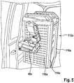
- the holding unit has at least one translation unit, which is provided to translate a force of gravity into a positioning force acting essentially perpendicular to the force of gravity. In this way, safe and uninterrupted inductive charging with simple means can be made possible for the operator while a vehicle is in motion.
- the handheld power tool, the household appliance, the handheld power tool battery pack or the household appliance battery pack can be brought into a charging position particularly easily and / or quickly.
- essentially perpendicular is to be understood in particular that the directions of the force of gravity and the positioning force form an angle in a range from 70 degrees to 110 degrees, preferably in a range from 80 degrees to 100 degrees and particularly preferably in a range of Include 85 degrees to 95 degrees.
- a “positioning force” is to be understood in particular as a force which acts on the inductive charging unit, the battery pack, the handheld power tool or the domestic appliance in the direction of a charging position.
- a "direction of gravity” in this context is to be understood in particular as a direction in which gravity acts on elements arranged in the vehicle, with an orientation provided for the vehicle relative to a gravitational field in which a floor of the vehicle is at least substantially is aligned parallel to a surface of the earth.
- a “vehicle” is to be understood in particular as a motor vehicle, preferably a road motor vehicle.
- an “inductive charging unit” should be understood to mean a unit for charging a battery pack or a handheld power tool, which is provided to pass on a charging current by electromagnetic induction in at least one charging state.
- the induction unit preferably comprises an induction coil designed as a primary coil, which is provided to generate a magnetic field in at least one operating state by an applied electrical energy, in particular by an alternating voltage, which generates an alternating electrical current in an induction coil of the battery pack or the handheld power tool.
- the induction coil is provided to convert an electromagnetic alternating field into an electrical alternating current and / or vice versa.
- the alternating field preferably has a frequency of 10-500 kHz, particularly preferably 100-120 kHz.
- the inductive charging unit preferably comprises at least one core element for increasing an inductance of the at least one induction coil.
- a “battery pack” is to be understood in particular as an energy storage unit, in particular an energy storage unit designed as an inductive charging battery pack, which has an induction coil designed as a secondary coil.
- the battery pack is preferably designed as a handheld power tool battery pack or as a domestic appliance battery pack and is provided for a machine, in particular to supply a handheld power tool and / or a household appliance with electrical energy.
- the battery pack is preferably provided to supply at least one electrical drive unit of the machine with electrical energy.
- the battery pack is preferably provided for temporarily storing electrical energy.
- a "hand machine tool” should in particular mean a drill, a drill and / or hammer, a saw, a planer, a screwdriver, a milling machine, a grinder, an angle grinder, a gardening implement, in particular a mower, a vacuum cleaner and / or a multi-function tool.
- a “household appliance” is to be understood in particular as a device that is intended to be used in a household, and in particular to perform and / or support housework and / or for personal hygiene, entertainment, sporting activity and / or information transfer is provided.
- a “DC voltage converter” is to be understood in particular as a unit which is provided for converting an input current having a direct voltage into an output current having a direct voltage.
- the DC / DC converter preferably has an energy buffer store and switching electronics.
- “Provided” is to be understood in particular as specifically programmed, designed and / or equipped. The fact that an object is provided for a specific function should be understood in particular to mean that the object fulfills and / or executes this specific function in at least one application and / or operating state.
- the DC voltage converter is provided to convert a voltage of an energy store into a higher voltage for supplying the inductive charging unit.
- an existing inductive charging unit can advantageously be used in a vehicle.
- Low development costs and / or production costs can be achieved.
- An advantageous use of the energy store can be achieved.
- an “energy store” is to be understood in particular as a low-voltage energy store, for example a lead-acid battery.
- the energy store is preferably provided for supplying energy to an on-board network of the vehicle.
- the energy store preferably has an output voltage between 12 V and 24 V inclusive.
- the DC voltage converter is preferably provided for an input voltage of less than or equal to 30 V, preferably less than or equal to 24 V and particularly preferably less than or equal to 12 V.
- the DC voltage converter preferably has at least a current output with an output voltage of at least 230 V, preferably of at least 250 V and particularly preferably of at least 300 V and very particularly preferably of at least 325 V. It is conceivable that the DC voltage converter has a plurality of current outputs. It is conceivable that the current outputs of the DC voltage converter have at least essentially the same output voltage or different output voltages.
- the DC-DC converter and the inductive charging unit preferably have housings that are designed separately from one another.
- the battery inductive charging device can comprise at least one unit with a housing, in which the at least one DC voltage converter and the at least one inductive charging unit are arranged.
- the battery inductive charging device preferably comprises at least one unit with a housing, in which the at least one DC voltage converter and a plurality of inductive charging units, in particular two inductive charging units, are arranged.
- the inductive charging unit is advantageously provided to be supplied with either direct current or alternating current. As a result, a particularly versatile battery inductive charging device can be provided. Development and / or production costs can be further reduced. User convenience can be further increased.
- the inductive charging unit is preferably provided for a supply with a mains voltage which has an effective voltage of approximately 230 V and a frequency of approximately 50 Hz.
- the battery inductive charging device comprises a plurality of inductive charging units, which are provided for an energy supply by at least one DC voltage converter.
- a plurality of battery packs can be charged at the same time or a plurality of battery packs can be arranged in a charging position at the same time, regardless of a charging sequence.
- the efficiency of the battery inductive charging device can be increased further.
- a number of parts and / or a number of electrical connecting lines can be kept small.
- a particularly inexpensive battery inductive charging device can be provided.
- the battery inductive charging device preferably has a plurality of electrical connecting lines which, in an assembled state, connect the DC voltage converter to an inductive charging unit in each case.
- the battery inductive charging device advantageously comprises a distributor unit which has a plurality of connections which are provided at least for a temporary connection to one inductive charging unit in each case.
- a plurality of battery packs can be charged particularly easily. Replacement battery packs can be charged. Battery packs for handheld power tools and / or household appliances can be charged for different uses.
- a short electrical connection cable can be achieved between the energy store and the DC voltage converter. Metallic conductor material, in particular copper, can be saved. Power loss can be limited.
- the distribution unit is arranged between the DC / DC converter and the plurality of inductive charging units in relation to an energy flow.
- a rechargeable battery inductive charging device has a plug connection which is provided to connect the inductive charging unit, optionally to the distributor unit or to a mains connection.
- the battery inductive charging unit can be operated particularly easily with a mains connection.
- “connect” is to be understood in particular to be an electrical connection, in particular to connect to a power transmission.
- a “plug connection” is to be understood in particular as a connection that can be detached without tools. It is conceivable that the plug connection has at least one adapter which is provided to connect the inductive unit to the distributor unit or the mains connection.
- the battery inductive charging unit advantageously includes a charging bay which includes the inductive charging unit and is provided for receiving a hand tool case.
- a battery inductive charging device can be provided for a wide range of applications. Use of the battery inductive charging device can be further simplified.
- a “loading bay” is to be understood in particular as a unit which is provided to store the hand tool case for charging, storage and / or transport, preferably in a building or in a vehicle.
- the hand tool case and the loading bay are preferably designed to be fixed, preferably without tools, so that they can be connected to one another.
- the hand tool case and the loading bay are preferably designed to be non-destructive, preferably separable from one another without tools.
- the hand tool case is preferably due to gravity and / or by means of a Latching connection and / or held in the loading bay by means of a clamping device.
- the loading bay is preferably provided for assembly in a storage system, for example in a shelving system and / or in a rack system.
- the charging bay preferably has a plurality of inductive charging units, preferably two inductive charging units.
- a "hand tool case” is to be understood in particular as a case that can be carried by hand and is provided to protect a transport object stored in a suitcase interior, in particular a battery pack, a hand machine tool and / or a household appliance, or a plurality of transport objects from dust, To protect moisture, mechanical effects and / or other environmental influences.
- the hand tool case is preferably provided to store the transport object for wireless energy transmission.
- the hand tool case is preferably intended to be inserted into the loading bay.
- the charging bay is preferably provided to provide energy for wireless energy transmission.
- the rechargeable battery inductive device according to the invention should not be restricted to the application and embodiment described above.
- the rechargeable battery inductive device according to the invention can have a number of individual elements, components and units that differs from a number of individual elements, components and units mentioned herein in order to fulfill a mode of operation described herein.
Landscapes
- Engineering & Computer Science (AREA)
- Power Engineering (AREA)
- Mechanical Engineering (AREA)
- Computer Networks & Wireless Communication (AREA)
- Transportation (AREA)
- Charge And Discharge Circuits For Batteries Or The Like (AREA)
- Secondary Cells (AREA)
Description
- Aus der
DE 10 2012 206 728 A1 und derDE 10 2012 206 727 A1 sind bereits Akkuinduktivladevorrichtungen mit einem Gleichspannungswandler und mit einer Induktivladeeinheit nach dem Oberbegriff des Anspruchs 1 bekannt, wobei die Induktivladeeinheit zu einer Energieversorgung durch den Gleichspannungswandler vorgesehen ist. Aus derDE 10 2012 206 728 A1 ist ferner bekannt, dass die dortige Induktivladeeinheit eine Funktionseinheit umfasst, die eine Frequenz einer anliegenden Versorgungsspannung des Fahrzeugs zur Unterscheidung zwischen einer Gleichspannung und einer Wechselspannung automatisch erkennen kann. - Es wird eine Akkuinduktivladevorrichtung mit einer Induktivladeeinheit zum Laden einer Handwerkzeugmaschine, eines Hausgeräts, eines Handwerkzeugmaschinenakkupacks oder eines Hausgeräteakkupacks nach dem Oberbegriff des Anspruchs 1 vorgeschlagen, wobei die Akkuinduktivladevorrichting eine Halteeinheit aufweist, die die Handwerkzeugmaschine, das Hausgerät, den Handwerkzeugmaschinenakkupack oder den Hausgeräteakkupack zu einem Ladevorgang relativ zu der Induktivladeeinheit positioniert. Die Halteeinheit weist zumindest eine Übersetzungseinheit auf, die dazu vorgesehen ist, eine Schwerkraft in eine im Wesentlichen senkrecht zu der Schwerkraft wirkende Positionierkraft zu übersetzen. Auf diese Weise kann während der Fahrt eines Fahrzeugs ein sicheres und unterbrechungsfreies induktives Laden mit einfachen Mitteln für den Bediener ermöglicht werden. Zudem können die Handwerkzeugmaschine, das Hausgerät, der Handwerkzeugmaschinenakkupack oder der Hausgeräteakkupack besonders einfach und/oder schnell in eine Ladeposition gebracht werden. Unter "im Wesentlichen senkrecht" soll in diesem Zusammenhang insbesondere verstanden werden, dass die Richtungen der Schwerkraft und der Positionierkraft einen Winkel in einem Bereich von 70 Grad bis 110 Grad, vorzugsweise in einem Bereich von 80 Grad bis 100 Grad und besonders bevorzugt in einem Bereich von 85 Grad bis 95 Grad einschließen. Unter einer "Positionierkraft" soll in diesem Zusammenhang insbesondere eine Kraft verstanden werden, die auf die Induktivladeeinheit, den Akkupack, die Handwerkzeugmaschine oder das Hausgerät in Richtung einer Ladeposition wirkt. Unter einer "Richtung einer Schwerkraft" soll in diesem Zusammenhang insbesondere eine Richtung verstanden werden, in weiche die Schwerkraft auf in dem Fahrzeug angeordnete Elemente wirkt, bei einer für das Fahrzeug vorgesehenen Ausrichtung relativ zu einem Schwerefeld, in der ein Boden des Fahrzeugs zumindest im Wesentlichen parallel zu einer Erdoberfläche ausgerichtet ist.
- Dadurch, dass die erfindungsgemäße Akkuinduktivladevorrichtung während der Fahrt des Fahrzeugs nutzbar ist, kann die Fahrtzeit vorteilhaft genutzt werden. Unter einem "Fahrzeug" soll in diesem Zusammenhang insbesondere ein Kraftfahrzeug, vorzugsweise ein Straßenkraftfahrzeug, verstanden werden. Unter einer "Induktivladeeinheit" soll in diesem Zusammenhang eine Einheit zur Aufladung eines Akkupacks oder einer Handwerkzeugmaschine verstanden werden, die dazu vorgesehen ist, in zumindest einem Ladezustand einen Ladestrom durch elektromagnetische Induktion weiterzugeben. Vorzugsweise umfasst die Induktionseinheit eine als Primärspule ausgebildete Induktionsspule, die dazu vorgesehen ist, in zumindest einem Betriebszustand durch eine anliegende elektrische Energie, insbesondere durch eine Wechselspannung, ein Magnetfeld zu erzeugen, das in einer Induktionsspule des Akkupacks oder der Handwerkzeugmaschine einen elektrischen Wechselstrom erzeugt. Insbesondere ist die Induktionsspule dazu vorgesehen, ein elektromagnetisches Wechselfeld in einen elektrischen Wechselstrom umzuwandeln und/oder umgekehrt. Bevorzugt weist das Wechselfeld eine Frequenz von 10 - 500 kHz, besonders bevorzugt von 100 -120 kHz, auf. Bevorzugt umfasst die Induktivladeeinheit zumindest ein Kernelement zu einer Erhöhung einer Induktivität der zumindest einen Induktionsspule. Unter einem "Akkupack" soll in diesem Zusammenhang insbesondere eine Energiespeichereinheit, insbesondere eine als Induktivladeakkupack ausgebildete Energiespeichereinheit, verstanden werden, die eine als eine Sekundärspule ausgebildete Induktionsspule aufweist. Vorzugsweise ist der Akkupack als ein Handwerkzeugmaschinenakkupack oder als ein Hausgeräteakkupack ausgebildet und dazu vorgesehen, eine Maschine, insbesondere eine Handwerkzeugmaschine und/oder ein Hausgerät mit elektrischer Energie zu versorgen. Vorzugsweise ist der Akkupack dazu vorgesehen, zumindest eine elektrische Antriebseinheit der Maschine mit elektrischer Energie zu versorgen. Bevorzugt ist der Akkupack zum temporären Speichern elektrischer Energie vorgesehen. Unter einer "Handwerkzeugmaschine" soll in diesem Zusammenhang insbesondere eine Bohrmaschine, ein Bohr- und/oder Schlaghammer, eine Säge, ein Hobel, ein Schrauber, eine Fräse, ein Schleifer, ein Winkeischleifer, ein Gartengerät, insbesondere ein Mäher, ein Sauger und/oder ein Multifunktionswerkzeug verstanden werden. Unter einem "Hausgerät" soll in diesem Zusammenhang insbesondere ein Gerät verstanden werden, das dazu vorgesehen ist, in einem Haushalt eingesetzt zu werden, und insbesondere eine Hausarbeit zu verrichten und/oder zu unterstützen und/oder das zu einer Körperpflege, Unterhaltung, sportlichen Betätigung und/oder Informationsübermittlung vorgesehen ist. Unter einem "Gleichspannungswandler" soll in diesem Zusammenhang insbesondere eine Einheit verstanden werden, die dazu vorgesehen ist, einen eine Gleichspannung aufweisenden Eingangsstrom in einen eine Gleichspannung aufweisenden Ausgangsstrom umzuwandeln. Vorzugsweise weist der Gleichspannungswandler einen Energiezwischenspeicher und eine Schaltelektronik auf. Unter "vorgesehen" soll insbesondere speziell programmiert, ausgelegt und/oder ausgestattet verstanden werden. Darunter, dass ein Objekt zu einer bestimmten Funktion vorgesehen ist, soll insbesondere verstanden werden, dass das Objekt diese bestimmte Funktion in zumindest einem Anwendungs- und/oder Betriebszustand erfüllt und/oder ausführt.
- Ferner wird vorgeschlagen, dass der Gleichspannungswandler dazu vorgesehen ist, eine Spannung eines Energiespeichers in eine höhere Spannung zur Versorgung der Induktivladeeinheit zu wandeln. Dadurch kann eine vorhandene Induktivladeeinheit vorteilhaft in einem Fahrzeug eingesetzt werden. Es können geringe Entwicklungskosten und/oder Produktionskosten erreicht werden. Es kann eine vorteilhafte Nutzung des Energiespeichers erreicht werden. Unter einem "Energiespeicher" soll in diesem Zusammenhang insbesondere ein Niederspannungsenergiespeicher, beispielsweise ein Bleiakkumulator, verstanden werden. Vorzugsweise ist der Energiespeicher zu einer Energieversorgung eines Bordnetzes des Fahrzeugs vorgesehen. Vorzugsweise weist der Energiespeicher eine Ausgangsspannung zwischen einschließlich 12 V und einschließlich 24 V auf. Bevorzugt ist der Gleichspannungswandler für eine Eingangsspannung kleiner gleich 30 V, bevorzugt kleiner gleich 24 V und besonders bevorzugt kleiner gleich 12 V vorgesehen. Bevorzugt weist der Gleichspannungswandler zumindest einen Stromausgang mit einer Ausgangsspannung von zumindest 230 V, bevorzugt von zumindest 250 V und besonders bevorzugt von zumindest 300 V und ganz besonders bevorzugt von zumindest 325 V auf. Es ist denkbar, dass der Gleichspannungswandler eine Mehrzahl von Stromausgängen aufweist. Es ist denkbar, dass die Stromausgänge des Gleichspannungswandlers eine zumindest im Wesentlichen gleiche Ausgangsspannung oder unterschiedliche Ausgangsspannungen aufweisen. Vorzugsweise weisen der Gleichspannungswandler und die Induktivladeeinheit getrennt voneinander ausgebildete Gehäuse auf. Alternativ kann die Akkuinduktivladevorrichtung zumindest eine Einheit mit einem Gehäuse umfassen, in dem der zumindest eine Gleichspannungswandler und die zumindest eine Induktivladeeinheit angeordnet sind. Vorzugsweise umfasst die Akkuinduktivladevorrichtung zumindest eine Einheit mit einem Gehäuse, in dem der zumindest eine Gleichspannungswandler und eine Mehrzahl von Induktivladeeinheiten, insbesondere zwei Induktivladeeinheiten, angeordnet sind.
- In vorteilhafter Weise ist die Induktivladeeinheit dazu vorgesehen, wahlweise mit Gleichstrom oder Wechselstrom versorgt zu werden. Dadurch kann eine besonders vielseitig einsetzbare Akkuinduktivladevorrichtung bereitgestellt werden. Kosten für Entwicklung und/oder Produktion können weiter vermindert werden. Ein Benutzerkomfort kann weiter gesteigert werden. Vorzugsweise ist die Induktivladeeinheit zu einer Versorgung mit einer Netzspannung vorgesehen, die eine Effektivspannung von etwa 230 V und eine Frequenz von etwa 50 Hz aufweist.
- In einer vorteilhaften Ausgestaltung umfasst die Akkuinduktivladevorrichtung eine Mehrzahl von Induktivladeeinheiten, die zu einer Energieversorgung durch zumindest einen Gleichspannungswandler vorgesehen sind. Dadurch kann eine Mehrzahl von Akkupacks gleichzeitig geladen werden oder eine Mehrzahl von Akkupacks kann gleichzeitig in einer Ladeposition angeordnet werden unabhängig von einer Ladereihenfolge. Dadurch kann eine Effizienz der Akkuinduktivladevorrichtung weiter gesteigert werden. Eine Teilezahl und/oder eine Zahl von elektrischen Verbindungsleitungen kann klein gehalten werden. Es kann eine besonders kostengünstige Akkuinduktivladevorrichtung bereitgestellt werden. Vorzugsweise weist die Akkuinduktiviadevorrichtung eine Mehrzahl von elektrischen Verbindungsleitungen auf, die in einem montierten Zustand, den Gleichspannungswandler mit jeweils einer Induktivladeeinheit verbinden. In vorteilhafter Weise umfasst die Akkuinduktivladevorrichtung eine Verteilereinheit, die eine Mehrzahl von Anschlüssen aufweist, die zumindest zu einer temporären Verbindung mit jeweils einer Induktivladeeinheit vorgesehen sind. Dadurch kann besonders einfach eine Mehrzahl von Akkupacks geladen werden. Es können Ersatzakkupacks geladen werden. Es können Akkupacks für Handwerkzeugmaschinen und/oder Hausgeräte für unterschiedliche Verwendungen geladen werden. Ferner kann ein kurzes elektrisches Verbindungskabel zwischen dem Energiespeicher und dem Gleichspannungswandler erreicht werden. Es kann metallisches Leitermaterial, insbesondere Kupfer eingespart werden. Eine Verlustleistung kann begrenzt werden. Die Verteilereinheit ist bezogen auf einen Energiefluss zwischen dem Gleichspannungswandler und der Mehrzahl von Induktivladeeinheiten angeordnet.
- In einer vorteilhaften Ausgestaltung weist eine Akkuinduktivladevorrichtung eine Steckverbindung auf, die dazu vorgesehen ist, die Induktivladeeinheit, wahlweise mit der Verteilereinheit oder einem Netzanschluss zu verbinden. Dadurch kann die Akkuinduktivladeeinheit besonders einfach mit einem Netzanschluss betrieben werden. Unter "verbinden" soll in diesem Zusammenhang insbesondere elektrisch verbinden, insbesondere zu einer Energieübertragung verbinden, verstanden werden. Unter einer "Steckverbindung" soll in diesem Zusammenhang insbesondere eine werkzeuglos lösbare Verbindung verstanden werden. Es ist denkbar, dass die Steckverbindung zumindest einen Adapter aufweist, der dazu vorgesehen ist, die Induktiveinheit mit der Verteilereinheit oder dem Netzanschluss zu verbinden.
- In vorteilhafter Weist umfasst die Akkuinduktivladeeinheit eine Ladebucht, welche die Induktivladeeinheit umfasst und zur Aufnahme eines Handwerkzeugkoffers vorgesehen ist. Dadurch kann eine Akkuinduktivladevorrichtung für einen großen Einsatzbereich bereitgestellt werden. Eine Benutzung der Akkuinduktivladevorrichtung kann weiter vereinfacht werden. Unter einer "Ladebucht" soll in diesem Zusammenhang insbesondere eine Einheit verstanden werden, die dazu vorgesehen ist, den Handwerkzeugkoffer zu einem Ladevorgang, einer Aufbewahrung und/oder zu einem Transport, vorzugsweise in einem Gebäude oder in einem Fahrzeug, zu lagern. Vorzugsweise sind der Handwerkzeugkoffer und die Ladebucht fest, bevorzugt werkzeuglos, miteinander verbindbar ausgebildet. Bevorzugt sind der Handwerkzeugkoffer und die Ladebucht zerstörungsfrei, bevorzugt werkzeuglos voneinander trennbar ausgebildet. Vorzugsweise wird der Handwerkzeugkoffer aufgrund einer Schwerkraft und/oder mittels einer Rastverbindung und/oder mittels einer Spannvorrichtung in der Ladebucht gehalten. Die Ladebucht ist vorzugsweise zu einer Montage in einem Lagersystem, beispielsweise in einem Regalsystem und/oder in einem Racksystem vorgesehen. Vorzugsweise weist die Ladebucht eine Mehrzahl von Induktivladeeinheiten, bevorzugt zwei Induktivladeeinheiten, auf. Unter einem "Handwerkzeugkoffer" soll in diesem Zusammenhang insbesondere ein von Hand tragbarer Koffer verstanden werden, der dazu vorgesehen ist, einen in einem Kofferinnenraum gelagerten Transportgegenstand, insbesondere einen Akkupack, eine Handwerkzeugmaschine und/oder ein Hausgerät, oder eine Mehrzahl von Transportgegenständen vor Staub, Feuchtigkeit, mechanischer Einwirkung und/oder weiteren Umwelteinflüssen zu schützen. Vorzugsweise ist der Handwerkzeugkoffer dazu vorgesehen, den Transportgegenstand zu einer drahtlosen Energieübertragung zu lagern. Bevorzugt ist der Handwerkzeugkoffer dazu vorgesehen, in die Ladebucht eingesetzt zu werden. Die Ladebucht ist bevorzugt dazu vorgesehen, Energie für eine drahtlose Energieübertragung bereitzustellen.
- Die erfindungsgemäße Akkuinduktivvorrichtung soll hierbei nicht auf die oben beschriebene Anwendung und Ausführungsform beschränkt sein. Insbesondere kann die erfindungsgemäße Akkuinduktivvorrichtung zu einer Erfüllung einer hierin beschriebenen Funktionsweise eine von einer hierin genannten Anzahl von einzelnen Elementen, Bauteilen und Einheiten abweichende Anzahl aufweisen.
Claims (7)
- Akkuinduktivladevorrichtung zum Laden einer Handwerkzeugmaschine, eines Hausgeräts (48a), eines Handwerkzeugmaschinenakkupacks oder eines Hausgeräteakkupacks (46a) während der Fahrt eines Fahrzeugs (12a; 12b), mit einem Gleichspannungswandler (14a; 14b; 14c) und mit einer Induktivladeeinheit (16a, 18a, 20a; 16b, 18b; 16c, 18c, 20c), die zu einer Energieversorgung durch den Gleichspannungswandier (14a; 14b; 14c) vorgesehen ist, wobei die Induktivladeeinheit (16c, 18c, 20c) eine Funktionseinheit umfasst, die dazu vorgesehen ist, eine Frequenz einer anliegenden Versorgungsspannung des Fahrzeugs (12a; 12b) zur Unterscheidung zwischen einer Gleichspannung und einer Wechselspannung automatisch zu erkennen, dadurch gekennzeichnet dass eine Halteeinheit (40a) die Handwerkzeugmaschine, das Hausgerät (48a), den Handwerkzeugmaschinenakkupack oder den Hausgeräteakkupack (46a) zu einem Ladevorgang relativ zu der Induktivladeeinheit (16a, 18a, 20a) positioniert, wobei die Halteeinheit (40a) zumindest eine Übersetzungseinheit (50a) aufweist, die dazu vorgesehen ist, eine Schwerkraft in eine im Wesentlichen senkrecht zu der Schwerkraft wirkende Positionierkraft zu übersetzen.
- Akkuinduktivladevorrichtung nach Anspruch 1, dadurch gekennzeichnet, dass der Gleichspannungswandler (14a; 14b; 14c) dazu vorgesehen ist, eine Spannung eines Energiespeichers (24a; 24b; 24c) in eine höhere Spannung zur Versorgung der Induktivladeeinheit (16a, 18a, 20a; 16b, 18b; 16c, 18c, 20c) zu wandeln.
- Akkuinduktivladevorrichtung nach einem der vorhergehenden Ansprüche, dadurch gekennzeichnet, dass die Induktivladeeinheit (16c, 18c, 20c), dazu vorgesehen ist, wahlweise mit Gleichstrom oder Wechselstrom versorgt zu werden.
- Akkuinduktivladevorrichtung nach einem der vorhergehenden Ansprüche, gekennzeichnet durch eine Mehrzahl von Induktivladeeinheiten (16a, 18a, 20a; 16b, 18b; 16c, 18c, 20c), die zu einer Energieversorgung durch den Gleichspannungswandler (14a; 14b; 14c) vorgesehen sind.
- Akkuinduktivladevorrichtung nach Anspruch 4, gekennzeichnet durch eine Verteilereinheit (26c), die eine Mehrzahl von Anschlüssen (28c, 30c, 32c) aufweist, die zumindest zu einer temporären Verbindung mit jeweils einer Induktivladeeinheit (16c, 18c, 20c) vorgesehen sind.
- Akkuinduktivladevorrichtung nach Anspruch 5, gekennzeichnet durch eine Steckverbindung (34c, 36c, 38c), die dazu vorgesehen ist, die Induktivladeeinheiten (16c, 18c, 20c), wahlweise mit der Verteilereinheit (26c) oder einem Netzanschluss zu verbinden.
- Akkuinduktivladevorrichtung nach einem der vorhergehenden Ansprüche, gekennzeichnet durch eine Ladebucht (52b), welche die Induktivladeeinheit (16b, 18b) umfasst und zur Aufnahme eines Handwerkzeugkoffers (54b) vorgesehen ist.
Applications Claiming Priority (2)
| Application Number | Priority Date | Filing Date | Title |
|---|---|---|---|
| DE102015208254.7A DE102015208254A1 (de) | 2015-05-05 | 2015-05-05 | Akkuinduktivladevorrichtung |
| PCT/EP2016/057634 WO2016177530A1 (de) | 2015-05-05 | 2016-04-07 | Akkuinduktivladevorrichtung |
Publications (2)
| Publication Number | Publication Date |
|---|---|
| EP3292016A1 EP3292016A1 (de) | 2018-03-14 |
| EP3292016B1 true EP3292016B1 (de) | 2020-10-21 |
Family
ID=55701956
Family Applications (1)
| Application Number | Title | Priority Date | Filing Date |
|---|---|---|---|
| EP16715509.2A Not-in-force EP3292016B1 (de) | 2015-05-05 | 2016-04-07 | Akkuinduktivladevorrichtung |
Country Status (5)
| Country | Link |
|---|---|
| US (1) | US20180102666A1 (de) |
| EP (1) | EP3292016B1 (de) |
| CN (1) | CN107548535B (de) |
| DE (1) | DE102015208254A1 (de) |
| WO (1) | WO2016177530A1 (de) |
Families Citing this family (6)
| Publication number | Priority date | Publication date | Assignee | Title |
|---|---|---|---|---|
| CH711364A2 (de) * | 2015-07-30 | 2017-01-31 | Signode Ind Group Llc | Halteeinrichtung mit integrierter Ladestation für eine Umreifungsvorrichtung. |
| USD862383S1 (en) | 2017-04-06 | 2019-10-08 | Webasto SE | Wallbox |
| US11689065B2 (en) * | 2019-02-15 | 2023-06-27 | Honda Motor Co., Ltd. | System and methods for charging a device |
| FR3102384B1 (fr) * | 2019-10-24 | 2021-10-15 | Renault Georges Ets | Dispositif industriel de recharge d’un outil électromécanique lorsque celui-ci est fixé à un support |
| US11710981B2 (en) | 2020-06-24 | 2023-07-25 | Briggs & Stratton, Llc | Vehicle for transporting and charging outdoor power equipment |
| CN116325429A (zh) | 2020-09-22 | 2023-06-23 | 米沃奇电动工具公司 | 用于动力工具电池包的无线充电垫 |
Family Cites Families (25)
| Publication number | Priority date | Publication date | Assignee | Title |
|---|---|---|---|---|
| US5144280A (en) * | 1984-04-17 | 1992-09-01 | The Electricity Trust Of South Australia | Bi-directional multi-frequency ripple control system |
| US7612528B2 (en) * | 1999-06-21 | 2009-11-03 | Access Business Group International Llc | Vehicle interface |
| US6341218B1 (en) * | 1999-12-06 | 2002-01-22 | Cellport Systems, Inc. | Supporting and connecting a portable phone |
| US7462951B1 (en) * | 2004-08-11 | 2008-12-09 | Access Business Group International Llc | Portable inductive power station |
| US7388305B2 (en) * | 2006-01-26 | 2008-06-17 | Mobility Electronics, Inc. | AC/DC converter having single detectable input |
| US8026698B2 (en) * | 2006-02-09 | 2011-09-27 | Scheucher Karl F | Scalable intelligent power supply system and method |
| US7838142B2 (en) * | 2006-02-09 | 2010-11-23 | Scheucher Karl F | Scalable intelligent power supply system and method |
| US8633616B2 (en) * | 2007-12-21 | 2014-01-21 | Cynetic Designs Ltd. | Modular pocket with inductive power and data |
| US8791600B2 (en) * | 2007-12-21 | 2014-07-29 | Roger J. Soar | Vehicle seat inductive charger and data transmitter |
| US8421407B2 (en) * | 2008-02-25 | 2013-04-16 | L & P Property Management Company | Inductively coupled work surfaces |
| US8228026B2 (en) * | 2008-02-25 | 2012-07-24 | L & P Property Management Company | Inductively coupled shelving and storage containers |
| US8482160B2 (en) * | 2009-09-16 | 2013-07-09 | L & P Property Management Company | Inductively coupled power module and circuit |
| KR101701922B1 (ko) * | 2009-11-17 | 2017-02-02 | 삼성전자 주식회사 | 휴대용 기기의 도킹장치 |
| US8686685B2 (en) * | 2009-12-25 | 2014-04-01 | Golba, Llc | Secure apparatus for wirelessly transferring power and communicating with one or more slave devices |
| US9561730B2 (en) * | 2010-04-08 | 2017-02-07 | Qualcomm Incorporated | Wireless power transmission in electric vehicles |
| JP5663353B2 (ja) * | 2010-10-27 | 2015-02-04 | 株式会社マキタ | 電動工具システム |
| US9123035B2 (en) * | 2011-04-22 | 2015-09-01 | Angel A. Penilla | Electric vehicle (EV) range extending charge systems, distributed networks of charge kiosks, and charge locating mobile apps |
| WO2013014889A2 (en) * | 2011-07-24 | 2013-01-31 | Makita Corporation | Charger for hand-held power tool, power tool system and method of charging a power tool battery |
| US20130201658A1 (en) * | 2012-02-03 | 2013-08-08 | John Bogart | Low voltage led lighting system |
| DE102012206728A1 (de) * | 2012-04-24 | 2013-10-24 | Robert Bosch Gmbh | Akkuinduktivladevorrichtung |
| DE102012206727A1 (de) * | 2012-04-24 | 2013-10-24 | Robert Bosch Gmbh | Akkuinduktivladevorrichtung |
| US20140000771A1 (en) * | 2012-06-29 | 2014-01-02 | American Dj Supply, Inc. | Carry bag apparatus configured for modular charging |
| US20140265560A1 (en) * | 2013-03-15 | 2014-09-18 | Levant Power Corporation | System and method for using voltage bus levels to signal system conditions |
| CN104348203A (zh) * | 2013-08-02 | 2015-02-11 | 南京德朔实业有限公司 | 智能充电系统及充电组合 |
| US20150077049A1 (en) * | 2013-08-20 | 2015-03-19 | Skytrace, Inc. | Key charging cabinet |
-
2015
- 2015-05-05 DE DE102015208254.7A patent/DE102015208254A1/de not_active Withdrawn
-
2016
- 2016-04-07 WO PCT/EP2016/057634 patent/WO2016177530A1/de not_active Ceased
- 2016-04-07 CN CN201680025945.6A patent/CN107548535B/zh not_active Expired - Fee Related
- 2016-04-07 US US15/566,835 patent/US20180102666A1/en not_active Abandoned
- 2016-04-07 EP EP16715509.2A patent/EP3292016B1/de not_active Not-in-force
Non-Patent Citations (1)
| Title |
|---|
| None * |
Also Published As
| Publication number | Publication date |
|---|---|
| EP3292016A1 (de) | 2018-03-14 |
| US20180102666A1 (en) | 2018-04-12 |
| CN107548535A (zh) | 2018-01-05 |
| DE102015208254A1 (de) | 2016-11-10 |
| WO2016177530A1 (de) | 2016-11-10 |
| CN107548535B (zh) | 2021-05-04 |
Similar Documents
| Publication | Publication Date | Title |
|---|---|---|
| EP3292016B1 (de) | Akkuinduktivladevorrichtung | |
| EP2936519B1 (de) | Handwerkzeugakku | |
| DE112015001742B4 (de) | Elektrisches Kraftwerkzeug | |
| DE102011077485A1 (de) | Elektrisches Arbeitsgerät mit einer elektrischen Maschine, insbesondere ein handgeführtes Elektrowerkzeug | |
| DE102011086800A1 (de) | Handwerkzeugkofferhaltevorrichtung | |
| DE102013226220A1 (de) | Induktionshandwerkzeugakkuvorrichtung | |
| DE102011005646A1 (de) | Mobiles Ladegerät | |
| DE102012213418A1 (de) | Handwerkzeugakkuladevorrichtung | |
| DE102007046565A1 (de) | Stromerzeugungsvorrichtung wie etwa ein Generator | |
| DE112013006568T5 (de) | Elektrisches Werkzeug | |
| EP3229337B1 (de) | Ladegerät | |
| DE102017211006A1 (de) | Tragbare Ladevorrichtung | |
| DE102009054638A1 (de) | Handwerkzeugladevorrichtung | |
| DE102012112887A1 (de) | System | |
| DE102012206624A1 (de) | System mit einem Bodenstaubsauger und einem Handstaubsauger | |
| DE102007025625A1 (de) | Handgeführtes Arbeitsgerät, insbesondere Staubsauger | |
| EP2782721A2 (de) | Handwerkzeugkoffer | |
| EP4297934A1 (de) | Vorrichtung und system zur versorgung einer werkzeugmaschine mit elektrischer energie, sowie verwendung der vorrichtung dazu | |
| WO2022175060A1 (de) | Elektrisches bearbeitungsgerät zum wahlweisen betrieb mit zumindest zwei unterschiedlichen versorgungsspannungen | |
| EP0371236A2 (de) | Stromversorgungseinheit | |
| DE102011083003B4 (de) | Handwerkzeugvorrichtung mit zumindest einer Ladespule | |
| DE102011086875A1 (de) | System aus einem Handwerkzeugkoffer und einem Handwerkzeugakku | |
| WO2000018546A1 (de) | Energieversorgung eines elektrischen handgeräts | |
| DE102021203224A1 (de) | Ladevorrichtung für einen Akkupack | |
| EP3031584A1 (de) | Behälter zur aufbewahrung mindestens eines mit einem akkumulator angetriebenen gerätes |
Legal Events
| Date | Code | Title | Description |
|---|---|---|---|
| STAA | Information on the status of an ep patent application or granted ep patent |
Free format text: STATUS: THE INTERNATIONAL PUBLICATION HAS BEEN MADE |
|
| PUAI | Public reference made under article 153(3) epc to a published international application that has entered the european phase |
Free format text: ORIGINAL CODE: 0009012 |
|
| STAA | Information on the status of an ep patent application or granted ep patent |
Free format text: STATUS: REQUEST FOR EXAMINATION WAS MADE |
|
| 17P | Request for examination filed |
Effective date: 20171205 |
|
| AK | Designated contracting states |
Kind code of ref document: A1 Designated state(s): AL AT BE BG CH CY CZ DE DK EE ES FI FR GB GR HR HU IE IS IT LI LT LU LV MC MK MT NL NO PL PT RO RS SE SI SK SM TR |
|
| AX | Request for extension of the european patent |
Extension state: BA ME |
|
| DAV | Request for validation of the european patent (deleted) | ||
| DAX | Request for extension of the european patent (deleted) | ||
| STAA | Information on the status of an ep patent application or granted ep patent |
Free format text: STATUS: EXAMINATION IS IN PROGRESS |
|
| 17Q | First examination report despatched |
Effective date: 20181116 |
|
| RAP1 | Party data changed (applicant data changed or rights of an application transferred) |
Owner name: ROBERT BOSCH GMBH |
|
| GRAP | Despatch of communication of intention to grant a patent |
Free format text: ORIGINAL CODE: EPIDOSNIGR1 |
|
| STAA | Information on the status of an ep patent application or granted ep patent |
Free format text: STATUS: GRANT OF PATENT IS INTENDED |
|
| INTG | Intention to grant announced |
Effective date: 20200602 |
|
| GRAS | Grant fee paid |
Free format text: ORIGINAL CODE: EPIDOSNIGR3 |
|
| GRAA | (expected) grant |
Free format text: ORIGINAL CODE: 0009210 |
|
| STAA | Information on the status of an ep patent application or granted ep patent |
Free format text: STATUS: THE PATENT HAS BEEN GRANTED |
|
| AK | Designated contracting states |
Kind code of ref document: B1 Designated state(s): AL AT BE BG CH CY CZ DE DK EE ES FI FR GB GR HR HU IE IS IT LI LT LU LV MC MK MT NL NO PL PT RO RS SE SI SK SM TR |
|
| REG | Reference to a national code |
Ref country code: GB Ref legal event code: FG4D Free format text: NOT ENGLISH |
|
| REG | Reference to a national code |
Ref country code: CH Ref legal event code: EP |
|
| REG | Reference to a national code |
Ref country code: DE Ref legal event code: R096 Ref document number: 502016011487 Country of ref document: DE |
|
| REG | Reference to a national code |
Ref country code: IE Ref legal event code: FG4D Free format text: LANGUAGE OF EP DOCUMENT: GERMAN |
|
| REG | Reference to a national code |
Ref country code: AT Ref legal event code: REF Ref document number: 1325491 Country of ref document: AT Kind code of ref document: T Effective date: 20201115 |
|
| REG | Reference to a national code |
Ref country code: NL Ref legal event code: MP Effective date: 20201021 |
|
| PG25 | Lapsed in a contracting state [announced via postgrant information from national office to epo] |
Ref country code: NL Free format text: LAPSE BECAUSE OF FAILURE TO SUBMIT A TRANSLATION OF THE DESCRIPTION OR TO PAY THE FEE WITHIN THE PRESCRIBED TIME-LIMIT Effective date: 20201021 Ref country code: NO Free format text: LAPSE BECAUSE OF FAILURE TO SUBMIT A TRANSLATION OF THE DESCRIPTION OR TO PAY THE FEE WITHIN THE PRESCRIBED TIME-LIMIT Effective date: 20210121 Ref country code: RS Free format text: LAPSE BECAUSE OF FAILURE TO SUBMIT A TRANSLATION OF THE DESCRIPTION OR TO PAY THE FEE WITHIN THE PRESCRIBED TIME-LIMIT Effective date: 20201021 Ref country code: PT Free format text: LAPSE BECAUSE OF FAILURE TO SUBMIT A TRANSLATION OF THE DESCRIPTION OR TO PAY THE FEE WITHIN THE PRESCRIBED TIME-LIMIT Effective date: 20210222 Ref country code: GR Free format text: LAPSE BECAUSE OF FAILURE TO SUBMIT A TRANSLATION OF THE DESCRIPTION OR TO PAY THE FEE WITHIN THE PRESCRIBED TIME-LIMIT Effective date: 20210122 Ref country code: FI Free format text: LAPSE BECAUSE OF FAILURE TO SUBMIT A TRANSLATION OF THE DESCRIPTION OR TO PAY THE FEE WITHIN THE PRESCRIBED TIME-LIMIT Effective date: 20201021 |
|
| REG | Reference to a national code |
Ref country code: LT Ref legal event code: MG4D |
|
| PG25 | Lapsed in a contracting state [announced via postgrant information from national office to epo] |
Ref country code: ES Free format text: LAPSE BECAUSE OF FAILURE TO SUBMIT A TRANSLATION OF THE DESCRIPTION OR TO PAY THE FEE WITHIN THE PRESCRIBED TIME-LIMIT Effective date: 20201021 Ref country code: BG Free format text: LAPSE BECAUSE OF FAILURE TO SUBMIT A TRANSLATION OF THE DESCRIPTION OR TO PAY THE FEE WITHIN THE PRESCRIBED TIME-LIMIT Effective date: 20210121 Ref country code: IS Free format text: LAPSE BECAUSE OF FAILURE TO SUBMIT A TRANSLATION OF THE DESCRIPTION OR TO PAY THE FEE WITHIN THE PRESCRIBED TIME-LIMIT Effective date: 20210221 Ref country code: PL Free format text: LAPSE BECAUSE OF FAILURE TO SUBMIT A TRANSLATION OF THE DESCRIPTION OR TO PAY THE FEE WITHIN THE PRESCRIBED TIME-LIMIT Effective date: 20201021 Ref country code: LV Free format text: LAPSE BECAUSE OF FAILURE TO SUBMIT A TRANSLATION OF THE DESCRIPTION OR TO PAY THE FEE WITHIN THE PRESCRIBED TIME-LIMIT Effective date: 20201021 Ref country code: SE Free format text: LAPSE BECAUSE OF FAILURE TO SUBMIT A TRANSLATION OF THE DESCRIPTION OR TO PAY THE FEE WITHIN THE PRESCRIBED TIME-LIMIT Effective date: 20201021 |
|
| PG25 | Lapsed in a contracting state [announced via postgrant information from national office to epo] |
Ref country code: HR Free format text: LAPSE BECAUSE OF FAILURE TO SUBMIT A TRANSLATION OF THE DESCRIPTION OR TO PAY THE FEE WITHIN THE PRESCRIBED TIME-LIMIT Effective date: 20201021 |
|
| REG | Reference to a national code |
Ref country code: DE Ref legal event code: R097 Ref document number: 502016011487 Country of ref document: DE |
|
| PG25 | Lapsed in a contracting state [announced via postgrant information from national office to epo] |
Ref country code: RO Free format text: LAPSE BECAUSE OF FAILURE TO SUBMIT A TRANSLATION OF THE DESCRIPTION OR TO PAY THE FEE WITHIN THE PRESCRIBED TIME-LIMIT Effective date: 20201021 Ref country code: SK Free format text: LAPSE BECAUSE OF FAILURE TO SUBMIT A TRANSLATION OF THE DESCRIPTION OR TO PAY THE FEE WITHIN THE PRESCRIBED TIME-LIMIT Effective date: 20201021 Ref country code: LT Free format text: LAPSE BECAUSE OF FAILURE TO SUBMIT A TRANSLATION OF THE DESCRIPTION OR TO PAY THE FEE WITHIN THE PRESCRIBED TIME-LIMIT Effective date: 20201021 Ref country code: SM Free format text: LAPSE BECAUSE OF FAILURE TO SUBMIT A TRANSLATION OF THE DESCRIPTION OR TO PAY THE FEE WITHIN THE PRESCRIBED TIME-LIMIT Effective date: 20201021 Ref country code: EE Free format text: LAPSE BECAUSE OF FAILURE TO SUBMIT A TRANSLATION OF THE DESCRIPTION OR TO PAY THE FEE WITHIN THE PRESCRIBED TIME-LIMIT Effective date: 20201021 Ref country code: CZ Free format text: LAPSE BECAUSE OF FAILURE TO SUBMIT A TRANSLATION OF THE DESCRIPTION OR TO PAY THE FEE WITHIN THE PRESCRIBED TIME-LIMIT Effective date: 20201021 |
|
| PGFP | Annual fee paid to national office [announced via postgrant information from national office to epo] |
Ref country code: DE Payment date: 20210624 Year of fee payment: 6 Ref country code: FR Payment date: 20210422 Year of fee payment: 6 |
|
| PLBE | No opposition filed within time limit |
Free format text: ORIGINAL CODE: 0009261 |
|
| STAA | Information on the status of an ep patent application or granted ep patent |
Free format text: STATUS: NO OPPOSITION FILED WITHIN TIME LIMIT |
|
| PG25 | Lapsed in a contracting state [announced via postgrant information from national office to epo] |
Ref country code: DK Free format text: LAPSE BECAUSE OF FAILURE TO SUBMIT A TRANSLATION OF THE DESCRIPTION OR TO PAY THE FEE WITHIN THE PRESCRIBED TIME-LIMIT Effective date: 20201021 |
|
| PGFP | Annual fee paid to national office [announced via postgrant information from national office to epo] |
Ref country code: GB Payment date: 20210422 Year of fee payment: 6 |
|
| 26N | No opposition filed |
Effective date: 20210722 |
|
| PG25 | Lapsed in a contracting state [announced via postgrant information from national office to epo] |
Ref country code: IT Free format text: LAPSE BECAUSE OF FAILURE TO SUBMIT A TRANSLATION OF THE DESCRIPTION OR TO PAY THE FEE WITHIN THE PRESCRIBED TIME-LIMIT Effective date: 20201021 Ref country code: AL Free format text: LAPSE BECAUSE OF FAILURE TO SUBMIT A TRANSLATION OF THE DESCRIPTION OR TO PAY THE FEE WITHIN THE PRESCRIBED TIME-LIMIT Effective date: 20201021 |
|
| PG25 | Lapsed in a contracting state [announced via postgrant information from national office to epo] |
Ref country code: MC Free format text: LAPSE BECAUSE OF FAILURE TO SUBMIT A TRANSLATION OF THE DESCRIPTION OR TO PAY THE FEE WITHIN THE PRESCRIBED TIME-LIMIT Effective date: 20201021 Ref country code: SI Free format text: LAPSE BECAUSE OF FAILURE TO SUBMIT A TRANSLATION OF THE DESCRIPTION OR TO PAY THE FEE WITHIN THE PRESCRIBED TIME-LIMIT Effective date: 20201021 |
|
| PG25 | Lapsed in a contracting state [announced via postgrant information from national office to epo] |
Ref country code: LU Free format text: LAPSE BECAUSE OF NON-PAYMENT OF DUE FEES Effective date: 20210407 |
|
| REG | Reference to a national code |
Ref country code: BE Ref legal event code: MM Effective date: 20210430 |
|
| PG25 | Lapsed in a contracting state [announced via postgrant information from national office to epo] |
Ref country code: LI Free format text: LAPSE BECAUSE OF NON-PAYMENT OF DUE FEES Effective date: 20210430 Ref country code: CH Free format text: LAPSE BECAUSE OF NON-PAYMENT OF DUE FEES Effective date: 20210430 |
|
| PG25 | Lapsed in a contracting state [announced via postgrant information from national office to epo] |
Ref country code: IE Free format text: LAPSE BECAUSE OF NON-PAYMENT OF DUE FEES Effective date: 20210407 |
|
| PG25 | Lapsed in a contracting state [announced via postgrant information from national office to epo] |
Ref country code: IS Free format text: LAPSE BECAUSE OF FAILURE TO SUBMIT A TRANSLATION OF THE DESCRIPTION OR TO PAY THE FEE WITHIN THE PRESCRIBED TIME-LIMIT Effective date: 20210221 |
|
| REG | Reference to a national code |
Ref country code: AT Ref legal event code: MM01 Ref document number: 1325491 Country of ref document: AT Kind code of ref document: T Effective date: 20210407 |
|
| PG25 | Lapsed in a contracting state [announced via postgrant information from national office to epo] |
Ref country code: BE Free format text: LAPSE BECAUSE OF NON-PAYMENT OF DUE FEES Effective date: 20210430 |
|
| PG25 | Lapsed in a contracting state [announced via postgrant information from national office to epo] |
Ref country code: AT Free format text: LAPSE BECAUSE OF NON-PAYMENT OF DUE FEES Effective date: 20210407 |
|
| REG | Reference to a national code |
Ref country code: DE Ref legal event code: R119 Ref document number: 502016011487 Country of ref document: DE |
|
| GBPC | Gb: european patent ceased through non-payment of renewal fee |
Effective date: 20220407 |
|
| PG25 | Lapsed in a contracting state [announced via postgrant information from national office to epo] |
Ref country code: GB Free format text: LAPSE BECAUSE OF NON-PAYMENT OF DUE FEES Effective date: 20220407 Ref country code: FR Free format text: LAPSE BECAUSE OF NON-PAYMENT OF DUE FEES Effective date: 20220430 Ref country code: DE Free format text: LAPSE BECAUSE OF NON-PAYMENT OF DUE FEES Effective date: 20221103 |
|
| PG25 | Lapsed in a contracting state [announced via postgrant information from national office to epo] |
Ref country code: HU Free format text: LAPSE BECAUSE OF FAILURE TO SUBMIT A TRANSLATION OF THE DESCRIPTION OR TO PAY THE FEE WITHIN THE PRESCRIBED TIME-LIMIT; INVALID AB INITIO Effective date: 20160407 |
|
| PG25 | Lapsed in a contracting state [announced via postgrant information from national office to epo] |
Ref country code: CY Free format text: LAPSE BECAUSE OF FAILURE TO SUBMIT A TRANSLATION OF THE DESCRIPTION OR TO PAY THE FEE WITHIN THE PRESCRIBED TIME-LIMIT Effective date: 20201021 |
|
| PG25 | Lapsed in a contracting state [announced via postgrant information from national office to epo] |
Ref country code: MK Free format text: LAPSE BECAUSE OF FAILURE TO SUBMIT A TRANSLATION OF THE DESCRIPTION OR TO PAY THE FEE WITHIN THE PRESCRIBED TIME-LIMIT Effective date: 20201021 |
|
| PG25 | Lapsed in a contracting state [announced via postgrant information from national office to epo] |
Ref country code: TR Free format text: LAPSE BECAUSE OF FAILURE TO SUBMIT A TRANSLATION OF THE DESCRIPTION OR TO PAY THE FEE WITHIN THE PRESCRIBED TIME-LIMIT Effective date: 20201021 |
|
| PG25 | Lapsed in a contracting state [announced via postgrant information from national office to epo] |
Ref country code: MT Free format text: LAPSE BECAUSE OF FAILURE TO SUBMIT A TRANSLATION OF THE DESCRIPTION OR TO PAY THE FEE WITHIN THE PRESCRIBED TIME-LIMIT Effective date: 20201021 |