EP3290901A1 - Vorbehandlungsvorrichtung und verfahren zur messung und analyse der luftverschmutzung - Google Patents
Vorbehandlungsvorrichtung und verfahren zur messung und analyse der luftverschmutzung Download PDFInfo
- Publication number
- EP3290901A1 EP3290901A1 EP16786627.6A EP16786627A EP3290901A1 EP 3290901 A1 EP3290901 A1 EP 3290901A1 EP 16786627 A EP16786627 A EP 16786627A EP 3290901 A1 EP3290901 A1 EP 3290901A1
- Authority
- EP
- European Patent Office
- Prior art keywords
- cooling
- combustion gas
- moisture
- block
- preprocessing
- Prior art date
- Legal status (The legal status is an assumption and is not a legal conclusion. Google has not performed a legal analysis and makes no representation as to the accuracy of the status listed.)
- Granted
Links
- 238000003915 air pollution Methods 0.000 title claims abstract description 48
- 238000000034 method Methods 0.000 title claims abstract description 41
- 238000001816 cooling Methods 0.000 claims abstract description 207
- 239000000567 combustion gas Substances 0.000 claims abstract description 190
- 238000007781 pre-processing Methods 0.000 claims abstract description 100
- 239000007789 gas Substances 0.000 claims abstract description 37
- RYGMFSIKBFXOCR-UHFFFAOYSA-N Copper Chemical compound [Cu] RYGMFSIKBFXOCR-UHFFFAOYSA-N 0.000 claims abstract description 10
- 229910052782 aluminium Inorganic materials 0.000 claims abstract description 10
- XAGFODPZIPBFFR-UHFFFAOYSA-N aluminium Chemical compound [Al] XAGFODPZIPBFFR-UHFFFAOYSA-N 0.000 claims abstract description 10
- 229910052802 copper Inorganic materials 0.000 claims abstract description 10
- 239000010949 copper Substances 0.000 claims abstract description 10
- 238000010438 heat treatment Methods 0.000 claims description 109
- 239000002245 particle Substances 0.000 claims description 35
- 238000009826 distribution Methods 0.000 claims description 28
- 239000000809 air pollutant Substances 0.000 claims description 18
- 231100001243 air pollutant Toxicity 0.000 claims description 18
- 238000007599 discharging Methods 0.000 claims description 9
- 239000011152 fibreglass Substances 0.000 claims description 8
- 238000009413 insulation Methods 0.000 claims description 4
- 230000000694 effects Effects 0.000 description 18
- 239000013078 crystal Substances 0.000 description 17
- 239000003344 environmental pollutant Substances 0.000 description 13
- 231100000719 pollutant Toxicity 0.000 description 13
- XLYOFNOQVPJJNP-UHFFFAOYSA-N water Substances O XLYOFNOQVPJJNP-UHFFFAOYSA-N 0.000 description 10
- 230000003247 decreasing effect Effects 0.000 description 9
- 230000005679 Peltier effect Effects 0.000 description 5
- 238000003912 environmental pollution Methods 0.000 description 5
- 238000005259 measurement Methods 0.000 description 4
- 238000012544 monitoring process Methods 0.000 description 4
- 239000000126 substance Substances 0.000 description 4
- 238000004458 analytical method Methods 0.000 description 3
- 239000011521 glass Substances 0.000 description 3
- 230000001965 increasing effect Effects 0.000 description 3
- 239000007788 liquid Substances 0.000 description 3
- 230000008439 repair process Effects 0.000 description 3
- 230000004075 alteration Effects 0.000 description 2
- 239000000470 constituent Substances 0.000 description 2
- 230000007423 decrease Effects 0.000 description 2
- 238000011161 development Methods 0.000 description 2
- 230000018109 developmental process Effects 0.000 description 2
- 238000005516 engineering process Methods 0.000 description 2
- 239000012530 fluid Substances 0.000 description 2
- 230000005484 gravity Effects 0.000 description 2
- 239000001257 hydrogen Substances 0.000 description 2
- 229910052739 hydrogen Inorganic materials 0.000 description 2
- 230000002452 interceptive effect Effects 0.000 description 2
- 239000000463 material Substances 0.000 description 2
- 238000012986 modification Methods 0.000 description 2
- 230000004048 modification Effects 0.000 description 2
- 230000026041 response to humidity Effects 0.000 description 2
- 238000012546 transfer Methods 0.000 description 2
- 229920000742 Cotton Polymers 0.000 description 1
- 238000010521 absorption reaction Methods 0.000 description 1
- 230000008859 change Effects 0.000 description 1
- 238000002485 combustion reaction Methods 0.000 description 1
- 238000009833 condensation Methods 0.000 description 1
- 230000005494 condensation Effects 0.000 description 1
- 239000004020 conductor Substances 0.000 description 1
- 230000001276 controlling effect Effects 0.000 description 1
- 238000002425 crystallisation Methods 0.000 description 1
- 230000008025 crystallization Effects 0.000 description 1
- 230000006378 damage Effects 0.000 description 1
- 238000003795 desorption Methods 0.000 description 1
- 239000002803 fossil fuel Substances 0.000 description 1
- 230000020169 heat generation Effects 0.000 description 1
- 125000004435 hydrogen atom Chemical group [H]* 0.000 description 1
- 230000001939 inductive effect Effects 0.000 description 1
- 230000002401 inhibitory effect Effects 0.000 description 1
- 238000009434 installation Methods 0.000 description 1
- 238000005304 joining Methods 0.000 description 1
- 238000012423 maintenance Methods 0.000 description 1
- 238000004519 manufacturing process Methods 0.000 description 1
- 238000000691 measurement method Methods 0.000 description 1
- 229910052751 metal Inorganic materials 0.000 description 1
- 239000002184 metal Substances 0.000 description 1
- 238000012806 monitoring device Methods 0.000 description 1
- 230000003287 optical effect Effects 0.000 description 1
- 125000004430 oxygen atom Chemical group O* 0.000 description 1
- 230000002265 prevention Effects 0.000 description 1
- 230000008569 process Effects 0.000 description 1
- 238000005086 pumping Methods 0.000 description 1
- 239000010453 quartz Substances 0.000 description 1
- 230000009257 reactivity Effects 0.000 description 1
- 238000005057 refrigeration Methods 0.000 description 1
- 230000001105 regulatory effect Effects 0.000 description 1
- 230000002441 reversible effect Effects 0.000 description 1
- 238000007789 sealing Methods 0.000 description 1
- VYPSYNLAJGMNEJ-UHFFFAOYSA-N silicon dioxide Inorganic materials O=[Si]=O VYPSYNLAJGMNEJ-UHFFFAOYSA-N 0.000 description 1
Images


Classifications
-
- G—PHYSICS
- G01—MEASURING; TESTING
- G01N—INVESTIGATING OR ANALYSING MATERIALS BY DETERMINING THEIR CHEMICAL OR PHYSICAL PROPERTIES
- G01N1/00—Sampling; Preparing specimens for investigation
- G01N1/02—Devices for withdrawing samples
- G01N1/22—Devices for withdrawing samples in the gaseous state
- G01N1/2202—Devices for withdrawing samples in the gaseous state involving separation of sample components during sampling
- G01N1/2211—Devices for withdrawing samples in the gaseous state involving separation of sample components during sampling with cyclones
-
- G—PHYSICS
- G01—MEASURING; TESTING
- G01N—INVESTIGATING OR ANALYSING MATERIALS BY DETERMINING THEIR CHEMICAL OR PHYSICAL PROPERTIES
- G01N1/00—Sampling; Preparing specimens for investigation
- G01N1/02—Devices for withdrawing samples
- G01N1/22—Devices for withdrawing samples in the gaseous state
- G01N1/2273—Atmospheric sampling
-
- G—PHYSICS
- G01—MEASURING; TESTING
- G01N—INVESTIGATING OR ANALYSING MATERIALS BY DETERMINING THEIR CHEMICAL OR PHYSICAL PROPERTIES
- G01N1/00—Sampling; Preparing specimens for investigation
- G01N1/28—Preparing specimens for investigation including physical details of (bio-)chemical methods covered elsewhere, e.g. G01N33/50, C12Q
- G01N1/38—Diluting, dispersing or mixing samples
-
- G—PHYSICS
- G01—MEASURING; TESTING
- G01N—INVESTIGATING OR ANALYSING MATERIALS BY DETERMINING THEIR CHEMICAL OR PHYSICAL PROPERTIES
- G01N1/00—Sampling; Preparing specimens for investigation
- G01N1/28—Preparing specimens for investigation including physical details of (bio-)chemical methods covered elsewhere, e.g. G01N33/50, C12Q
- G01N1/42—Low-temperature sample treatment, e.g. cryofixation
-
- G—PHYSICS
- G01—MEASURING; TESTING
- G01N—INVESTIGATING OR ANALYSING MATERIALS BY DETERMINING THEIR CHEMICAL OR PHYSICAL PROPERTIES
- G01N1/00—Sampling; Preparing specimens for investigation
- G01N1/28—Preparing specimens for investigation including physical details of (bio-)chemical methods covered elsewhere, e.g. G01N33/50, C12Q
- G01N1/44—Sample treatment involving radiation, e.g. heat
-
- G—PHYSICS
- G01—MEASURING; TESTING
- G01N—INVESTIGATING OR ANALYSING MATERIALS BY DETERMINING THEIR CHEMICAL OR PHYSICAL PROPERTIES
- G01N1/00—Sampling; Preparing specimens for investigation
- G01N1/02—Devices for withdrawing samples
- G01N1/22—Devices for withdrawing samples in the gaseous state
- G01N2001/2282—Devices for withdrawing samples in the gaseous state with cooling means
-
- Y—GENERAL TAGGING OF NEW TECHNOLOGICAL DEVELOPMENTS; GENERAL TAGGING OF CROSS-SECTIONAL TECHNOLOGIES SPANNING OVER SEVERAL SECTIONS OF THE IPC; TECHNICAL SUBJECTS COVERED BY FORMER USPC CROSS-REFERENCE ART COLLECTIONS [XRACs] AND DIGESTS
- Y02—TECHNOLOGIES OR APPLICATIONS FOR MITIGATION OR ADAPTATION AGAINST CLIMATE CHANGE
- Y02A—TECHNOLOGIES FOR ADAPTATION TO CLIMATE CHANGE
- Y02A50/00—TECHNOLOGIES FOR ADAPTATION TO CLIMATE CHANGE in human health protection, e.g. against extreme weather
- Y02A50/20—Air quality improvement or preservation, e.g. vehicle emission control or emission reduction by using catalytic converters
- Y02A50/2351—Atmospheric particulate matter [PM], e.g. carbon smoke microparticles, smog, aerosol particles, dust
Definitions
- the present invention relates to a preprocessing apparatus and a preprocessing method for analyzing air pollution, and more particularly, a preprocessing apparatus and a preprocessing method for measuring and analyzing air pollution, which are capable of effectively removing moisture and particulate matters to be measured and contained in combustion gas by adjusting a temperature of the combustion gas to a predetermined range, cooling the combustion gas, and thus inducing crystallization of moisture contained in the combustion gas.
- an allowable emission standard for each emission source is defined and emission of pollutants is managed and regulated in order to inhibit emission of pollutants, and in general, emission monitoring is performed to check the amount of discharged pollutants and concentration of the pollutants, and this emission monitoring is considered as a very important factor in a field of prevention of environmental pollution.
- an apparatus for monitoring emission of air pollutants produced by combustion of fossil fuel or various types of manufacturing processes causing environmental pollution usually uses a measurement method performed based on optical instruments.
- a monitoring device to exactly recognize names of substances or concentration of air pollutants contained in combustion gas because of moisture or particulate matters contained in gaseous substances to be measured.
- a filter is used as a preprocessing method.
- the filter may not only remove moisture or particulate matters, but also remove gaseous pollutants that need not be removed, that is, gaseous pollutants that are to be measured because moisture or particulate matters removed by the filter form another filter body, and as a result, there may be a problem in that it is difficult to exactly recognize pollutants.
- Korean Patent Application Laid-Open No. 2006-0039465 which is the related art for solving the aforementioned problems, discloses a preprocessing apparatus for removing moisture.
- a glass tube for cooling and condensing moisture is provided at an inner circumferential edge in the preprocessing apparatus, and a cotton yarn layer for primarily removing moisture is further formed in the glass tube.
- Korean Patent Application Laid-Open No. 2006-0039465 discloses that a Peltier trap for performing cooling, condensation, and thermal desorption is provided at a lower side of the preprocessing apparatus, such that the preprocessing apparatus having a moisture preprocessing means for analyzing air pollution operates to be heated to remove moisture after samples are completely captured by a sample capturing unit.
- the Peltier trap is provided only at one side of the preprocessing apparatus, and as a result, there is a problem in that it is difficult to control a temperature, it is difficult to quickly perform cooling, and the apparatus is complicated because the separate glass tube needs to be provided.
- the present invention has been made in an effort to solve the aforementioned problems, and an object of the present invention is to provide a preprocessing apparatus and a preprocessing method for measuring and analyzing air pollution, which are capable of ensuring reliability of a device for monitoring air pollutants by perfectly removing moisture and particulate matters contained in combustion gas, and capable of making it easy to perform maintenance such as a repair of the apparatus by simplifying configurations.
- a preprocessing apparatus for measuring and analyzing air pollution includes a cyclone main body 100 which includes a combustion gas inlet pipe 2 which is provided at one side of a cylindrical portion 1 and through which combustion gas including air pollutants to be measured is introduced, a preprocessed combustion gas discharge pipe 3 which is provided at an upper side of a center of the cylindrical portion 1 and through which moisture and particles contained in the combustion gas are discharged after being removed, and a discharge port 8 which is provided on a conical portion 4 at a lower side of the cylindrical portion 1 and through which removed moisture and particulate matters are discharged, in which the cyclone main body 100 is provided with a cooling means for cooling the combustion gas including the air pollutants and a heating means for heating the combustion gas.
- the cooling means may be first and second cooling Peltier elements 21 and 22, and the heating means may be a heating Peltier element 31.
- a first cooling Peltier element 21 may be provided at one side of the inlet pipe 2
- a heating Peltier element 31 may be provided at the other side of the inlet pipe 2
- second cooling Peltier elements 22 may be provided on the cylindrical portion 1 and the conical portion 4.
- a block 40 made of aluminum or copper may be provided at an outer circumferential edge of the cylindrical portion 1 and the conical portion 4, and second cooling Peltier elements 22 may be provided at an outer circumferential edge of the block 40.
- an inflow gas temperature sensor 5 may be provided on the inlet pipe 2 in order to measure a temperature of the combustion gas including the air pollutants, and a conical portion temperature sensor 6 may be further provided to measure a temperature at the conical portion 4.
- a humidity sensor 7 may be further provided on the inlet pipe 2 in order to measure humidity of the combustion gas including the air pollutants.
- the preprocessing apparatus for measuring and analyzing air pollution may further include a protection box 60 which accommodates the cyclone main body; and a fiberglass layer 50 which fills a portion between the protection box 60 and the cyclone main body 100 for thermal insulation.
- a preprocessing method for measuring and analyzing air pollution may include: introducing combustion gas including air pollutants to be measured into a cyclone main body 100 (S100); crystallizing moisture contained in the combustion gas by cooling the moisture by a cooling means provided at an outer circumferential edge of the cyclone main body, and attaching some particulate matters to the crystallized moisture particles (S120); attaching or settling the crystallized moisture particles and the particulate matters attached to the moisture particles onto a wall surface at an inner circumferential edge of the cyclone main body, and discharging the combustion gas, from which the moisture particles and the particulate matters are removed, to an upper side of the cyclone main body (S140); introducing heated gas into the cyclone main body 100 and dissolving the crystallized moisture particles attached to the wall surface at the inner circumferential edge of the cyclone main body 100 (S160); and discharging the dissolved moisture and the particulate matters to the outside of the cyclone main body
- particulate matters which are contained in the combustion gas and are not attached to the crystallized moisture particles, may be settled based on a cyclone principle.
- the cooling means provided at the outer circumferential edge of the cyclone main body may be a second cooling Peltier element 22, and a cooling temperature may be -20 ⁇ 10°C.
- the temperature of the combustion gas in the introducing of the combustion gas into the cyclone main body, may be maintained at 70 ⁇ 10°C, and the temperature range may be adjusted by a first cooling Peltier element 21 provided at one side of the inlet pipe 2 and a heating Peltier element 31 provided at the other side of the inlet pipe 2.
- a preprocessing apparatus for measuring and analyzing air pollution includes: a combustion gas distribution unit 115 which has a first opening portion 110 formed in an upper surface and a plurality of second opening portions 120 formed in a lower surface, and has a vacant space portion; a cooling and heating block 200 which has a plurality of pierced cylindrical portions; a cooling block 300 which has cylindrical portions formed to correspond to the cylindrical portions of the cooling and heating block 200 and is positioned at a bottom side of the cooling and heating block 200; a bundle of pipes 400 which is inserted into the cylindrical portions 240 and 330 of the cooling and heating block 200 and the cooling block 300, and formed to have a length so that upper and lower end portions thereof protrude outward from the cooling and heating block 200 and the cooling block 300, such that the upper end portions thereof penetrate the cooling and heating block 200 and then are inserted into the second opening portions 120 of the combustion gas distribution unit 115 so as to be positioned in the vacant space portion of the combustion gas distribution
- a third cooling Peltier element 210 may be provided at one side of the cooling and heating block 200, a second heating Peltier element 220 may be provided at the other side of the cooling and heating block 200, and a fourth cooling Peltier element 310 may be formed on the cooling block 300.
- a ' ⁇ ' shaped branch pipe 610 and a three-way valve 620 may be further provided at a bottom side of the hood 600.
- a combustion gas inlet pipe 700 may be further provided to be inserted into the first opening portion 110 of the combustion gas distribution unit 10, and an inflow gas temperature sensor 710 may be further mounted at one side of the combustion gas inlet pipe 700 in order to measure a temperature of introduced gas.
- a cooling and heating block temperature sensor 230 for measuring a temperature of the cooling and heating block 200 and a cooling block temperature sensor 320 for measuring a temperature of the cooling block 300 may be further mounted.
- a second humidity sensor 130 for measuring humidity of gas introduced into the combustion gas inlet pipe 700 may be mounted in the combustion gas distribution unit 115.
- the preprocessing apparatus for measuring and analyzing air pollution may further include: a second protection box 800 which accommodates the combustion gas distribution unit 115, the cooling and heating block 200, the cooling block 300, and the hood 600; and a second fiberglass layer 900 which is accommodated in space portions between the second protection box 800, the combustion gas distribution unit 115, the cooling and heating block 200, the cooling block 300, and the hood 600.
- a preprocessing method for measuring and analyzing air pollution may include: a first step (S200) of introducing combustion gas including air pollutants to be measured into a combustion gas inlet pipe 700; a second step (S210) of distributing the combustion gas introduced into the combustion gas inlet pipe 700 to a bundle of pipes 400; a third step (S220) of cooling the gas distributed from the bundle of pipes 400 and crystallizing moisture contained in the combustion gas; and a fourth step (S230) of attaching the crystallized moisture particles to inner wall surfaces of the bundle of pipes 400.
- particulate matters contained in the combustion gas may be attached when the moisture is crystallized or the particulate matters may be attached to the moisture that is already crystallized.
- the preprocessing method for measuring and analyzing air pollution may further include: a fifth step (S240) of dissolving the crystallized moisture particles attached to the inner wall surfaces of the bundle of pipes 400 by introducing heated gas after the fourth step (S230); and a sixth step (S250) of discharging the dissolved moisture to the outside.
- the preprocessing method for measuring and analyzing air pollution according to the second exemplary embodiment of the present invention may further include a first of second step (S215) of adjusting a temperature of the combustion gas distributed to the bundle of pipes 400 to 70 ⁇ 10°C.
- a cooling temperature in the third step (S220) may be in a range of -20 ⁇ 10°C.
- the preprocessing apparatus and the preprocessing method for measuring and analyzing air pollution cools combustion gas by using the cooling means and uses cyclone centrifugal force, and as a result, it is possible to remove particulate matters as well as moisture contained in the combustion gas, and thus to ensure reliability of a result of measuring air pollution.
- the cooling means and the heating means are provided at the outer circumferential edge of the cyclone main body, and as a result, it is possible to easily adjust a temperature of combustion gas.
- the second exemplary embodiment of the present invention it is possible to remove moisture contained in combustion gas by using a simple temperature difference, thereby achieving simplification and reliability of the apparatus.
- a temperature of combustion gas is adjusted by using the Peltier effect, and as a result, the temperature of the combustion gas is easily adjusted, and an economic effect is expected.
- FIG. 1 is a front view of a preprocessing apparatus for measuring and analyzing air pollution according to a first exemplary embodiment of the present invention
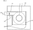
- FIG. 2 is a top plan view when viewed from the top side based on line A-A of FIG. 1 .
- the preprocessing apparatus according to the present invention includes an approximately cyclone main body 100, a cooling means, a heating means, a block 40 made of a thermally conductive material such as aluminum or copper, and a protection box 60.
- the cyclone main body 100 includes: a cylindrical portion 1 which has therein a space portion and disposed vertically; a conical portion 4 which communicate with the cylindrical portion 1 and has a structure, with a wide upper side and a narrow lower side, in which an upper portion has the same diameter as the cylindrical portion 1 so that the upper portion is connected to the cylindrical portion 1, and a diameter is gradually decreased toward a lower portion; a combustion gas inlet pipe 2 which is provided at one side of the cylindrical portion 1 and through the combustion gas including air pollutants to be measured is introduced; and a combustion gas discharge pipe 3 which is positioned at an upper side of a center of the cylindrical portion 1 and guides the preprocessed combustion gas to a pollutant analysis device at a rear end.
- a discharge port 8 is provided at a lower end of the conical portion 4 having the structure with the wide upper side and the narrow lower side, such that moisture and particles contained in the combustion gas to be described below are discharged.
- One of the main features of the present invention is that in the preprocessing apparatus according to the present invention, a cooling means and a heating means are provided in the combustion gas inlet pipe 2 and cooling means are provided in the cylindrical portion 1 and the conical portion 4 in order to remove moisture and particles contained in the combustion gas introduced into the cyclone main body 100.
- a first cooling Peltier element 21 is provided at one side of the combustion gas inlet pipe 2, and a heating Peltier element 31 is formed at the other side of the combustion gas inlet pipe 2.
- the reason why both of the first cooling Peltier element 21 and the heating Peltier element 31 are formed together on the combustion gas inlet pipe 2 is to maintain a temperature of the combustion gas introduced into the inlet pipe 2 within a predetermined range. That is, the reason is that moisture may be condensed if a temperature of the combustion gas is too low, and it is difficult to sufficiently expect the Mpemba effect if a temperature of the combustion gas is too high.
- the Mpemba effect means a phenomenon in which high-temperature water is more quickly frozen than low-temperature water in the same condition, and when water molecules are moved to be close to each other, the water molecules attract one another due to a hydrogen bond between the water molecules, and in this case, a covalent bond between a hydrogen atom and an oxygen atom is lengthened, such that energy is accumulated.
- the hydrogen bond is lengthened and density of water is decreased, and in this case, the covalent bond is decreased again, thereby releasing the accumulated energy. That is, the hot water with a large amount of accumulated energy is quickly frozen because the water more quickly releases energy when the water is cooled.
- second cooling Peltier elements 22 are provided at an outer circumferential edge of the cylindrical portion 1 and the conical portion 4, thereby decreasing a temperature of the introduced combustion gas to -20 ⁇ 10°C. Therefore, the moisture contained in the introduced combustion gas is crystallized by being cooled, and moisture crystals may serve to capture some particles contained in the combustion gas.
- the cooling means and the heating means are not particularly limited as long as the cooling means and the heating means are a cooling means (e.g., a cooler) and a heating means (e.g., an electric heater) that may achieve the same function and the same operational effect, but preferably, the cooling means and the heating means may be the first and second cooling Peltier elements 21 and 22 and the heating Peltier element 31 that use the Peltier effect.
- a cooling means e.g., a cooler
- a heating means e.g., an electric heater
- the first and second cooling Peltier elements 21 and 22 and the heating Peltier element 31 are devices for cooling or heating a particular local portion by using the Peltier effect, and use a thermoelectric refrigeration principle, that is, a kind of heat pumping phenomenon in which when a circuit is made by joining both ends of two different metal wires and direct current is applied to the circuit, heat is absorbed at one joint portion, and heat is generated at the other joint portion, and the heat absorption and the heat generation occur on the contrary when the direction of electric current is reversed. Therefore, the first and second cooling Peltier elements 21 and 22 and the heating Peltier element 31 using the principle are advantageous in accurately maintaining a temperature of a particular position to a desired temperature.
- the block 40 which is made of aluminum or copper having excellent thermal conductivity and low specific gravity, is disposed at the outer circumferential edges of the cylindrical portion 1 and the conical portion 4, and the block 40 made of aluminum or copper may be designed to be surrounded by the second cooling Peltier elements 22.
- an inner surface of the block 40 made of aluminum or copper has a shape corresponding to the cylindrical portion 1 and the conical portion 4, but an outer surface of the block 40 has a rectangular parallelepiped shape.
- the second cooling Peltier elements 22 are provided on the outer surface of the block 40 made of aluminum or copper which has a rectangular parallelepiped shape, and as a result, it is possible to easily attach, detach, and repair the second cooling Peltier elements 22.
- the preprocessing apparatus may further include the protection box 60 that accommodates the cyclone main body 100, the cooling means, and the heating means.
- the protection box 60 serves to protect the cyclone main body 100, the cooling means, and the heating means from external impact, and a space portion between the protection box 60 and the cyclone main body 100 is filled with a fiberglass layer 50 with an excellent thermal insulation effect. Therefore, it is possible to not only maintain a temperature of the conical portion 4 to -20 ⁇ 10°C by the second cooling Peltier elements 22, and but also prevent heat exchange with the outside, thereby efficiently managing energy.
- an inflow gas temperature sensor 5 is provided at one side of the inlet pipe 2 in order to measure a temperature of combustion gas including air pollutants, and a conical portion temperature sensor 6 is further provided to measure a temperature of the conical portion 4.
- the inflow gas temperature sensor 5 and the conical portion temperature sensor 6 serve to maintain a temperature of the introduced gas and a temperature of gas in the conical portion 4 to a desired range, thereby maximizing an effect of removing moisture and particles contained in combustion gas.
- a humidity sensor 7 may be provided at one side of the inlet pipe 2 in order to recognize humidity of the combustion gas containing air pollutants.
- the humidity sensor 7 decreases a flow rate of combustion gas if humidity of the introduced combustion gas is equal to or higher than a predetermined reference value, and increases a flow rate of combustion gas if humidity is equal to or lower than the predetermined reference value, and as a result, it is possible to allow moisture crystals to be uniformly formed on an inner wall surface of the cyclone main body by increasing and decreasing a flow rate of combustion gas in response to humidity of the introduced combustion gas.
- the preprocessing apparatus may further include a controller 9 capable of controlling and adjusting the temperature sensors 5 and 6, the humidity sensor 7, the cooling means, the heating means, and the like.
- the controller 9 may be a microcomputer, a CPU, or the like.
- the preprocessing method includes: introducing combustion gas, which needs to be preprocessed, into the cyclone main body 100 (S100); crystallizing moisture contained in the combustion gas by cooling the moisture by a cooling means and attaching some particulate matters to crystallized moisture particles (S120); attaching or settling the crystallized moisture particles and the particulate matters onto the cyclone main body 100 and discharging the combustion gas from which the moisture is removed (S140); introducing heated gas into the cyclone main body 100 and dissolving the crystallized moisture particles (S160); and discharging the dissolved moisture and the particulate matters to the outside (S180).
- the combustion gas is introduced into the combustion gas inlet pipe 2 provided at one side of the cylindrical portion 1 that constitutes the cyclone main body 100.
- a temperature of the combustion gas being introduced may be maintained at 70 ⁇ 10°C. That is, the reason is that moisture may be condensed if a temperature of the combustion gas is too low, and it is difficult to sufficiently expect the Mpemba effect if a temperature of the combustion gas is too high.
- the adjustment of the temperature of the combustion gas may be implemented by the first cooling Peltier element 21 disposed at one side of the inlet pipe 2 and the heating Peltier element 31 disposed at the other side.
- the introduced combustion gas is cooled by using the cooling means provided at the outer circumferential edge of the cylindrical portion 1 and the outer circumferential edge of the conical portion 4 at the lower side of the cylindrical portion 1.
- a cooling temperature by the cooling member 20 may be maintained at -20 ⁇ 10°C, and within the temperature range, the moisture in a vaporized state is crystallized, flows along with a flow of gas in the cyclone, and then is attached to the inner wall surface of the cylindrical portion 1 or the inner wall surface of the conical portion 4.
- some particulate matters are attached to moisture crystals.
- the moisture crystals or the particulate matters are not attached to the inner wall surface of the cylindrical portion 1 or the inner wall surface of the conical portion 4, the moisture crystals or the particulate matters, which are not attached to the inner wall surface of the cylindrical portion 1 or the inner wall surface of the conical portion 4, may be removed through the discharge port 8 provided at the lower side of the conical portion 4 because of the properties of the cyclone device that makes a swirling flow of a fluid, applies centrifugal force to particles contained in the fluid, and then separates and captures the particles from the liquid.
- warm gas may be supplied in a reverse direction through the combustion gas inlet pipe 2.
- the cooling means and the heating means are not particularly limited as long as the cooling means and the heating means are a cooling means and a heating means that may achieve the same function and the same operational effect, but preferably, the cooling means and the heating means may be the first and second cooling Peltier elements 21 and 22 and the heating Peltier element 31 that use the Peltier effect.
- the present invention may provide the preprocessing apparatus and the preprocessing method for measuring and analyzing air pollution, which are capable of removing particulate matters as well as moisture contained in combustion gas by cooling the combustion gas introduced into the cyclone main body.
- FIG. 6 is a cross-sectional front view of a preprocessing apparatus according to a second exemplary embodiment of the present invention
- FIG. 7 is a cross-sectional view taken along line B-B of FIG. 6
- FIG. 8 is a cross-sectional view taken along line C-C of FIG. 6
- FIG. 9 is a side view of a three-way valve 620 illustrated in FIG. 6
- FIG. 10 is an exploded perspective view of the preprocessing apparatus according to the second exemplary embodiment of the present invention
- FIG. 11 is an assembled view of the exploded perspective view illustrated in FIG. 10
- FIG. 12 is an enlarged view of a socket unit and a hood unit of the preprocessing apparatus according to the second exemplary embodiment of the present invention.
- the preprocessing apparatus when describing the preprocessing apparatus according to the second exemplary embodiment of the present invention, includes a combustion gas distribution unit 115, a cooling and heating block 200, a cooling block 300, a bundle of pipes 400, a socket unit 500, a hood 600, and a combustion gas inlet pipe 700.
- the combustion gas distribution unit 115 has a vacant cylindrical shape, a first opening portion 110 into which the combustion gas inlet pipe 700 to be described below is inserted and mounted is formed in an upper portion of the combustion gas distribution unit 115, and a plurality of second opening portions 120, which has the number and a size corresponding to the number of pipes and the size of the bundle of pipes 400, is provided in a lower surface of the combustion gas distribution unit 115 so that the bundle of pipes 400 to be described below may be inserted and mounted into the plurality of second opening portions 120.
- combustion gas conveyed to the combustion gas inlet pipe 700 is supplied to the combustion gas distribution unit 115, and then uniformly distributed into the bundle of pipes 400 inserted into the combustion gas distribution unit 115, such that the combustion gas flows to the cooling and heating block 200 and the cooling block 300 which will be described below.
- the cooling and heating block 200 is positioned at a bottom side of the combustion gas distribution unit 115, a plurality of elongated cylindrical spaces is formed in the cooling and heating block 200, and heating members and cooling members capable of performing heating or cooling are added to the outside of the cooling and heating block 200.
- a cooling and heating block temperature sensor 230 is provided inside the bundle of pipes 400 in order to measure a temperature of the combustion gas in the bundle of pipes 400 being in contact with the cooling and heating block 200.
- third cooling Peltier elements 210 which are the cooling members, are provided on two opposite outer surfaces of the cooling and heating block 200, and second heating Peltier elements 220, which are the heating members, are provided on the remaining two surfaces to which the third cooling Peltier elements 210 are not attached.
- the reason why the third cooling Peltier element 210 and the second heating Peltier element 220 are provided together as described above is to operate the second heating Peltier element 220 to heat the combustion gas when a temperature of the combustion gas in the bundle of pipes 400 being in contact with the cooling and heating block 200 is lower than a predetermined temperature, and to operate the third cooling Peltier element 210 to lower a temperature of the combustion gas when the temperature of the combustion gas is higher than the predetermined temperature on the contrary, and as a result, it is possible to adjust the temperature of the combustion gas within a predetermined range.
- a cooling function is performed when a temperature of the introduced combustion gas is equal to or higher than 80°C
- a heating function is performed when a temperature of inflow gas is equal to or lower than 60°C.
- the cooling member and the heating member are described as being the cooling Peltier element and the heating Peltier element that use the Peltier effect, but the cooling member and the heating member are not particularly limited as long as the cooling or heating member is a cooling or heating means capable of achieving the same function and the same operational effect.
- the cooling block 300 has the same shape and the same structure as the cooling and heating block 200, but only a difference between the cooling block 300 and the cooling and heating block 200 is that only fourth cooling Peltier elements 310, which are the cooling members, are provided on an outer circumferential surface of the cooling block 300.
- the cooling block 300 only serves to perform a function of cooling the combustion gas in the bundle of pipes 400 being in contact with the cooling block 300 within a predetermined temperature range, and a cooling block temperature sensor 320 for measuring a temperature of the combustion gas is provided inside the bundle of pipes 400 being in contact with the cooling block 300.
- the reason why the cooling and heating block 200 and the cooling block 310 are separately provided is to quickly crystallize moisture contained in the combustion gas by using the Mpemba effect.
- the combustion gas is heated by maintaining a high-temperature condition in the cooling and heating block 200, and the combustion gas is cooled by the cooling block 300 to the extent that the moisture contained in the combustion gas may be crystallized, thereby removing the moisture contained in the combustion gas.
- the cooling and heating block 200 and the cooling block 300 may be made of a material such as aluminum or copper with excellent thermal conductivity and low specific gravity in order to effectively receive and transfer heat from/to the heating member and the cooling member being in contact with the cooling and heating block 200 and the cooling member being in contact with the cooling block 300, and the cooling and heating block 200 and the cooling block 300 may have a rectangular parallelepiped shape in consideration of easy of attachment, detachment, and repair of the heating member and the cooling member.
- the bundle of pipes 400 serves to allow the combustion gas distributed from the combustion gas distribution unit 115 to flow therethrough, and performs a function of crystallizing moisture in the combustion gas based on the Mpemba effect, and removing the crystallized particles.
- the bundle of pipes 400 is an assembly of a plurality of pipes, and the bundle of pipes 400 is inserted into cylindrical portions 240 and 330 of the cooling and heating block 200 and the cooling block 300.
- upper end portions of the pipes are inserted into the second opening portions 120 of the combustion gas distribution unit 115 such that the combustion gas is introduced into the pipes, and lower end portions of the pipes are coupled to the socket unit 500 to be described below.
- the number of pipes of the bundle of pipes 400 are not limited and may be determined in consideration of a flow rate of the introduced combustion gas, a diameter of the pipe, a length of the pipe, and the like, and the pipe may not only be made of aluminum or copper with excellent thermal conductivity, but also be made of quartz or the like with low reactivity with the gas to be measured.
- the socket unit 500 accommodates the lower end portions of the bundle of pipes 400 which protrude to the outside of the cooling block 300, and the socket unit 500 has a sealed structure coupled to the hood 600.
- a sealed structure is required so that the entire amount of combustion gas may be conveyed to a measurement device via the bundle of pipes 400, and the socket unit 500 performs a sealing function by connecting the hood 600 and the bundle of pipes 400.
- a ' ⁇ '-shaped branch pipe 610 and a three-way valve 620 are installed on the hood 600 connected to the socket unit 500 in order to change a flow of gas.
- opening and closing directions of the three-way valve 620 are adjusted so that the combustion gas communicates with the gas discharge port 630 when introducing the combustion gas, from which moisture is removed, into the measurement device, and the combustion gas communicates with a liquid discharge port 640 when removing moisture crystals attached in the bundle of pipes 400.
- high-temperature gas may be injected into the bundle of pipes 400 or gas heated to a predetermined temperature by the cooling and heating block 200 may be used.
- a second humidity sensor 130 is further provided in an internal space of the combustion gas distribution unit 115 in order to recognize humidity of the combustion gas introduced into the combustion gas distribution unit 115. That is, the second humidity sensor 130 decreases a flow rate of combustion gas if humidity of the introduced combustion gas is equal to or higher than a predetermined reference value, and increases a flow rate of combustion gas if humidity is equal to or lower than the predetermined reference value, and as a result, it is possible to allow moisture crystals to be uniformly formed on an inner wall surface of the bundle of pipes by increasing and decreasing a flow rate of combustion gas in response to humidity of the introduced combustion gas.
- the second exemplary embodiment of the present invention is related to the preprocessing apparatus using the Mpemba effect, it is very important to control the combustion gas flowing in the bundle of pipes 400 within a predetermined range, and the bundle of pipes 400 needs to be protected from external impact in order to prevent a leak of combustion gas. Therefore, a second protection box 800 is installed to protect the combustion gas distribution unit 115, the cooling and heating block 200, the cooling block 300, and the hood 600 from external impact, and a second fiberglass layer 900, which has an excellent thermal insulation effect, is installed in the second protection box 800 in order to maximally inhibit heat transfer to the outside.
- the preprocessing method includes: a first step of introducing combustion gas into the combustion gas inlet pipe 700 (S200); a second step of distributing the introduced combustion gas into the bundle of pipes 400 (S210); a third step of cooling the distributed gas and crystallizing moisture contained in the combustion gas (S220); a fourth step of attaching the crystallized moisture particles to inner wall surfaces of the bundle of pipes 400 (S230); a fifth step of introducing heated gas and dissolving the crystallized moisture particles attached to the inner wall surfaces of the bundle of pipes 400 (S240); and a sixth step of discharging the dissolved moisture to the outside (S250).
- combustion gas to be measured is introduced into the combustion gas inlet pipe 700 in order to remove moisture contained in the combustion gas which acts as an interfering substance when measuring and analyzing air pollution.
- the combustion gas flows by being uniformly distributed into the bundle of pipes 400 made by assembling the plurality of pipes which is inserted and mounted into the cylindrical portions of the cooling and heating block 200 and the cooling block 300 and communicates with the combustion gas distribution unit 115.
- the cooling member and the heating member provided on the outer surface of the cooling and heating block 200 operate so that a temperature of the combustion gas is adjusted within a predetermined range, and then the cooling member provided outside the cooling block 300 operates to cool the combustion gas.
- the cooling member and the heating member are variably operated so that a temperature of the combustion gas introduced into the cooling and heating block 200 is maintained at 70 ⁇ 10°C, and a temperature of the combustion gas in the cooling block 300 is maintained at -20 ⁇ 10°C.
- moisture crystals are then formed while the moisture heated by the cooling and heating block 200 based on the Mpemba effect passes through the cooling block 300, and the moisture crystals are attached to the inner wall surfaces of the bundle of pipes 400, such that the moisture in the combustion gas is removed.
- the moisture crystals which are formed while the moisture passes through the cooling block 300, may be formed while capturing some particles contained in the combustion gas, and particles may be captured by the moisture crystals attached to the wall surfaces, such that the removal of some particles contained in the combustion gas may be expected.
- the moisture crystals which are produced through the aforementioned process, are continuously attached to the inner wall surfaces of the bundle of pipes 400, diameters of the bundle of pipes 400 are decreased, and as a result, pressure applied to the combustion gas inlet pipe 700 may be increased or cooling efficiency of the cooling block 300 may deteriorate. Therefore, it is necessary to remove the moisture crystals attached in the bundle of pipes 400.
- the removal of the moisture crystals may be achieved by injecting high-temperature gas into the bundle of pipes 400 after switching the three-way valve 620 or injecting gas heated to a predetermined temperature by the cooling and heating block 200.
- the present invention may provide the preprocessing apparatus and the preprocessing method for measuring and analyzing air pollution, in which the cooling member or the cooling and heating members are provided outside the cooling and heating block 200 and the cooling block 300, thereby removing moisture contained in the combustion gas by quickly decreasing a temperature of the combustion gas.
Landscapes
- Life Sciences & Earth Sciences (AREA)
- Health & Medical Sciences (AREA)
- General Health & Medical Sciences (AREA)
- Chemical & Material Sciences (AREA)
- Analytical Chemistry (AREA)
- Biochemistry (AREA)
- Physics & Mathematics (AREA)
- General Physics & Mathematics (AREA)
- Immunology (AREA)
- Pathology (AREA)
- Engineering & Computer Science (AREA)
- Biomedical Technology (AREA)
- Molecular Biology (AREA)
- Sampling And Sample Adjustment (AREA)
Applications Claiming Priority (3)
| Application Number | Priority Date | Filing Date | Title |
|---|---|---|---|
| KR1020150062008A KR101654193B1 (ko) | 2015-04-30 | 2015-04-30 | 대기오염 측정 분석을 위한 음페바 효과를 이용한 전처리 장치 및 방법 |
| KR1020150062003A KR101654178B1 (ko) | 2015-04-30 | 2015-04-30 | 대기오염 측정 분석을 위한 전처리 장치 및 방법 |
| PCT/KR2016/001978 WO2016175440A1 (ko) | 2015-04-30 | 2016-02-29 | 대기오염 측정 분석을 위한 전처리 장치 및 방법 |
Publications (3)
| Publication Number | Publication Date |
|---|---|
| EP3290901A1 true EP3290901A1 (de) | 2018-03-07 |
| EP3290901A4 EP3290901A4 (de) | 2019-01-02 |
| EP3290901B1 EP3290901B1 (de) | 2019-12-18 |
Family
ID=57198886
Family Applications (1)
| Application Number | Title | Priority Date | Filing Date |
|---|---|---|---|
| EP16786627.6A Active EP3290901B1 (de) | 2015-04-30 | 2016-02-29 | Vorbehandlungsvorrichtung und verfahren zur messung und analyse der luftverschmutzung |
Country Status (5)
| Country | Link |
|---|---|
| US (1) | US10578520B2 (de) |
| EP (1) | EP3290901B1 (de) |
| JP (1) | JP6469312B2 (de) |
| CN (1) | CN107810402B (de) |
| WO (1) | WO2016175440A1 (de) |
Cited By (1)
| Publication number | Priority date | Publication date | Assignee | Title |
|---|---|---|---|---|
| EP3355046A4 (de) * | 2015-09-24 | 2019-05-22 | Konkuk University Industrial Cooperation Corp. | Vorrichtung und verfahren zur entfernung von in einer gasphasensubstanz enthaltenem wasser durch phasenumwandlung von wasser in einer frostphase |
Families Citing this family (5)
| Publication number | Priority date | Publication date | Assignee | Title |
|---|---|---|---|---|
| US11692913B2 (en) * | 2016-02-11 | 2023-07-04 | Oizom Instruments Pvt. Ltd. | Air constituent measurement system, method and apparatus |
| WO2019207966A1 (ja) * | 2018-04-24 | 2019-10-31 | パナソニックIpマネジメント株式会社 | 検出装置及び検出方法 |
| DE102019120699A1 (de) * | 2019-07-31 | 2021-02-04 | Wagner Group Gmbh | Gasmessvorrichtung mit Heizeinrichtung |
| DE102019215596A1 (de) * | 2019-10-11 | 2020-12-03 | Vitesco Technologies GmbH | Brennstoffzellenvorrichtung mit Zyklonabscheider und Kühleinrichtung für ein Kraftfahrzeug |
| KR102260692B1 (ko) * | 2021-01-26 | 2021-06-07 | 한국표준과학연구원 | 굴뚝 배출 미세먼지 실시간 측정 장치 |
Family Cites Families (19)
| Publication number | Priority date | Publication date | Assignee | Title |
|---|---|---|---|---|
| JPS6110722Y2 (de) * | 1979-11-28 | 1986-04-05 | ||
| JPH0429395Y2 (de) * | 1985-02-07 | 1992-07-16 | ||
| JP2507642B2 (ja) * | 1989-12-25 | 1996-06-12 | 株式会社東芝 | 水分補集装置 |
| JPH09215906A (ja) * | 1996-02-09 | 1997-08-19 | Kyushu Hitachi Maxell Ltd | 除湿装置 |
| JP3029706U (ja) * | 1996-04-02 | 1996-10-11 | 春男 上原 | 凝縮装置 |
| JP3135519B2 (ja) * | 1997-05-23 | 2001-02-19 | 泰世司 曽師 | 排気ガス処理設備 |
| JP2000317349A (ja) * | 1999-05-13 | 2000-11-21 | Sharp Corp | サイクロン式集塵器およびこの集塵器を用いたエアサイクルシステム |
| GB9911336D0 (en) * | 1999-05-15 | 1999-07-14 | Graseby Dynamics Ltd | Separation and collection of analyte materials |
| JP3593085B2 (ja) * | 2001-10-22 | 2004-11-24 | 三菱重工業株式会社 | 試料濃縮装置及び有機微量成分の検出装置 |
| JP2005131509A (ja) * | 2003-10-29 | 2005-05-26 | Unisem Co Ltd | 廃ガス処理処置及び廃ガス処理方法 |
| KR100631477B1 (ko) | 2004-11-03 | 2006-10-09 | 건국대학교 산학협력단 | 대기오염 분석을 위한 수분 전처리 수단이 구비된 시료포집장치 |
| KR100823947B1 (ko) | 2007-07-18 | 2008-04-22 | 구성테크닉스 주식회사 | 유량 조절이 가능한 습식 먼지 측정 시스템 |
| JP5012588B2 (ja) * | 2008-03-07 | 2012-08-29 | 日産自動車株式会社 | 廃熱回収装置 |
| JP5320001B2 (ja) * | 2008-09-26 | 2013-10-23 | オーム電機株式会社 | 電子除湿器 |
| US9028758B2 (en) * | 2009-12-24 | 2015-05-12 | Explodet Technologies Ltd. | Substance detector with cyclone |
| CN102032997B (zh) * | 2010-11-18 | 2012-08-22 | 安徽淮化股份有限公司 | 一种流化床反应器的气液固三相同时取样装置 |
| US20130174577A1 (en) * | 2012-01-10 | 2013-07-11 | Spring (U.S.A.) Corporation | Heating and Cooling Unit with Semiconductor Device and Heat Pipe |
| CN103149271A (zh) * | 2013-03-18 | 2013-06-12 | 中国环境科学研究院 | 一种同时测定燃煤烟气中不同形态重金属的方法 |
| AT515081B1 (de) * | 2014-02-20 | 2015-06-15 | Anton Paar Provetec Gmbh | Verfahren zur Einstellung der Temperatur und Temperierbehälter |
-
2016
- 2016-02-29 US US15/570,547 patent/US10578520B2/en active Active
- 2016-02-29 WO PCT/KR2016/001978 patent/WO2016175440A1/ko not_active Ceased
- 2016-02-29 CN CN201680025008.0A patent/CN107810402B/zh active Active
- 2016-02-29 JP JP2018509715A patent/JP6469312B2/ja not_active Expired - Fee Related
- 2016-02-29 EP EP16786627.6A patent/EP3290901B1/de active Active
Cited By (1)
| Publication number | Priority date | Publication date | Assignee | Title |
|---|---|---|---|---|
| EP3355046A4 (de) * | 2015-09-24 | 2019-05-22 | Konkuk University Industrial Cooperation Corp. | Vorrichtung und verfahren zur entfernung von in einer gasphasensubstanz enthaltenem wasser durch phasenumwandlung von wasser in einer frostphase |
Also Published As
| Publication number | Publication date |
|---|---|
| JP2018518687A (ja) | 2018-07-12 |
| EP3290901B1 (de) | 2019-12-18 |
| US20180143105A1 (en) | 2018-05-24 |
| CN107810402B (zh) | 2020-09-15 |
| JP6469312B2 (ja) | 2019-02-13 |
| CN107810402A (zh) | 2018-03-16 |
| US10578520B2 (en) | 2020-03-03 |
| WO2016175440A1 (ko) | 2016-11-03 |
| EP3290901A4 (de) | 2019-01-02 |
Similar Documents
| Publication | Publication Date | Title |
|---|---|---|
| EP3290901B1 (de) | Vorbehandlungsvorrichtung und verfahren zur messung und analyse der luftverschmutzung | |
| KR101654193B1 (ko) | 대기오염 측정 분석을 위한 음페바 효과를 이용한 전처리 장치 및 방법 | |
| KR101654178B1 (ko) | 대기오염 측정 분석을 위한 전처리 장치 및 방법 | |
| KR101976934B1 (ko) | 대기오염 측정 분석을 위한 수분 전처리 장치 및 수분 배출방법 | |
| US20040200229A1 (en) | Refrigeration system utilizing incomplete evaporation of refrigerant in evaporator | |
| KR101508972B1 (ko) | 열전도성 플라스틱 냉각관을 구비한 스크러버용 제습장치 | |
| KR102184500B1 (ko) | 연속적인 미세먼지 분석을 위한 수직형 듀얼 디졸베이터 및 그 동작방법 | |
| KR101915380B1 (ko) | 대기오염 측정 분석용 수분 전처리 장치를 위한 성에 배출장치 | |
| CN109692544B (zh) | 气液分离器及大气采样设备 | |
| JP3213883B2 (ja) | 凝縮物分離装置 | |
| US11067483B2 (en) | Hybrid cooler/dryer and method therefor | |
| KR101469726B1 (ko) | 스크러버용 제습장치 | |
| KR101441067B1 (ko) | 드랍링이 설치된 스크러버 장치 | |
| CN103148648B (zh) | 空调用紫铜分液器及空调 | |
| CN205449640U (zh) | 吸附热解吸装置 | |
| KR101441066B1 (ko) | 스크러버 장치 | |
| ES2211242B1 (es) | Detector de defectos de estanqueidad, procedimientos, utilizacion e intercambiadores de calor correspondientes. | |
| KR101459000B1 (ko) | 스크러버 장치 | |
| JP2003194680A (ja) | ガス分析用除湿器 | |
| KR101928162B1 (ko) | 대기오염 측정 분석을 위한 수분 전처리 장치의 배출장치 및 배출방법 | |
| EP3355046B1 (de) | Vorrichtung und verfahren zur entfernung von in einer gasphasensubstanz enthaltenem wasser durch phasenumwandlung von wasser in einer frostphase | |
| CN204882200U (zh) | 样气冷凝装置 | |
| KR102582209B1 (ko) | 수분전처리 장치용 고효율 라디에이터 장치 | |
| US20240344718A1 (en) | Gas humidity reduction apparatus and method of using the same | |
| RU2234361C1 (ru) | Термоэлектрический мембранный газоразделительный элемент |
Legal Events
| Date | Code | Title | Description |
|---|---|---|---|
| STAA | Information on the status of an ep patent application or granted ep patent |
Free format text: STATUS: THE INTERNATIONAL PUBLICATION HAS BEEN MADE |
|
| PUAI | Public reference made under article 153(3) epc to a published international application that has entered the european phase |
Free format text: ORIGINAL CODE: 0009012 |
|
| STAA | Information on the status of an ep patent application or granted ep patent |
Free format text: STATUS: REQUEST FOR EXAMINATION WAS MADE |
|
| 17P | Request for examination filed |
Effective date: 20171130 |
|
| AK | Designated contracting states |
Kind code of ref document: A1 Designated state(s): AL AT BE BG CH CY CZ DE DK EE ES FI FR GB GR HR HU IE IS IT LI LT LU LV MC MK MT NL NO PL PT RO RS SE SI SK SM TR |
|
| AX | Request for extension of the european patent |
Extension state: BA ME |
|
| DAV | Request for validation of the european patent (deleted) | ||
| DAX | Request for extension of the european patent (deleted) | ||
| A4 | Supplementary search report drawn up and despatched |
Effective date: 20181205 |
|
| RIC1 | Information provided on ipc code assigned before grant |
Ipc: G01N 1/44 20060101ALI20181129BHEP Ipc: G01N 1/22 20060101AFI20181129BHEP Ipc: G01N 1/42 20060101ALI20181129BHEP |
|
| GRAP | Despatch of communication of intention to grant a patent |
Free format text: ORIGINAL CODE: EPIDOSNIGR1 |
|
| STAA | Information on the status of an ep patent application or granted ep patent |
Free format text: STATUS: GRANT OF PATENT IS INTENDED |
|
| INTG | Intention to grant announced |
Effective date: 20190816 |
|
| GRAS | Grant fee paid |
Free format text: ORIGINAL CODE: EPIDOSNIGR3 |
|
| GRAA | (expected) grant |
Free format text: ORIGINAL CODE: 0009210 |
|
| STAA | Information on the status of an ep patent application or granted ep patent |
Free format text: STATUS: THE PATENT HAS BEEN GRANTED |
|
| AK | Designated contracting states |
Kind code of ref document: B1 Designated state(s): AL AT BE BG CH CY CZ DE DK EE ES FI FR GB GR HR HU IE IS IT LI LT LU LV MC MK MT NL NO PL PT RO RS SE SI SK SM TR |
|
| REG | Reference to a national code |
Ref country code: CH Ref legal event code: EP |
|
| REG | Reference to a national code |
Ref country code: IE Ref legal event code: FG4D |
|
| REG | Reference to a national code |
Ref country code: DE Ref legal event code: R096 Ref document number: 602016026538 Country of ref document: DE |
|
| REG | Reference to a national code |
Ref country code: AT Ref legal event code: REF Ref document number: 1215141 Country of ref document: AT Kind code of ref document: T Effective date: 20200115 |
|
| REG | Reference to a national code |
Ref country code: NL Ref legal event code: MP Effective date: 20191218 |
|
| PG25 | Lapsed in a contracting state [announced via postgrant information from national office to epo] |
Ref country code: SE Free format text: LAPSE BECAUSE OF FAILURE TO SUBMIT A TRANSLATION OF THE DESCRIPTION OR TO PAY THE FEE WITHIN THE PRESCRIBED TIME-LIMIT Effective date: 20191218 Ref country code: LV Free format text: LAPSE BECAUSE OF FAILURE TO SUBMIT A TRANSLATION OF THE DESCRIPTION OR TO PAY THE FEE WITHIN THE PRESCRIBED TIME-LIMIT Effective date: 20191218 Ref country code: GR Free format text: LAPSE BECAUSE OF FAILURE TO SUBMIT A TRANSLATION OF THE DESCRIPTION OR TO PAY THE FEE WITHIN THE PRESCRIBED TIME-LIMIT Effective date: 20200319 Ref country code: LT Free format text: LAPSE BECAUSE OF FAILURE TO SUBMIT A TRANSLATION OF THE DESCRIPTION OR TO PAY THE FEE WITHIN THE PRESCRIBED TIME-LIMIT Effective date: 20191218 Ref country code: NO Free format text: LAPSE BECAUSE OF FAILURE TO SUBMIT A TRANSLATION OF THE DESCRIPTION OR TO PAY THE FEE WITHIN THE PRESCRIBED TIME-LIMIT Effective date: 20200318 Ref country code: FI Free format text: LAPSE BECAUSE OF FAILURE TO SUBMIT A TRANSLATION OF THE DESCRIPTION OR TO PAY THE FEE WITHIN THE PRESCRIBED TIME-LIMIT Effective date: 20191218 Ref country code: BG Free format text: LAPSE BECAUSE OF FAILURE TO SUBMIT A TRANSLATION OF THE DESCRIPTION OR TO PAY THE FEE WITHIN THE PRESCRIBED TIME-LIMIT Effective date: 20200318 |
|
| PGFP | Annual fee paid to national office [announced via postgrant information from national office to epo] |
Ref country code: DE Payment date: 20200227 Year of fee payment: 5 Ref country code: GB Payment date: 20200227 Year of fee payment: 5 |
|
| REG | Reference to a national code |
Ref country code: LT Ref legal event code: MG4D |
|
| PG25 | Lapsed in a contracting state [announced via postgrant information from national office to epo] |
Ref country code: HR Free format text: LAPSE BECAUSE OF FAILURE TO SUBMIT A TRANSLATION OF THE DESCRIPTION OR TO PAY THE FEE WITHIN THE PRESCRIBED TIME-LIMIT Effective date: 20191218 Ref country code: RS Free format text: LAPSE BECAUSE OF FAILURE TO SUBMIT A TRANSLATION OF THE DESCRIPTION OR TO PAY THE FEE WITHIN THE PRESCRIBED TIME-LIMIT Effective date: 20191218 |
|
| PG25 | Lapsed in a contracting state [announced via postgrant information from national office to epo] |
Ref country code: AL Free format text: LAPSE BECAUSE OF FAILURE TO SUBMIT A TRANSLATION OF THE DESCRIPTION OR TO PAY THE FEE WITHIN THE PRESCRIBED TIME-LIMIT Effective date: 20191218 |
|
| PGFP | Annual fee paid to national office [announced via postgrant information from national office to epo] |
Ref country code: FR Payment date: 20200225 Year of fee payment: 5 |
|
| PG25 | Lapsed in a contracting state [announced via postgrant information from national office to epo] |
Ref country code: PT Free format text: LAPSE BECAUSE OF FAILURE TO SUBMIT A TRANSLATION OF THE DESCRIPTION OR TO PAY THE FEE WITHIN THE PRESCRIBED TIME-LIMIT Effective date: 20200513 Ref country code: CZ Free format text: LAPSE BECAUSE OF FAILURE TO SUBMIT A TRANSLATION OF THE DESCRIPTION OR TO PAY THE FEE WITHIN THE PRESCRIBED TIME-LIMIT Effective date: 20191218 Ref country code: NL Free format text: LAPSE BECAUSE OF FAILURE TO SUBMIT A TRANSLATION OF THE DESCRIPTION OR TO PAY THE FEE WITHIN THE PRESCRIBED TIME-LIMIT Effective date: 20191218 Ref country code: EE Free format text: LAPSE BECAUSE OF FAILURE TO SUBMIT A TRANSLATION OF THE DESCRIPTION OR TO PAY THE FEE WITHIN THE PRESCRIBED TIME-LIMIT Effective date: 20191218 Ref country code: RO Free format text: LAPSE BECAUSE OF FAILURE TO SUBMIT A TRANSLATION OF THE DESCRIPTION OR TO PAY THE FEE WITHIN THE PRESCRIBED TIME-LIMIT Effective date: 20191218 |
|
| PG25 | Lapsed in a contracting state [announced via postgrant information from national office to epo] |
Ref country code: IS Free format text: LAPSE BECAUSE OF FAILURE TO SUBMIT A TRANSLATION OF THE DESCRIPTION OR TO PAY THE FEE WITHIN THE PRESCRIBED TIME-LIMIT Effective date: 20200418 Ref country code: SK Free format text: LAPSE BECAUSE OF FAILURE TO SUBMIT A TRANSLATION OF THE DESCRIPTION OR TO PAY THE FEE WITHIN THE PRESCRIBED TIME-LIMIT Effective date: 20191218 Ref country code: SM Free format text: LAPSE BECAUSE OF FAILURE TO SUBMIT A TRANSLATION OF THE DESCRIPTION OR TO PAY THE FEE WITHIN THE PRESCRIBED TIME-LIMIT Effective date: 20191218 |
|
| REG | Reference to a national code |
Ref country code: DE Ref legal event code: R097 Ref document number: 602016026538 Country of ref document: DE |
|
| REG | Reference to a national code |
Ref country code: CH Ref legal event code: PL |
|
| REG | Reference to a national code |
Ref country code: AT Ref legal event code: MK05 Ref document number: 1215141 Country of ref document: AT Kind code of ref document: T Effective date: 20191218 |
|
| PLBE | No opposition filed within time limit |
Free format text: ORIGINAL CODE: 0009261 |
|
| STAA | Information on the status of an ep patent application or granted ep patent |
Free format text: STATUS: NO OPPOSITION FILED WITHIN TIME LIMIT |
|
| REG | Reference to a national code |
Ref country code: BE Ref legal event code: MM Effective date: 20200229 |
|
| PG25 | Lapsed in a contracting state [announced via postgrant information from national office to epo] |
Ref country code: LU Free format text: LAPSE BECAUSE OF NON-PAYMENT OF DUE FEES Effective date: 20200229 Ref country code: ES Free format text: LAPSE BECAUSE OF FAILURE TO SUBMIT A TRANSLATION OF THE DESCRIPTION OR TO PAY THE FEE WITHIN THE PRESCRIBED TIME-LIMIT Effective date: 20191218 Ref country code: MC Free format text: LAPSE BECAUSE OF FAILURE TO SUBMIT A TRANSLATION OF THE DESCRIPTION OR TO PAY THE FEE WITHIN THE PRESCRIBED TIME-LIMIT Effective date: 20191218 Ref country code: DK Free format text: LAPSE BECAUSE OF FAILURE TO SUBMIT A TRANSLATION OF THE DESCRIPTION OR TO PAY THE FEE WITHIN THE PRESCRIBED TIME-LIMIT Effective date: 20191218 |
|
| 26N | No opposition filed |
Effective date: 20200921 |
|
| PG25 | Lapsed in a contracting state [announced via postgrant information from national office to epo] |
Ref country code: SI Free format text: LAPSE BECAUSE OF FAILURE TO SUBMIT A TRANSLATION OF THE DESCRIPTION OR TO PAY THE FEE WITHIN THE PRESCRIBED TIME-LIMIT Effective date: 20191218 Ref country code: LI Free format text: LAPSE BECAUSE OF NON-PAYMENT OF DUE FEES Effective date: 20200229 Ref country code: CH Free format text: LAPSE BECAUSE OF NON-PAYMENT OF DUE FEES Effective date: 20200229 Ref country code: AT Free format text: LAPSE BECAUSE OF FAILURE TO SUBMIT A TRANSLATION OF THE DESCRIPTION OR TO PAY THE FEE WITHIN THE PRESCRIBED TIME-LIMIT Effective date: 20191218 |
|
| PG25 | Lapsed in a contracting state [announced via postgrant information from national office to epo] |
Ref country code: IE Free format text: LAPSE BECAUSE OF NON-PAYMENT OF DUE FEES Effective date: 20200229 Ref country code: IT Free format text: LAPSE BECAUSE OF FAILURE TO SUBMIT A TRANSLATION OF THE DESCRIPTION OR TO PAY THE FEE WITHIN THE PRESCRIBED TIME-LIMIT Effective date: 20191218 |
|
| PG25 | Lapsed in a contracting state [announced via postgrant information from national office to epo] |
Ref country code: PL Free format text: LAPSE BECAUSE OF FAILURE TO SUBMIT A TRANSLATION OF THE DESCRIPTION OR TO PAY THE FEE WITHIN THE PRESCRIBED TIME-LIMIT Effective date: 20191218 Ref country code: BE Free format text: LAPSE BECAUSE OF NON-PAYMENT OF DUE FEES Effective date: 20200229 |
|
| REG | Reference to a national code |
Ref country code: DE Ref legal event code: R119 Ref document number: 602016026538 Country of ref document: DE |
|
| GBPC | Gb: european patent ceased through non-payment of renewal fee |
Effective date: 20210228 |
|
| PG25 | Lapsed in a contracting state [announced via postgrant information from national office to epo] |
Ref country code: DE Free format text: LAPSE BECAUSE OF NON-PAYMENT OF DUE FEES Effective date: 20210901 Ref country code: FR Free format text: LAPSE BECAUSE OF NON-PAYMENT OF DUE FEES Effective date: 20210228 Ref country code: GB Free format text: LAPSE BECAUSE OF NON-PAYMENT OF DUE FEES Effective date: 20210228 |
|
| PG25 | Lapsed in a contracting state [announced via postgrant information from national office to epo] |
Ref country code: TR Free format text: LAPSE BECAUSE OF FAILURE TO SUBMIT A TRANSLATION OF THE DESCRIPTION OR TO PAY THE FEE WITHIN THE PRESCRIBED TIME-LIMIT Effective date: 20191218 Ref country code: MT Free format text: LAPSE BECAUSE OF FAILURE TO SUBMIT A TRANSLATION OF THE DESCRIPTION OR TO PAY THE FEE WITHIN THE PRESCRIBED TIME-LIMIT Effective date: 20191218 Ref country code: CY Free format text: LAPSE BECAUSE OF FAILURE TO SUBMIT A TRANSLATION OF THE DESCRIPTION OR TO PAY THE FEE WITHIN THE PRESCRIBED TIME-LIMIT Effective date: 20191218 |
|
| PG25 | Lapsed in a contracting state [announced via postgrant information from national office to epo] |
Ref country code: MK Free format text: LAPSE BECAUSE OF FAILURE TO SUBMIT A TRANSLATION OF THE DESCRIPTION OR TO PAY THE FEE WITHIN THE PRESCRIBED TIME-LIMIT Effective date: 20191218 |