EP3355046B1 - Vorrichtung und verfahren zur entfernung von in einer gasphasensubstanz enthaltenem wasser durch phasenumwandlung von wasser in einer frostphase - Google Patents
Vorrichtung und verfahren zur entfernung von in einer gasphasensubstanz enthaltenem wasser durch phasenumwandlung von wasser in einer frostphase Download PDFInfo
- Publication number
- EP3355046B1 EP3355046B1 EP16848738.7A EP16848738A EP3355046B1 EP 3355046 B1 EP3355046 B1 EP 3355046B1 EP 16848738 A EP16848738 A EP 16848738A EP 3355046 B1 EP3355046 B1 EP 3355046B1
- Authority
- EP
- European Patent Office
- Prior art keywords
- frost
- gas
- unit
- main body
- phase
- Prior art date
- Legal status (The legal status is an assumption and is not a legal conclusion. Google has not performed a legal analysis and makes no representation as to the accuracy of the status listed.)
- Active
Links
Images


Classifications
-
- B—PERFORMING OPERATIONS; TRANSPORTING
- B01—PHYSICAL OR CHEMICAL PROCESSES OR APPARATUS IN GENERAL
- B01D—SEPARATION
- B01D7/00—Sublimation
- B01D7/02—Crystallisation directly from the vapour phase
-
- G—PHYSICS
- G01—MEASURING; TESTING
- G01N—INVESTIGATING OR ANALYSING MATERIALS BY DETERMINING THEIR CHEMICAL OR PHYSICAL PROPERTIES
- G01N1/00—Sampling; Preparing specimens for investigation
- G01N1/02—Devices for withdrawing samples
- G01N1/22—Devices for withdrawing samples in the gaseous state
-
- B—PERFORMING OPERATIONS; TRANSPORTING
- B01—PHYSICAL OR CHEMICAL PROCESSES OR APPARATUS IN GENERAL
- B01D—SEPARATION
- B01D5/00—Condensation of vapours; Recovering volatile solvents by condensation
- B01D5/0033—Other features
- B01D5/0042—Thermo-electric condensing; using Peltier-effect
-
- B—PERFORMING OPERATIONS; TRANSPORTING
- B01—PHYSICAL OR CHEMICAL PROCESSES OR APPARATUS IN GENERAL
- B01D—SEPARATION
- B01D53/00—Separation of gases or vapours; Recovering vapours of volatile solvents from gases; Chemical or biological purification of waste gases, e.g. engine exhaust gases, smoke, fumes, flue gases, aerosols
- B01D53/26—Drying gases or vapours
- B01D53/265—Drying gases or vapours by refrigeration (condensation)
-
- B—PERFORMING OPERATIONS; TRANSPORTING
- B03—SEPARATION OF SOLID MATERIALS USING LIQUIDS OR USING PNEUMATIC TABLES OR JIGS; MAGNETIC OR ELECTROSTATIC SEPARATION OF SOLID MATERIALS FROM SOLID MATERIALS OR FLUIDS; SEPARATION BY HIGH-VOLTAGE ELECTRIC FIELDS
- B03C—MAGNETIC OR ELECTROSTATIC SEPARATION OF SOLID MATERIALS FROM SOLID MATERIALS OR FLUIDS; SEPARATION BY HIGH-VOLTAGE ELECTRIC FIELDS
- B03C3/00—Separating dispersed particles from gases or vapour, e.g. air, by electrostatic effect
- B03C3/02—Plant or installations having external electricity supply
- B03C3/16—Plant or installations having external electricity supply wet type
-
- C—CHEMISTRY; METALLURGY
- C02—TREATMENT OF WATER, WASTE WATER, SEWAGE, OR SLUDGE
- C02F—TREATMENT OF WATER, WASTE WATER, SEWAGE, OR SLUDGE
- C02F1/00—Treatment of water, waste water, or sewage
- C02F1/02—Treatment of water, waste water, or sewage by heating
- C02F1/04—Treatment of water, waste water, or sewage by heating by distillation or evaporation
- C02F1/048—Purification of waste water by evaporation
-
- F—MECHANICAL ENGINEERING; LIGHTING; HEATING; WEAPONS; BLASTING
- F25—REFRIGERATION OR COOLING; COMBINED HEATING AND REFRIGERATION SYSTEMS; HEAT PUMP SYSTEMS; MANUFACTURE OR STORAGE OF ICE; LIQUEFACTION SOLIDIFICATION OF GASES
- F25D—REFRIGERATORS; COLD ROOMS; ICE-BOXES; COOLING OR FREEZING APPARATUS NOT OTHERWISE PROVIDED FOR
- F25D17/00—Arrangements for circulating cooling fluids; Arrangements for circulating gas, e.g. air, within refrigerated spaces
- F25D17/04—Arrangements for circulating cooling fluids; Arrangements for circulating gas, e.g. air, within refrigerated spaces for circulating air, e.g. by convection
- F25D17/06—Arrangements for circulating cooling fluids; Arrangements for circulating gas, e.g. air, within refrigerated spaces for circulating air, e.g. by convection by forced circulation
-
- G—PHYSICS
- G01—MEASURING; TESTING
- G01N—INVESTIGATING OR ANALYSING MATERIALS BY DETERMINING THEIR CHEMICAL OR PHYSICAL PROPERTIES
- G01N1/00—Sampling; Preparing specimens for investigation
- G01N1/02—Devices for withdrawing samples
- G01N1/22—Devices for withdrawing samples in the gaseous state
- G01N1/2273—Atmospheric sampling
-
- B—PERFORMING OPERATIONS; TRANSPORTING
- B01—PHYSICAL OR CHEMICAL PROCESSES OR APPARATUS IN GENERAL
- B01D—SEPARATION
- B01D2257/00—Components to be removed
- B01D2257/30—Sulfur compounds
- B01D2257/302—Sulfur oxides
-
- B—PERFORMING OPERATIONS; TRANSPORTING
- B01—PHYSICAL OR CHEMICAL PROCESSES OR APPARATUS IN GENERAL
- B01D—SEPARATION
- B01D2257/00—Components to be removed
- B01D2257/40—Nitrogen compounds
- B01D2257/404—Nitrogen oxides other than dinitrogen oxide
-
- B—PERFORMING OPERATIONS; TRANSPORTING
- B01—PHYSICAL OR CHEMICAL PROCESSES OR APPARATUS IN GENERAL
- B01D—SEPARATION
- B01D2257/00—Components to be removed
- B01D2257/50—Carbon oxides
- B01D2257/502—Carbon monoxide
-
- B—PERFORMING OPERATIONS; TRANSPORTING
- B01—PHYSICAL OR CHEMICAL PROCESSES OR APPARATUS IN GENERAL
- B01D—SEPARATION
- B01D2257/00—Components to be removed
- B01D2257/50—Carbon oxides
- B01D2257/504—Carbon dioxide
-
- B—PERFORMING OPERATIONS; TRANSPORTING
- B01—PHYSICAL OR CHEMICAL PROCESSES OR APPARATUS IN GENERAL
- B01D—SEPARATION
- B01D2257/00—Components to be removed
- B01D2257/60—Heavy metals or heavy metal compounds
-
- B—PERFORMING OPERATIONS; TRANSPORTING
- B01—PHYSICAL OR CHEMICAL PROCESSES OR APPARATUS IN GENERAL
- B01D—SEPARATION
- B01D2257/00—Components to be removed
- B01D2257/70—Organic compounds not provided for in groups B01D2257/00 - B01D2257/602
- B01D2257/708—Volatile organic compounds V.O.C.'s
-
- B—PERFORMING OPERATIONS; TRANSPORTING
- B01—PHYSICAL OR CHEMICAL PROCESSES OR APPARATUS IN GENERAL
- B01D—SEPARATION
- B01D2257/00—Components to be removed
- B01D2257/80—Water
-
- B—PERFORMING OPERATIONS; TRANSPORTING
- B01—PHYSICAL OR CHEMICAL PROCESSES OR APPARATUS IN GENERAL
- B01D—SEPARATION
- B01D2257/00—Components to be removed
- B01D2257/90—Odorous compounds not provided for in groups B01D2257/00 - B01D2257/708
-
- B—PERFORMING OPERATIONS; TRANSPORTING
- B01—PHYSICAL OR CHEMICAL PROCESSES OR APPARATUS IN GENERAL
- B01D—SEPARATION
- B01D2258/00—Sources of waste gases
- B01D2258/06—Polluted air
-
- G—PHYSICS
- G01—MEASURING; TESTING
- G01N—INVESTIGATING OR ANALYSING MATERIALS BY DETERMINING THEIR CHEMICAL OR PHYSICAL PROPERTIES
- G01N1/00—Sampling; Preparing specimens for investigation
- G01N1/02—Devices for withdrawing samples
- G01N1/22—Devices for withdrawing samples in the gaseous state
- G01N2001/2282—Devices for withdrawing samples in the gaseous state with cooling means
-
- Y—GENERAL TAGGING OF NEW TECHNOLOGICAL DEVELOPMENTS; GENERAL TAGGING OF CROSS-SECTIONAL TECHNOLOGIES SPANNING OVER SEVERAL SECTIONS OF THE IPC; TECHNICAL SUBJECTS COVERED BY FORMER USPC CROSS-REFERENCE ART COLLECTIONS [XRACs] AND DIGESTS
- Y02—TECHNOLOGIES OR APPLICATIONS FOR MITIGATION OR ADAPTATION AGAINST CLIMATE CHANGE
- Y02P—CLIMATE CHANGE MITIGATION TECHNOLOGIES IN THE PRODUCTION OR PROCESSING OF GOODS
- Y02P70/00—Climate change mitigation technologies in the production process for final industrial or consumer products
- Y02P70/10—Greenhouse gas [GHG] capture, material saving, heat recovery or other energy efficient measures, e.g. motor control, characterised by manufacturing processes, e.g. for rolling metal or metal working
Definitions
- the present invention relates to an apparatus and a method of removing water contained in a gaseous material, and more particularly, to an apparatus and a method of removing water by cooling a gaseous material containing water to phase-change the water to a frost phase and separate the water so that a target gas in which water is not contained is obtained.
- a countermeasure against the environmental pollution problem may be broadly classified into a technology of suppressing emission of pollutants and a technology of removing emitted pollutants which are inevitably emitted.
- an apparatus of monitoring air pollutants caused from combustion of fossil fuel or various manufacturing processes in the environmental pollution generally uses a measurement method based on an optical device.
- the monitoring apparatus it is difficult for the monitoring apparatus to identify an exact name or concentration of the air pollutants contained in combusted gas due to moisture or particulate materials contained in a gaseous material to be measured.
- the pollutants need to be introduced into the measurement device after removing moisture or particulate materials which obstruct measurement or analysis in advance and thus a filter may be used as such a pre-treatment method.
- the filter removes not only the moisture and particulate materials, but also gaseous pollutants which need to be measured so that they should not be removed because the moisture or particulate materials which are removed through the filter form another filter media. Therefore, it is difficult to exactly identify the pollutants.
- Korean Unexamined Patent Application Publication No 2006-0039465 discloses a pretreatment apparatus of removing moisture which includes a glass tube and a Peltier trap for cooling and adhering moisture onto an inner periphery to remove the moisture, and a moisture pretreatment unit for analyzing air pollution which is heated and driven to remove moisture after completely collecting samples by a sampling unit.
- EP 3290901A1 relates to a preprocessing apparatus and a preprocessing method for analyzing air pollution, and more particularly, a preprocessing apparatus and a preprocessing method for measuring and analyzing air pollution, which are capable of effectively removing moisture and particulate matters to be measured and contained in combustion gas by adjusting a temperature of the combustion gas to a predetermined range, cooling the combustion gas, and thus inducing crystallization of moisture contained in the combustion gas.
- GB 2477293A discloses obtaining water from atmospheric air comprises cooling atmospheric air to produce water and separating the water from residual air by centrifugal force.
- US5119640A and JP2008279379A disclose an apparatus wherein frost is captured in a cooling unit and then removed by defrosting.
- US 2002000096A1 relates to the cryogenic removal of volatile compounds.
- moisture contained in the gas may be removed using the Peltier trap.
- the moisture contained in the contaminated gas is condensed on an inner periphery of a tube so that a diameter of a flow passage becomes narrower. Therefore, it is difficult to constantly maintain a flow rate of the gas flowing into the measurement device.
- the number of tubes needs to be increased to prevent such a clogging phenomenon and correspondingly the number of flow rate adjusting devices and Peltier traps needs to be increased, which causes a great economic loss.
- a first object to be achieved by the present invention is to provide an apparatus and a method of removing water by phase-changing water contained in a gaseous material to a frost phase which completely removes the water contained in the gaseous material which obstructs measurement or analysis, thereby ensuring reliability for a monitoring device of an air pollutant.
- a second object of the present invention is to provide an apparatus and a method of removing water contained in a gaseous material which has a simple configuration, thereby easily performing the maintenance of the device and constantly maintaining a flow rate of gas.
- an apparatus of removing water by phase-changing water contained in a gaseous material to a frost phase according to claim 1 is provided.
- the gas inflow unit 100 may further include a pulsed air supply unit which discharges the collected frost to the frost discharging unit 400.
- the apparatus according to the present invention may further include any one or more shut-off valves of a first shut-off valve 301 equipped in the discharging unit 300 which controls the discharge of the gas from which the water is removed and a second shut-off valve 401 equipped in the frost discharging unit 400 which discharges the collected frost 220 to the outside.
- the apparatus according to the present invention may further include a second cooling unit 240 which cools the main body 200 so as not to dissolve the frost 220 collected in the main body 200 provided at one side of the main body 200.
- the first cooling unit 102 may be silica or glass.
- the main body 200 may further include a collecting unit 230 having a concave shape at a lower portion to collect the phase-changed frost.
- a method of removing water by phase-changing water contained in a gaseous material to a frost phase according to claim 7 is provided.
- the frost phase-changed by pulsed air supply may be discharged to the outside.
- a specific gravity of the frost may be in the range of 0.11 to 0.24 g/cm 3 and the gaseous material may further include any one or more pollutants selected from ultrafine dust, nitrogen oxide, sulfur oxide, greenhouse gases, carbon monoxide, odor materials, heavy metals, and volatile organic compounds.
- the water contained in the gaseous pollutant may be completely removed only by simple manipulation of adjusting a temperature of gas containing a pollutant to be measured and water within a predetermined range.
- a phase of the water which is removed by the apparatus and the method of the present invention is changed to frost which forms a large space between condensed moisture particles and has a very low density so that not only blockage of a tube through which gas moves is remarkably reduced, but also frost is easily discharged to the outside only by simply supplying air.
- the present invention relates to an apparatus of removing water by phase-changing water contained a gaseous material to a frost phase.
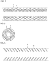
- Water described throughout the specification includes not only water in a liquid state, but also water in a gas state and "frost” means a state in which water (H 2 O) contained in the gas is finely condensed and the finely condensed particles are very loosely bonded.
- FIG. 1 is a side cross-sectional view illustrating a growth schematic view of a typical water condensed particle 4 in a gas movement pipe 2
- FIG. 2 is a longitudinal sectional view of FIG. 1
- FIG. 3 is a side cross-sectional view illustrating a growth schematic view of a frost condensed particle 6 according to an exemplary embodiment of the present invention in a gas movement pipe 2
- FIG. 4 is a longitudinal sectional view of FIG. 3 .
- the frost may be identified from FIGS. 5 and 6 which are actual photographs generated in the gas movement pipe. That is, the condensed particles are loosely bonded to each other so that even though the frost is grown to be large, the bonding is easily broken by a physical impact from the outside, for example, a flow of inflowing gas.
- the principle of removing water by phase-changing the water contained in the gas to frost is based on the Mpemba effect.
- the Mpemba effect means a phenomenon in which hot water may freeze faster than cold water under the same cooling condition.
- the water molecules are attracted to each other due to a hydrogen bond and a covalent bond between hydrogen and oxygen atom is lengthened to accumulate energy.
- the hydrogen bond is lengthened and a density of water is reduced.
- the covalent bond is shortened again to emit the accumulated energy. That is, since hot water in which a lot of energy is accumulated more quickly emits energy at the time of cooling, the hot water freezes quickly.
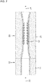
- FIG. 7 is a schematic cross-sectional view of an apparatus used to measure a density of a phase-changed frost.
- a temperature of the gas 30 which contains water is adjusted to be 60°C by a heating unit 11 while the gas 30 flows into the inflow guide pipe 10 using the apparatus illustrated in FIG. 7 .
- the gas which is adjusted within the above-mentioned temperature range is transferred to a main body 20 which is maintained at -20°C by a cooling unit 21 to change the phase of water contained in the gas to the frost 32.
- the density is calculated from a volume of the main body pipe 20 and a weight of frost at the saturation point of the phase-changed frost, that is, at the time when all spaces of the main body pipe 20 are filled with the frost 32.
- FIG. 8 is a graph illustrating a saturation point of a phase-changed frost.
- the density of the frost of the present invention measured at the time when the frost which is phase-changed by heating and then cooling the gas reaches the saturation point is represented in Table 1.
- Table 1 Density of frost (inflow temperature: 60°C, cooling temperature: -20°C) Volume (mL) Weight of frost (g) Density (g/mL) 1 0.558 0.124 0.21 2 0.572 0.128 0.22 3 0.551 0.127 0.23 4 0.568 0.131 0.24 5 0.565 0.125 0.22 6 0.564 0.128 0.23 7 0.567 0.126 0.22 Average 0.23
- Example 2 is the same as Example 1 except that an inflow temperature of a gas which contains water is adjusted to 60°C and then the gas which is adjusted to the above temperature range is transferred to the main body pipe 20 which is maintained at -30°C.
- Density of frost inflow temperature: 60°C, cooling temperature: -30°C
- Weight of frost g
- Example 3 is the same as Example 1 except that an inflow temperature of a gas which contains water is adjusted to 60°C and then the gas which is adjusted to the above temperature range is transferred to the main body pipe 20 which is maintained at -40°C.
- Density of frost inflow temperature: 60°C, cooling temperature: -40°C
- Weight of frost g
- Example 4 is the same as Example 1 except that an inflow temperature of a gas which contains water is adjusted to 60°C and then the gas which is adjusted to the above temperature range is transferred to the main body pipe 20 which is maintained at -50°C.
- Density of frost inflow temperature: 60°C, cooling temperature: -50°C
- Weight of frost g
- Example 5 is the same as Example 1 except that an inflow temperature of a gas which contains water is adjusted to 100°C and then the gas which is adjusted to the above temperature range is transferred to the main body pipe 20 which is maintained at -20°C.
- Density of frost inflow temperature: 100°C, cooling temperature: -20°C
- Weight of frost g
- Example 6 is the same as Example 1 except that an inflow temperature of a gas which contains water is adjusted to 100°C and then the gas which is adjusted to the above temperature range is transferred to the main body pipe 20 which is maintained at -30°C.
- Density of frost inflow temperature: 100°C, cooling temperature: -30°C
- Weight of frost g
- Example 7 is the same as Example 1 except that an inflow temperature of a gas which contains water is adjusted to 100°C and then the gas which is adjusted to the above temperature range is transferred to the main body pipe 20 which is maintained at -40°C.
- Density of frost inflow temperature: 100°C, cooling temperature: -40°C
- Weight of frost g
- Example 7 is the same as Example 1 except that an inflow temperature of a gas which contains water is adjusted to 100°C and then the gas which is adjusted to the above temperature range is transferred to the main body pipe 20 which is maintained at -50°C.
- Density of frost inflow temperature: 100°C, cooling temperature: -50°C
- Weight of frost g
- a density of water is approximately 1 g/mL
- a density of ice is approximately 0.92 g/mL
- a density of frost of the present invention is 0.11 to 0.24 g/mL which is approximately 1/10 to 1/5 of water or ice. That is, the frost generated by the water removing method of the present invention forms a space between crystal particles so that the density thereof is very low. Further, the space serves as a passage through which gas passes so that blockage of the channel may be minimized.
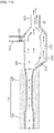
- FIG. 9 is a perspective view of an apparatus of removing water contained in a gaseous material according to an exemplary embodiment of the present invention
- FIG. 10 is a plan view of an apparatus of removing water contained in a gaseous material according to an exemplary embodiment of the present invention
- FIG. 11 is a side view of a removing apparatus illustrated in FIG. 10 , in which FIG. 11A is a side view of a gas discharging mode and FIG. 11B is a side view of a frost discharging mode.
- the apparatus of removing water contained in the gaseous material by phase-changing the water to a frost phase of the present invention includes a pollutant-contained gas inflow unit 100, a main body 200, a discharging unit 300, and a frost discharging unit 400.
- the pollutant-contained gas inflow unit 100 includes a hollow portion into which gas containing a pollutant to be measured and water flows, a heating unit 101, and a first cooling unit 102 provided at a rear end of the heating unit 101.
- the gas inflow unit 100 may also serve as a passage of air which is injected into the main body 200.
- the pollutant-contained gas inflow unit 100 is provided to phase-change the water contained in a gaseous pollutant to be measured into the frost.
- the heating unit 101 heats the inflow gas and the first cooling unit 102 provided at a rear end of the heating unit 101 cools the gas which passes through the heating unit 101.
- the heating unit 101 is equipped with a heater (not illustrated) to heat the inflow gas and the first cooling unit 102 is configured to cool the heated gas so that the inflow gas is heated or cooled to a temperature in a predetermined range.
- the first cooling unit 102 and the heating unit 101 are not specifically limited as long as they achieve the same function and the same effect.
- the first cooling unit 102 and the heating unit 101 are desirably a cooling Peltier, a heating Peltier, or a heater which exactly maintains a predetermined temperature.
- the cooling Peltier and the heating Peltier which use the Peltier effect are devices which cool or heat a specific local portion.
- DC electricity flows in a circuit after bonding both ends of two different metal lines one bonded portion absorbs heat and the other bonded portion emits heat and when the direction of current is reversed, endothermic and exothermic phenomena are reversed, which is a sort of heat pumping phenomenon and a principle of electronic refrigeration. Therefore, the cooling Peltier and heating Peltier using the above-mentioned principle have an advantage in that a temperature of a specific position is accurately maintained to a desired temperature.
- the reason why the gas inflow unit 100 is equipped with the heating unit 101 and the first cooling unit 102 is to phase-change water contained in the gaseous pollutant to frost using Mpemba effect as described above, which is one of major features of the present invention.
- the gas which flows into the heating unit 101 is desirably adjusted to be 60°C to 130°C, and more desirably, 60°C to 100°C, using the heating Peltier.
- the gas which flows into the cooling unit 102 is adjusted to be -10°C or lower, and more desirably, -20°C to -50°C, using the cooling Peltier.
- the temperature is out of a heating temperature range or a cooling temperature range
- water contained in the gas is not crystallized or the particles of the crystallized water are too large so that the water is not phase-changed to a desired frost. Therefore, it is desirable to maintain the heating temperature and the cooling temperature within the above-described range. It is obvious that when the temperature of the inflow gas falls within the heating temperature range, a separate heating step is omitted and the gas may be immediately cooled.
- the water contained in the gaseous pollutant flowing into the gas inflow unit 100 is phase-changed to a frost phase due to the Mpemba effect by the heating and/or the cooling so that the water is removed.
- particulate materials are included in the gaseous pollutant, the particulate materials are trapped in the water during the phase-changing to the frost or impinged on the phase-changed frost to be separated and removed from the gaseous flow.
- the heating unit 101 and the first cooling unit 102 are not specifically limited as long as they have a space to allow the gas to flow in and out, desirably, the heating unit 101 and the first cooling unit 102 may have a cylindrical shape having a space.
- a diameter of the first cooling unit 102 may vary according to an amount of inflow gas and a content of water contained in the gas. That is, in FIGS. 9 to 11 , it is illustrated that a diameter of one side of the first cooling unit 102 connected to the main body 200 is gradually increased. However, to the contrary, the diameter of the first cooling unit 102 at a gas outlet side may be changed to form a tapered shape which is gradually reduced.
- the first cooling unit 102 may be formed of a material having a low thermal conductivity, such as silica or glass.
- the main body 200 communicates with the pollutant-contained gas inflow unit 100, the discharging unit 300 which discharges the gaseous pollutant from which water is removed, and the frost discharging unit 400 which discharges frost 220 collected in the main body 200 to the outside.
- the main body 200 may further include a second cooling unit 240 which encloses an outer periphery of the main body 200.
- the main body 200 forms a collecting unit 230 having a concave shape at a lower portion.
- the main body 200 performs a function of transferring the gaseous pollutant from which water is removed from the pollutant-contained gas inflow unit 100 to an analyzing device and the collecting unit 230 performs a function of collecting the frost which is generated by being phase-changed in the pollutant-contained gas inflow unit 100.
- the frost which is generated in the pollutant-contained gas inflow unit 100 to be inserted is precipitated by its own weight to be collected by the collecting unit 230 and the gaseous pollutant from which water is removed moves along an upper surface of the main body 200 to flow into the analyzing device.
- the second cooling unit 240 provided at the outer periphery of the main body 200 performs a function of maintaining the temperature of the main body 200 at -1°C to -5°C so that the frost 220 collected in the main body 200 is not re-dissolved or phase-changed.
- the second cooling unit 240 may use the same cooling Peltier as the first cooling unit 102.
- the discharging unit 300 is provided at a rear end of the main body 200 as described above and performs a function of guiding the gaseous pollutant from which the water is removed to the analyzing device.
- a first shut-off valve 301 may be further included in the discharging unit 300. The first shut-off valve 301 is provided to close the discharging unit 300 when the frost 220 collected in the main body 200 is discharged to the outside so that the frost does not flow into the analyzing device.
- the discharging unit 300 is not specifically limited as long as the discharging unit has a space which allows the gas to be inserted and discharged, but desirably has a cylindrical shape having a space and a material therefor has corrosion resistance and impact resistance.
- the water contained in the inflow gas is phase-changed to the frost and collected therein.
- the collected frost 220 is excessively accumulated, there may be problems in that the frost may block the space of the main body 200 or the collected frost 220 may flow into the analyzing device through the discharging unit 300.
- a pretreatment device of the present invention further includes a frost discharging unit 400 to intermittently discharge the frost 220 collected in the collecting unit 230. Due to this configuration, the blockage of the main body 200 is avoided and the gaseous pollutant from which the water is removed may smoothly move to the discharging unit 300 along the upper surface of the main body 200.
- frost discharging unit 400 when a predetermined amount of frost is collected in the collecting unit 230, air is supplied through a air supply unit (not illustrated) which communicates with the gas inflow unit 100 through the shut-off valve and the supplied air discharges the frost collected in the collecting unit 230 to the frost discharging unit 400 (see FIG. 11B ).
- the air supplying means may supply the compressed air to the main body 200 intermittently, that is, in a pulsed manner and transfer the frost which is collected in the main body 200 by instant air supply to the frost discharging unit 400.
- air may be intermittently supplied to the outside of the main body using a vacuum means in a pulsed manner.
- the frost discharging unit 400 is provided at a rear end of the main body 200 and discharges the frost collected in the main body 200 to the outside.
- the frost discharging unit 400 may include a second shut-off valve 401 which controls the discharging of the frost.
- the frost discharging unit 400 is not specifically limited as long as the discharging unit has a space which allows the gas to be inserted and discharged, but desirably has a cylindrical shape having a space and a material therefor has corrosion resistance and impact resistance
- the first shut-off valve 301 and the second shut-off valve 401 are valves for controlling the gas or frost to be open and closed. That is, in order to remove the water from the pollutants-contained gas and supply the gas from which water is removed to the analyzing device, the first shut-off valve and the second shut-off valve are switched to a gas discharging mode as illustrated in FIG. 11A . In other words, the first shut-off valve 301 is open and the second shut-off valve 401 is closed. In contrast, in order to discharge the frost 220 collected in the main body 200 to the outside, the first shut-off valve and the second shut-off valve are switched to a frost discharging mode as illustrated in FIG. 11B . In other words, the first shut-off valve 301 is closed and the second shut-off valve 401 is open.
- FIG. 12 is a flowchart for explaining a method of removing water contained in a gaseous material of the present invention.
- the method may include a first step S110 of phase-changing water contained in a gas to a frost shape by cooling inflow gas which contains water, a second step S120 of separating the phase-changed frost and the gas from which water is removed, a third step S130 of discharging the gas from which water is removed to the outside, and a fourth step S140 of discharging the phase-changed frost to the outside.
- the first step S110 is a step of phase-changing the water contained in the gas to the frost phase as described above by cooling the gas in order to remove the water contained in the gaseous pollutant which serves as an obstacle material at the time of measurement and analysis of the gaseous pollutant.
- the cooling temperature may be adjusted to be -10°C or lower, and more desirably -20°C to -50°C.
- the method of the present invention may further include a step of heating the gas containing pollutant to a temperature in a predetermined range before the cooling step and the heating temperature may be adjusted to be 60°C to 150°C and more desirably 60°C to 100°C.
- the water contained in the gaseous pollutant is phase-changed to a frost phase by the Mpemba effect.
- the second step S120 is a step of separating and removing the frost phase-changed in the first step from the gas flow and the third step S130 is a step of guiding the gas from which the water is removed to the outside, to be more specific, to the analyzing device.
- the frost which is phase-changed in the first step S110 is precipitated by its own weight and the gas from which water is removed flows into the analyzing device to analyze the type of pollutant and/or a concentration of the pollutant.
- the particulate materials when particulate materials are included in the gaseous pollutant, the particulate materials are trapped by the water during the phase-changing to the frost or impinged on the phase-changed frost to be separated and removed from the gaseous flow.
- the fourth step S140 is a step of discharging the frost 220 which is phase-changed and collected, to the outside.
- the fourth step S140 is a step of discharging the collected frost 220 to the outside by supplying the compressed air in a pulsed manner so that the frost 220 collected in steps S120 and S130 does not flow into the analyzing device.
Landscapes
- Chemical & Material Sciences (AREA)
- Engineering & Computer Science (AREA)
- Life Sciences & Earth Sciences (AREA)
- Health & Medical Sciences (AREA)
- Physics & Mathematics (AREA)
- Analytical Chemistry (AREA)
- Chemical Kinetics & Catalysis (AREA)
- Pathology (AREA)
- General Health & Medical Sciences (AREA)
- Biomedical Technology (AREA)
- Molecular Biology (AREA)
- Immunology (AREA)
- General Physics & Mathematics (AREA)
- Biochemistry (AREA)
- Thermal Sciences (AREA)
- General Chemical & Material Sciences (AREA)
- Crystallography & Structural Chemistry (AREA)
- Oil, Petroleum & Natural Gas (AREA)
- Hydrology & Water Resources (AREA)
- Environmental & Geological Engineering (AREA)
- Water Supply & Treatment (AREA)
- Organic Chemistry (AREA)
- Combustion & Propulsion (AREA)
- Mechanical Engineering (AREA)
- General Engineering & Computer Science (AREA)
- Sampling And Sample Adjustment (AREA)
Claims (9)
- Eine Vorrichtung zum Entfernen von Wasser durch den Phasenwechsel von Wasser, das in einem gasförmigen Material enthalten ist, zu einer Frostphase, umfassend:eine Gaszuflusseinheit (100), die mit einer ersten Kühleinheit (102) an einer Seite des Hauptkörpers (200) ausgestattet ist, die den Phasenwechsel von Wasser in dem Zuflussgas, das Wasser enthält, durchführt;einen Hauptkörper (200), der den in der Gaszuflusseinheit (100) erzeugten Frost sammelt und einen Raum zum Bewegen des Gases bereitstellt, aus dem Feuchtigkeit entfernt wird;eine Entladeeinheit (300), die das Gas entlädt, aus dem die Feuchtigkeit entfernt wird und mit dem Hauptkörper (200) verbunden ist; undeine Frostentladungseinheit (400), die verbunden mit dem Hauptkörper (200) ist, um in dem Raum gesammelten Frost (220) zu entladen,dadurch gekennzeichnet, dass die Gaszuflusseinheit (100) weiterhin eine Heizeinheit (101) umfasst, die konfiguriert ist, um das Gas, das Wasser enthält, auf 60 °C bis 150 °C einzustellen,wobei die erste Kühleinheit (102) konfiguriert ist, um das durch die Heizeinheit (101) geströmte Gas auf -10 °C oder weniger einzustellen,weiterhin dadurch gekennzeichnet, dass die Kühleinheit (102) einen verjüngten Abschnitt (103) an der Seite der ersten Kühleinheit (102) umfasst, der mit dem Hauptkörper (200) verbunden ist, wobei ein Innendurchmesser in dem verjüngten Abschnitt (103) in der Richtung zum Hauptkörper (200) größer oder kleiner wird.
- Die Vorrichtung nach Anspruch 1, wobei die Gaszuflusseinheit (100) weiterhin eine gepulste Luftzufuhreinheit umfasst, die den gesammelten Frost an die Frostentladungseinheit (400) ableitet.
- Die Vorrichtung nach Anspruch 1, weiterhin umfassend:ein erstes Absperrventil (301), das in der Entladeeinheit (300) angeordnet ist und die Ableitung des Gases, aus dem das Wasser entfernt wird, steuert; undein zweites Absperrventil (401), das in der Frostentladungseinheit (400) angeordnet ist und den gesammelten Frost nach außen ableitet.
- Die Vorrichtung nach Anspruch 1, weiterhin umfassend:
eine zweite Kühleinheit (240), die den Hauptkörper (200) kühlt, so dass der in dem Hauptkörper (200) gesammelte Frost nicht aufgelöst wird, die an einer Seite des Hauptkörpers (200) bereitgestellt ist. - Die Vorrichtung nach Anspruch 1, wobei die erste Kühleinheit (102) Siliciumdioxid oder Glas enthält.
- Die Vorrichtung nach Anspruch 1, wobei der Hauptkörper (200) weiterhin eine Sammeleinheit (230) mit einer konkaven Form an einem unteren Abschnitt umfasst, um den phasengewechselten Frost zu sammeln.
- Ein Verfahren zum Entfernen von Wasser durch den Phasenwechsel von Wasser, das in einem gasförmigen Material enthalten ist, zu einer Frostphase, umfassend:einen Schritt zum Einstellen von einem Gas, das Wasser enthält, auf 60 °C bis 100 °C durch eine Heizeinheit (101);einen ersten Schritt (S110) zum Phasenwechseln von Wasser, das in dem Gas enthalten ist, zu einer Frostphase durch Abkühlen von Zulaufgas auf -20 °C bis - 50 °C, einschließlich Wasser, durch eine erste Kühleinheit (102);einen zweiten Schritt (S120) zum Trennen des phasengewechselten Frosts und des Gases, aus dem Wasser entfernt wird, in einem Hauptkörper (200);einen dritten Schritt (S130) zum Entladen des Gases, aus dem Wasser entfernt wird, nach außen durch eine Entladeeinheit (300) des Hauptkörpers (200); undein vierter Schritt (S140) zum Entladen des in der Sammeleinheit (230) des Hauptkörpers (200) gesammelten phasengewechselten Frosts (220) nach außen durch die Frostentladungseinheit (400),wobei die erste Kühleinheit (102) einen verjüngten Abschnitt (103) an der Seite der ersten Kühleinheit (102) umfasst, der mit dem Hauptkörper (200) verbunden ist, wobei ein Innendurchmesser in dem verjüngten Abschnitt (103) in der Richtung zum Hauptkörper (200) größer oder kleiner wird.
- Das Verfahren nach Anspruch 7, wobei in dem vierten Schritt (S140) der gesammelte Frost (220) zu der Frostentladungseinheit (400) durch eine gepulste Luftzufuhreinheit abgeleitet wird.
- Das Verfahren nach Anspruch 7, wobei das gasförmige Material weiterhin einen oder mehrere Schadstoffe enthält, die ausgewählt aus ultrafeinem Staub, Stickstoffoxid, Schwefeloxid, Treibhausgasen, Kohlenstoffmonoxid, Geruchsstoffen, Schwermetallen und flüchtigen organischen Verbindungen sind.
Applications Claiming Priority (3)
| Application Number | Priority Date | Filing Date | Title |
|---|---|---|---|
| KR1020150135104A KR101706995B1 (ko) | 2015-09-24 | 2015-09-24 | 기체상 물질에 함유된 물(h2o)을 서리상으로 상변화시켜 물(h2o)을 제거하는 장치 및 방법 |
| KR1020150135107A KR20170036214A (ko) | 2015-09-24 | 2015-09-24 | 기체상 물질에 함유된 물(h2o)을 서리상으로 상변화시켜 물(h2o)을 제거하는 방법 |
| PCT/KR2016/002493 WO2017052012A1 (ko) | 2015-09-24 | 2016-03-14 | 기체상 물질에 함유된 물을 서리상으로 상변화시켜 물을 제거하는 장치 및 방법 |
Publications (3)
| Publication Number | Publication Date |
|---|---|
| EP3355046A1 EP3355046A1 (de) | 2018-08-01 |
| EP3355046A4 EP3355046A4 (de) | 2019-05-22 |
| EP3355046B1 true EP3355046B1 (de) | 2021-05-12 |
Family
ID=58386157
Family Applications (1)
| Application Number | Title | Priority Date | Filing Date |
|---|---|---|---|
| EP16848738.7A Active EP3355046B1 (de) | 2015-09-24 | 2016-03-14 | Vorrichtung und verfahren zur entfernung von in einer gasphasensubstanz enthaltenem wasser durch phasenumwandlung von wasser in einer frostphase |
Country Status (4)
| Country | Link |
|---|---|
| US (1) | US10697863B2 (de) |
| EP (1) | EP3355046B1 (de) |
| CN (1) | CN108351279A (de) |
| WO (1) | WO2017052012A1 (de) |
Families Citing this family (1)
| Publication number | Priority date | Publication date | Assignee | Title |
|---|---|---|---|---|
| DE102022113558A1 (de) * | 2022-05-30 | 2023-11-30 | Hps Home Power Solutions Ag | Vorrichtung zum Trocknen eines Gasstroms |
Family Cites Families (15)
| Publication number | Priority date | Publication date | Assignee | Title |
|---|---|---|---|---|
| US5119640A (en) * | 1990-10-22 | 1992-06-09 | Conrad Richard H | Freeze-thaw air dryer |
| JP3228731B2 (ja) * | 1999-11-19 | 2001-11-12 | 株式会社荏原製作所 | ヒートポンプ及び除湿装置 |
| GB0015123D0 (en) * | 2000-06-20 | 2000-08-09 | Air Prod & Chem | Process and apparatus for removal of volatile compounds from process gases |
| NO20005576D0 (no) | 2000-09-01 | 2000-11-03 | Sinvent As | Reversibel fordampningsprosess |
| CN2485647Y (zh) * | 2001-06-20 | 2002-04-10 | 包克明 | 气体多路霜冻除水装置 |
| CN2686709Y (zh) * | 2004-03-18 | 2005-03-23 | 张宜万 | 一种脱湿装置 |
| US7305838B2 (en) * | 2005-04-05 | 2007-12-11 | Bendix Commercial Vehicle Systems Llc | Cooling compressor intake air |
| JP4786591B2 (ja) * | 2007-05-11 | 2011-10-05 | オリオン機械株式会社 | Voc冷却回収装置 |
| KR100827484B1 (ko) * | 2007-07-27 | 2008-05-06 | 김정수 | 코크 오븐가스의 타르와 수분 제거장치 및 방법 |
| KR100916521B1 (ko) * | 2007-12-20 | 2009-09-08 | 최도순 | 성에 및 김서림 제거장치 |
| GB2477293A (en) * | 2010-01-28 | 2011-08-03 | Joshua Leven Mcneil | Obtaining water from atmospheric air |
| KR101158676B1 (ko) * | 2012-04-16 | 2012-06-22 | 성도민고 | 상변화 물질을 이용한 이동형 냉각장치 |
| CN203837986U (zh) * | 2014-04-18 | 2014-09-17 | 无锡精创科技有限公司 | 一种臭氧试验设备检测气体通道除水装置 |
| CN204313550U (zh) * | 2014-11-21 | 2015-05-06 | 河南千年冷冻设备有限公司 | 一种空气自动除霜装置 |
| US10578520B2 (en) * | 2015-04-30 | 2020-03-03 | Konkuk University Industrial Cooperation Corp | Pretreatment apparatus and method for analysing air pollution detection |
-
2016
- 2016-03-14 EP EP16848738.7A patent/EP3355046B1/de active Active
- 2016-03-14 US US15/762,826 patent/US10697863B2/en active Active
- 2016-03-14 CN CN201680062412.5A patent/CN108351279A/zh active Pending
- 2016-03-14 WO PCT/KR2016/002493 patent/WO2017052012A1/ko not_active Ceased
Non-Patent Citations (1)
| Title |
|---|
| None * |
Also Published As
| Publication number | Publication date |
|---|---|
| WO2017052012A1 (ko) | 2017-03-30 |
| EP3355046A4 (de) | 2019-05-22 |
| EP3355046A1 (de) | 2018-08-01 |
| US10697863B2 (en) | 2020-06-30 |
| CN108351279A (zh) | 2018-07-31 |
| US20180231440A1 (en) | 2018-08-16 |
Similar Documents
| Publication | Publication Date | Title |
|---|---|---|
| US10161037B2 (en) | Condensation on surfaces | |
| CN102954900B (zh) | 一种在烟气中采样特种有机气体的方法 | |
| KR101654193B1 (ko) | 대기오염 측정 분석을 위한 음페바 효과를 이용한 전처리 장치 및 방법 | |
| CN102089640A (zh) | 冷凝装置 | |
| WO2003091708A3 (en) | Compact, high-efficiency condensation nucleus counter | |
| KR101976934B1 (ko) | 대기오염 측정 분석을 위한 수분 전처리 장치 및 수분 배출방법 | |
| US10578520B2 (en) | Pretreatment apparatus and method for analysing air pollution detection | |
| US10371466B2 (en) | Method of preserving heat exchange surface and method of cooling moist air | |
| KR102067887B1 (ko) | 대기 오염 분석용 고용량 수분 전처리 장치 및 그 방법 | |
| KR101654178B1 (ko) | 대기오염 측정 분석을 위한 전처리 장치 및 방법 | |
| KR102184500B1 (ko) | 연속적인 미세먼지 분석을 위한 수직형 듀얼 디졸베이터 및 그 동작방법 | |
| EP3355046B1 (de) | Vorrichtung und verfahren zur entfernung von in einer gasphasensubstanz enthaltenem wasser durch phasenumwandlung von wasser in einer frostphase | |
| KR101915380B1 (ko) | 대기오염 측정 분석용 수분 전처리 장치를 위한 성에 배출장치 | |
| BRPI0605171A (pt) | sistema de secagem de gás | |
| TWI571623B (zh) | 流體中之微粒子檢測裝置及檢測方法 | |
| Zhuang et al. | Optimization of fin surface wettability for promoting the dust removal in heat exchangers under frosting-defrosting conditions | |
| KR102143692B1 (ko) | 기체상 물질에 함유된 물(h2o)을 서리상으로 상변화시켜 물(h2o)만을 제거하는 방법 | |
| KR20130090710A (ko) | 수분제거장치 | |
| CN205580818U (zh) | 一种基于热泳原理的烟气颗粒物取样装置 | |
| KR102101074B1 (ko) | 대기 오염 분석용 수분 전처리 장치 | |
| CN110333309A (zh) | 一种基于二维色谱的颗粒物有机组分在线测量系统及方法 | |
| KR102302601B1 (ko) | 굴뚝 배기가스로부터 암모니아의 연속 측정장치 | |
| KR20170036214A (ko) | 기체상 물질에 함유된 물(h2o)을 서리상으로 상변화시켜 물(h2o)을 제거하는 방법 | |
| KR102268632B1 (ko) | 고온 굴뚝용 미세먼지 연속 측정 시스템 및 그 제어 방법 | |
| CN211784425U (zh) | 土壤热采样用冷却装置以及土壤热采样系统 |
Legal Events
| Date | Code | Title | Description |
|---|---|---|---|
| STAA | Information on the status of an ep patent application or granted ep patent |
Free format text: STATUS: THE INTERNATIONAL PUBLICATION HAS BEEN MADE |
|
| PUAI | Public reference made under article 153(3) epc to a published international application that has entered the european phase |
Free format text: ORIGINAL CODE: 0009012 |
|
| STAA | Information on the status of an ep patent application or granted ep patent |
Free format text: STATUS: REQUEST FOR EXAMINATION WAS MADE |
|
| 17P | Request for examination filed |
Effective date: 20180424 |
|
| AK | Designated contracting states |
Kind code of ref document: A1 Designated state(s): AL AT BE BG CH CY CZ DE DK EE ES FI FR GB GR HR HU IE IS IT LI LT LU LV MC MK MT NL NO PL PT RO RS SE SI SK SM TR |
|
| AX | Request for extension of the european patent |
Extension state: BA ME |
|
| DAV | Request for validation of the european patent (deleted) | ||
| DAX | Request for extension of the european patent (deleted) | ||
| A4 | Supplementary search report drawn up and despatched |
Effective date: 20190426 |
|
| RIC1 | Information provided on ipc code assigned before grant |
Ipc: B01D 7/02 20060101ALI20190418BHEP Ipc: B01D 53/26 20060101ALI20190418BHEP Ipc: G01N 33/00 20060101ALI20190418BHEP Ipc: G01N 1/22 20060101AFI20190418BHEP |
|
| RIC1 | Information provided on ipc code assigned before grant |
Ipc: B01D 7/02 20060101ALI20200819BHEP Ipc: G01N 33/00 20060101ALI20200819BHEP Ipc: B01D 53/26 20060101ALI20200819BHEP Ipc: G01N 1/22 20060101AFI20200819BHEP Ipc: B01D 5/00 20060101ALI20200819BHEP |
|
| GRAP | Despatch of communication of intention to grant a patent |
Free format text: ORIGINAL CODE: EPIDOSNIGR1 |
|
| STAA | Information on the status of an ep patent application or granted ep patent |
Free format text: STATUS: GRANT OF PATENT IS INTENDED |
|
| INTG | Intention to grant announced |
Effective date: 20201006 |
|
| GRAJ | Information related to disapproval of communication of intention to grant by the applicant or resumption of examination proceedings by the epo deleted |
Free format text: ORIGINAL CODE: EPIDOSDIGR1 |
|
| STAA | Information on the status of an ep patent application or granted ep patent |
Free format text: STATUS: REQUEST FOR EXAMINATION WAS MADE |
|
| GRAP | Despatch of communication of intention to grant a patent |
Free format text: ORIGINAL CODE: EPIDOSNIGR1 |
|
| STAA | Information on the status of an ep patent application or granted ep patent |
Free format text: STATUS: GRANT OF PATENT IS INTENDED |
|
| INTC | Intention to grant announced (deleted) | ||
| INTG | Intention to grant announced |
Effective date: 20210219 |
|
| GRAS | Grant fee paid |
Free format text: ORIGINAL CODE: EPIDOSNIGR3 |
|
| GRAA | (expected) grant |
Free format text: ORIGINAL CODE: 0009210 |
|
| STAA | Information on the status of an ep patent application or granted ep patent |
Free format text: STATUS: THE PATENT HAS BEEN GRANTED |
|
| AK | Designated contracting states |
Kind code of ref document: B1 Designated state(s): AL AT BE BG CH CY CZ DE DK EE ES FI FR GB GR HR HU IE IS IT LI LT LU LV MC MK MT NL NO PL PT RO RS SE SI SK SM TR |
|
| REG | Reference to a national code |
Ref country code: GB Ref legal event code: FG4D |
|
| REG | Reference to a national code |
Ref country code: CH Ref legal event code: EP |
|
| REG | Reference to a national code |
Ref country code: DE Ref legal event code: R096 Ref document number: 602016057865 Country of ref document: DE |
|
| REG | Reference to a national code |
Ref country code: IE Ref legal event code: FG4D |
|
| REG | Reference to a national code |
Ref country code: AT Ref legal event code: REF Ref document number: 1392499 Country of ref document: AT Kind code of ref document: T Effective date: 20210615 |
|
| REG | Reference to a national code |
Ref country code: LT Ref legal event code: MG9D |
|
| REG | Reference to a national code |
Ref country code: AT Ref legal event code: MK05 Ref document number: 1392499 Country of ref document: AT Kind code of ref document: T Effective date: 20210512 |
|
| REG | Reference to a national code |
Ref country code: NL Ref legal event code: MP Effective date: 20210512 |
|
| PG25 | Lapsed in a contracting state [announced via postgrant information from national office to epo] |
Ref country code: LT Free format text: LAPSE BECAUSE OF FAILURE TO SUBMIT A TRANSLATION OF THE DESCRIPTION OR TO PAY THE FEE WITHIN THE PRESCRIBED TIME-LIMIT Effective date: 20210512 Ref country code: FI Free format text: LAPSE BECAUSE OF FAILURE TO SUBMIT A TRANSLATION OF THE DESCRIPTION OR TO PAY THE FEE WITHIN THE PRESCRIBED TIME-LIMIT Effective date: 20210512 Ref country code: AT Free format text: LAPSE BECAUSE OF FAILURE TO SUBMIT A TRANSLATION OF THE DESCRIPTION OR TO PAY THE FEE WITHIN THE PRESCRIBED TIME-LIMIT Effective date: 20210512 Ref country code: BG Free format text: LAPSE BECAUSE OF FAILURE TO SUBMIT A TRANSLATION OF THE DESCRIPTION OR TO PAY THE FEE WITHIN THE PRESCRIBED TIME-LIMIT Effective date: 20210812 Ref country code: HR Free format text: LAPSE BECAUSE OF FAILURE TO SUBMIT A TRANSLATION OF THE DESCRIPTION OR TO PAY THE FEE WITHIN THE PRESCRIBED TIME-LIMIT Effective date: 20210512 |
|
| PG25 | Lapsed in a contracting state [announced via postgrant information from national office to epo] |
Ref country code: NO Free format text: LAPSE BECAUSE OF FAILURE TO SUBMIT A TRANSLATION OF THE DESCRIPTION OR TO PAY THE FEE WITHIN THE PRESCRIBED TIME-LIMIT Effective date: 20210812 Ref country code: PL Free format text: LAPSE BECAUSE OF FAILURE TO SUBMIT A TRANSLATION OF THE DESCRIPTION OR TO PAY THE FEE WITHIN THE PRESCRIBED TIME-LIMIT Effective date: 20210512 Ref country code: PT Free format text: LAPSE BECAUSE OF FAILURE TO SUBMIT A TRANSLATION OF THE DESCRIPTION OR TO PAY THE FEE WITHIN THE PRESCRIBED TIME-LIMIT Effective date: 20210913 Ref country code: SE Free format text: LAPSE BECAUSE OF FAILURE TO SUBMIT A TRANSLATION OF THE DESCRIPTION OR TO PAY THE FEE WITHIN THE PRESCRIBED TIME-LIMIT Effective date: 20210512 Ref country code: RS Free format text: LAPSE BECAUSE OF FAILURE TO SUBMIT A TRANSLATION OF THE DESCRIPTION OR TO PAY THE FEE WITHIN THE PRESCRIBED TIME-LIMIT Effective date: 20210512 Ref country code: IS Free format text: LAPSE BECAUSE OF FAILURE TO SUBMIT A TRANSLATION OF THE DESCRIPTION OR TO PAY THE FEE WITHIN THE PRESCRIBED TIME-LIMIT Effective date: 20210912 Ref country code: GR Free format text: LAPSE BECAUSE OF FAILURE TO SUBMIT A TRANSLATION OF THE DESCRIPTION OR TO PAY THE FEE WITHIN THE PRESCRIBED TIME-LIMIT Effective date: 20210813 Ref country code: LV Free format text: LAPSE BECAUSE OF FAILURE TO SUBMIT A TRANSLATION OF THE DESCRIPTION OR TO PAY THE FEE WITHIN THE PRESCRIBED TIME-LIMIT Effective date: 20210512 |
|
| PG25 | Lapsed in a contracting state [announced via postgrant information from national office to epo] |
Ref country code: NL Free format text: LAPSE BECAUSE OF FAILURE TO SUBMIT A TRANSLATION OF THE DESCRIPTION OR TO PAY THE FEE WITHIN THE PRESCRIBED TIME-LIMIT Effective date: 20210512 |
|
| PG25 | Lapsed in a contracting state [announced via postgrant information from national office to epo] |
Ref country code: CZ Free format text: LAPSE BECAUSE OF FAILURE TO SUBMIT A TRANSLATION OF THE DESCRIPTION OR TO PAY THE FEE WITHIN THE PRESCRIBED TIME-LIMIT Effective date: 20210512 Ref country code: EE Free format text: LAPSE BECAUSE OF FAILURE TO SUBMIT A TRANSLATION OF THE DESCRIPTION OR TO PAY THE FEE WITHIN THE PRESCRIBED TIME-LIMIT Effective date: 20210512 Ref country code: DK Free format text: LAPSE BECAUSE OF FAILURE TO SUBMIT A TRANSLATION OF THE DESCRIPTION OR TO PAY THE FEE WITHIN THE PRESCRIBED TIME-LIMIT Effective date: 20210512 Ref country code: ES Free format text: LAPSE BECAUSE OF FAILURE TO SUBMIT A TRANSLATION OF THE DESCRIPTION OR TO PAY THE FEE WITHIN THE PRESCRIBED TIME-LIMIT Effective date: 20210512 Ref country code: RO Free format text: LAPSE BECAUSE OF FAILURE TO SUBMIT A TRANSLATION OF THE DESCRIPTION OR TO PAY THE FEE WITHIN THE PRESCRIBED TIME-LIMIT Effective date: 20210512 Ref country code: SK Free format text: LAPSE BECAUSE OF FAILURE TO SUBMIT A TRANSLATION OF THE DESCRIPTION OR TO PAY THE FEE WITHIN THE PRESCRIBED TIME-LIMIT Effective date: 20210512 Ref country code: SM Free format text: LAPSE BECAUSE OF FAILURE TO SUBMIT A TRANSLATION OF THE DESCRIPTION OR TO PAY THE FEE WITHIN THE PRESCRIBED TIME-LIMIT Effective date: 20210512 |
|
| REG | Reference to a national code |
Ref country code: DE Ref legal event code: R097 Ref document number: 602016057865 Country of ref document: DE |
|
| PLBE | No opposition filed within time limit |
Free format text: ORIGINAL CODE: 0009261 |
|
| STAA | Information on the status of an ep patent application or granted ep patent |
Free format text: STATUS: NO OPPOSITION FILED WITHIN TIME LIMIT |
|
| 26N | No opposition filed |
Effective date: 20220215 |
|
| PG25 | Lapsed in a contracting state [announced via postgrant information from national office to epo] |
Ref country code: IS Free format text: LAPSE BECAUSE OF FAILURE TO SUBMIT A TRANSLATION OF THE DESCRIPTION OR TO PAY THE FEE WITHIN THE PRESCRIBED TIME-LIMIT Effective date: 20210912 Ref country code: AL Free format text: LAPSE BECAUSE OF FAILURE TO SUBMIT A TRANSLATION OF THE DESCRIPTION OR TO PAY THE FEE WITHIN THE PRESCRIBED TIME-LIMIT Effective date: 20210512 |
|
| PG25 | Lapsed in a contracting state [announced via postgrant information from national office to epo] |
Ref country code: IT Free format text: LAPSE BECAUSE OF FAILURE TO SUBMIT A TRANSLATION OF THE DESCRIPTION OR TO PAY THE FEE WITHIN THE PRESCRIBED TIME-LIMIT Effective date: 20210512 |
|
| REG | Reference to a national code |
Ref country code: DE Ref legal event code: R119 Ref document number: 602016057865 Country of ref document: DE |
|
| PG25 | Lapsed in a contracting state [announced via postgrant information from national office to epo] |
Ref country code: MC Free format text: LAPSE BECAUSE OF FAILURE TO SUBMIT A TRANSLATION OF THE DESCRIPTION OR TO PAY THE FEE WITHIN THE PRESCRIBED TIME-LIMIT Effective date: 20210512 |
|
| REG | Reference to a national code |
Ref country code: CH Ref legal event code: PL |
|
| GBPC | Gb: european patent ceased through non-payment of renewal fee |
Effective date: 20220314 |
|
| REG | Reference to a national code |
Ref country code: BE Ref legal event code: MM Effective date: 20220331 |
|
| PG25 | Lapsed in a contracting state [announced via postgrant information from national office to epo] |
Ref country code: LU Free format text: LAPSE BECAUSE OF NON-PAYMENT OF DUE FEES Effective date: 20220314 Ref country code: LI Free format text: LAPSE BECAUSE OF NON-PAYMENT OF DUE FEES Effective date: 20220331 Ref country code: IE Free format text: LAPSE BECAUSE OF NON-PAYMENT OF DUE FEES Effective date: 20220314 Ref country code: GB Free format text: LAPSE BECAUSE OF NON-PAYMENT OF DUE FEES Effective date: 20220314 Ref country code: FR Free format text: LAPSE BECAUSE OF NON-PAYMENT OF DUE FEES Effective date: 20220331 Ref country code: DE Free format text: LAPSE BECAUSE OF NON-PAYMENT OF DUE FEES Effective date: 20221001 Ref country code: CH Free format text: LAPSE BECAUSE OF NON-PAYMENT OF DUE FEES Effective date: 20220331 |
|
| PG25 | Lapsed in a contracting state [announced via postgrant information from national office to epo] |
Ref country code: BE Free format text: LAPSE BECAUSE OF NON-PAYMENT OF DUE FEES Effective date: 20220331 |
|
| PG25 | Lapsed in a contracting state [announced via postgrant information from national office to epo] |
Ref country code: HU Free format text: LAPSE BECAUSE OF FAILURE TO SUBMIT A TRANSLATION OF THE DESCRIPTION OR TO PAY THE FEE WITHIN THE PRESCRIBED TIME-LIMIT; INVALID AB INITIO Effective date: 20160314 |
|
| PG25 | Lapsed in a contracting state [announced via postgrant information from national office to epo] |
Ref country code: MK Free format text: LAPSE BECAUSE OF FAILURE TO SUBMIT A TRANSLATION OF THE DESCRIPTION OR TO PAY THE FEE WITHIN THE PRESCRIBED TIME-LIMIT Effective date: 20210512 Ref country code: CY Free format text: LAPSE BECAUSE OF FAILURE TO SUBMIT A TRANSLATION OF THE DESCRIPTION OR TO PAY THE FEE WITHIN THE PRESCRIBED TIME-LIMIT Effective date: 20210512 |
|
| PG25 | Lapsed in a contracting state [announced via postgrant information from national office to epo] |
Ref country code: MT Free format text: LAPSE BECAUSE OF FAILURE TO SUBMIT A TRANSLATION OF THE DESCRIPTION OR TO PAY THE FEE WITHIN THE PRESCRIBED TIME-LIMIT Effective date: 20210512 |
|
| PG25 | Lapsed in a contracting state [announced via postgrant information from national office to epo] |
Ref country code: TR Free format text: LAPSE BECAUSE OF FAILURE TO SUBMIT A TRANSLATION OF THE DESCRIPTION OR TO PAY THE FEE WITHIN THE PRESCRIBED TIME-LIMIT Effective date: 20210512 |